

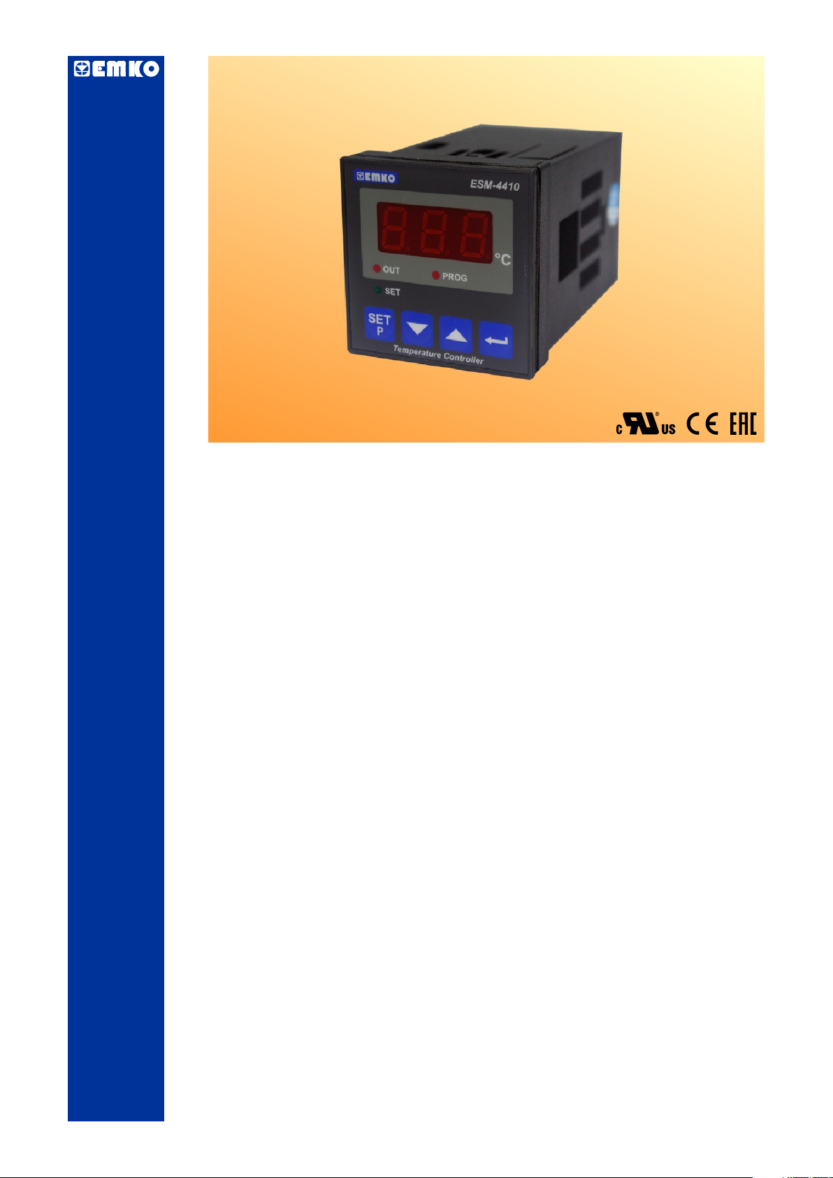
ESM-4410 48 x 48 1/16 DIN
Digital, On/Off Temperature Controller
igits display
- 3 D
- NTC Input or,
PTC Input or,
J type thermocouple or,
K type thermocouple or,
PT-100 2-wire or 3-wire temperature input
( It must be determined in order )
- ON/OFF control form
- Selectable heating and cooling function
- Operating type selection with hysteresis
- Adjustment of temperature offset value
- Minimum pulling time adjustment for control outputs
- Password protection for programming mode
ESM-4410 48 x 48 1/16 DIN Temperature Controller
Instruction Manual. ENG ESM-4410 02 V08 07/14

ABOUT INSTRUCTION MANUAL
Instruction manual of ESM-4410 Temperature Controller consists of three main sections.
Explanation of these sections are below. Also, there are other sections which include order
information and technical specifications of the device. All titles and page numbers in instruction
manual are in “CONTENTS” section. User can reach to any title with section number.
Installation:
In this section, physical dimensions of the device, panel mounting, electrical wiring are
explained.
Operation and Parameters:
In this section, user interface of the device, how to access to the parameters, description
of the parameters are explained.
Control Algorithm:
Configurable control function that is on the device is explained.
Also in these sections, there are warnings to prevent serious injury while doing the
physical and electrical mounting or using the device.
Explanation of the symbols which are used in these sections are given below.
This symbol is used for safety warnings. User must pay attention to these
warnings.
c
This symbol is used to determine the dangerous situations as a result of an electric
shock. User must pay attention to these warnings definitely.
a
This symbol is used to determine the important notes about functions and usage of
i
the device.
2

CONTENTS
1.PREFACE............................................................................................................................................
1.1 GENERAL SPECIFICATIONS
1.2 ORDERING INFORMATION
1.3 WARRANTY
1.4 MAINTENANCE
Page 5
2.INSTALLATION....................................................................................................................................
2.1 GENERAL DESCRIPTION
2.2 FRONT VIEW AND DIMENSIONS OF ESM-4410 TEMPERATURE CONTROLLER
2.3 PANEL CUT-OUT
2.4 ENVIRONMENTAL RATINGS
2.5 PANEL MOUNTING
2.6 INSTALLATION FIXING CLAMP
2.7 REMOVING FROM THE PANEL
3.ELECTRICAL WIRINGS......................................................................................................................
3.1 TERMINAL LAYOUT AND CONNECTION INSTRUCTIONS
3.2 ELECTRICAL WIRING DIAGRAM
3.3 LABELS FOR ESM-4410 TEMPERATURE CONTROLLER
3.4 SUPPLY VOLTAGE INPUT CONNECTION OF THE DEVICE
3.5 TEMPERATURE INPUT CONNECTION
3.5.1 TC (THERMOCOUPLE) CONNECTION
3.5.2 RTD CONNECTIONS
3.5.3 PTC AND NTC CONNECTIONS
3.6 GALVANIC ISOLATION TEST VALUES OF ESM-4410 TEMPERATURE CONTROLLER
3.7 OUTPUT CONNECTION
3.7.1 RELAY OUTPUT CONNECTION
3.7.2 SSR DRIVER OUTPUT CONNECTION
4.FRONT PANEL DEFINITION AND ACCESSING TO THE MENUS....................................................
4.1 FRONT PANEL DEFINITION FOR ESM-4410
4.2 OBSERVATION OF ESM-4410 TEMPERATURE CONTROLLER SOFTWARE REVISION
4.3 CHANGING AND SAVING SET VALUE
4.4 ENTERING TO PROGRAMMING MODE, CHANGING AND SAVING PARAMETERS
Page 7
Page 12
Page 17
Page 18
5.PARAMETERS....................................................................................................................................
5.1 SET PARAMETER
5.2 PROGRAM PARAMETERS
6.FAILURE MESSAGE IN ESM-4410 TEMPERATURE CONTROLLERS............................................
7.CONTROL ALGORITHM.....................................................................................................................
7.1 ON/OFF CONTROL
7.1.1 ON/OFF CONTROL IN ESM-XX10 TEMPERATURE CONTROLLERS
8.SPECIFICATIONS................................................................................................................................
9.OTHER INFORMATIONS....................................................................................................................
Page 28
Page 29
Page 30
Page 31
Page 32
3

EU DECLARATION OF CONFORMITY
Manufacturer’s Name : EMKO ELEKTRONIK A.S.
Manufacturer’s Address : DOSAB, Karanfil Sk., No:6,
16369 Bursa, TURKEY
The manufacturer hereby declares that the product:
Product Name : Temperature Controller Unit
Type Number : ESM-4410
Product Category : Electrical equipment for measurement, control and
laboratory use
Conforms to the following directives :
2006 / 95 / EC The Low Voltage Directive
2004 / 108 / EC The Electromagnetic Compatibility Directive
has been designed and manufactured to the following specifications:
EN 61000-6-4:2007 EMC Generic Emission Standard for Industrial Environments
EN 61000-6-2:2005 EMC Generic Immunity Standard for Industrial Environments
EN 61010-1:2001 Safety Requirements for electrical equipment for measurement, control
and laboratory use
When and Where Issued Authorized Signature
th
16 October 2009 Name : Serpil YAKIN
Bursa-TURKEY Position : Quality Manager
4
1.Preface
ESM series temperature controllers are designed for measuring and controlling
temperature. They can be used in many applications with On/Off control form and heating and
cooling selection. Some application fields which they are used are listed below:
Application Fields
Glass
Plastic
Petro-Chemistry
Textile
Automative
Machine Production Industries
1.1 General Specifications
Standard
ESM-4410
230 V V (±%15) , 50/60 Hz
Supply Voltage
Input
Temperature Input
Standard
Output (Relay
Output)
Optional Supply Voltage
Inputs
115 V V (±%15) , 50/60 Hz
24 V V (±%15) , 50/60 Hz
24 V W ( - %15, + %10 )
50/60 Hz
NTC
PTC
J or K Type TC
2 or 3 wire PT 100
Control Output
Alarm Output
Heating or Cooling
Function
ON/OFF Operation
5
1.2 Ordering Information
A BC D E FG HI //U V W Z/
ESM-4410 (48x48 1/16 DIN)
/0 00 2 0 0
Supply Voltage
A
24 V W ( - %15, + %10 ) 50/60 Hz
2
24 V V (±15%) 50/60 Hz
3
115 V V (±15%) 50/60 Hz
4
230 V V (±15%) 50/60 Hz
5
Customer
9
Input Type
BC
PTC (Note-1)
12
PTC (Note-1)
15
09
PT 100 , IEC751(ITS90)
PT 100 , IEC751(ITS90)
03
05
J ,Fe CuNi IEC584.1(ITS90)
10
K ,NiCr Ni IEC584.1(ITS90)
NTC (Note-1)
18
19
NTC (Note-1)
Note-1 : If input type is selected PTC or NTC (BC = 12, 15, 18, 19 ),
Temperature sensor is given with the device. For this reason,
If input type is selected as PTC, sensor type (V = 0,1 or 2) or
If input type is selected as NTC, sensor type (V = 0,3 or 4) must be
declared in ordering information.
E
Output-1
1
Relay Output(7 A@250 V at resistive load, 1NO)
2
SSR Driver Output ( )Maksimum 23 mA, 15 V Z
Scale(°C)
-50°C
-19.9°C
-19.9°C
0°C
0°C
0°C
-50°C 100°C
-19.9°C 99.9°C
150°C
99.9°C
99.9°C
400°C
800°C
999°C
All order information of ESM-4410
Temperature Controller are given on the
table at left. User may form appropriate
device configuration from information and
codes that at the table and convert it to the
ordering codes.
Firstly, supply voltage then other
specifications must be determined. Please
fill the order code blanks according to your
needs.
Please contact us, if your needs are
out of the standards.
V Þ Vac,
Z Þ Vdc,
c
Þ VacdcW
Output-2 FG
None
00
Temp.Sensor which is given with ESM-4410
V
None
0
PTC-M6L40.K1.5(PTC Air probe with 1.5 m silicon cable)
1
PTCS-M6L30.K1.5.1/8”(PTC Liquid probe with 1.5 m silicon cable)
2
NTC-M5L20.K1.5 (NTC Probe, thermoplastic moulded with
3
1.5 m cable for cooling application)
NTC-M6L50.K1.5 (NTC Probe, stainless steel housing with
4
1.5 m cable for cooling application)
Customer
9
1.3 Warranty
EMKO Elektronik warrants that the equipment delivered is free from defects in material and
workmanship. This warranty is provided for a period of two years. The warranty period starts from
the delivery date. This warranty is in force if duty and responsibilities which are determined in
warranty document and instruction manual performs by the customer completely.
1.4 Maintenance
Repairs should only be performed by trained and specialized personnel. Cut power to the device
before accessing internal parts.
Do not clean the case with hydrocarbon-based solvents (Petrol, Trichlorethylene etc.). Use of
these solvents can reduce the mechanical reliability of the device. Use a cloth dampened in ethyl
alcohol or water to clean the external plastic case.
6

2.Installation
Before beginning installation of this product, please read the instruction
manual and warnings below carefully.
c
In package ,
- One piece unit
- Two pieces mounting clamps
- One piece instruction manual
A visual inspection of this product for possible damage occured during shipment is
recommended before installation. It is your responsibility to ensure that qualified
mechanical and electrical technicians install this product.
If there is danger of serious accident resulting from a failure or defect in this unit, power
off the system and separate the electrical connection of the device from the system.
The unit is normally supplied without a power switch or a fuse. Use power switch and fuse
as required.
Be sure to use the rated power supply voltage to protect the unit against damage and to
prevent failure.
Keep the power off until all of the wiring is completed so that electric shock and trouble
with the unit can be prevented.
Never attempt to disassemble, modify or repair this unit. Tampering with the unit may
results in malfunction, electric shock or fire.
Do not use the unit in combustible or explosive gaseous atmospheres.
During the equipment is putted in hole on the metal panel while mechanical installation
some metal burrs can cause injury on hands, you must be careful.
Montage of the product on a system must be done with it’s own fixing clamps. Do not do
the montage of the device with inappropriate fixing clamps. Be sure that device will not fall
while doing the montage.
It is your responsibility if this equipment is used in a manner not specified in this
instruction manual.
7
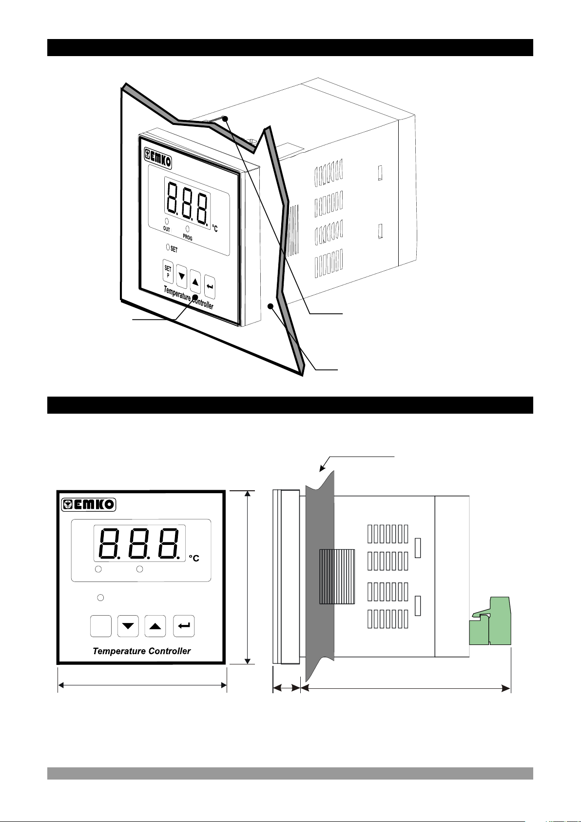
2.1 General Description
Front Panel
IP65 protection
NEMA 4X
ESM
-44
10
Mounting Clamp
Panel surface
(maximum thickness 5 mm / 0.2 inch)
2.2 Front View and Dimensions of ESM-4410 Temperature Controller
Maximum 5 mm / 0.2 inch
0
4
4
- 1
SM
E
T
U
O
T
E
S
T
E
S
P
G
O
R
P
48 mm/ 1.89 inch
48 mm/ 1.89 inch
11 ± 1 mm /0.43 inch
84 mm / 3.31 inch
8
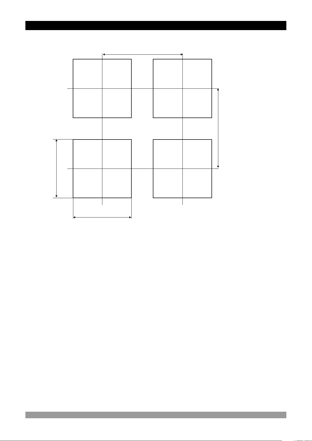
2.3 Panel Cut-Out
65 mm / 2.56 inch (min)
65 mm / 2.56 inch (min)
46 mm / 1.81 inch (min)
46 mm / 1.81 inch (min)
9
2.4 Environmental Ratings
Operating Conditions
Operating Temperature : 0 to 50 °C
Max. Operating Humidity : 90% Rh (non-condensing)
Altitude : Up to 2000 m.
Forbidden Conditions:
Corrosive atmosphere
c
Explosive atmosphere
Home applications (The unit is only for industrial applications)
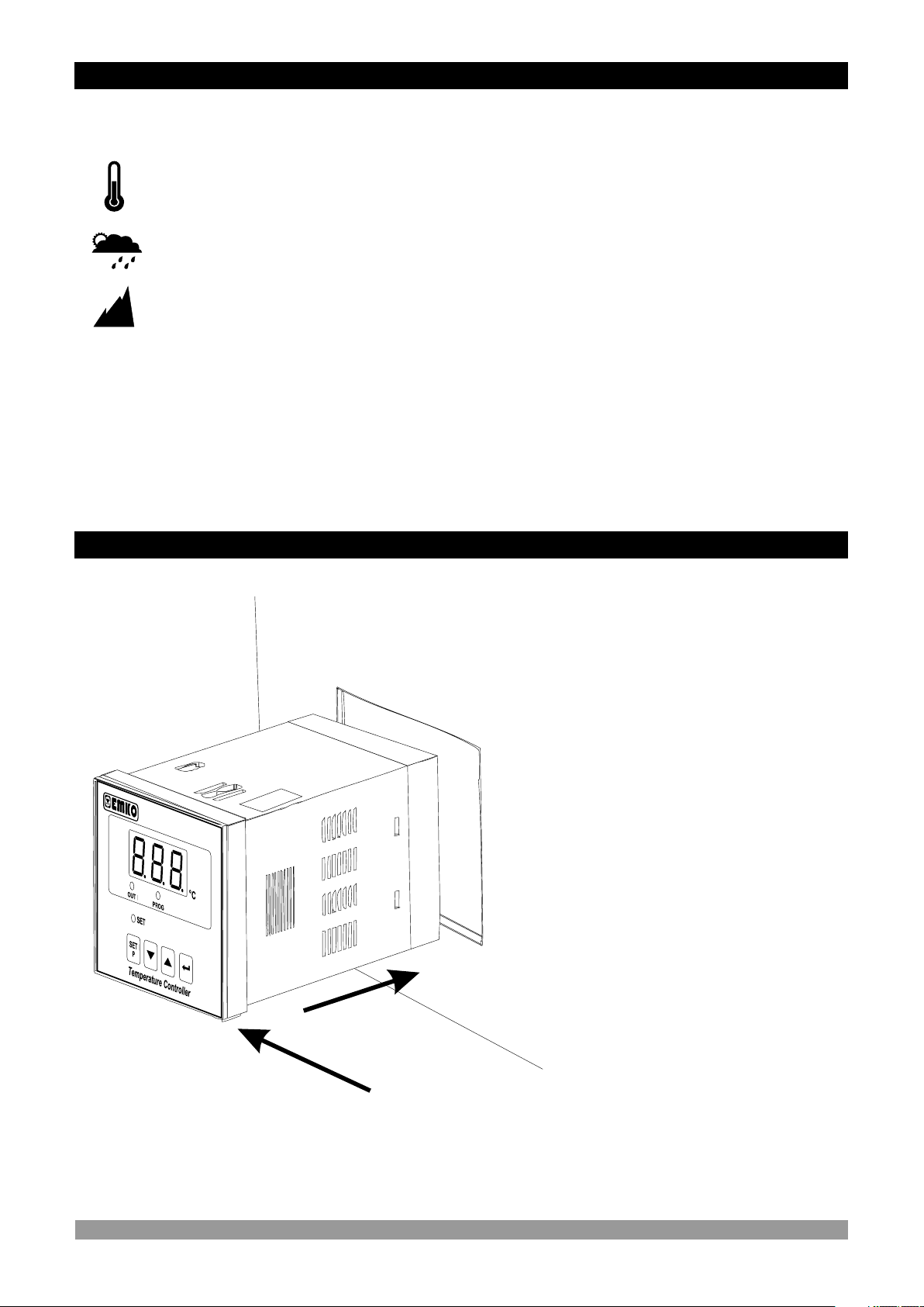
2.5 Panel Mounting
E
M
-4 0
4
1S
1
1-Before mounting the device in your
panel, make sure that the cut-out is of
the right size.
2-Check front panel gasket position
3-Insert the device through the cutout. If the mounting clamps are on the
unit, put out them before inserting the
unit to the panel.
c
3
2
During installation into a metal panel, care should be taken to avoid injury from
metal burrs which might be present. The equipment can loosen from vibration
and become dislodged if installation parts are not properly tightened. These
precautions for the safety of the person who does the panel mounting.
10
2.6 Installation Fixing Clamp
1
2
E
S -
M 441
0
Montage of the unit to a system must be done with it’s own fixing clamps. Do
not do the montage of the device with inappropriate fixing clamps. Be sure
c
2.7 Removing from the Panel
that device will not fall while doing the montage.
The unit is designed for panel
mounting.
1-Insert the unit in the panel cut-out
from the front side.
2- Insert the mounting clamps to the
holes that located top and screw up
the fixing screws until the unit
completely immobile within the panel
c
Before starting to remove the unit from panel, power off the unit and the
related system.
2
1
M 4
41ES - 0
1-Loosen the screws.
2-Pull mounting clamps from top and
bottom fixing sockets.
3-Pull the unit through the front side of
the panel
3
11
3.Electrical Wirings
You must ensure that the device is correctly configured for your application.
Incorrect configuration could result in damage to the temperature being
controlled, and/or personal injury. It is your responsibility, as the installer, to
c
c
ensure that the configuration is correct.
Device parameters has factory default values. These parameters must be set
according to the system’s needs.
Only qualified personnel and technicians should work on this equipment. This
equipment contains internal circuits with voltage dangerous to human life.
There is severe danger for human life in the case of unauthorized intervention.
Be sure to use the rated power supply voltage to protect the unit against
damage and to prevent failure.
c
Keep the power off until all of the wiring is completed so that electric shock and
trouble with the unit can be prevented.
c
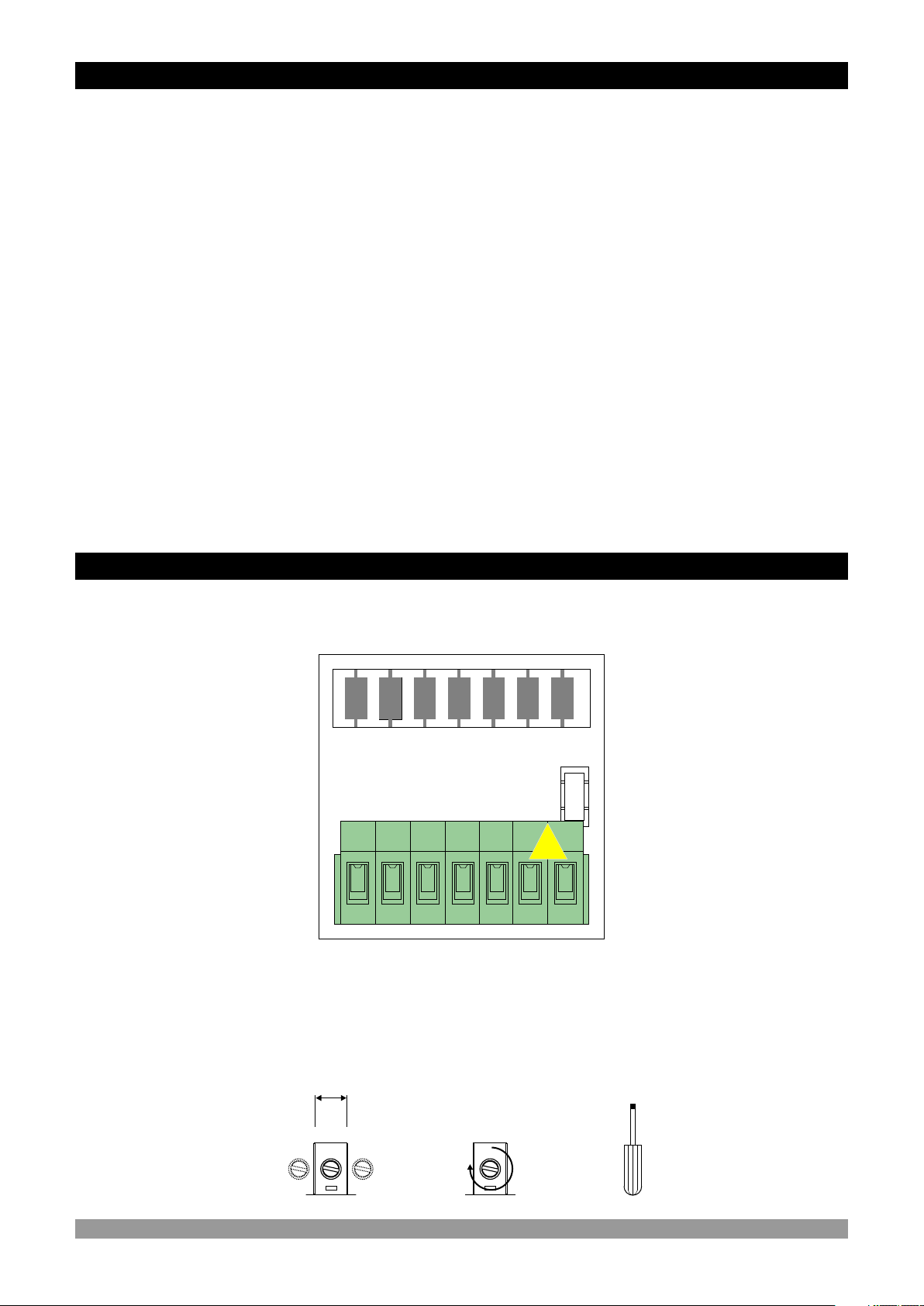
3.1 Terminal Layout and Connection Instructions
aa
Max. 2.5 mm / 0.098 inch
Wire Size:
14AWG/1 mm²
Solid /Stranded
Torque
0.5 Nm
Screw driver
0.8 x 3 mm
12
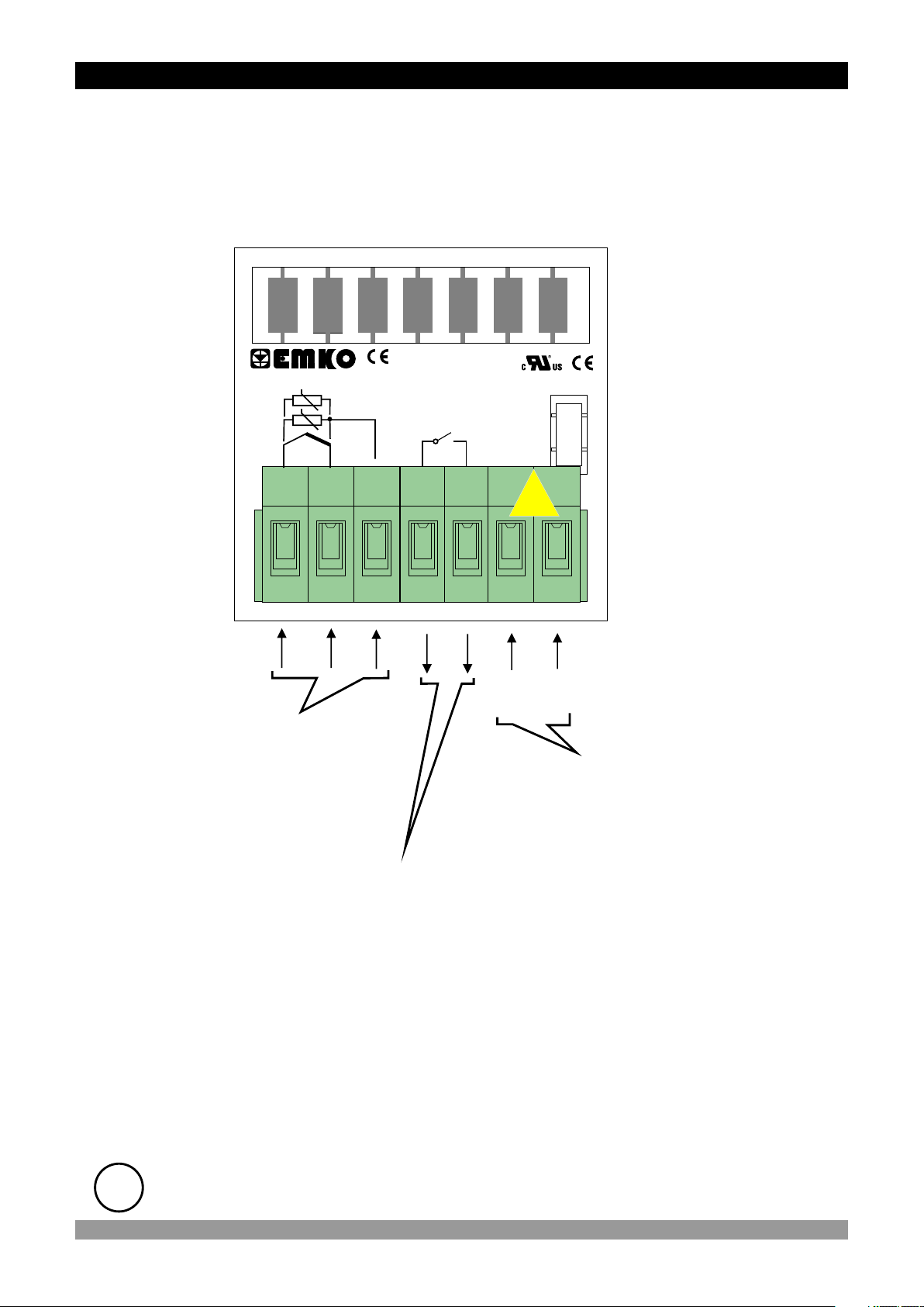
3.2 Electrical Wiring Diagram
Electrical wiring of the device must be the same as ‘Electrical Wiring Diagram’
below to prevent damage to the process being controlled and personnel
c
injury.
P/N : ESM-4410
+
TC
NTC, PTC
PT 100
ı
1 2 3 4 5 6 7
Temperature Input
(TC, PT-100, PTC or NTC)
Relay Output
Y
NOC
CAT II
c
OUTPUT
7A@250V V
aa
N
L
(+)
24 V W ( - %15, + %10 ) 50/60 Hz - 3 VA
(-)
Supply Voltage Input
230 V V (±15%) 50/60 Hz - 3 VA
115 V V (±15%) 50/60 Hz - 3 VA
24 V V (±15%) 50/60 Hz - 3 VA
(It must be determined in order)
ii
Temperature input is in CAT II class.
13

3.3 Labels for ESM-4410 Temperature Controller
Rear label appearance of the device
that have PT-100 (-19.9 C ; + 99.9 C) Scale
P/N : ESM - 4410 - 5.09.0.1/00.00/2.0.0.0
m
Pt-100
(-19.9 ; +99.9) Scale
2 31
Rear label appearance of the device
that have PTC (-19.9 ; + 99.9 ) Scale
P/N : ESM - 4410 - 5.15.0.1/00.00/2.0.0.0
m
PTC
(-19.9 ; +99.9) Scale
R W
2 31
o o
a
c
OUTPUT
7A@250VV
230 VV 15%±
50/60 Hz - 3VA
NOC
5
o o
C C
a
c
OUTPUT
7A@250VV
230 VV 15%±
50/60 Hz - 3VA
NOC
5
Y
L
64
Y
L
64
CAT II
N
7
CAT II
N
7
Rear label appearance of the device
that have PT-100 (0 C ; 400 C) Scale
P/N : ESM - 4410 - 5.03.0.1/00.00/2.0.0.0
m
Pt-100
(0 ; 400) Scale
2 31
Rear label appearance of the device
that have PTC (-50 ; 150 ) Scale
P/N : ESM - 4410 - 5.12.0.1/00.00/2.0.0.0
m
PTC
(-50 ; 150) Scale
WR
2 31
o o
a
c
OUTPUT
7A@250VV
NOC
5
o o
C C
a
c
OUTPUT
7A@250VV
NOC
5
CAT II
Y
230 VV 15%±
50/60 Hz - 3VA
L
N
7
64
CAT II
Y
230 VV 15%±
50/60 Hz - 3VA
L
N
7
64
Rear label appearance of the device
that have J Type Thermocouple
P/N : ESM - 4410 - 5.05.0.1/00.00/2.0.0.0
m
J TYPE TC
( 0 ; 800 ) Scale
o o
( 0 C ; 800 C ) Scale
a
230 VV 15%±
50/60 Hz - 3VA
NOC
5
64
Y
L
c
OUTPUT
7A@250VV
21
CAT II
N
7
Rear label appearance of the device
that have K Type Thermocouple
P/N : ESM - 4410 - 5.10.0.1/00.00/2.0.0.0
m
K TYPE TC
( 0 ; 999 ) Scale
o o
( 0 C ; 999 C ) Scale
a
230 VV 15%±
50/60 Hz - 3VA
NOC
5
64
Y
L
c
OUTPUT
7A@250VV
21
CAT II
N
7
14
3.4 Supply Voltage Input Connection of the Device
Connection of Supply Voltage Input
Y
Note-1
a
6 7
External
Fuse
(1 A T)
Power
Supply
Switch
NL
Note-2
Note-3
c
Supply Voltage
230 V V ( ± %15 ) 50/60 Hz
115 V V ( ± %15 ) 50/60 Hz
24 V V ( ± %15 ) 50/60 Hz
24 V W ( - %15, + %10 ) 50/60 Hz
Note-1 : There is an internal 33R W fusible flameproof resistor in
There is an internal 4R7 W fusible flameproof resistor in
Note-2 : “L” is (+),“N” is (-) for 24V Z Supply voltage
Note-3 : External fuse is recommended.
24VV 50/60Hz and 24VW 50/60Hz
100-240 V V 50/60Hz
c
c
c
Make sure that the power supply voltage is the same indicated on the
instrument.
Switch on the power supply only after that all the electrical connections have
been completed.
Supply voltage range must be determined in order. While installing the unit,
supply voltage range must be controlled and appropriate supply voltage must
be applied to the unit. Controlling prevents damages in unit and system and
possible accidents as a result of incorrect supply voltage.
There is no power supply switch on the device. So a power supply switch must
be added to the supply voltage input. In accordance with the safety regulations,
the power supply switch shall bring the identification of the relevant
instrument.Power supply switch shall be easily accessible by the user.
Power switch must be two poled for seperating phase and neutral. On/Off
condition of power switch is very important in electrical connection. On/Off
condition of power switch must be signed for preventing the wrong connection.
If an external fuse is used, it must be on phase connection in Vsupply input.
If an external fuse is used, it must be on (+) line connection in Zsupply input.
The instrument is protected with an internal fuse (Please refer to Note-1 for
information). In case of failure it is suggested to return the instrument to the
manufacturer for repair.
15

3.5 Temperature Input Connection
3.5.1 TC (Thermocouple) Connection
TC
1 2
3.5.2 RTD Connections
PT-100
3
Connect the wires with the polarity as shown in the figure at left.
Always use compensation wire corresponding to
the thermocouple used. If present, the shield must
ii
be connected to a proper ground.
Input resistance is greater than 10 M W.
ii
PT-100
Note 1
Note 2
1 12 23 3
3-wire PT-100 connection
(with line compensation)
(Max. Line impedance is 10 W)
Note 1 : In 3-wire system, use always cables of the same diameter (min 1mm²)
Its necessary to use cable in the same gauge and type for doing the line compensation
properly.
Note 2 : Install a jumper between terminals 2 and 3 when using a 2-wire RTD.
Note 3 : If the distance is longer than 10 meters, use 3-wire system.
Input resistance is greater than 10 M W.
ii
3.5.3 PTC and NTC Connections
PTC
RED
WHITE
2-wire PT-100 connection
(without line compensation)
NTC
1 2
ii
ii
Input resistance is greater than 10 M W.r.
While doing the PTC Probe connection, pay attention to the PTC Probe cable
colour.
1 2
16

3.6 Galvanic Isolation Test Values of ESM-4410 Temperature Controller
2000V V ( For ESM-4410.5.....,ESM-4410.4..... )
500V V ( For ESM-4410.3.....,ESM-4410.2.....)
Supply Input
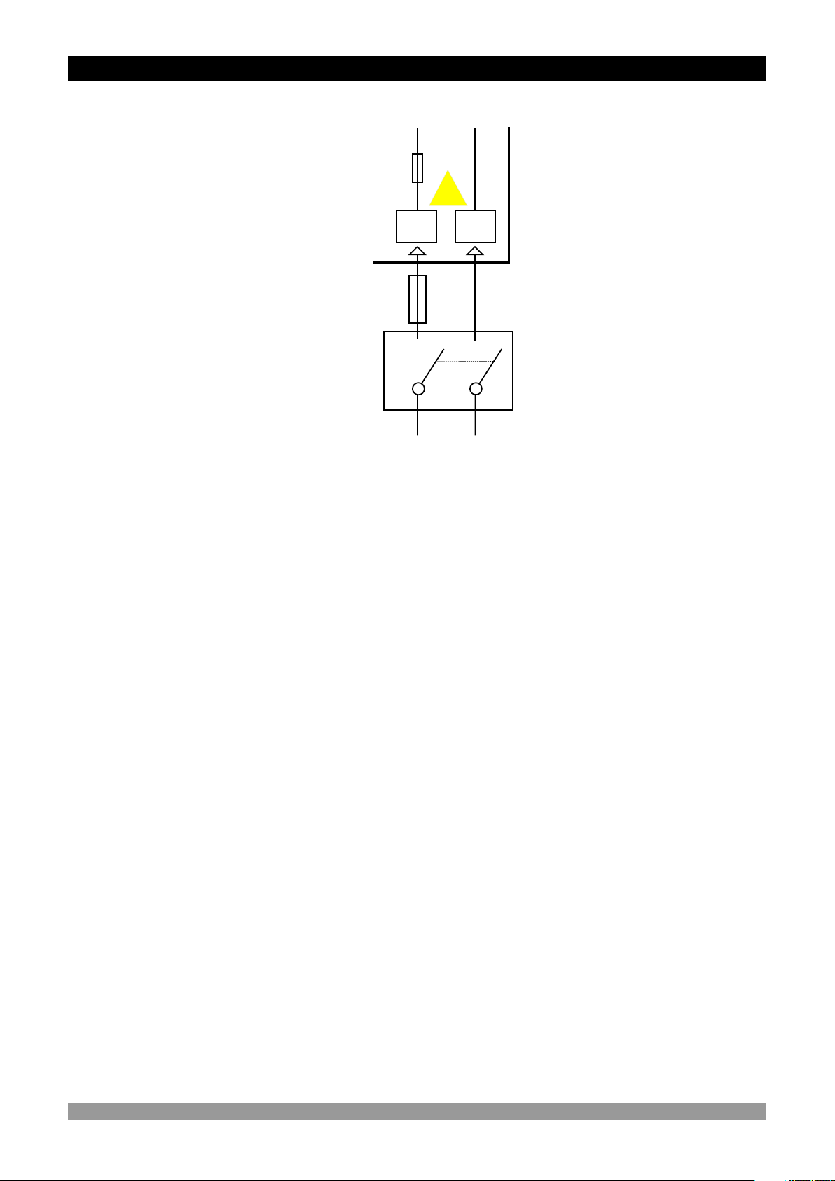
3.7 Output Connections
3.7.1 Relay Output Connection
6
7
2000V V
2000V V
Device
4
Relay Output
5
1
3
Analogue
Inputs
4
5
1
3
L N
Ground
2000V V
2
c
C
7A V T Fuse
4
Last Control Element
(Contactor)
NO
5
c
Fuse
Load
Fuses must be selected according to the application
17

3.7.2 SSR Driver Output Connection
c
Device
Last Control Element
(SSR)
L N
4
5
Max.15 V Z
Max. 23mA
Fuses must be selected according to the application.
c
Fuse
Load
18
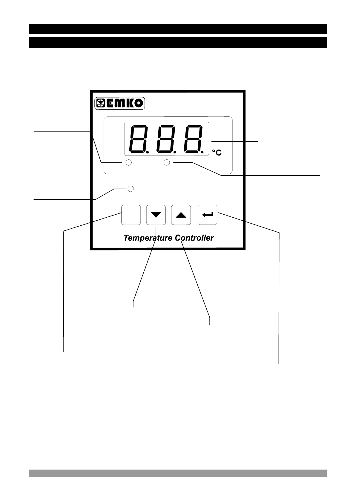
4. Front Panel Definition and Accessing to the Menus
4.1 Front Panel Definition for ESM-4410
S - 1
E
M
0
4
4
Led indication of
Output is active
Led indication of
Output Set value
OU
Displays
Temperature
Value,
Temperature Set
Value
and Parameters
T
TS
E
TS
E
P
OG
R
P
Led indication of
Programming Mode
is active
Note-1
It is used to decrease the
value
It is used to increase the
value and access to the
parameter in programming
It is used to change the Set
value, enter to and exit from
the programming mode
Note-1: In Set value or programming mode while changing the parameter, if increment or
decrement button is pressed for 5 seconds continuously, increment and decrement number
become 10, if increment or decrement button is pressed for 10 seconds continuously, increment
and decrement number become 100.
Note-1
mode
It is used to change the Set
value and confirm the
parameter in programming
mode
19

4.2 Observation of ESM-4410 Temperature Controller Software Revision
When the power is applied to the device, software revision number is momentarily shown on the
display.
0
1
4
-4
M
ES
“ r”Þ Revision
T
U
O
PR
G
O
Software
T
E
S
Revision
number
ET
S
P
1
4
4 0
-
SM
E
T
U
O
T
E
S
G
O
R
P
c
ET
S
P
Main operation screen is
shown
If there is an unexpected situation while opening the device, power off the
device and inform a qualified personnel.
20

4.3 Changing and Saving Set Value
Main Operation Screen
SET Value Screen
OUT
SET
OUT
SET
When SET button is
pressed, SET led lights on
and SET value is observed
on display.
PROG
SET
PROG
SET
SET value can be
changed with increment
and decrement buttons.
SET Value Screen
Press SET button again to
exit without saving SET
value.
Main Operation Screen
OUT
SET
OUT
SET
PROG
SET
Press Enter button for
saving SET value.
For both conditions, SET
led lights off and it turns to
main operation screen.
PROG
SET
If no operation is done in programming or Set value mode for 20 seconds, device
i
turns back to main operation screen automatically.
21

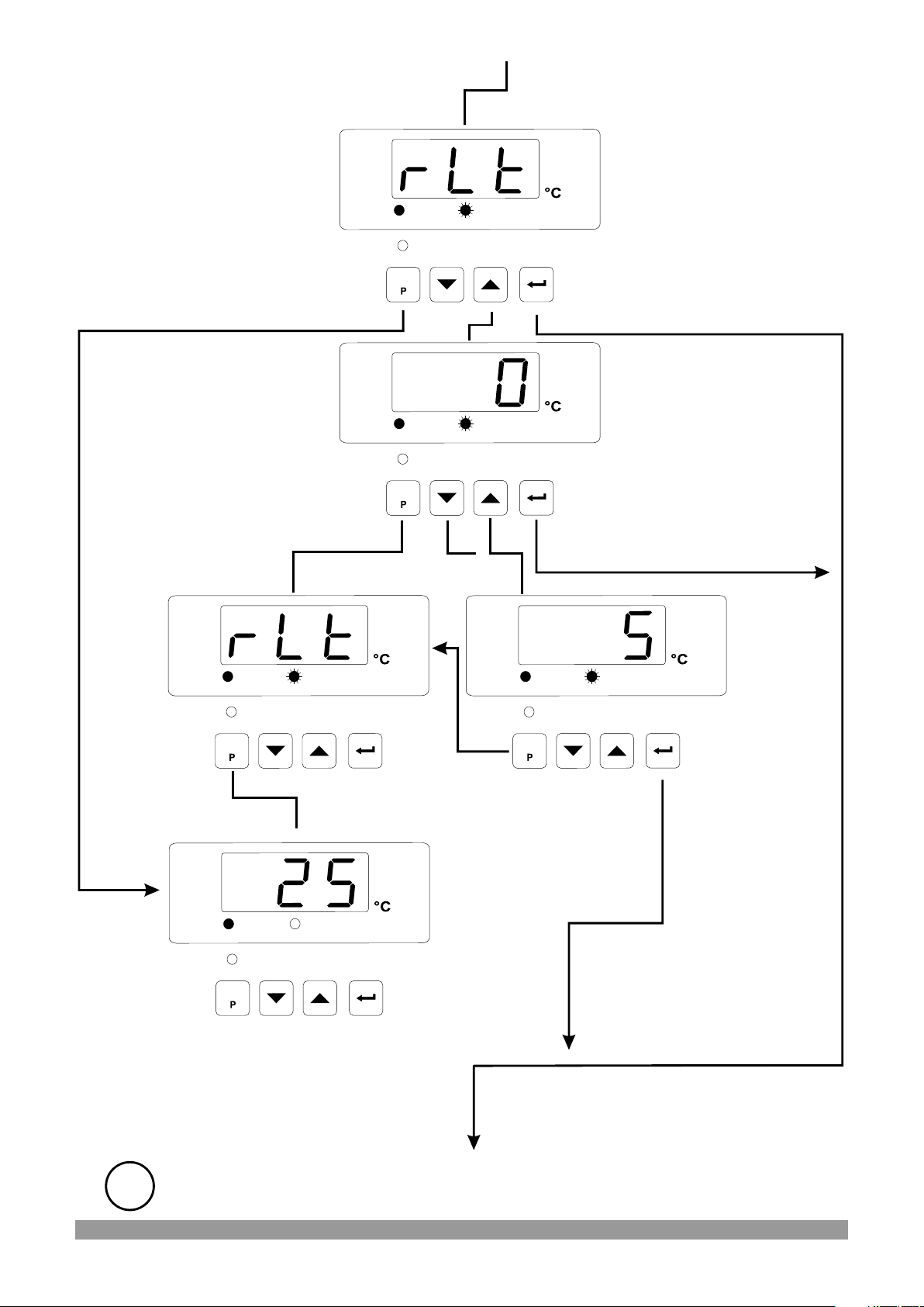
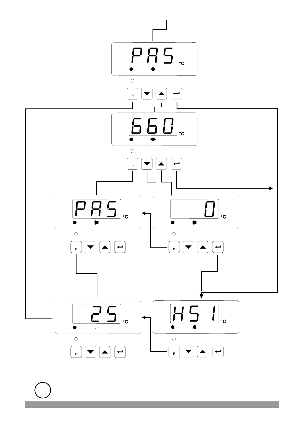
4.4 Entering to Programming Mode, Changing and Saving Parameters
Main Operation Screen
When SET button is pressed
for 10 seconds, “PROG” led
starts to blink. If programming
mode entering password is
different from 0, programming
mode entering screen
will be observed
Programming Mode
Entering Screen
In programming mode
entering screen, press SET
button to exit from
programming mode and turn
to the main operation screen.
Password Entering Screen
In password entering screen,
press SET button to return
the programming mode
entering screen
Programming Mode
Entering Screen
OUT
SET
OUT
SET
OUT
SET
SET
SET
SET
PROG
PROG
PROG
Note: If programming mode
accessing password is 0,
hysteresis screen
is observed instead of
programming screen
accessing password
Press increment button for
accessing to the password
entering screen
Parameters can be
observed by pressing Enter
button, but parameters can
not be changed.
Enter programming mode
accessing password with
increment and decrement
buttons
Parameters can be
observed by pressing Enter
button, but parameters can
not be changed.
Press SET
button to exit
programming
mode.
If no operation is done in programming or Set value mode for 20 seconds, device
i
turns to main operation screen automatically.
OUT
SET
OUT
SET
PROG
SET
PROG
SET
Main Operation Screen
OUT
SET
PROG
SET
In password entering
screen, press SET
button to return the
programming mode
entering screen
Password
Entering
Screen
Press Enter
button for
accessing to the
parameters
22

Programming Screen
In programming screen,
Press SET button to exit from
programming mode and turn
to the main operation screen.
In programming screen,
Press SET button to exit from
programming mode and turn
to the main operation screen.
Programming Screen
OUT
SET
OUT
SET
SET
SET
PROG
PROG
Hysteresis
Parameter
Parameter value can
be observed by
pressing increment
button.
If Enter button is
pressed next
parameter is shown.
Hysteresis Value
If Enter button is
pressed next
parameter is shown.
Parameter can be
changed with increment
and decrement buttons.
Press SET
button to exit
from
programming
mode.
OUT
SET
OUT
SET
PROG
SET
PROG
SET
Main Operation Screen
OUT
SET
PROG
SET
Press SET button
to turn to the
programming
screen without
saving the
parameter.
Hysteresis
Value
Press Enter
button for saving
parameter
value.
If no operation is done in programming or Set value mode for 20 seconds, device
i
turns to main operation screen automatically.
23

Programming Screen
In programming screen,
Press SET button to exit from
programming mode and turn
to the main operation screen.
In programming screen,
Press SET button to exit from
programming mode and turn
to the main operation screen.
Programming Screen
OUT
SET
OUT
SET
SET
SET
PROG
PROG
Operation Type
Selection for Output
Parameter value can
be observed by
pressing increment
button.
If Enter button is
pressed next
parameter is shown.
Value of Operation
Type Selection for
Output
Heating is selected
If Enter button is
pressed next
parameter is shown.
Parameter can be
changed with increment
and decrement buttons.
Press SET
button to exit
from
programming
mode.
OUT
SET
OUT
SET
PROG
SET
PROG
SET
Main Operation Screen
OUT
SET
PROG
SET
Press SET button
to turn to the
programming
screen without
saving the
parameter.
Value of
Operation
Type
Selection
for Output
It is changed as
cooling
Press Enter
button for saving
parameter
value.
If no operation is done in programming or Set value mode for 20 seconds, device
i
turns to main operation screen automatically.
24

Programming Screen
In programming screen,
Press SET button to exit from
programming mode and turn
to the main operation screen.
Press SET button to turn
to the programming
screen without saving
the parameter.
Programming Screen
OUT
SET
OUT
SET
SET
SET
PROG
PROG
Process Offset
Parameter
Parameter value can be
observed by pressing
increment button.
If Enter button is
pressed, next
parameter is shown.
Process Offset Value
If Enter button is
pressed, next parameter
is shown.
Parameter can be
changed with increment
and decrement buttons.
Press SET
button to exit
from
programming
mode.
OUT
SET
OUT
SET
PROG
SET
PROG
SET
Main Operation Screen
OUT
SET
PROG
SET
Press SET button
to turn to the
programming
screen without
saving the
parameter.
Process
Offset
Value
Press Enter
button for saving
parameter
value.
If no operation is done in programming or Set value mode for 20 seconds, device
i
turns to main operation screen automatically.
25
Programming Screen
In programming screen,
Press SET button to exit from
programming mode and turn
to the main operation screen.
Press SET button to
turn to the
programming screen
without saving the
parameter.
Programming Screen
OUT
SET
OUT
SET
SET
SET
PROG
PROG
Minimum Pulling Time
for Output Parameter
Parameter value can be
observed by pressing
increment button.
If Enter button is
pressed, next
parameter is shown.
Value of Minimum
Pulling Time for Output
If Enter button is
pressed, next parameter
is shown.
Parameter can be
changed with increment
and decrement buttons.
Press SET
button to exit
from
programming
mode.
OUT
SET
OUT
SET
PROG
SET
PROG
SET
Main Operation Screen
OUT
SET
PROG
SET
Press SET button
to turn to the
programming
screen without
saving the
parameter.
Value of
Minimum
Pulling
Time for
Output
Press Enter
button for saving
parameter
value.
If no operation is done in programming or Set value mode for 20 seconds, device
i
turns to main operation screen automatically.
26
Programming Screen
In programming screen,
Press SET button to exit from
programming mode and turn
to the main operation screen.
OUT
SET
SET
PROG
Programming Mode
Accessing Password
Parameter value can be
observed by pressing
increment button.
If Enter button is
pressed, next
parameter is shown.
Programming Mode
Accessing Password
Value
Press SET button to
turn to the
programming screen
without saving the
parameter.
Programming Screen
OUT
SET
SET
Press SET
button to exit
from
programming
mode.
PROG
OUT
SET
SET
PROG
OUT
SET
PROG
SET
Press SET button to turn to
the programming screen
without saving the
parameter.
Programming Screen
If Enter button is
pressed, next parameter
is shown.
Parameter can be
changed with increment
and decrement buttons.
Programming
Mode
Accessing
Password
Value
Press Enter
button for
saving
parameter
value.
Hysteresis
Parameter
It turns to
beginning of
OUT
SET
PROG
SET
Main Operation Screen
OUT
SET
Press SET button to
exit from programming
section
SET
PROG
the
programming
mode
Continue to press SET2/Enter
button for accessing to the
parameters.
If no operation is done in programming or Set value mode for 20 seconds, device
i
turns to main operation screen automatically.
27

5. Parameters
Parameters are divided into two groups as SET and PROGRAM parameters.
5.1 Set Parameter
SET value for Output. Control of output relay is done according to this value.
SET1
5.2 Program Parameters
This value can be adjusted according to input type, minimum and maximum
of scale.
Hysteresis Parameter for Output ( Default = 3 )
1 to 100 °C for TC Type Devices,
1 to 100 °C for PT-100 (0°C , 400°C),
0.1 to 10.0 °C for PT-100 (-19.9°C, 99.9°C),
1 to 100 °C for PTC (-50°C, 150°C),
0.1 to 10.0 °C for PTC (-19.9°C, 99.9°C) and NTC (-19.9°C, 99.9°C)
1 to 20 °C for NTC (-50°C, 100°C)
Operation Type Selection parameter for output
Operation type of output relay can be adjusted as
“HEATING”. Normally energised.
Operation type of output relay can be adjusted
“COOLING”. Normally de-energised.
Process Offset Parameter (Default = 0).
This parameter is offset for the process value. This defined value is added to
the process value.
-10 to 10 °C for TC Type Devices,
-10 to 10 °C for PT-100 (0°C , 400°C),
-10.0 to 10.0 °C for PT-100 (-19.9°C, 99.9°C),
-10 to 10 °C for PTC (-50°C, 150°C),
-10.0 to 10.0 °C for PTC (-19.9°C, 99.9°C) and NTC (-19.9°C, 99.9°C)
-10 to 10 °C for NTC (-50°C, 100°C)
Minimum Pulling Time Parameter for Output (Minimum Off Time)
(Default = 0)
When Output is inactive this time must be expired for Output to become active
again. It can be adjusted from 0 to 100 seconds
Programming Mode Accessing Password ( Default =0 )
It is used for accessing to the programming mode. It can be adjusted from 0 to
999. If it is selected 0, password is not entered for accessing to the
parameters.
If no operation is done in programming or Set value mode for 20 seconds, device
i
turns to main operation screen automatically.
28
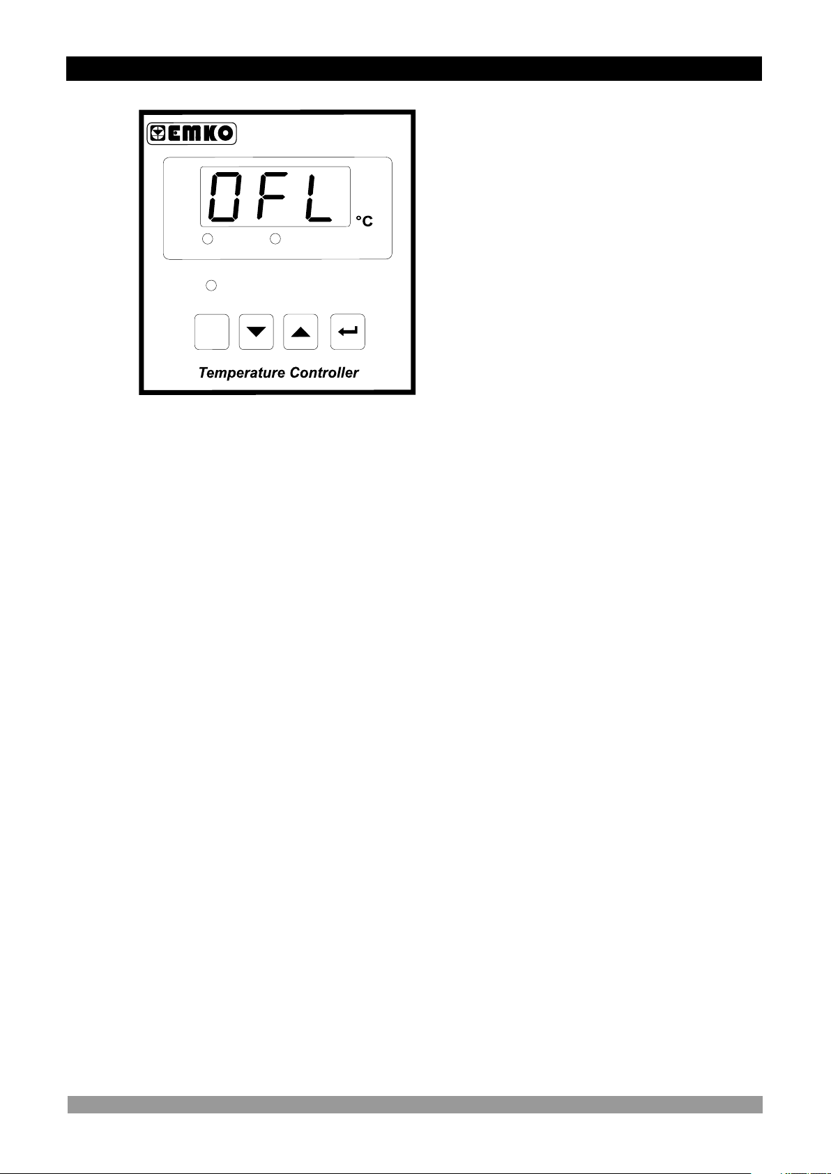
6. Failure Message in ESM-4410 Temperature Controllers
0
1
44
-
M
S
E
Sensor failure in analogue inputs. It means
sensor connection is wrong or there is no
sensor.
T
U
O
T
E
S
T
E
S
P
G
O
R
P
29
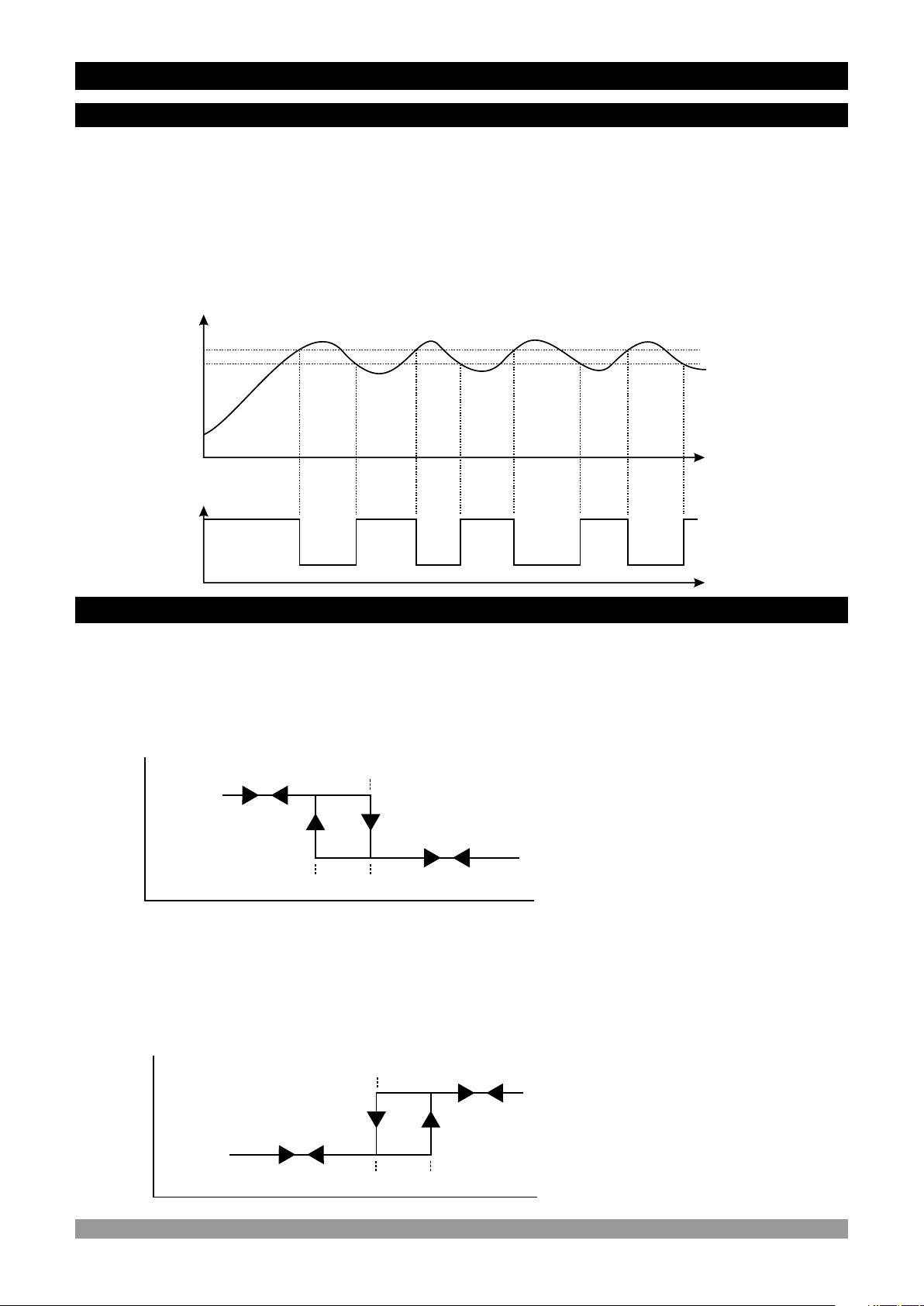
7. Control Algorithm
7.1 ON/OFF Control
In ON/OFF control algorithm, temperature value is tried to keep equal to set value by
opening or closing the last control element. ON/OFF controlled system, temperature value
oscillates continuously. Temperature value’s oscillation period or amplitude around set value
changes according to controlled system. For reducing oscillation period of temperature value,
a threshold zone is formed below or around set value and this zone is named hysteresis. Action
of control output is described with figures below.
Temperature
Temperature
Set Value
Hysteresis
Time
Temperature
Control Output
ON
OFF
Time
7.1.1 ON/OFF Control in ESM-XX10 Temperature Controller
ON/OFF control algorithm in temperature control output which has heating function
Temperature
Control
Output
Temperature
Set
ON
OFF
HYS
Temperature
ON/OFF control algorithm in temperature control output which has cooling function
Temperature
Control
Output
Temperature
Set
ON
OFF
HYS
Temperature
30

8. Specifications
Device Type : Temperature Controller
Housing&Mounting : 48 mm x 48 mm x 95 mm 1/16 DIN 43700 plastic housing
for panel mounting. Panel cut-out is 46 x 46 mm
Type-1 Enclosure Mounting
Protection Class : NEMA 4X (IP65 at front, IP20 at rear)
Weight : Approximately 0.16 Kg.
Environmental Ratings : Standard, indoor at an altitude of less then 2000 meters
with non-condensing humidity
Storage/Operating Temperature : -40 C to +85 C / 0 C to +50 C
o o o o
Storage/Operating Humidity : 90 % max. (Non-condensing)
Installation : Fixed installation
Over Voltage Category : II
Pollution Degree : II, office or workplace, none conductive pollution
Operating Conditions : Continuous
Supply Voltage and Power : 230 V V (±15%) 50/60 Hz. 3 VA
115 V V (±15%) 50/60 Hz. 3 VA
24 V V (±15%) 50/60 Hz. 3 VA
24 V (-%15, +%10) 50/60 Hz. 3 VA
W
Temperature Inputs : NTC, PTC, TC, RTD
NTC Input Types : N
TC (10 kW @.25 °C )
PTC Input Type : PTC (1000 W @.25 °C )
Thermocouple Input Types : J,
Thermoresistance Input Type :
K (IEC584.1)(ITS90)
PT 100 (IEC751(ITS90)
Accuracy : ± 1% of FS for Thermocouple, Thermoresistance
Cold Junction Compensation : Automatically ± 0.1°C/1°C
Line Compensation : Maximum 10 W
Sensor Break Protection : Upscale
Sampling Cycle : 3 samples per second
Control Forms : ON / OFF
Relay Outputs : 7 A@250 V V at resistive load
(Electrical Life : 100.000 Operation (Full Load))
Opsiyonel SSR Driver : Maximum 23 mA, Maximum 15 V Z
Output
Display : 10 mm Red 3 digits LED display
Led Indicators : SET (Green), OUT (Red), PROG (Red) 3 mm
Approvals : UL Recognized Component (File No : E 254103),
,
CECE
31

9. Other Informations
Manufacturer Information:
Emko Elektronik Sanayi ve Ticaret A.Ş.
Demirtaş Organize Sanayi Bölgesi Karanfil Sk. No:6 16369
BURSA/TURKEY
Phone : +90 224 261 1900
Fax : +90 224 261 1912
Repair and Maintenance Service Information:
Emko Elektronik Sanayi ve Ticaret A.Ş.
Demirtaş Organize Sanayi Bölgesi Karanfil Sk. No:6 16369
BURSA/TURKEY
Phone : +90 224 261 1900
Fax : +90 224 261 1912
Your Technology Partner
Thank you very much for your preference to use Emko Elektronik
Products.
www.emkoelektronik.com.tr
32
 Loading...