


XFAL-020Z-TFC
Emerson XFAL-020Z-TFC, XFAL-030Z-TFC, XFAL-035Z-CFV, XFAL-040Z-CFV, XFAL-040Z-TFC Installation And Reference Manual
...
Copeland Scroll™ Outdoor Refrigeration Unit
Installation and reference manual
Models:
XFAL, XFAM, XFAP
1.5 to 6 HP

AE5-1412 R1
AE5-1412 R1
August 2016
Copeland Scroll™ Outdoor Refrigeration Unit
X-Line User Manual
TABLE OF CONTENTS
Section Page Section Page
1. Introduction .......................................................4
2. Nomenclature ....................................................4
3. Electrical/Physical Data ...................................5
4. Installation/Piping Instructions .......................5
5. Quick Setup Guide ............................................6
6. User Interface ....................................................7
6.1. Button Descriptions and Key Combinations....... 8
6.2. Changing a Parameter Value ............................. 8
6.3. Entering the Advanced Options Menu ............... 8
6.4. Moving Parameters Between the Programming
Menu and the Advanced Options Menu ............. 8
6.5. Locking the Keypad ........................................... 8
6.6. Unlocking the Keypad ........................................ 8
6.7. Changing Clock Setting .................................... 9
6.8. Refrigerant Selection ......................................... 9
6.9. Fast Access Menu.............................................. 9
6.9.1 List of Fast Access Parameters ................9
6.10. Alarm Menu ...................................................... 10
6.11. How to Program a Hot Key From the Controller
(UPLOAD) ........................................................ 10
6.12. How to Program a Controller Using a Hot Key
(download) ....................................................... 10
6.13. Manual Stepper Control Mode for Vapor Injection
(Low Temp) or Liquid Injection (Medium Temp) 10
6.14. Controller Startup ............................................. 11
6.15. Bump Start Control Operation.......................... 11
6.16. Compressor Stop Program .............................. 11
6.17. Crankcase Heater ............................................ 12
6.18. Suction Pressure Control ................................. 12
6.19. Fan Control ...................................................... 12
6.19.1. Fan Overrides and Error Handling ....... 12
6.20. Defrost Controls ............................................... 13
6.20.1. Holiday Defrosts................................... 13
6.20.2. Defrost Functionality ............................ 13
6.20.3. Liquid Line Solenoid Control ................ 13
6.21. Enhanced Vapor Injection (EVI) for Low
Temperature Units............................................ 13
6.21.1. Low Temp EVI Discharge Line
Temperature Protection Mode.............. 13
6.21.1.1. Low Temp EVI Discharge Line
Temperature Protection Error
Handling ................................ 14
6.21.2. EVI SYSTEM CHECKS
(XFAL Units Only) ............................................ 14
6.21.3 Constant Liquid Temperature Mode for
Low Ambient EVI Injection .................... 14
6.22. Medium Temperature DLT Protection .............. 14
6.22.1. Medium Temperature DLT Protection
Error Handling .................................................. 14
6.23. Over-Current Protection ................................... 14
6.24. Incorrect Phase Sequence Protection (3 Phase
Only) ................................................................ 15
6.25. Loss of Phase Protection - Current (3 Phase
Only) ................................................................ 15
6.26. Open Run Circuit (Single Phase Only) ............ 15
6.27. Open Start Circuit ............................................ 15
6.28. Over/Under Voltage Protection ........................ 15
6.29. Phase Imbalance (3 Phase Only) .................... 15
6.30. Compressor Internal Thermal Protection ......... 15
6.31. Fixed High Pressure Control ............................ 16
6.32. Alarm Contact .................................................. 16
6.33. Anti-Floodback Warning ................................... 16
6.34. High Condensing Temperature Warning .......... 16
7. Condensing Unit Operational Control ..........16
8. Physical and Installation Requirements ......17
9. Wiring Diagrams .............................................20
10. Refrigerant Liquid Temperature Valve
Capacity Multiplier Correction Factors .........28
11. Alarm Codes ...................................................29
12. Sensor Values .................................................31
13. Parameters ...................................................... 32
© 2016 Emerson Climate Technologies, Inc.
552-7018-00
1
AE5-1412 R1
Safety Instructions
Copeland Scroll™ compressors are manufactured according to the latest U.S. and European Safety
Standards. Particular emphasis has been placed on the user's safety. Safey icons are explained below
and safety instructions applicable to the products in this bulletin are grouped on Page 3. These
instructions should be retained throughout the lifetime of the compessor. You are strongly advised
to follow these safety instructions.
Safety Instructions
Copeland Scroll™ compressors are manufactured according to the latest U.S. and European Safety Standards.
Particular emphasis has been placed on the user's safety. Safey icons are explained below and safety instructions
applicable to the products in this bulletin are grouped on Page 3. These instructions should be retained throughout
the lifetime of the compressor. You are strongly advised to follow these safety instructions.
Safety Icon Explanation
DANGER
WARNING
CAUTION
NOTICE
CAUTION
DANGER indicates a hazardous situation which, if not avoided, will result
in death or serious injury.
WARNING indicates a hazardous situation which, if not avoided, could
result in death or serious injury.
CAUTION, used with the safety alert symbol, indicates a hazardous
situation which, if not avoided, could result in minor or moderate injury.
NOTICE is used to address practices not related to personal injury.
CAUTION, without the safety alert symbol, is used to address practices
not related to personal injury.
© 2016 Emerson Climate Technologies, Inc.
2
AE5-1412 R1
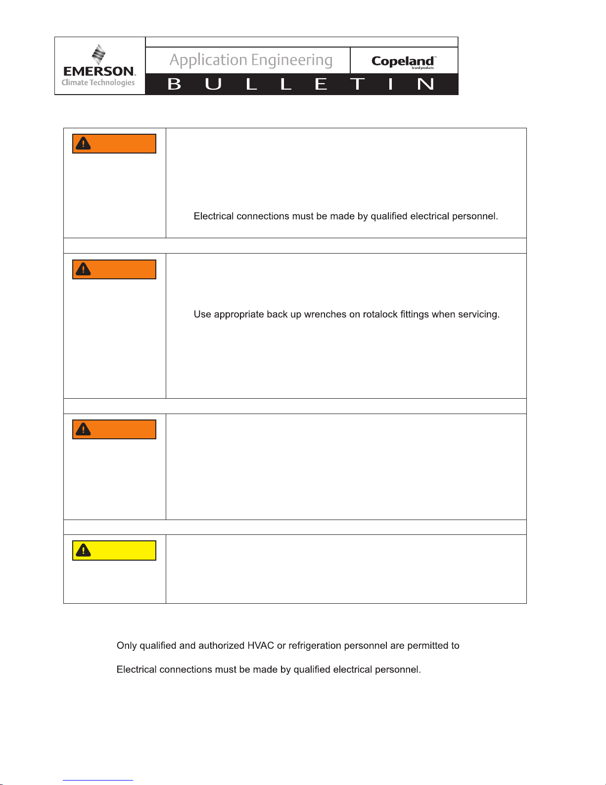
Instructions Pertaining to Risk of Electrical Shock, Fire, or Injury to Persons
WARNING
WARNING
WARNING
ELECTRICAL SHOCK HAZARD
• Disconnect and lock out power before servicing.
• Discharge all capacitors before servicing.
• Use compressor with grounded system only.
• Molded electrical plug must be used when required.
• Refer to original equipment wiring diagrams.
•
• Failure to follow these warnings could result in serious personal injury.
PRESSURIZED SYSTEM HAZARD
• System contains refrigerant and oil under pressure.
• Remove refrigerant from both the high and low compressor side before
removing compressor.
•
• Never install a system and leave it unattended when it has no charge,
a holding charge, or with the service valves closed without electrically
locking out the system.
• Use only approved refrigerants and refrigeration oils.
• Personal safety equipment must be used.
• Failure to follow these warnings could result in serious personal injury.
BURN HAZARD
• Do not touch the compressor until it has cooled down.
• Ensure that materials and wiring do not touch high temperature areas of
the compressor.
• Use caution when brazing system components.
• Personal safety equipment must be used.
• Failure to follow these warnings could result in serious personal injury or
property damage.
CAUTION
Safety Statements
• Refrigerant compressors must be employed only for their intended use.
•
install, commission and maintain this equipment.
•
• All valid standards and codes for installing, servicing, and maintaining electrical and
refrigeration equipment must be observed.
© 2016 Emerson Climate Technologies, Inc.
COMPRESSOR HANDLING
• Use the appropriate lifting devices to move compressors.
• Personal safety equipment must be used.
• Failure to follow these warnings could result in personal injury or
property damage.
3

AE5-1412 R1
1. Introduction
Copeland Scroll™ Outdoor Refrigeration Units provide
the many benets of scroll compressor technology,
coupled with advanced diagnostic controls, to ensure
reliable performance and operation in foodservice
applications.
Electronics are used extensively in its protection and
diagnostic features. These features are controlled by
an electronic integrated control module. The Dixell
XCM25D control module with CoreSense™ technology
provides control functions related to temperature and
pressure control, defrost, and compressor protection.
Units are available in 1.5 to 6 HP for coolers and 2 to
6 HP for freezers. All units are 208/230 volts and are
available in single or three phase. All -081 bill of material
units come factory equipped with a heated and insulated
receiver, service valves, pressure controls, defrost
control, lter drier, moisture indicator, crankcase heater,
variable speed condenser fan, CoreSense Protection,
CoreSense Diagnostics, and two-way communications
standard.
Low temperature XFAL units (-40°F to 0°F saturated
suction) also feature an accumulator and oil separator.
Discharge line temperature control is provided by
enhanced vapor injection (EVI).
™
Discharge line temperature control is accomplished by
suction line liquid injection.
Extended medium temp XFAP units (-25F to +45F
saturated suction) feature an accumulator. Discharge
line temperature control is accomplished by suction line
liquid injection.
The Dixell XCM25D Electronic Control Module with
CoreSense technology (control module) on Copeland™
condensing units provides many benefits to the
contractor and end-user. It is designed specically for
demanding refrigeration applications to ensure simple
installation and precision operation. While the control
module replaces existing adjustable low pressure
controls, fan cycle switches and other relays, it also
has additional features. These features include bump
start, data storage, communication, and short cycling
protection.
The control module is preprogrammed with the proper
settings, resulting in little to no setup time. The unit
comes with instructions showing how to adjust the low
pressure cut-in and cut out. See the label on the inside
of the enclosure for more information.
Condensing unit operating range: -40°F to +120°F
Medium temperature XFAM units (0°F to +45°F
saturated suction) include all the standard features.
2. Nomenclature
Nomenclature
X F A M – 0 2 0 Z – T F C – 0 8 1
Family = X-Line
F = Multi-refrigerant
Z = Scroll
60Hz
L = Low Temp
A = Air-Cooled
M = Medium Temp
P = Multiple Applications
1.5 to 6.0 = H.P.
CFV = 208/230V-1ph-
Base Model Electrical Bill of Material
TFC = 208/230V-3ph-
60Hz
81 = Standard
0 = UL Listed Product
© 2016 Emerson Climate Technologies, Inc.
4
AE5-1412 R1
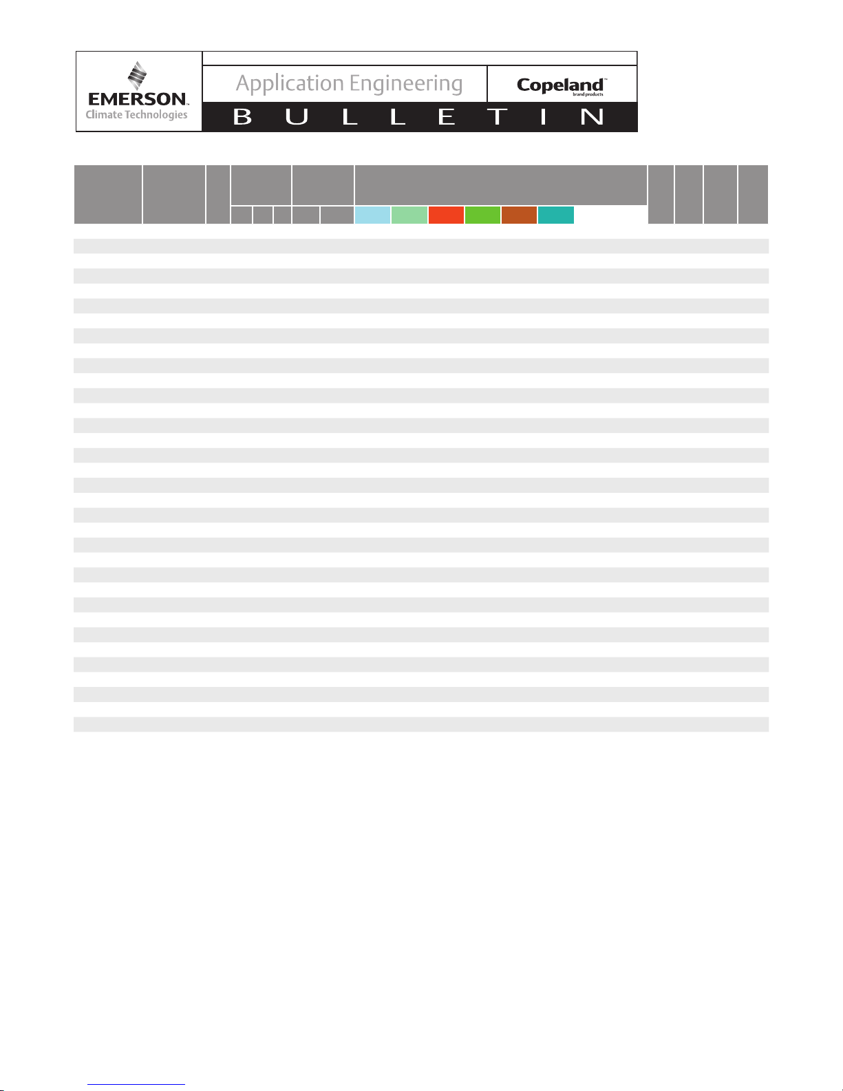
3. Electrical/Physical Data
Overall
Dimensions
Model Compressor
XFAL-020Z-CFV ZXI06KCE-PFV 1 16.7 40.5 33.1 1/2 S 7/8 S N/A N/A 9.1 10 10 9.1 NA NA 21.55 35 40 246
XFAL-020Z-TFC ZXI06KCE-TF5 1 16.7 40.5 33.1 1/2 S 7/8 S N/A N/A 9.1 10 10 9.1 NA NA 16.18 25 40 246
XFAL-030Z-TFC ZXI09KCE-TF5 1 16.7 40.5 33.1 1/2 S 7/8 S N/A N/A 9.1 10 10 9.1 NA NA 17.18 25 40 246
XFAL-035Z-CFV ZXI11KCE-PFV 1 16.7 40.5 33.1 1/2 S 7/8 S N/A N/A 9.1 10 10 9.1 NA NA 34.05 50 40 272
XFAL-040Z-CFV ZXI14KCE-PFV 2 16.7 40.5 48.9 1/2 S 7/8 S N/A N/A 13.4 14.8 14.7 13.4 NA NA 40.1 60 40 274
XFAL-040Z-TFC ZXI14KCE-TF5 2 16.7 40.5 48.9 1/2 S 7/8 S N/A N/A 13.4 14.8 14.7 13.4 NA NA 27.1 45 40 312
XFAL-050Z-TFC ZXI15KCE-TF5 2 16.7 40.5 48.9 1/2 S 7/8 S N/A N/A 13.4 14.8 14.7 13.4 NA NA 28.85 45 40 323
XFAL-051Z-CFV ZXI16KCE-PFV 2 16.7 40.5 48.9 1/2 S 7/8 S N/A N/A 13.4 14.8 14.7 13.4 NA NA 44.73 70 40 343
XFAL-060Z-TFC ZXI18KCE-TF5 2 16.7 40.5 48.9 1/2 S 7/8 S N/A N/A 13.4 14.8 14.7 13.4 NA NA 33.98 50 40 341
XFAM-015Z-CFV ZS09KAE-PFV 1 16.7 40.5 33.1 1/2 S 7/8 S 10.7 10.5 9.1 10 10 9.1 9.7 9.7 13.55 20 40 218
XFAM-015Z-TFC ZS09KAE-TF5 1 16.7 40.5 33.1 1/2 S 7/8 S 10.7 10.5 9.1 10 10 9.1 9.7 9.7 11.05 15 40 219
XFAM-017Z-CFV ZS11KAE-PFV 1 16.7 40.5 33.1 1/2 S 7/8 S 10.7 10.5 9.1 10 10 9.1 9.7 9.7 16.8 25 40 219
XFAM-017Z-TFC ZS11KAE-TF5 1 16.7 40.5 33.1 1/2 S 7/8 S 10.7 10.5 9.1 10 10 9.1 9.7 9.7 14.05 20 40 219
XFAM-022Z-CFV ZS15KAE-PFV 1 16.7 40.5 33.1 1/2 S 7/8 S 10.7 10.5 9.1 10 10 9.1 9.7 9.7 20.68 35 40 220
XFAM-022Z-TFC ZS15KAE-TF5 1 16.7 40.5 33.1 1/2 S 7/8 S 10.7 10.5 9.1 10 10 9.1 9.7 9.7 14.3 20 40 219
XFAM-030Z-CFV ZS21KAE-PFV 1 16.7 40.5 33.1 1/2 S 7/8 S 10.7 10.5 9.1 10 10 9.1 9.7 9.7 30.05 50 40 236
XFAM-030Z-TFC ZS21KAE-TF5 1 16.7 40.5 33.1 1/2 S 7/8 S 10.7 10.5 9.1 10 10 9.1 9.7 9.7 20.05 30 40 236
XFAM-045Z-CFV ZS33KAE-PFV 2 16.7 40.5 48.9 1/2 S 7/8 S 15.7 15.5 13.4 14.8 14.7 13.4 14.2 14.3 37.35 60 40 285
XFAM-045Z-TFC ZS33KAE-TF5 2 16.7 40.5 48.9 1/2 S 7/8 S 15.7 15.5 13.4 14.8 14.7 13.4 14.2 14.3 29.98 50 40 280
XFAM-050Z-CFV ZS38K4E-PFV 2 16.7 40.5 48.9 1/2 S 7/8 S 15.7 15.5 13.4 14.8 14.7 13.4 14.2 14.3 41.85 70 40 292
XFAM-050Z-TFC ZS38K4E-TF5 2 16.7 40.5 48.9 1/2 S 7/8 S 15.7 15.5 13.4 14.8 14.7 13.4 14.2 14.3 28.85 45 40 292
XFAM-060Z-TFC ZS45K4E-TF5 2 16.7 40.5 48.9 1/2 S 7/8 S 15.7 15.5 13.4 14.8 14.7 13.4 14.2 14.3 31.98 50 40 299
XFAP-015Z-CFV ZS09KAE-PFV 1 16.7 40.5 33.1 1/2 S 7/8 S 10.7 10.5 9.1 10 10 9.1 9.7 9.7 13.55 20 40 233
XFAP-015Z-TFC ZS09KAE-TF5 1 16.7 40.5 33.1 1/2 S 7/8 S 10.7 10.5 9.1 10 10 9.1 9.7 9.7 11.05 15 40 234
XFAP-017Z-CFV ZS11KAE-PFV 1 16.7 40.5 33.1 1/2 S 7/8 S 10.7 10.5 9.1 10 10 9.1 9.7 9.7 16.8 25 40 234
XFAP-017Z-TFC ZS11KAE-TF5 1 16.7 40.5 33.1 1/2 S 7/8 S 10.7 10.5 9.1 10 10 9.1 9.7 9.7 14.05 20 40 234
XFAP-022Z-CFV ZS15KAE-PFV 1 16.7 40.5 33.1 1/2 S 7/8 S 10.7 10.5 9.1 10 10 9.1 9.7 9.7 20.68 35 40 235
XFAP-022Z-TFC ZS15KAE-TF5 1 16.7 40.5 33.1 1/2 S 7/8 S 10.7 10.5 9.1 10 10 9.1 9.7 9.7 14.3 20 40 234
XFAP-030Z-CFV ZS21KAE-PFV 1 16.7 40.5 33.1 1/2 S 7/8 S 10.7 10.5 9.1 10 10 9.1 9.7 9.7 30.05 50 40 251
XFAP-030Z-TFC ZS21KAE-TF5 1 16.7 40.5 33.1 1/2 S 7/8 S 10.7 10.5 9.1 10 10 9.1 9.7 9.7 20.05 30 40 251
XFAP-045Z-CFV ZS33KAE-PFV 2 16.7 40.5 48.9 1/2 S 7/8 S 15.7 15.5 13.4 14.8 14.7 13.4 14.2 14.3 37.35 60 40 300
XFAP-045Z-TFC ZS33KAE-TF5 2 16.7 40.5 48.9 1/2 S 7/8 S 15.7 15.5 13.4 14.8 14.7 13.4 14.2 14.3 29.98 50 40 295
XFAP-050Z-CFV ZS38K4E-PFV 2 16.7 40.5 48.9 1/2 S 7/8 S 15.7 15.5 13.4 14.8 14.7 13.4 14.2 14.3 41.85 70 40 307
XFAP-050Z-TFC ZS38K4E-TF5 2 16.7 40.5 48.9 1/2 S 7/8 S 15.7 15.5 13.4 14.8 14.7 13.4 14.2 14.3 28.85 45 40 307
XFAP-060Z-TFC ZS45K4E-TF5 2 16.7 40.5 48.9 1/2 S 7/8 S 15.7 15.5 13.4 14.8 14.7 13.4 14.2 14.3 31.98 50 40 314
Generator Requirements: In situations or locations where an electrical power generator is used for backup, the Copeland Scroll Outdoor Refrigeration Unit requires a supply voltage of 186-253 VAC.
# of
Fans
(in)
L W H Liquid Suction R-134a R-22 R-404A R-407A R-407C R-507A R-448A* R-449A*
Refrigerant
Connections
Receiver Capacity
(Lbs @ 90% Volume)
MCA
Max
Fuse*
Defrost
Relay
Rating
(Amps)
†
Ship
Weight
(lbs)
4. Installation/Piping Instructions
A clearance of 8 inches from the wall (or the next
unit) is required from the unit’s left and rear panel; a
clearance of 20 inches is required from the unit's right,
top and front panels. (See diagams in section covering
Physical and Installation Requirements) Ensure that
the hot discharge air from one unit does not circulate
to another unit.
The unit is designed to mount on the ground, on a roof,
or on a wall. For ground mounting, the units should be
placed on a level solid concrete slab with rubber strips
© 2016 Emerson Climate Technologies, Inc.
between the feet and concrete, or other raised support
structure. For wall mounting, use a wall bracket system
designed for mounting condensing units or universal
metal framing strut and follow the manufacturer's
instructions. All mounting options must follow local
zoning and building codes.
Pipes should be sized for optimum performance and
good oil return, and for the full capacity range through
which this particular unit will need to operate. Follow the
ASHRAE guidelines for proper piping practice.
5
5. Quick Setup Guide
AE5-1412 R1
+
+
+
+
© 2016 Emerson Climate Technologies, Inc.
6

AE5-1412 R1
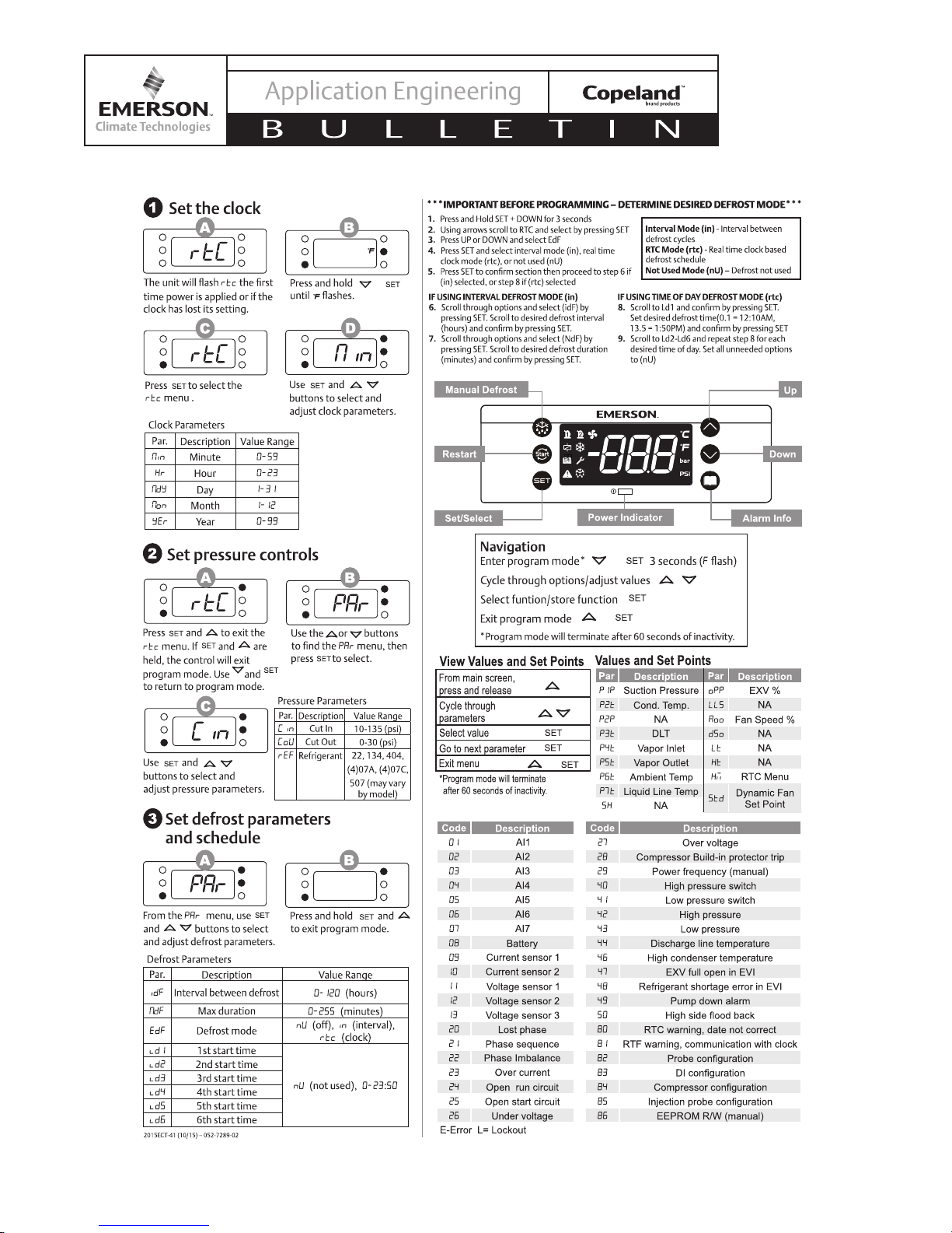
6. User Interface
The controller display is shown below along with the function of each light. The controller displays the current suction
pressure to three digits in pounds per square inch gage (psig). The controller uses a 7-segment display for digits
and the following alpha characters:
The 7-segment alphabet and Roman equivalent:
A b C d E F H i L M n o P q r S T U Y 0 1 2 3 4 5 6 7 8 9
The letters G, J, K, Q, V, W, X and Z are not used on the 7-segment display.
LED MODE FUNCTION
ON Compressor enabled
Flashing Anti-short cycle delay enabled
ON Condensing fans enabled
ON Display temperature value in degrees F
Flashing Programming mode
ON Display pressure value in PSI
ON Browsing service menu
Flashing Fast access menu (Viewing set points and measured values)
ON Browsing the alarm menu
Flashing New alarm occurred
ON An alarm is occurring
ON In defrost or evap fan drip time when ON
ON Evaporator fans enabled
© 2016 Emerson Climate Technologies, Inc.
7

AE5-1412 R1
6.1. Button Descriptions and Key Combinations
(SET) Select a parameter or conrm an
operation when in programming mode.
(RESTART) Hold for 5 seconds to reset
any lockouts if the current state of the
controller allows for reset. Allows a
manual restart and a “dead band reset”.
(UP) View current measured values (Fast
Access Menu); in programming mode or
any menu to browse the parameter codes
or increase the displayed value.
(DOWN) in programming mode or any
menu to browse the parameter codes or
decrease the displayed value.
(SERVICE) To enter the service and
alarm menu.
Hold for 3 seconds to start a manual
defrost
+
Press and hold for about 3 sec to lock
(Pon) or unlock (PoF) the keyboard.
Press together to exit from programming
+
mode or from menu; on submenus to
return to previous level.
+
Press together for 3 sec to access to rst
level of programming mode.
6.2. Changing a Parameter Value
To change a parameter value:
1. Hold down keys for 3 seconds or until
the 'F' LED starts blinking to enter the module’s
programming menu.
2. Use or to select the rtC or PAr menu
3. Press to enter the menu.
4. Use or to select the required parameter.
5. Press the key to display its value.
6. Use or to change its value.
7. Press to store the new value.
TO EXIT: Press or wait 60 seconds
without pressing a key.
NOTE: The set value is stored even when the procedure
is exited by waiting for the time-out to expire.
6.3. Entering the Advanced Options Menu
1. Hold down keys for 3 seconds or
until the F LED starts blinking to enter the module’s
programming menu.
2. Use or to select the PAr menu
3. Press to enter the PAr menu
4. Use or to select the PAS parameter
5. Press to select PAS
6. The blinking PAS label will be showed for a few
seconds
7. Will be showed 0 - - with blinking 0: insert the
password [321] using the keys UP and DOWN and
conrming with SET key.
6.4. Moving Parameters Between the Programming
Menu and the Advanced Options Menu
While in the advanced options menu, certain parameters
will have a (.period) in between the 2nd and 3rd
character, for example Ci.n. These parameters are
in the Programming Menu as well as the Advanced
Options Menu.
To add or remove a parameter from the programming
menu, press the keys together while
the parameter name is on the display in the advanced
options menu. The (.period) between the 2nd and 3rd
parameter will either be added or removed.
TO EXIT: Press or wait 60 seconds
without pressing the keys.
6.5. Locking the Keypad
1. Press the keys for 3 seconds.
2. The POF message will be displayed and the
keyboard will be locked. The Fast Access Menu
will remain accessible whil the keyboard is locked.
3. If a key is pressed more than 3 seconds the POF
message will be displayed.
6.6. Unlocking the Keypad
Press the keys for 3 seconds until the
Pon message is displayed.
NOTE: If a menu does not have any parameters
available, noP will be displayed
© 2016 Emerson Climate Technologies, Inc.
8

AE5-1412 R1
6.7. Changing Clock Setting
+
6.8. Refrigerant Selection
Using parameter REF set the refrigerant as follows
(refer to nameplate for approved refrigerants):
Refrigerant rEF
R-404A 404
R-507 507
R-134A 134
R-22 r22
R-407C 07C
R-407A 07A
R-407F 07F
R-448A 48A
R-449A 49A
6.9. Fast Access Menu
This menu allows viewing measured values from
various probes and view some outputs resulting from
these measurements. The values nP or noP stand for
probe not present or value not evaluated. Err means the
value is out of range, probe is damaged, not connected,
or incorrectly congured.
Press to enter the Fast Access Menu.
Use or arrows to select an entry, then press
to see the value or to go on with other value.
TO EXIT: Press or wait 60 seconds
without pressing the keys.
6.9.1. List of Fast Access Parameters:
P1P Suction pressure
P2t Condenser temperature
P2P Not Used
P3t Discharge line temperature
P4t EVI heat exchanger vapor inlet temperature
(XFAL only)
PSt EVI heat exchanger vapor outlet
temperature (XFAL only)
P6t Ambient temperature
P7t Liquid line temperature (XFAL only)
5H Not used
oPP Percentage of liquid injection (XFAP/
XFAM) or vapor injection (XFAL) valve
opening.
LLS Not used
Std Current condenser temperature target for
fan speed control
A00 Fan speed percent
d5o Not used
L t Not used
H t Not used
tU1 Line voltage (1-phase)
tU2 Line voltage (3-phase)
tU3 Line voltage (3-phase)
tA1 Current (1-phase)
tA2 Current (3-phase)
tA3 Current (3-phase)
HM Menu
© 2016 Emerson Climate Technologies, Inc.
9
AE5-1412 R1
6.10. Alarm Menu
The controller time-stamps and stores the last 50 alarms. See Section 11 for alarm codes.
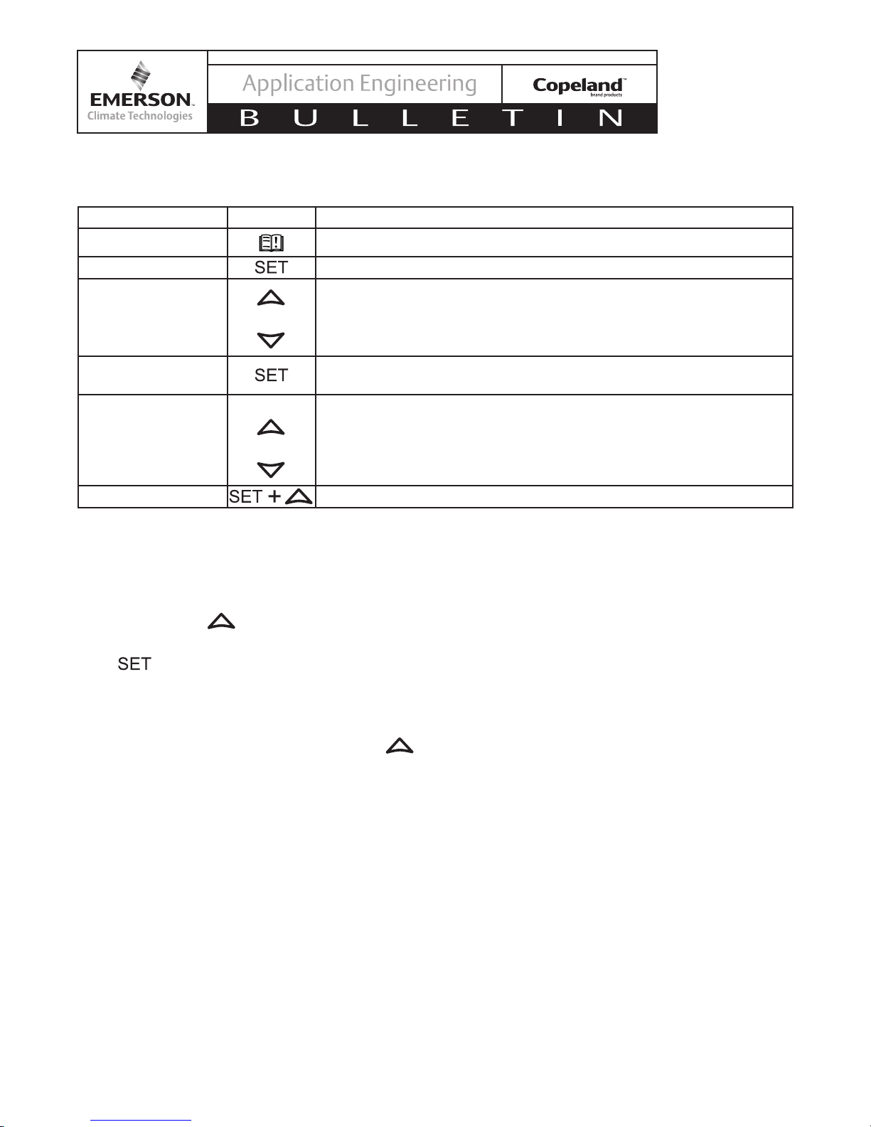
Action Button Notes
Enter alarm menu Push and release alarm key (Displays SEC when alarm menu is active)
Enter alarm list Press SET to conrm
Scroll through active
and recorded alarm
list
Or
Scroll the list of alarms and see the list of active alarms with the number
of the alarm (Letter+Number, A01-A50).
Push Down key and see the alarm Name or Code.
Push Down key and see the next active alarm
Select the alarm to
Enter the sub menu with alarm time details
see the date and time
Scroll through alarm
information data
Or
Successive presses of the down arrow button will display the clock
data label (hour, minute, day, month, year) followed by the value of the
preceding label. The up arrow will reverse this order and show the value
followed by the label. The displayed values record the start time of an
alarm.
Exit menu Press SET and UP together or wait about 10 seconds.
6.11. How to Program a HOT-KEY From the
Controller (UPLOAD TO OVERWRITE HOT-KEY)
Caution: Overwrites hot key. When the controller is ON,
insert the HOT-KEY into the 5-PIN receptacle (labeled
H-K) and push the button; the UPL message
appears followed a by a ashing End label.
Push button and the End will stop ashing.
Turn OFF the controller, remove the HOT-KEY and then
turn the controller ON again.
NOTE: the Err message appears in case of a failed
programming operation. In this case push the
again if you want to restart the upload again or remove
the HOT-KEY to abort the operation.
6.12. How to Program a Controller Using a HOT-KEY
(Download)
A hot key is included with each unit for factory reset
and replacement control programming. Remove power
from the unit.
Insert a pre-programmed HOT-KEY into the 5-PIN
receptacle (labeled H-K) and reapply power to the unit.
The parameter list of the HOT-KEY will be automatically
downloaded into the controller memory. The doL
message will blink followed by a ashing End label.
After 10 seconds the controller will restart and begin
working with the new parameters.
Remove the HOT-KEY
NOTE: The message Err is displayed for failed
programming. In this case turn the unit off and then on
if you want to restart the download again or remove the
HOT-KEY to abort the operation.
6.13. Manual Stepper Control Mode for Vapor
Injection (Low Temp) or Liquid Injection (Medium
Temp)
For troubleshooting purposes, the stepper setting can
temporarily be manually adjusted.
From the standard display screen, pressing SET and
SERVICE/ALARM key for 3 seconds will enter a manual
stepper control mode.
In the manual stepper control mode, the display shows
the current step count of the valve.
In manual stepper control mode, all algorithms
controlling the stepper valve are suspended, but the
rest of the functions operate normally
The up and down arrows on the keypad open and
close the valve, with the display showing the updated
step count
If the controller is left untouched for 60 seconds or
the set and up button are pressed together to exit, the
controller will resume normal operation.
© 2016 Emerson Climate Technologies, Inc.
10
 Loading...