


Control Panel
Operation and Service Manual
1

2
Important Note
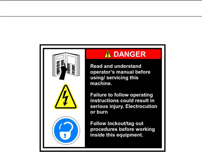
Before applying power to the control panel, all wiring to the panel should be per NEC. Specifically check for proper voltage and that the neutral is grounded at the source. An equipment ground should also be run to the panel.
*See Wiring Instructions and Diagrams before proceeding.
Before start-up you need to enter all system values and options. See section on Setpoint Values.
3

4

Table of Contents |
|
Important Note............................................................................................ |
3 |
Standard Vilter Warranty............................................................................. |
7 |
Operational Flow Charts............................................................................... |
9 |
Installation Recommendations................................................................... |
11 |
Best Practices......................................................................................... |
16 |
Vission 20/20 Architecture......................................................................... |
17 |
Digital Input/Output.............................................................................. |
18 |
Analog Inputs........................................................................................ |
21 |
Analog Outputs..................................................................................... |
23 |
Touch Screen LCD Display........................................................................... |
24 |
Menu Screen.......................................................................................... |
26 |
Compressor Control Screen.................................................................... |
28 |
Pump-Down and Pull-Down Setpoints................................................... |
32 |
Additional Control Setpoints.................................................................. |
34 |
Alarms and Trips Screen......................................................................... |
37 |
Alarms and Trips.................................................................................... |
39 |
Timers................................................................................................... |
41 |
Timers................................................................................................... |
43 |
Service Options...................................................................................... |
44 |
Instrument Calibration........................................................................... |
45 |
Slide Calibration......................................................................................... |
46 |
Command Shaft Rotation....................................................................... |
48 |
Slide Valve Operation................................................................................. |
49 |
Slide Valve Trouble Shooting Guide............................................................. |
50 |
Trend Chart............................................................................................ |
53 |
Event List Screen.................................................................................... |
54 |
Input / Output States............................................................................. |
55 |
Configuration Screens............................................................................ |
56 |
Maintenance Screen.............................................................................. |
59 |
Log In Screen......................................................................................... |
60 |
Screen to Add Users............................................................................... |
61 |
User Security Levels............................................................................... |
62 |
Safety Failure Message........................................................................... |
63 |
Vission 20/20 Troubleshooting Guide......................................................... |
65 |
5

Digital & Analog Boards.............................................................................. |
66 |
Digital Output #1................................................................................... |
67 |
Digital Output #2................................................................................... |
68 |
Digital Input.......................................................................................... |
69 |
Digital Input/Output #1......................................................................... |
70 |
Digital Input/Output #2......................................................................... |
71 |
Analog Input #1..................................................................................... |
72 |
Analog Input #2..................................................................................... |
73 |
Analog Input #3..................................................................................... |
74 |
Analog Input #4..................................................................................... |
75 |
Analog Output....................................................................................... |
76 |
Optional Analog Input Jumper Tables......................................................... |
77 |
6

Standard Vilter Warranty
Seller warrants the products it manufactures to be free from defects in material and workmanship for a period of eighteen (18) months from the date of shipment from Seller’s manufacturing plant or twelve (12) months from date of installation at the initial end users location, whichever occurs first. In addition, Seller provides the following extended warranties: (a) three (3) years from the date of shipment on single screw compressor internal rotating parts, (b) two (2) years from the date of shipment on reciprocating compressors and single screw and reciprocating compressor parts, and (c) two (2) years on all other parts on a single screw compressor unit. Such warranties do not apply to ordinary wear and tear. Seller does not warrant that the product complies with any particular law or regulation not explicitly set forth in the specifications, and Buyer is responsible for ensuring that the product contains all features necessary to safely perform in Buyer’s and its customer’s plants and operations. Buyer must notify Seller of any warranty claim within ten (10) days after such claim arises, otherwise Buyer waives all rights to such claim. Products supplied by Seller, which are manufactured by others, are not warranted by Seller, but rather Seller merely passes through the manufacturer’s warranty to Buyer.
SELLER EXPRESSLY DISCLAIMS ALL OTHER WARRANTIES, WHETHER EXPRESS OR IMPLIED, INCLUDING THE IMPLIED WARRANTIES OF MERCHANTABILITY AND FITNESS FOR A PARTICULAR PURPOSE.
Unless otherwise agreed in writing, Buyer’s sole remedy for breach of warranty is, at Seller’s option, the repair of the defect, the correction of the service, or the providing a replacement part FOB Seller’s office. Seller will not be responsible for costs of dismantling, lost refrigerant, reassembling, or transporting the product. Further, Seller will not be liable for any other direct, indirect, consequential, incidental, or special damages arising out of a breach of warranty. THESE WARRANTY REMEDIES ARE EXCLUSIVE AND ALL OTHER WARRANTY REMEDIES ARE EXCLUDED. Products or parts for which a warranty claim is made are to be returned transportation prepaid to Seller’s factory. Any improper use, corrosion, neglect, accident, operation beyond rated capacity, substitution of parts not approved by Seller, or any alteration or repair by others which, in Seller’s judgement, adversely affects the Product, shall void all warranties and warranty obligations. Further, Seller shall not be liable under the above warranties should Buyer be in default of its payment obligations to Seller under this Agreement or any credit agreement.
7

8

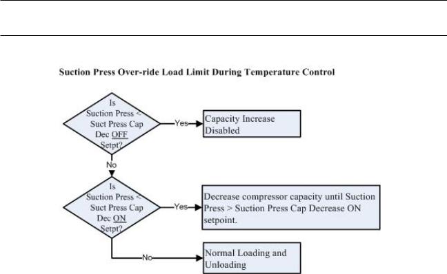
Operational Flow Charts
9
10
Installation Recommendations
Proper Wire Sizing
•As a minimum, always size wire gauges as specified by the National Electrical Code (NEC) for electronic control devices.
•For improved noise immunity, install one size larger wire gauge than the NEC requirement to assure ample current-carrying capability
•Never undersize wire gauges.
Voltage Source
•Transformers block a large percentage of Electro-Magnetic Interference (EMI).
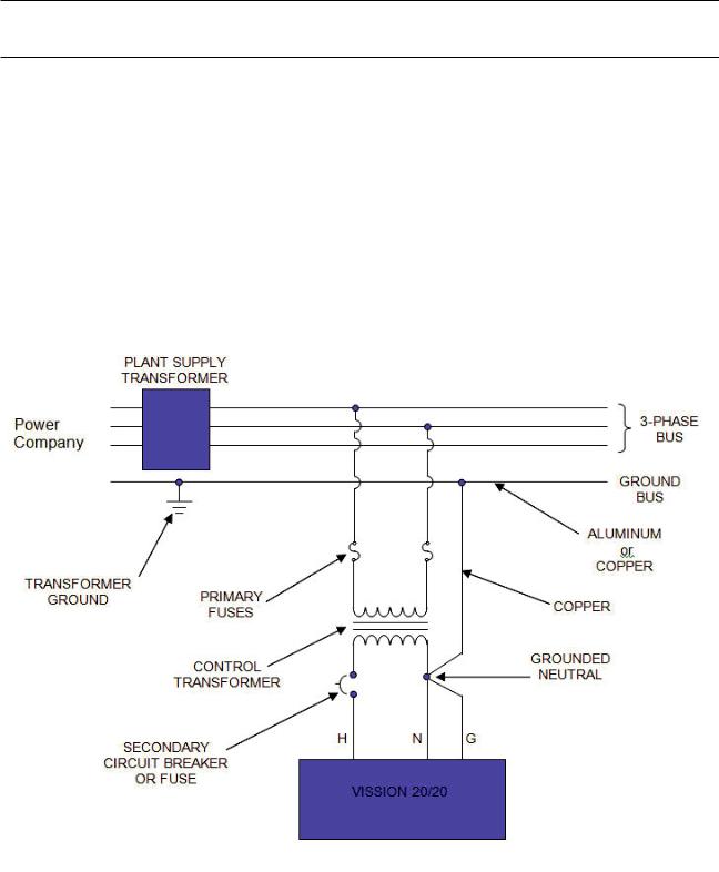
•The Vilter Vission 20/20 should be isolated with its own control transformer, for the most reliable operation.
11
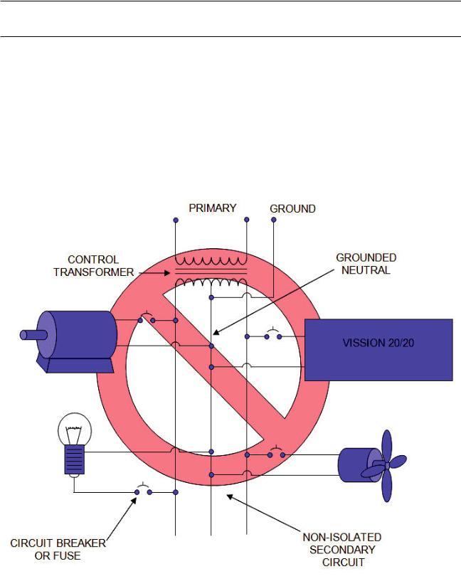
Voltage Source
•Connecting the Vilter Vission 20/20 to breaker panels and central control transformers exposes the Vission 20/20 to large amounts of electromagnetic interference (EMI) emitted from the other devices connected to the secondary terminals of the transformer. This practice should be avoided if possible.
12
Grounding
•Continuous grounds must be run from the power company ground to the Vission 20/20.
•Grounds must be copper or aluminum wire.
•Never use conduit grounds.
13
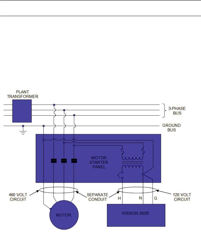
Mixing Voltages
•Separate different voltagesfrom each other and separate AC from DC.
•Each voltage level must be run in separate conduit:
•460 VAC
•230 VAC
•120 VAC
•24 VAC
•DC signals
•If your plant has wire-ways or conduit trays, dividers must be installed between the different voltages.
14

Wiring Methods
•Don’t “Daisy-Chain” control power for Vission 20/20 panels.
15

Best Practices
DO:
•Keep AC wires away from circuit boards.
•Always run conduit into the bottom or sides of an enclosure.
•If the conduit must be placed in the top of an enclosure, use a water-tight conduit fitting to keep water from entering the enclosure.
•The Vission 20/20 is supplied with pre-punched conduit holes. Use them!
DON’T:
•Don’t run wires through the Vission 20/20 enclosure that are not related to the compressor control.
•Don’t add relays, timers, transformers, etc. in the Vission 20/20 enclosure without first checking with Vilter.
•Don’t run conduit into the top of an enclosure.
•Don’t run refrigerant tubing inside the enclosure.
•Don’t drill metal enclosures without taking proper precautions to protect circuit boards from damage.
16
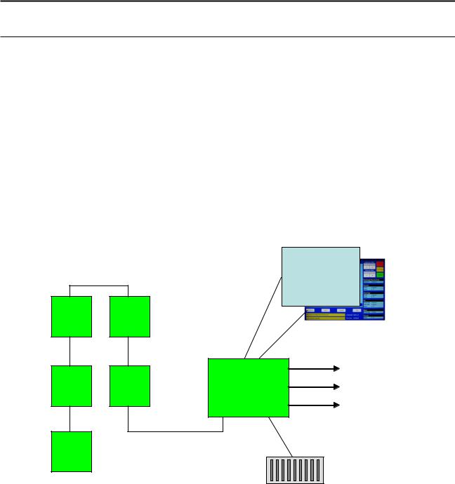
Vission 20/20 Architecture
The Vission 20/20 control panel utilizes X-86 PC technology with a Linux Operating system. The Vission 20/20 has the following attributes:
•Low power, Industrial rated X-86 CPU.
•15” XGA, high resolution LCD display. (Outdoor viewable LCD optional).
•8-wire touch screen operator interface.
•Flexible and expandable I/O.
•NEMA-4 enclosure (NEMA-4X optional).
•Industrial temperature range design.
Touch Screen
I/O |
I/O |
|
LCD DISPLAY |
|
|
|
|
|
|
|
ETHERNET |
I/O |
I/O |
CPU |
RS-485 |
|
|
|
USB |
I/O
DC POWER
17

Digital Input/Output
BOARD |
I/O # |
|
DESCRIPTION |
|
TYPE |
|
|
||||
# |
|
|
|
|
|
1 |
1 |
|
Compressor Start |
|
OUTPUT |
1 |
2 |
|
Oil Pump Start |
|
OUTPUT |
1 |
3 |
|
Capacity Increase |
|
OUTPUT |
1 |
4 |
|
Capacity Decrease |
|
OUTPUT |
1 |
5 |
|
Volume Increase |
|
OUTPUT |
1 |
6 |
|
Volume Decrease |
|
OUTPUT |
1 |
7 |
|
Oil Sump Heater |
|
OUTPUT |
1 |
8 |
|
Alarm |
|
OUTPUT |
2 |
9 |
|
Slide Valve Set point #1 (Economizer) |
|
OUTPUT |
2 |
10 |
|
Slide Valve Set point #2 (Hot Gas) |
|
OUTPUT |
2 |
11 |
|
Slide Valve Set point #3 |
|
OUTPUT |
2 |
12 |
|
Slide Valve Set point #4 |
|
OUTPUT |
2 |
13 |
|
Liquid Injection #1 |
|
OUTPUT |
2 |
14 |
|
Liquid Injection #2 |
|
OUTPUT |
2 |
15 |
|
Remote Enabled |
|
OUTPUT |
2 |
16 |
|
VRS Oil solenoid for old retrofit applications |
|
OUTPUT |
3 |
17 |
|
Comp Motor Starter Auxiliary Contact |
|
INPUT |
3 |
18 |
|
High Level Shutdown |
|
INPUT |
3 |
19 |
|
Oil Level Float Switch #1 |
|
INPUT |
3 |
20 |
|
Oil Level Float Switch #2 |
|
INPUT |
3 |
21 |
|
Remot Setpoint #1/#2 Selection |
|
INPUT |
3 |
22 |
|
Remote Start/Stop |
|
INPUT |
3 |
23 |
|
Remote Capacity Increase |
|
INPUT |
3 |
24 |
|
Remote Capacity Decrease |
|
INPUT |
4 |
25 |
|
Condenser Step #1 |
|
OUTPUT |
4 |
26 |
|
Condenser Step #2 |
|
OUTPUT |
4 |
27 |
|
Condenser Step #3 |
|
OUTPUT |
4 |
28 |
|
Condenser Step #4 |
|
OUTPUT |
4 |
29 |
|
Auxiliary Input #1 |
|
INPUT |
4 |
30 |
|
Auxiliary Input #2 |
|
INPUT |
4 |
31 |
|
Auxiliary Input #3 |
|
INPUT |
4 |
32 |
|
Auxiliary Input #4 |
|
INPUT |
5 |
33 |
|
Auxiliary Output #1 |
|
OUTPUT |
5 |
34 |
|
Auxiliary Output #2 |
|
OUTPUT |
5 |
35 |
|
Auxiliary Output #3 |
|
OUTPUT |
5 |
36 |
|
Auxiliary Output #4 |
|
OUTPUT |
5 |
37 |
|
Auxiliary Input #5 |
|
INPUT |
5 |
38 |
|
Auxiliary Input #6 |
|
INPUT |
5 |
39 |
|
Auxiliary Input #7 |
|
INPUT |
5 |
40 |
|
Auxiliary Input #8 |
|
INPUT |
|
|
|
|
|
|
COMPRESSOR START OUTPUT – When the Vission 20/20 signals the compressor to start, this output is energized. When the Vission 20/20 signals the compressor to stop, this output is de-energized.
OIL PUMP START OUTPUT - When the Vission 20/20 signals the oil pump to start, this output is energized. When the Vission 20/20 signals the oil pump to stop, this output is de-energized.
18

CAPACITY INCREASE OUTPUT – This output is only active when the compressor is running. When the Vission 20/20 determines that the compressor should increase capacity by moving the slide valve to a higher percentage, this output is energized. Once the slide valve reaches 100%, this output will not energize.
CAPACITY DECREASE OUTPUT – This output is only active when the compressor is running. When the Vission 20/20 determines that the compressor should decrease capacity by moving the slide valve to a lower percentage, this output is energized. Once the slide valve reaches 0%, this output will not energize.
VOLUME INCREASE OUTPUT – This output is only active when the compressor is running. When the Vission 20/20 determines that the compressor should increase VI by moving the volume slide to a higher percentage, this output is energized. Once the volume slide reaches 100%, this output will not energize.
VOLUME DECREASE OUTPUT – This output is only active when the compressor is running. When the Vission 20/20 determines that the compressor should decrease VI by moving the volume slide to a lower percentage, this output is energized. Once the volume slide reaches 0%, this output will not energize.
OIL SUMP HEATER OUTPUT – This output is active and energized when the oil separator temperature is lower than the oil separator temperature setpoint. It is de-energized when the oil separator temperature is higher than the oil separator temperature setpoint.
ALARM OUTPUT – This output is energized when the system has no alarms. If an alarm is issued, the output deenergizes and stays de-energized until the alarm condition is cleared.
SLIDE VALVE SETPOINT #1 OUTPUT (ECONOMIZER) – Normally used for an economizer solenoid, but could be used for other devices. When the compressor slide valve percentage is equal to or greater than “slide valve set-point #1”, the output is energized. When the compressor slide valve percentage is less than “slide valve set-point #1”, the output is de-energized.
SLIDE VALVE SETPOINT #2 OUTPUT (HOT GAS) – Normally used for a hot gas solenoid, but could be used for other devices. When the compressor slide valve percentage is equal to or greater than “slide valve set-point #2”, the output is energized. When the compressor slide valve percentage is less than “slide valve set-point #2”, the output is de-energized.
SLIDE VALVE SETPOINT #3 OUTPUT – When the compressor slide valve percentage is equal to or greater than “slide valve set-point #3”, the output is energized. When the compressor slide valve percentage is less than “slide valve set-point #3”, the output is de-energized.
SLIDE VALVE SETPOINT #4 OUTPUT – When the compressor slide valve percentage is equal to or greater than “slide valve set-point #4”, the output is energized. When the compressor slide valve percentage is less than “slide valve set-point #4”, the output is de-energized.
LIQUID INJECTION #1 OUTPUT – If the compressor has liquid injection oil cooling, this output is active. When the compressor is running and the discharge temperature is above the liquid injection temperature control set-point
– 5 degrees, and the oil separator temperature is above the override setpoint, then the output is energized. The output is de-energized when the discharge temperature falls below the “on” setpoint minus the solenoid differential.
LIQUID INJECTION #2 OUTPUT – Not Defined
REMOTE ENABLED OUTPUT – This output is energized when the Vission 20/20 panel is enabled for remote control. The compressor can be running or stopped, but is available to the remote system. If the compressor has an alarm or is placed into the manual stop position, this output is de-energized.
19

VRS OIL SOLENOID OUTPUT – Used in VRS retrofit applications where an oil solenoid is installed in the oil line.
COMP MOTOR STARTER AUXILIARY CONTACT – This input looks for a feedback signal from the compressor starter, confirming that the compressor starter is energized.
HIGH LEVEL SHUTDOWN INPUT – This input must be energized in order for the compressor to operate. If de-ener- gized, the compressor will shut down and issue a high level trip.
OIL LEVEL FLOAT SWITCH #1 INPUT – Used for Cool Compression.
OIL LEVEL FLOAT SWITCH #2 INPUT – Used for Cool Compression.
LOCAL/REMOTE SELECT INPUT – This input enables or disables remote I/O control. Energizing this input enables the Remote Capacity Increase and Remote Capacity Decrease inputs.
REMOTE START/STOP INPUT – If the compressor is enabled for remote I/O control, this input is enabled. Energizing this input will issue a start for the compressor as long as it is available to run. De-energizing this input stops the compressor.
REMOTE CAPACITY INCREASE INPUT – If the compressor is enabled for remote I/O control, this input is enabled. Operational only when the compressor is running. Energizing this input will increase the slide valve position. The slide valve will continuously increase as long as this input is energized. The slide valve will not increase when this input is de-energized.
NOTE: The scan interval on the remote increase and decrease modules is approximately ONE SECOND. Please take that into account when developing a control scheme using the remote increase and remote decrease modules for compressor control.
REMOTE CAPACITY DECREASE INPUT – If the compressor is enabled for remote I/O control, this input is enabled. Operational only when the compressor is running. Energizing this input will decrease the slide valve position. The slide valve will continuously decrease as long as this input is energized. The slide valve will not decrease when this input is de-energized.
CONDENSER STEP #1 OUTPUT – This output is enabled when condenser control option is selected. A condenser fan or pump will be turned on or off by this output.
CONDENSER STEP #2 OUTPUT – This output is enabled when condenser control option is selected. A condenser fan or pump will be turned on or off by this output.
CONDENSER STEP #3 OUTPUT – This output is enabled when condenser control option is selected. A condenser fan or pump will be turned on or off by this output.
CONDENSER STEP #4 OUTPUT – This output is enabled when condenser control option is selected. A condenser fan or pump will be turned on or off by this output.
AUXILIARY #1 thru #8 INPUT – Optional inputs that can be configured as an alarm or trip. Typically connected to external switched devices.
20
Analog Inputs
BOARD |
I/O |
DESCRIPTION |
TYPE |
# |
|
|
|
6 |
1 |
Motor Current |
4-20 mA, 0-5A |
6 |
2 |
Suction Pressure |
0-5V, 1-5 V, 0-10V, 4-20 mA |
6 |
3 |
Discharge Pressure |
0-5V, 1-5 V, 0-10V, 4-20 mA |
6 |
4 |
Oil Filter Pressure |
0-5V, 1-5 V, 0-10V, 4-20 mA |
6 |
5 |
Oil Manifold Pressure |
0-5V, 1-5 V, 0-10V, 4-20 mA |
6 |
6 |
VRS Oil Injection Pressure |
0-5V, 1-5 V, 0-10V, 4-20 mA |
6 |
7 |
% slide Valve Position |
0-5V, 4-20 mA, Potentiometer |
6 |
8 |
% Volume Position |
0-5V, 4-20 mA, Potentiometer |
7 |
9 |
Suction Temperature |
4-20 mA, RTD, ICTD |
7 |
10 |
Discharge Temperature |
4-20 mA, RTD, ICTD |
7 |
11 |
Oil Separator Temperature |
4-20 mA, RTD, ICTD |
7 |
12 |
Oil Manifold Temperature |
4-20 mA, RTD, ICTD |
7 |
13 |
Process Temperature |
4-20 mA, RTD, ICTD |
7 |
14 |
Level Probe (Cool Compression) |
4-20 mA |
7 |
15 |
Condenser Pressure |
0-5V, 1-5 V, 0-10V, 4-20 mA |
7 |
16 |
Remote Set point |
0-5V, 4-20 mA |
8 |
17 |
Economizer Pressure |
0-5V, 1-5 V, 0-10V, 4-20 mA |
8 |
18 |
Chiller In Temperature |
4-20 mA, RTD, ICTD |
8 |
19 |
Motor Winding Temperature #1 |
4-20 mA, RTD |
8 |
20 |
Motor Winding Temperature #2 |
4-20 mA, RTD |
8 |
21 |
Motor Winding Temperature #3 |
4-20 mA, RTD |
8 |
22 |
Auxiliary #1 |
0-5V, 1-5V, 0-10V, 4-20 mA, RTD, ICTD |
8 |
23 |
Auxiliary #2 |
0-5V, 1-5V, 0-10V, 4-20 mA, RTD, ICTD |
8 |
24 |
Auxiliary #3 |
0-5V, 1-5V, 0-10V, 4-20 mA, RTD, ICTD |
9 |
25 |
Auxiliary #4 |
0-5V, 1-5V, 0-10V, 4-20 mA, RTD, ICTD |
9 |
26 |
Auxiliary #5 |
0-5V, 1-5V, 0-10V, 4-20 mA, RTD, ICTD |
9 |
27 |
Auxiliary #6 |
0-5V, 1-5V, 0-10V, 4-20 mA, RTD, ICTD |
9 |
28 |
Auxiliary #7 |
0-5V, 1-5V, 0-10V, 4-20 mA, RTD, ICTD |
9 |
29 |
Bearing Accelerometer/Temp #1 |
0-5V, 4-20 mA, RTD |
9 |
30 |
Bearing Accelerometer/Temp #2 |
0-5V, 4-20 mA, RTD |
9 |
31 |
Bearing Accelerometer/Temp #3 |
0-5V, 4-20 mA, RTD |
9 |
32 |
Bearing Accelerometer/Temp #4 |
0-5V, 4-20 mA, RTD |
|
|
|
|
MOTOR CURRENT – Default is a 0-5 Amp current transformer (CT). Current transformer ratio is set in the calibration screen.
SUCTION PRESSURE – Default signal is 4-20Ma. Suction pressure transducer range and calibration is set in the calibration screen.
DISCHARGE PRESSURE - Default signal is 4-20Ma. Discharge pressure transducer range and calibration is set in the calibration screen.
OIL FILTER PRESSURE - Default signal is 4-20Ma. Oil filter pressure transducer range and calibration is set in the calibration screen.
21

OIL MANIFOLD PRESSURE - Default signal is 4-20Ma. Oil manifold pressure transducer range and calibration is set in the calibration screen.
VRS OIL INJECTION PRESSURE – Default signal is 4-20Ma. VRS oil injection pressure transducer range and calibration is set in the calibration screen.
%SLIDE VALVE POSITION – Reads the 0-5 volt signal back from the slide position motor actuator to indicate current slide valve position.
%VOLUME POSITION – Reads the 0-5 volt signal back from the slide volume motor actuator to indicate current volume position.
SUCTION TEMPERATURE – Default signal is RTD. Suction temperature calibration is set in the calibration screen.
DISCHARGE TEMPERATURE – Default signal is RTD. Discharge temperature calibration is set in the calibration screen.
OIL SEPARATOR TEMPERATURE – Default signal is RTD. Oil separator temperature calibration is set in the calibration screen.
OIL MANIFOLD TEMPERATURE – Default signal is RTD. Oil manifold temperature calibration is set in the calibration screen.
PROCESS TEMPERATURE – Default signal is RTD. Process temperature calibration is set in the calibration screen.
LEVEL PROBE (COOL COMPRESSION) – Default signal is 4-20mA. Measures separator level. Level probe calibration is set in the calibration screen.
CONDENSER PRESSURE – Default signal is 4-20Ma. Condenser pressure transducer range and calibration is set in the calibration screen.
REMOTE CAPHOLD – Default signal is 4-20Ma. Active in “Direct I/O” mode. Adjusts the capacity of the compressor from 0-100%, proportional to the 4-20mA signal.
ECONOMIZER PRESSURE – Default signal is 4-20Ma. Economizer pressure transducer range and calibration is set in the calibration screen.
CHILLER IN TEMPERATURE – Default signal is RTD. Chiller inlet temperature calibration is set in the calibration screen.
MOTOR WINDING TEMPERATURE #1 thru #3 - Default signal is RTD. One RTD is installed in each of the three motor windings to monitor motor winding temperature.
AUXILIARY #1 thru #7 – Flexible analog inputs that can be configured to control, alarm or trip.
BEARING TEMP #1 thru #4 - Default signal is RTD. Monitors bearing temperatures in both the compressor and motor.
22

Analog Outputs
BOARD |
I/O # |
DESCRIPTION |
TYPE |
# |
|
|
|
10 |
1 |
Compressor VFD |
4-20 mA |
10 |
2 |
Condenser VFD |
4-20 mA |
10 |
3 |
% Slide Valve Position |
4-20 mA |
10 |
4 |
Motorized Valve (Cool Compression or Liquid Injection), V+ |
4-20 mA |
10 |
5 |
Profile Cooler VFD (Profile only) |
4-20 mA |
10 |
6 |
|
|
10 |
7 |
|
|
10 |
8 |
|
|
|
|
|
|
COMPRESSOR VFD – 4-20mA output to control compressor motor speed with a Variable Frequency Drive (VFD).
CONDENSER VFD – 4-20mA output to control one condenser fan which is interleaved between the remaining condenser steps for smoother control.
% SLIDE VALVE POSITION – 4-20mA signal that transmits the slide valve position for remote monitoring.
MOTORIZED VALVE (V+) – for a cool compression compressor, this 4-20ma signal controls a motorized valve to regulate the liquid refrigerant level in the oil separator. For a liquid injection application on a standard single screw, this 4-20ma signal controls a motorized valve to regulate the liquid refrigerant injected into the compressor for oil cooling purposes.
PROFILE VFD – for a profile unit compressor, this signal controls the aftercooler fan speed which provides oil cooling.
23
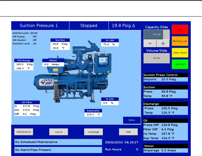
Touch Screen LCD Display
Main Screen
The main screen gives the operator an overall view of operating parameters affecting the compressor package. This screen is displayed when maintenance items and set-points items are not being performed. The data on the screen is continuously updated.
Menu Button
Navigates to the menu screen for the following selections:
• |
Compressor Control |
• |
Instrument Calibration |
• |
Alarms and Trips |
• |
Slide Calibration |
• |
Timers |
• |
Trend Chart |
• |
Compressor Scheduling |
• |
Event List |
• |
Compressor Sequencing |
• |
Input/Output States |
• |
Condenser Control |
• |
Configuration |
• |
Service Options |
• |
Data Backup |
MAINTENANCE BUTTON
Navigates to the maintenance screen to allow an operator to see interval times for maintenance items and to log completed maintenance items.
24
 Loading...