

Page 1
Embedded Power for
Business-Critical Continuity
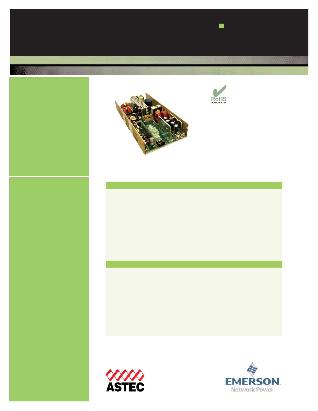
LPS170-M Series
Medical
175 Watts
Special Features
• Medical safety approvals
• Active power factor correction
• IEC EN61000-3-2 compliance
• Wide Range Adjustable output
Remote sense on main output
• Single wire current sharing
• Power fail and remote inhibit
• Built-in EMI filter
• Low output ripple
• Overvoltage protection
• Overload protection
• Thermal overload protection
• DC power good
• 5 V standby output
• 12 V Aux output
• Optional cover (-C suffix)
Total Power: 100 - 175 Watts
Input Voltage: 85-264 VAC
120-300 VDC
# of Outputs: Single
Electrical Specifications
Safety
Input
Input ra nge 85-264 VAC; 120-300 VDC
Frequency 47-67 Hz
Inrush current 38 A max, cold start @ 25°C
Efficiency 75% typical at full load
EMI filter FCC Class B conducted
CISPR 22 Class B conducted
EN55022 Class B conducted
VDE 0878 PT3 Class B conducted
Power Factor 0.99 typical
Safety ground
leakage current
<250 μA @ 50/60 Hz, 264 VAC inputS
Output
Maximum power 110 W convection (75 W with cover)
175 W with 30 CFM forced air
(130 W with cover)
Adjustment range 2:1 wide ratio minimum
Standby outputs 5 V @ 2 A regulated ±5%
Hold-up time 20 ms @175 W load at nominal line
Overload protection Short circuit protection on all outputs.
Case overload protected @ 110-145% above peak rating
Overvoltage protection 10% to 40% above nominal output
Aux output 12 V @ 1 A -5 %, +10%
VDE 0750/EN60601-1 (IEC601)
UL UL2601
CSA CSA 22.2 No. 601.1
CE Mark (LVD)
Rev. 08.07.07
LPS170-M Series
1 of 3
Page 2

Embedded Power for
Business-Critical Continuity
Ordering Information
Model
Number
Output
Voltage
Minimum
Load
Maximum Load with
Convection Cooling
Maximum
Load with
30CFM
forced Air Peak Load 1Regulation
2
Ripple P/P
(PARD)
3
LPS172-M 5 V (2.5 - 6 V) 0 A 22 A 35 A 38 A ±2% 50 mV
LPS173-M 12 V (6 - 12 V) 0 A 9.1 A 15 A 16.5 A ±2% 120 mV
LPS174-M 15 V (12 - 24 V) 0A 7.3 A 12 A 13.2 A ±2% <1%
LPS175-M 24 V (24 - 54 V) 0A 4.5 A 7.5 A 8.2 A ±2% <1%
1. Peak current lasting <30 seconds with a maximum 10% duty cycle.
2. At 25°C including initial tolerance, line voltage, load currents and output voltages adjusted to factory settings.
3. Peak-to-peak with 20 MHz bandwidth and 10 μF in parallel with a 0.1 μF capacitor at rated line voltage and load
ranges.
4. Remote inhibit resets OVP latch.
Note: -C suffix added to the model number indicates cover option.
Rev. 08.07.07
LPS170-M Series
2 of 3
Operating temperature: 0° to 50°C ambient;
derate each output at 2.5% per degree from 50° to 70°C
Storage temperature: -40°C to +85°C
Temperature coefficient:
±0.4% per °C
Storage temperature: -40° to 85°C
Electromagnetic
susceptibility: Designed to meet IEC EN61000-4, -2, -3, -4, -5, -6, -8, -11 Level 3
Humidity: Operating; non-condensing 5% to 95%
Vibration: Three orthogonal axes, sweep at 1 oct/min, 5 min. dwell at four
major resonances 0.75G peak 5Hz to 500Hz, operational
MTBF demonstrated: >550,000 hours at full load and 25°C ambient conditions
Environmental Specifications
Logic Control
Power failure
TTL logic signal goes high 100 - 500 msec after V1 output; It
goes low at least 4 msec before loss of regulation
Remote inhibit Requires contact closure to inhibit outputs
Remote sense
Compensates for 0.5 V lead drop min. Will operate without
remote sense connected. Reverse connection protected.
DC - OK
TTL logic signal goes high after main output is in regulation. It
goes low when there is a loss of regulation
Mating Connectors
(SK4) AC Input: Molex 09-50-8051 (USA)
Molex 09-91-0500 (UK)
PINS: 08-58-0111
(SK3) DC Output:
Molex 19141-0058
(SK1) Control Signals:
Molex 90142-0010 (USA)
PINS: 90119-2110 or
Amp: 87977-3
PINS: 87309-8
Astec connector kit #70-841-016
Notes:
1. Specifications subject to change without notice.
2. All dimensions in inches (mm), tolerance is ±0.02”.
3. Specifications are for convection rating at factory settings unless
otherwise stated.
4. Mounting screw maximum insertion depth is 0.12”.
5. Warranty: 2 year
6. Weight: 1.8 lb / 0.85 kg
Pin Assignments
Connector LPS17x
SK1 PIN 1 +12 V
PIN 2 5 V Standby
Pin 3 Common
Pin 4 V1 SWP
PIN 5 Common
PIN 6 +V1 sense
PIN 7 Sense common
PIN 8 Remote inhibit
PIN 9 DC poer good
PIN 10 POK
SK2
TB-1 COMMON
TB-2 Main output
SK3
PIN 1 GROUND
PIN 2 LINE
Pin 5 NEUTRAL
Page 3

Emerson Network Power and the Emerson
Network Power logo are trademarks and
service marks of Emerson Electric Co.
©2007 Emerson Electric Co.
Embedded Power for
Business-Critical Continuity
Emerson Network Power.
The global leader in enabling
business-critical continuity.
EmersonNetworkPower. com
AC Power
Connectivity
DC Power
Embedded Power
Inbound Power
Integrated Cabinet Solutions
Outside Plant
Precision Cooling
Site Monitoring and Services
Americas
5810 Van Allen Way
Carlsbad, CA 92008
USA
Telephone: +1 760 930 4600
Facsimile: +1 760 930 0698
Europe (UK)
Waterfront Business Park
Merry Hill, Dudley
West Midlands, DY5 1LX
United Kingdom
Telephone: +44 (0) 1384 842 211
Facsimile: +44 (0) 1384 843 355
Asia (HK)
16th - 17th Floors, Lu Plaza
2 Wing Yip Street, Kwun Tong
Kowloon, Hong Kong
Telephone: +852 2176 3333
Facsimile: +852 2176 3888
For global contact, visit:
www.astecpower.com
www.artesyn.com
technicalsupport@astec.com
technicalsupport@artesyn.com
While every precaution has been taken to ensure
accuracy and completeness in this literature, Emerson
Network Power assumes no responsibility, and disclaims
all liability for damages resulting from use of this
information or for any errors or omissions.
Rev. 08.07.07
LPS170-M Series
3 of 3
Mechanical Drawing
 Loading...