


Epsilon Eb Digital Servo Drive
Installation Manual
P/N: 400501-05
Revision: A2
Date: October 1, 2001
© Control Techniques Drives, Inc. 2000, 2001

Epsilon Eb
Digital Servo Drive
Installation Manual
Information furnished by Control Techniques Drives Inc. (Control Techniques) is believed to be accurate and reliable. However, no responsibility is assumed by Control Techniques for its use. Control Techniques reserves the right to change the design or operation of the equipment described herein and any associated motion products without notice. Control Techniques also assumes no responsibility for any errors that may appear in this document. Information in this document is subject to change without notice.
P/N: 400501-05
Revision: A2
Date: October 1, 2001
© Control Techniques Drives, Inc. 2000, 2001

© Control Techniques Drives, Inc. 2000, 2001
Part Number: 400501-05 Revision: A2
Date: October 1, 2001
Printed in United States of America
Information in this document is subject to change without notice. No part of this document may be reproduced or transmitted in any form or by any means, electronic or mechanical, for any purpose, without the express written permission of Control Techniques.
The following are trademarks of Control Techniques and may not be reproduced in any fashion without written approval of Control Techniques: EMERSON Motion Control, EMERSON Motion Control Power Tools, AXIMA, “Motion Made Easy.”
Control Techniques is a divison of EMERSON Co.
Control Techniques, Inc. is not affliated with Microsoft Corporation, over of hte Microsoft, Windows, and Windows NT trademarks.
IBM is a registered trademark of International Business Machines Corportation. Modbus is a registered trademark of Gould, Inc.
Data Highway Plus is a trademark of Allen-Bradley Schaffner is a trademark of Schaffner.
DeviceNet is a trademark of Open DeviceNet Vendor Association.
This document has been prepared to conform to the current released version of theproduct. Because of our extensive development efforts and our desire to further improve and enhance the product, inconsistencies may exist between the product and documentation in some instances. Call your customer support representative if you encounter an inconsistency.
ii

Customer Service
Control Techniques
12005 Technology Drive
Eden Prairie, Minnesota 55344-3620 U.S.A.
Telephone: (952) 995-8000 or (800) 397-3786
It is Control Techniques’ goal to ensure your greatest possible satisfaction with the operation of our products. We are dedicated to providing fast, friendly, and accurate assistance. That is why we offer you so many ways to get the support you need. Whether it’s by phone, fax or modem, you can access Control Techniques support information 24 hours a day, seven days a week. Our wide range of services include:
FAX |
(952) 995-8011 |
You can FAX questions and comments to Control Techniques. Just send a FAX to the number listed above.
Website and Email |
www.emersonct.com |
Website: www.emersonct.com Email: info@emersonct.com
If you have Internet capabilities, you also have access to technical support using our website. The website includes technical notes, frequently asked questions, release notes and other technical documentation. This direct technical support connection lets you request assistance and exchange software files electronically.
Technical Support |
(952) 995-8033 or (800) 397-3786 |
Email: service@emersonct.com
Control Techniques’ “Motion Made Easy” products are backed by a team of professionals who will service your installation wherever it may be. Our technical service center in Eden Prairie, Minnesota is ready to help you solve those occasional problems over the telephone. Our technical service center is available 24 hours a day for emergency service to help speed any problem solving. Also, all hardware replacement parts, should they ever be needed, are available through our service organization.
When you call, please be at your computer, have your documentation in hand, and be prepared to provide the following information:
•Product version number, found by choosing About from the Help menu.
•The type of controller or product you are using.
iii

•Exact wording of any messages that appear on your screen.
•What you were doing when the problem occurred.
•How you tried to solve the problem.
Need on-site help? Control Techniques provides service, in most cases, the next day. Just call Control Techniques’ technical service center when on-site service or maintenance is required.
Training Services |
(952) 995-8000 or (800) 397-3786 |
Email: training@emersonct.com
Control Techniques maintains a highly trained staff of instructors to familiarize customers with Control Techniques’ “Motion Made Easy” products and their applications. A number of courses are offered, many of which can be taught in your plant upon request.
Application Engineering |
(952) 995-8000 or (800) 397-3786 |
Email: applengr@emersonct.com
An experienced staff of factory application engineers provides complete customer support for tough or complex applications. Our engineers offer you a broad base of experience and knowledge of electronic motion control applications.
Customer Service (Sales) |
(952) 995-8000 or (800) 397-3786 |
Email: sales@emersonct.com
Authorized Control Techniques distributors may place orders directly with our Customer Service department. Contact the customer Service department at this number for the distributor nearest you.
Document Conventions
Manual conventions have been established to help you learn to use this manual quickly and easily. As much as possible, these conventions correspond to those found in other
MicrosoftÒ WindowsÒ documentation.
Menu names and options are printed in bold type: the File menu.
Dialog box names begin with uppercase letters: the Axis Limits dialog box. Dialog box field names are in quotes: “Field Name.”
Button names are in italic: OK button.
Source code is printed in Courier font: Case ERMS.
iv
In addition, you will find the following typographic conventions throughout this manual.
This |
Represents |
|
Characters that you must type exactly as they appear. For example, if |
bold |
you are directed to type a:setup, you should type all the bold characters |
|
exactly as they are printed. |
|
|
|
Place holders for information you must provide. For example, if you are |
italic |
directed to type filename, you should type the actual name for a file |
|
instead of the word shown in italic type. |
|
|
ALL CAPITALS |
Directory names, file names, key names, and acronyms. |
|
|
SMALL CAPS |
Non-printable ASCII control characters. |
|
|
KEY1+KEY2 |
A plus sign (+) between key names means to press and hold down the |
example: (Alt+F) |
first key while you press the second key. |
|
|
KEY1,KEY2 |
A comma (,) between key names means to press and release the keys one |
example: (Alt,F) |
after the other. |
|
|
Note
For the purpose of this manual and product, “Note” indicates essential information about the product or the respective part of the manual.
Epsilon Only
For the purpose of this manual and product, the “Epsilon” symbol indicates information about the Epsilon drive specifically.
Throughout this manual, the word “drive” refers to an Epsilon or E Series drive.
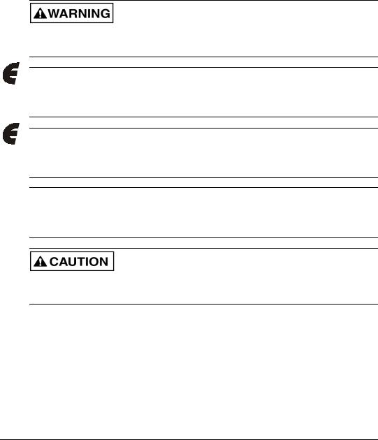
“Warning” indicates a potentially hazardous situation that, if not avoided, could result in death or serious injury.
“Caution” indicates a potentially hazardous situation that, if not avoided, may result in minor or moderate injury.
“Caution” used without the safety alert symbol indicates a potentially hazardous situation that, if not avoided, may result in property damage.
v

Safety Instructions
General Warning
Failure to follow safe installation guidelines can cause death or serious injury. The voltages used in the product can cause severe electric shock and/or burns and could be lethal. Extreme care is necessary at all times when working with or adjacent to the product. The installation must comply with all relevant safety legislation in the country of use.
Qualified Person
For the purpose of this manual and product, a “qualified person” is one who is familiar with the installation, construction and operation of the equipment and the hazards involved. In addition, this individual has the following qualifications:
•Is trained and authorized to energize, de-energize, clear and ground and tag circuits and equipment in accordance with established safety practices.
•Is trained in the proper care and use of protective equipment in accordance with established safety practices.
•Is trained in rendering first aid.
Reference Materials
The following related reference and installation manuals may be useful with your particuliar system.
•Epsilon Eb and E Series En Drives Reference Manual (P/N 400501-01)
•PowerTools Software User’s Guide (P/N 400503-01)
•Epsilon and E Series Drive Parameters Reference Manual (P/N 400504-01)
vi

Safety Considerations
Safety Precautions
This product is intended for professional incorporation into a complete system. If you install the product incorrectly, it may present a safety hazard. The product and system may use high voltages and currents, carry a high level of stored electrical energy, or are used to control mechanical equipment that can cause injury.
You should give close attention to the electrical installation and system design to avoid hazards either in normal operation or in the event of equipment malfunction. System design, installation, commissioning and maintenance must be carried out by personnel who have the necessary training and experience. Read and follow this safety information and instruction manual carefully.
Enclosure
This product is intended to be mounted in an enclosure that prevents access except by trained and authorized personnel and prevents the ingress of contamination. This product is designed for use in an environment classified as pollution degree 2 in accordance with IEC664-1. This means that only dry, non-conducting contamination is acceptable.
Setup, Commissioning and Maintenance
It is essential that you give careful consideration to changes to drive settings. Depending on the application, a change could have an impact on safety. You must take appropriate precautions against inadvertent changes or tampering. Restoring default parameters in certain applications may cause unpredictable or hazardous operation.
Safety of Machinery
Within the European Union all machinery in which this product is used must comply with Directive 89/392/EEC, Safety of Machinery.
The product has been designed and tested to a high standard, and failures are very unlikely. However the level of integrity offered by the product’s control function – for example stop/ start, forward/reverse and maximum speed – is not sufficient for use in safety-critical applications without additional independent channels of protection. All applications where malfunction could cause injury or loss of life must be subject to a risk assessment, and further protection must be provided where needed.
General warning
Failure to follow safe installation guidelines can cause death or serious injury. The voltages used in this unit can cause severe electric shock and/or burns, and could be lethal. Extreme care is necessary
vii

Epsilon Eb Digital Servo Drive Installation Manual
at all times when working with or adjacent to this equipment. The installation must comply with all relevant safety legislation in the country of use.
AC supply isolation device
The AC supply must be removed from the drive using an approved isolation device or disconnect before any servicing work is performed, other than adjustments to the settings or parameters specified in the manual. The drive contains capacitors which remain charged to a potentially lethal voltage after the supply has been removed. Allow at least 6 minutes for the Epsilon 205, 3 minutes for Epsilon 202/203 and 30 seconds for E Series drives after removing the supply before carrying out any work which may involve contact with electrical connections to the drive.
Products connected by plug and socket
A special hazard may exist where the drive is incorporated into a product which is connected to the AC supply by a plug and socket. When unplugged, the pins of the plug may be connected to the drive input, which is only separated from the charge stored in the bus capacitor by semiconductor devices. To avoid any possibility of electric shock from the pins, if they are accessible, a means must be provided for automatically disconnecting the plug from the drive (e.g., a latching contactor).
Grounding (Earthing, equipotential bonding)
The drive must be grounded by a conductor sufficient to carry all possible fault current in the event of a fault. The ground connections shown in the manual must be followed.
Fuses
Fuses or over-current protection must be provided at the input in accordance with the instructions in the manual.
Isolation of control circuits
The installer must ensure that the external control circuits are isolated from human contact by at least one layer of insulation rated for use at the applied AC supply voltage.
viii
Underwriters Laboratories Listed
LISTED 51Y8
IND. CONT. EQ.
The Epsilon Digital Servo Drives are marked with the “UL Listed” label after passing a rigorous set of design and testing criteria developed by UL (UL508C). This label indicates that UL certifies this product to be safe when installed according to the installation guidelines and used within the product specifications.
The “conditions of acceptability” required by UL are:
•The Epsilon drive surrounding air ambient temperature must be 40° C (104° F) or less.
•Epsilon drive surrounding air ambient temperature can be up to 50°C (122° F) with 3% linear derating for every degree above 40° C (104° F).
•This product is suitable for use on a circuit of delivering not more than 5000 RMS symmetrical amperes, 240 volts maximum.
•Motors must incorporate an overload protection device such as an overtemperature switch.
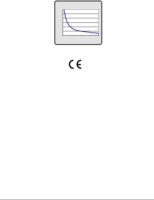
Drive Overload Protection
The drive output current overload protection is provided by the drive and is not adjustable. This overload protection is based on maximum continuous output current capacity. It will allow up to 200 percent of the drive rated current to be delivered for the amount of time determined by the following chart.
Rated output current (Amps RMS)
Drive Model |
Continuous |
Peak |
|
|
|
Eb-202 |
1.8 |
3.6 |
|
|
|
Eb-203 |
3 |
6 |
|
|
|
Eb-205 |
5.0 |
10.0 |
|
|
|
ix
Drive Output Current vs. Time graph
|
60 |
|
|
|
|
|
50 |
|
|
|
|
(seconds) |
40 |
|
|
|
|
30 |
|
|
|
|
|
|
|
|
|
|
|
Time |
20 |
|
|
|
|
|
|
|
|
|
|
|
10 |
|
|
|
|
|
0 |
|
|
|
|
|
100 |
125 |
150 |
175 |
200 |
% Drive Rated Current
CE Declaration of Conformity
The Epsilon Digital Servo Drives are marked with the “Conformite Europeenne Mark” (CE mark) after passing a rigorous set of design and testing criteria. This label indicates that this product meets safety and noise immunity and emissions (EMC) standards when installed according to the installation guidelines and used within the product specifications.
x

|
Declaration of Conformity |
|
Manufacturer’s Name: |
Control Techniques |
|
|
12005 Technology Drive |
|
Manufacturer’s Address: |
Eden Prairie, MN 55344 |
|
|
USA |
|
|
Declares that the following products: |
|
Products Description: |
Epsilon Digital Servo Drive |
|
Model Number: |
Eb-202, Ei-202, Eb-203, Ei-203, Eb-205 and Ei-205 |
|
System Options: |
This declaration covers the above products with the ECI-44 Screw |
|
Terminal Interface. |
||
|
Conforms to the following product specification:
Electomagnetic Compatibility (EMC):
EN 55011/1991 Class A Group 1, CISPR 11/1990 Class A Group 1
|
IEC 1000-4-2/1995; EN 61000-4-2, 6kV CD |
|
|
IEC 1000-4-3/1995; EN 61000-4-3, ENV 50140/1993, 80% AM, |
|
EN 61800-3, 1996: |
10V/m @ 3 m |
|
IEC 1000-4-4/1995; EN 61000-4-4, 2 kV ALL LINES |
||
|
||
|
EN 61000-4-5, 1kV L-L, 2kV L-G |
|
|
EN 61000-4-11, 300 ms/1000 ms 100% DIP |
|
|
ENV 50204/1995, Pulse, 900 MHz, 50% DTY, 200 Hz |
Supplementary information:
The products herewith comply with the requirements of the Low Voltage Directive (LVD) 73/23/EEC and EMC Directive 89/336/EEC
This electronic drive product is intended to be used with an appropriate motor, electrical protection components and other equipment to form a complete end product or system. It must only be installed by a professional assembler who is familiar with requirements for safety and electromagnetic compatibility (“EMC”). The assembler is
responsible for ensuring that the end product or system complies with all the relevant laws in the country where it is |
|
to be used. Refer to the product manual for installation guidelines. |
|
|
August 18, 1999 |
Bradley Schwartz/ VP Engineering |
Date |
|
|
|
Sobetra Automation |
European Contact: |
Langeveldpark Lot 10 |
|
P. Dasterleusstraat 2 |
||
|
||
|
1600 St. Pieters Leeuw, Belgium |
|
|
|
xi

xii

Table of Contents
Reference Materials . . . . . . . . . . . . . . . . . . . . . . . . . . . . . . . . . . . . . . . . . . . . . . . . . . . . . . . . . . . vi
Safety Considerations
Safety Precautions . . . . . . . . . . . . . . . . . . . . . . . . . . . . . . . . . . . . . . . . . . . . . . . . . . . . . . . . vii Enclosure . . . . . . . . . . . . . . . . . . . . . . . . . . . . . . . . . . . . . . . . . . . . . . . . . . . . . . . . . . . . . . . vii Setup, Commissioning and Maintenance . . . . . . . . . . . . . . . . . . . . . . . . . . . . . . . . . . . . . . . vii Safety of Machinery . . . . . . . . . . . . . . . . . . . . . . . . . . . . . . . . . . . . . . . . . . . . . . . . . . . . . . . vii
. . . . . . . . . . . . . . . . . . . . . . . . . . . . . . . . . . . . . . . . . . . . . . . . . . . . . . . . . . . . . . . . . . . . . . viii
Introduction
Epsilon Eb Digital Servo Drive . . . . . . . . . . . . . . . . . . . . . . . . . . . . . . . . . . . . . . . . . . . . . . . . . . . 1
Features . . . . . . . . . . . . . . . . . . . . . . . . . . . . . . . . . . . . . . . . . . . . . . . . . . . . . . . . . . . . . . . . . . . . . 1
Installation
Basic Installation Notes . . . . . . . . . . . . . . . . . . . . . . . . . . . . . . . . . . . . . . . . . . . . . . . . . . . . . . . . . 3
Electromagnetic Compatibility (EMC) . . . . . . . . . . . . . . . . . . . . . . . . . . . . . . . . . . . . . . . . . 3
Environmental Considerations . . . . . . . . . . . . . . . . . . . . . . . . . . . . . . . . . . . . . . . . . . . . . . . . 7
Wiring Notes . . . . . . . . . . . . . . . . . . . . . . . . . . . . . . . . . . . . . . . . . . . . . . . . . . . . . . . . . . . . . 8
Mechanical Installation . . . . . . . . . . . . . . . . . . . . . . . . . . . . . . . . . . . . . . . . . . . . . . . . . . . . . . . . . 8
Drive Mounting . . . . . . . . . . . . . . . . . . . . . . . . . . . . . . . . . . . . . . . . . . . . . . . . . . . . . . . . . . . 8
Motor Mounting . . . . . . . . . . . . . . . . . . . . . . . . . . . . . . . . . . . . . . . . . . . . . . . . . . . . . . . . . . . 8
Electrical Installation. . . . . . . . . . . . . . . . . . . . . . . . . . . . . . . . . . . . . . . . . . . . . . . . . . . . . . . . . . . 9
Power Supply Requirements . . . . . . . . . . . . . . . . . . . . . . . . . . . . . . . . . . . . . . . . . . . . . . . . 10
Transformer Sizing. . . . . . . . . . . . . . . . . . . . . . . . . . . . . . . . . . . . . . . . . . . . . . . . . . . . . . . . 13
Line Fusing and Wire Size . . . . . . . . . . . . . . . . . . . . . . . . . . . . . . . . . . . . . . . . . . . . . . . . . . 14
Input Power Connections . . . . . . . . . . . . . . . . . . . . . . . . . . . . . . . . . . . . . . . . . . . . . . . . . . . 15
Alternate Power Supply Wiring . . . . . . . . . . . . . . . . . . . . . . . . . . . . . . . . . . . . . . . . . . . . . . 16
Motor Power Wiring. . . . . . . . . . . . . . . . . . . . . . . . . . . . . . . . . . . . . . . . . . . . . . . . . . . . . . . 18
Motor Feedback Wiring . . . . . . . . . . . . . . . . . . . . . . . . . . . . . . . . . . . . . . . . . . . . . . . . . . . . 19
Input/Output and Drive Enable Wiring . . . . . . . . . . . . . . . . . . . . . . . . . . . . . . . . . . . . . . . . 21
Command Connector Wiring . . . . . . . . . . . . . . . . . . . . . . . . . . . . . . . . . . . . . . . . . . . . . . . . 22
Command Cables . . . . . . . . . . . . . . . . . . . . . . . . . . . . . . . . . . . . . . . . . . . . . . . . . . . . . . . . . 24
Analog Command Wiring . . . . . . . . . . . . . . . . . . . . . . . . . . . . . . . . . . . . . . . . . . . . . . . . . . 25
Encoder Output Signal Wiring . . . . . . . . . . . . . . . . . . . . . . . . . . . . . . . . . . . . . . . . . . . . . . . 26
Pulse Mode Wiring, Differential Inputs . . . . . . . . . . . . . . . . . . . . . . . . . . . . . . . . . . . . . . . . 27
Pulse Mode Wiring, Single Ended Inputs . . . . . . . . . . . . . . . . . . . . . . . . . . . . . . . . . . . . . . 28
Serial Communications . . . . . . . . . . . . . . . . . . . . . . . . . . . . . . . . . . . . . . . . . . . . . . . . . . . . . . . . 30
xiii

Epsilon Eb Digital Servo Drive Installation Manual
Modbus Communications . . . . . . . . . . . . . . . . . . . . . . . . . . . . . . . . . . . . . . . . . . . . . . . . . . 31
Multi-Drop Communications. . . . . . . . . . . . . . . . . . . . . . . . . . . . . . . . . . . . . . . . . . . . . . . . 31
Diagnostics and Troubleshooting
Diagnostic Display . . . . . . . . . . . . . . . . . . . . . . . . . . . . . . . . . . . . . . . . . . . . . . . . . . . . . . . . . . . 33
Fault Codes . . . . . . . . . . . . . . . . . . . . . . . . . . . . . . . . . . . . . . . . . . . . . . . . . . . . . . . . . . . . . . . . . 34
Fault Descriptions . . . . . . . . . . . . . . . . . . . . . . . . . . . . . . . . . . . . . . . . . . . . . . . . . . . . . . . . 35
Diagnostic Analog Output Test Points . . . . . . . . . . . . . . . . . . . . . . . . . . . . . . . . . . . . . . . . . . . . 38
Drive Faults . . . . . . . . . . . . . . . . . . . . . . . . . . . . . . . . . . . . . . . . . . . . . . . . . . . . . . . . . . . . . . . . . 39
Resetting Faults . . . . . . . . . . . . . . . . . . . . . . . . . . . . . . . . . . . . . . . . . . . . . . . . . . . . . . . . . . 40
Viewing Active Drive Faults . . . . . . . . . . . . . . . . . . . . . . . . . . . . . . . . . . . . . . . . . . . . . . . . 40
Rebooting the Drive . . . . . . . . . . . . . . . . . . . . . . . . . . . . . . . . . . . . . . . . . . . . . . . . . . . . . . . 40
Watch Window . . . . . . . . . . . . . . . . . . . . . . . . . . . . . . . . . . . . . . . . . . . . . . . . . . . . . . . . . . . . . . 40
View Motor Parameters . . . . . . . . . . . . . . . . . . . . . . . . . . . . . . . . . . . . . . . . . . . . . . . . . . . . . . . 42
Options and Accessories
Epsilon Eb Digital Servo Drive. . . . . . . . . . . . . . . . . . . . . . . . . . . . . . . . . . . . . . . . . . . . . . . . . . 43
ECI-44 External Connector Interface . . . . . . . . . . . . . . . . . . . . . . . . . . . . . . . . . . . . . . . . . . . . . 44
STI-EIO Interface . . . . . . . . . . . . . . . . . . . . . . . . . . . . . . . . . . . . . . . . . . . . . . . . . . . . . . . . . . . . 45
Specifications
Drive Specifications . . . . . . . . . . . . . . . . . . . . . . . . . . . . . . . . . . . . . . . . . . . . . . . . . . . . . . . . . . 47
Drive and Motor Combination Specifications . . . . . . . . . . . . . . . . . . . . . . . . . . . . . . . . . . . . . . 49
Motor Brake Specifications. . . . . . . . . . . . . . . . . . . . . . . . . . . . . . . . . . . . . . . . . . . . . . . . . . . . . 50
IP Ratings. . . . . . . . . . . . . . . . . . . . . . . . . . . . . . . . . . . . . . . . . . . . . . . . . . . . . . . . . . . . . . . 51
Encoder Specifications . . . . . . . . . . . . . . . . . . . . . . . . . . . . . . . . . . . . . . . . . . . . . . . . . . . . . . . . 52
Power Dissipation . . . . . . . . . . . . . . . . . . . . . . . . . . . . . . . . . . . . . . . . . . . . . . . . . . . . . . . . . . . . 52
Speed Torque Curves . . . . . . . . . . . . . . . . . . . . . . . . . . . . . . . . . . . . . . . . . . . . . . . . . . . . . . . . . 53
Epsilon Drive Dimensions: Eb 202, Eb-203, Eb-205 . . . . . . . . . . . . . . . . . . . . . . . . . . . . . . . . . 56
MG Motor Dimensions . . . . . . . . . . . . . . . . . . . . . . . . . . . . . . . . . . . . . . . . . . . . . . . . . . . . . . . . 57
NT Motor Dimensions . . . . . . . . . . . . . . . . . . . . . . . . . . . . . . . . . . . . . . . . . . . . . . . . . . . . . . . . 61
Cable Diagrams . . . . . . . . . . . . . . . . . . . . . . . . . . . . . . . . . . . . . . . . . . . . . . . . . . . . . . . . . . . . . . 65
CMDX-XXX Cable . . . . . . . . . . . . . . . . . . . . . . . . . . . . . . . . . . . . . . . . . . . . . . . . . . . . . . . 66
CMDO-XXX Cable . . . . . . . . . . . . . . . . . . . . . . . . . . . . . . . . . . . . . . . . . . . . . . . . . . . . . . . 67
CDRO-XXX Cable . . . . . . . . . . . . . . . . . . . . . . . . . . . . . . . . . . . . . . . . . . . . . . . . . . . . . . . 68
AX-CEN-XXX Cable . . . . . . . . . . . . . . . . . . . . . . . . . . . . . . . . . . . . . . . . . . . . . . . . . . . . . 69
EIO-XXX Cable. . . . . . . . . . . . . . . . . . . . . . . . . . . . . . . . . . . . . . . . . . . . . . . . . . . . . . . . . . 70
TIA-XXX Cable. . . . . . . . . . . . . . . . . . . . . . . . . . . . . . . . . . . . . . . . . . . . . . . . . . . . . . . . . . 70
DDS-XXX Cable . . . . . . . . . . . . . . . . . . . . . . . . . . . . . . . . . . . . . . . . . . . . . . . . . . . . . . . . . 71
TERM-H (Head) Terminator . . . . . . . . . . . . . . . . . . . . . . . . . . . . . . . . . . . . . . . . . . . . . . . . 71
TERM-T (Tail) Terminator . . . . . . . . . . . . . . . . . . . . . . . . . . . . . . . . . . . . . . . . . . . . . . . . . 72
xiv

CMDS-XXX Cable . . . . . . . . . . . . . . . . . . . . . . . . . . . . . . . . . . . . . . . . . . . . . . . . . . . . . . . 72
CMMS-XXX Cable . . . . . . . . . . . . . . . . . . . . . . . . . . . . . . . . . . . . . . . . . . . . . . . . . . . . . . . 72
CFCS-XXX Cable . . . . . . . . . . . . . . . . . . . . . . . . . . . . . . . . . . . . . . . . . . . . . . . . . . . . . . . . 73
CFCO-XXX Cable . . . . . . . . . . . . . . . . . . . . . . . . . . . . . . . . . . . . . . . . . . . . . . . . . . . . . . . . 74
CFOS-XXX Cable . . . . . . . . . . . . . . . . . . . . . . . . . . . . . . . . . . . . . . . . . . . . . . . . . . . . . . . . 75
Vendor Contact Information . . . . . . . . . . . . . . . . . . . . . . . . . . . . . . . . . . . . . . . . . . . . . . . . . . . . 76
Index
xv

Epsilon Eb Digital Servo Drive Installation Manual
xvi

Introduction
Epsilon Eb Digital Servo Drive
The Epsilon drives are standalone, fully digital brushless servo drives designed and built to reliably provide high performance and flexibility without sacrificing ease of use.
The use of State-Space algorithms make tuning very simple and forgiving. The drives are designed to operate with up to a 10:1 inertia mismatch right out of the box. Higher (50:1 and more) inertial mismatches are possible with two simple parameter settings.
The drives can be quickly configured to many applications in less than 5 minutes with PowerTools software on a PC running Windows 95, 98, or NT 4.0.
Complete diagnostics are provided for quick troubleshooting. A diagnostic display on the front of the drive informs the user of the operational or fault status. The last 10 faults are stored in non-volatile memory along with a time stamp for easy recall.
Epsilon drives operate at 42 to 264 VAC standalone or at 24 to 375 VDC with an A.P.S. (Alternate Power Supply) and are available in two power ratings. The drive will fit in a 6 inch deep enclosure with cables connected.
Drive Model |
Power Rating |
Continuous Current |
Peak Current |
Epsilon Eb-202 |
650 W |
1.8 amps |
3.6 amps |
|
|
|
|
Epsilon Eb-203 |
1100 W |
3.0 amps |
6.0 amps |
|
|
|
|
Epsilon Eb-205 |
1750 W |
5.0 amps |
10.0 amps |
|
|
|
|
The MG and NT motors that are matched to the Epsilon drives provide low inertia, high power to size ratios, and encoder feedback for accurate positioning.
Features
•Digital drive design using DSP, ASIC, and surface mount technologies
•Epsilon input power is rated at 42 to 264 VAC (12 to 264 VAC or 12 to 375 VDC when using an A.P.S.)
•Small mounting footprint
•Auxiliary logic power supply capability
•Five optically isolated inputs and three optically isolated outputs
•Built-in RS-232C to RS-485 converter for multi-drop applications
•RS-232C/485 serial communications interface using industry standard Modbus® protocol up to 19.2 kbaud
•Diagnostic and operating mode status display
1
Epsilon Eb Digital Servo Drive Installation Manual
•Extensive fault sensing and diagnostics, including storage and time stamping of the last ten faults
•Maximum input response time is 500 µs for command and input functions
•Peak torque up to three times continuous motor torque rating 200% for 5 seconds
•Sinusoidal commutation for efficiency and motor smooth motion
•No potentiometers or selector switches
•No tuning needed for no-load up to 10:1 inertia mismatch
•High performance tuning based on inertia ratio, friction and response with PowerTools software (available separately)
•High resolution encoder
•Four velocity presets
•Programmable pulse follower ratio
•Pulse mode input type selectable between differential and single-ended
•Removable connectors for easy installation
•Single cable connection to Control Techniques’ AXIMA 2000 and 4000 multi-axis controllers
•Scalable Encoder Output in one line per revolution increments
•Travel Limit Function in Torque mode
•Access to bus voltage for external shunt
•Able to operate non-Control Techniques motors with encoders
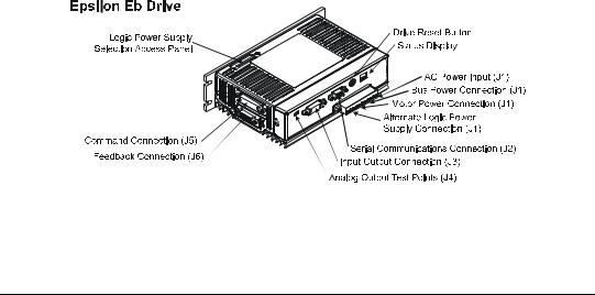
Figure 1: Epsilon Eb Drives Feature Location
2
Installation
Basic Installation Notes
You are required to follow all safety precautions during startup such as providing proper equipment grounding, correctly fused power, and an effective Emergency Stop circuit which can immediately remove power in the case of a malfunction. See the “Safety Considerations” section for more information.
Electromagnetic Compatibility (EMC)
Drives are designed to meet the requirements of EMC. Under extreme conditions a drive might cause or suffer from disturbances due to electromagnetic interaction with other equipment. It is the responsibility of the installer to ensure that the equipment or system into which the drive is incorporated complies with the relevant EMC legislation in the country of use.
The following instructions provide you with installation guidance designed to help you meet the requirements of the EMC Directive 89/336/EEC.
Adhering to the following guidelines will greatly improve the electromagnetic compatibility of your system; however, final responsibility for EMC compliance rests with the machine builder, and Control Techniques cannot guarantee your system will meet tested emission or immunity requirements.
If you need to meet EMC compliance requirements, EMI/RFI line filters must be used to control conducted and radiated emissions as well as improve conducted immunity.
Physical location of these filters is very important in achieving these benefits. The filter output wires should be kept as short as possible (12 inches is suggested) and routed away from the filter input wires. In addition:
•Choose an enclosure made of a conductive material such as steel, aluminum, or stainless steel.
•Devices mounted to the enclosure mounting plate, which depend on their mounting surfaces for grounding, must have the paint removed from their mounting surfaces and the mating area on the mounting plate to ensure a good ground. See “Achieving Low Impedance Connections” on page 4 for more information.
•If grounding is required for cable grommets, connectors, and/or conduit fittings at locations where cables are mounted through the enclosure wall, paint must be removed from the enclosure surface at the contact points.
•AC line filter input and output wires and cables should be shielded, and all shields must be grounded to the enclosure.
3

Epsilon Eb Digital Servo Drive Installation Manual
Achieving Low Impedance Connections
Noise immunity can be improved and emissions reduced by making sure that all the components have a low impedance connection to the same ground point. A low impedance connection is one that conducts high frequency current with very little resistance. Impedance cannot be accurately measured with a standard ohmmeter, because an ohmmeter measures DC resistance. For example, a 12-inch-long, 8-gauge,round wire has a significatly higher impedance than a 12-inch-long, 12-gauge, flat braided conductor. A short wire has less impedance than a larger one.
Low impedance connections can be achieved by bringing large areas of conductive surfaces into direct contact with each other. In most cases this requires paint removal because a ground connection through bolt threads is not sufficient. However, component materials should be conductive, compatible, and exhibit good atmospheric corrosion resistance to prevent loss through corrosion, which will hinder the low impedance connection. Enclosure manufacturers offer corrosion resistant, unpainted mounting plates to help.
Bringing components into direct contact cannot always be achieved. In these situations a conductor must be relied upon to provide a low impedance path between components. Remember a flat braided wire has lower impedance than a round wire of a large guage rating.
A low impedance connection should exist among the following components:
•Enclosure and mounting plate
•Servo amplifier chassis and mounting plate
•EMI/RFI AC line filter chassis and mounting plate
•Other interface equipment chassis and mounting plate
•Other interface equipment chassis and electrical connectors
•Enclosure and conduit fittings or electrical connectors
•Enclosure mounting plate and earth ground
•Motor frame and conduit fittings or electrical connectors
•Encoder chassis and electrical connector
A good rule to follow when specifying conductors for high frequency applications is to use a metal strap with a length to width ratio that is less than 3:1.
4

Installation
AC Line Filters
The AC line filters used during Control Techniques’ compliance testing are listed below. These filters are capable of supplying the drive input power to the specified drive under maximum output power conditions.
Epsilon |
E Series |
Schaffner Part # |
Control Techniques Part # |
Rating |
|
Eb-202, Eb-203 |
|
FN2070-10/08 |
960307-01 |
10A, 240V, 1 Ø |
|
|
|
|
|
||
EN-204 |
FS5278-16/08 |
960305-01 |
16A, 240V, 1 Ø |
||
|
|||||
|
|
|
|
||
Eb-205 |
EN-208 |
FS5278-16/08 |
960305-01 |
||
|
|||||
|
|
|
|
|
|
|
EN-214 |
FN-258/16 |
960304-01 |
16A, 480V, 3 Ø |
|
|
|
|
|
|
Alternately, Control Techniques has also seen good results with the following line filters:
Drive |
Part # |
Rating |
EN-204 |
|
|
|
Corcom 20EQ1 |
|
EN-208 |
20A, 240V, 1 Ø |
|
|
|
|
Eb-202, Eb-203, Eb-205 |
|
|
|
|
|
Eb-202 |
Schaffner FN 2070-6-06 |
6A, 240V, 1 Ø |
|
|
|
AC Line Filter Installation Notes
•EMC criteria can be met in installations where multiple drives are supplied through a single filter, however, it is the installers responsibility to verify EMC compliance. Questions on this subject should be directed to the filter manufacturer.
•It is critical that you keep the filter inputs routed away from any electrical noise sources to prevent noise from being induced into them and carried out of the enclosure.
5
Epsilon Eb Digital Servo Drive Installation Manual
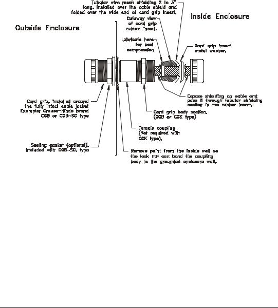
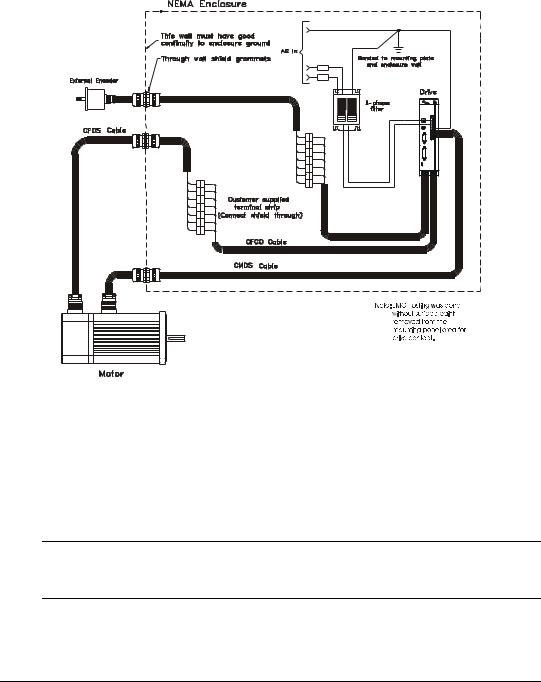
Cable to Enclosure Shielding
Shielded motor, feedback, serial communications, and external encoder cables were used for Control Technicques’ compliance testing and are necessary to meet the EMC requirements. Each cable shield was grounded at the enclosure wall by the type of grommet described earlier and shown in the figure below.
|
|
|
|
|
|
|
|
|
|
|
|
|
|
|
|
|
|
|
|
|
|
|
|
|
|
|
|
|
|
|
|
|
|
|
|
|
|
|
|
|
|
|
|
|
|
|
|
|
|
|
|
|
|
|
|
|
|
|
|
|
|
|
|
|
|
|
|
|
|
|
|
|
|
|
|
|
|
|
|
|
|
|
|
|
|
|
|
|
|
|
|
|
|
|
|
|
|
|
|
|
|
|
|
|
|
|
|
Figure 2: |
Through Wall Shield Grommet |
|
|
|
|
|
|||||
|
|
|
|
|
|
|
|
|
|
|
|
Cable Type |
Control Techniques |
Shielded Cable |
|
Conduit Dimension |
Actual Hole Size |
||||||
Cable Model |
Grommet Kit Part # |
|
Hole Size |
||||||||
|
|
|
|
||||||||
Motor Cable, 16 Ga |
|
CMDS |
CGS-050 |
|
1/2" pipe |
7/8" |
|||||
|
|
|
|
|
|
|
|
|
|
|
|
Motor Cable, 12 Ga |
|
CMMS |
CGS-050 |
|
1/2" pipe |
7/8" |
|||||
|
|
|
|
|
|
|
|
|
|
|
|
Feedback Cable |
|
CFOS |
CGS-050 |
|
1/2" pipe |
7/8" |
|||||
|
|
|
|
|
|
|
|
|
|
|
|
Flex Motor Cable, 16 Ga |
|
CMDF |
CGS-050 |
|
1/2" pipe |
7/8" |
|||||
|
|
|
|
|
|
|
|
|
|
|
|
Flex Motor Cable, 12 Ga |
|
CMMF |
CGS-075 |
|
3/4" pipe |
1 1/16" |
|||||
|
|
|
|
|
|
|
|
|
|
|
|
Flex Feedback Cable |
CFCF, CFOF |
CGS-063 |
|
3/4" pipe |
1 1/16" |
||||||
|
|
|
|
|
|
|
|
|
|
|
|
External Encoder |
|
ENCO |
CGS-038 |
|
1/2" pipe |
7/8" |
|||||
|
|
|
|
|
|
|
|
|
|
|
|
AC Power |
user supplied |
user supplied |
|
|
|
|
|
||||
|
|
|
|
|
|
|
|
|
|
|
|
6
Installation
Figure 3: AC Filter and Cable Connections for Epsilon Drives
Environmental Considerations
If the product will be subjected to atmospheric contaminants such as moisture, oils, conductive dust, chemical contaminants, and metallic particles, you must mount it vertically in a metal NEMA type 12 enclosure.
If the ambient temperature inside the enclosure will exceed 40° C (104° F), you must consider forced air cooling.
Note
For Epsilon drives, surrounding air ambient temperature can be up to 50°C (122° F) with 3% linear derating for every degree above 40° C (104° F)
The amount of cooling depends on the size of the enclosure, the thermal transfer of the enclosure to the ambient air, and the amount of power being dissipated inside the enclosure. Consult your enclosure manufacturer for assistance with determining cooling requirements.
7

Epsilon Eb Digital Servo Drive Installation Manual
Wiring Notes
•To avoid problems associated with EMI (electromagnetic interference), you should route high power lines (AC input power and motor power) away from low power lines (encoder feedback, serial communications, etc.).
•If a neutral wire (not the same as Earth Ground), is supplied from the building distribution panel it should never be bonded with PE wire in the enclosure.
•You should consider future troubleshooting and repair when installing all wiring. All wiring should be either color coded and/or tagged with industrial wire tabs.
•As a general rule, the minimum cable bend radius is ten times the cable outer diameter.
•All wiring and cables, stationary and moving, must be protected from abrasion.
•Ground wires should not be shared with other equipment.
•Ensure that metal to metal contact is made between the enclosure ground lug and the metal enclosure, not simply through the mounting bolt and threads.
•All inductive coils must be suppressed with appropriate devices, such as diodes or resistor/capacitor (RC) networks.
Mechanical Installation
Drive Mounting
Drives must be back mounted vertically on a metal surface such as a NEMA enclosure. A minimum spacing of two inches must be maintained above and below the drive for ventilation. Side by side drive spacing requirements vary by drive size and RMS loading. Additional space may be necessary for wiring and cable connections.
For drive dimensions, weights and mounting specifications, see the "Specifications" section.
Motor Mounting
Motors should be mounted firmly to a metal mounting surface to ensure maximum heat transfer for maximum power output and to provide a good ground.
For motor dimensions, weights and mounting specifications, see the “Specifications” chapter.
8

Installation
Electrical Installation
Figure 4: Typical System Grounding Diagram
9
Epsilon Eb Digital Servo Drive Installation Manual
Power Supply Requirements
The examples below show AC power connections for single phase and three phase drives. These examples are shown for reference only. Local electrical codes should be consulted before installation.
The Protective Earth (PE) wire connection is mandatory for human safety and proper operation. This connection must not be fused or interrupted by any means. Failure to follow proper PE wiring can cause death or serious injury.
Epsilon Only
The Eb-202, Eb-203 and Eb-205 drives require 42 to 264 VAC single-phase power. An Epsilon drive can be connected to any pair of power phases on a 1 Ø or 3 Ø power source that is grounded as shown in the following diagrams.
Epsilon Only
If using an APS Logic Power input and the Low DC Bus fault is disabled, minimum supply voltage to an Epsilon can be reduced to 15 VAC on the AC inputs or 24 VDC on the Bus +/- connections.
Note
The maximum voltage applied to the drive terminals must not exceed 264 VAC phase to phase and phase to PE ground. This can be accomplished by referencing the AC supply to earth ground.
Do not connect or disconnect the AC power by inserting or removing the AC power connector. Using the connector in this manner, even once, will damage the connector, making it unusable.
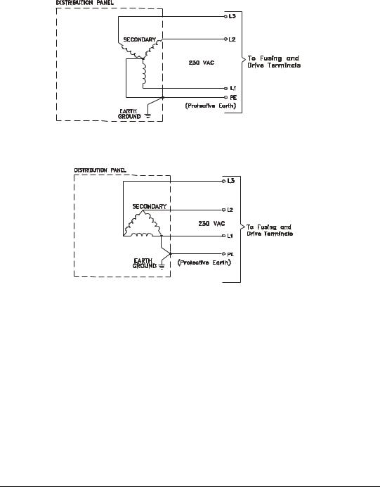
AC Supplies NOT Requiring Transformers
If the distribution transformer is configured as shown in the figures below, the AC power supply can be connected directly to the amplifier terminals.
10
Installation
Figure 5: Earth Grounded WYE Distribution Transformer
Figure 6: Earth Grounded Delta Distribution Transformer
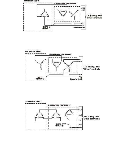
AC Supplies Requiring Transformers
If the distribution transformer is configured as shown in the figures below, an isolation transformer is required.
If an isolation transformer is used between the power distribution point and the drives, the transformer secondary must be grounded for safety reasons as shown in the figures below.
11
Epsilon Eb Digital Servo Drive Installation Manual
Figure 7: Three Phase Delta (with mid-phase GND) Distribution to a Three-Phase Delta/WYE Isolation Transformer
Figure 8: Three Phase WYE (ungrounded) Distribution to a Three-Phase Delta/WYE Isolation Transformer
Figure 9: Delta to Delta Isolation Transformer
12
 Loading...