

Page 1
MHM-97125-PBF-EN, Rev 0
AMS 6500 Machinery Health Monitor
A6560R Processor Module and A6510 Signal Input Module
Reference Manual
May 2017
Page 2

Copyright
©
2017 by Emerson. All rights reserved.
No part of this publication may be reproduced, transmitted, transcribed, stored in a retrieval system, or translated into any
language in any form by any means without the written permission of Emerson.
Disclaimer
This manual is provided for informational purposes. EMERSON MAKES NO WARRANTY OF ANY KIND WITH REGARD TO THIS
MATERIAL, INCLUDING, BUT NOT LIMITED TO, THE IMPLIED WARRANTIES OF MERCHANTABILITY AND FITNESS FOR A PARTICULAR
PURPOSE. Emerson shall not be liable for errors, omissions, or inconsistencies that may be contained herein or for incidental or
consequential damages in connection with the furnishing, performance, or use of this material. Information in this document is
subject to change without notice and does not represent a commitment on the part of Emerson. The information in this manual is
not all-inclusive and cannot cover all unique situations.
Trademarks and Servicemarks
See http://www2.emersonprocess.com/siteadmincenter/PM Central Web Documents/marks.pdf
All other marks are property of their respective owners.
Patents
The product(s) described in this manual are covered under existing and pending patents.
Page 3

Contents
Contents
Chapter 1 Introduction ...................................................................................................................1
1.1 About this manual ........................................................................................................................1
1.2 Documentation conventions .......................................................................................................1
1.3 Technical Support and Customer Service ..................................................................................... 2
1.5 China RoHS Compliance ...............................................................................................................3
Chapter 2 Product Introduction ......................................................................................................5
2.1 AMS 6500 front view ....................................................................................................................6
2.2 System walkthrough .................................................................................................................... 7
2.3 System documentation ................................................................................................................7
Chapter 3 Sensor installation ........................................................................................................13
Chapter 4 Enclosure mounting ..................................................................................................... 15
4.1 Junction boxes ........................................................................................................................... 15
4.2 Wall mount enclosures .............................................................................................................. 18
4.3 AMS 6500 rack chassis ............................................................................................................... 19
Chapter 5 Cabling requirements ...................................................................................................25
5.1 Guidelines for conduit installation ..............................................................................................25
5.2 Online instrumentation cable .....................................................................................................26
5.3 Pull cable from the junction box to the unit ................................................................................27
5.4 Physical network segment for the unit ....................................................................................... 28
5.5 Power circuit guidelines for the unit enclosure ...........................................................................28
5.6 Recommendations for improving signal quality ......................................................................... 30
Chapter 6 Wire terminations ........................................................................................................33
6.1 Terminate instrumentation wiring ............................................................................................. 33
6.2 Terminate bundled cable ........................................................................................................... 36
6.3 Wire termination at the AMS 6500 .............................................................................................37
6.4 Signal routing from the monitoring panel to the prediction panel ..............................................43
6.5 Terminate discrete I/O ............................................................................................................... 44
6.6 Rear shield/Adapter panel—A6500-M-RSH .................................................................................46
6.7 Terminate +24 V power for the A6560 and A6510 modules ....................................................... 46
6.8 Eddy Current sensor: -24 V power supply ................................................................................... 47
6.9 SysFail relay termination ............................................................................................................ 48
6.10 Loop interconnection for 4-20 mA current ................................................................................. 48
6.11 Terminate Ethernet connection ................................................................................................. 49
6.12 Default schema for network addressing .....................................................................................50
Chapter 7 Hardware configuration ...............................................................................................53
7.1 Hardware configuration: overview ............................................................................................. 53
7.2 The A6560R and A6510 modules ............................................................................................... 54
7.3 Configure the A6560R with a terminal emulator ........................................................................ 62
Chapter 8 Software configuration ................................................................................................ 67
8.1 System overview diagram .......................................................................................................... 67
8.2 System configuration overview ..................................................................................................68
8.3 Install AMS Machinery Manager ................................................................................................. 69
MHM-97125-PBF-EN, R0 i
Page 4

Contents
8.4 Configure the FTP server to download firmware .........................................................................69
8.5 Connect the A6560R CPU to AMS Machinery Manager ...............................................................73
Chapter 9 Data collection and analysis ..........................................................................................75
9.1 Online database diagram .......................................................................................................... 75
9.2 View or edit IP addresses with the unit ....................................................................................... 77
9.3 Verify or assign a unit IP address to the Online Server in RBM Network Administration ...............78
9.4 Add a unit's IP address to the Online Server in RBM Network Administration .............................. 79
9.5 Online database configuration: overview ................................................................................... 79
9.6 Online Watch overview .............................................................................................................. 83
9.7 Archive management ................................................................................................................ 86
9.8 Create an archive manually ........................................................................................................ 87
9.9 Disable archive predicates ..........................................................................................................87
9.10 Stop transient acquisition .......................................................................................................... 88
9.11 Remove an archive from the Transient Archive Status tab ..........................................................88
9.12 Change databases when moving the AMS 2600 to a new machine .............................................89
Chapter 10 Specifications ...............................................................................................................91
10.1 AMS 6500 Machinery Health™ Monitor specifications ................................................................ 91
10.2 Environmental specifications ..................................................................................................... 92
10.3 A6560R Processor module LEDs .................................................................................................92
10.4 A6510 Signal Input module LEDs ............................................................................................... 95
Chapter 11 System calibration ....................................................................................................... 97
11.1 System calibration overview ...................................................................................................... 97
Chapter 12 Data types ..................................................................................................................101
12.1 Gross Scan analysis .................................................................................................................. 101
12.2 Spectral analysis .......................................................................................................................102
12.3 Time Waveform analysis .......................................................................................................... 103
12.4 Non-Vibration unit analysis types .............................................................................................104
12.5 Set DC offset ............................................................................................................................104
Index ................................................................................................................................................107
ii MHM-97125-PBF-EN, R0
Page 5

1 Introduction
Topics covered in this chapter:
• About this manual
• Documentation conventions
• Technical Support and Customer Service
• Disclaimer
• China RoHS Compliance
1.1 About this manual
This document covers the standard system components of the prediction system. For
some installations, non-standard components may be purchased with the online system;
for each of these components, Emerson will include an installation guide supplement. If
the product component cannot be found in the installation guide, please contact your
project manager to request an installation guide supplement.
Introduction
Other available manuals detail protection capabilities.
WARNING!
All wiring should be installed by a qualified electrician. Wiring must conform to all applicable
local codes and regulations. Local codes and regulations regarding wire type, wire size, color
codes, insulation voltage ratings, and any other standards must be followed.
1.2 Documentation conventions
The following conventions are used throughout:
Note
A note paragraph contains special comments or instructions.
CAUTION!
A caution paragraph alerts you to actions that can have a major impact on the equipment or
stored data.
WARNING!
A warning paragraph alerts you to actions that can have extremely serious consequences for
equipment and/or personnel.
MHM-97125-PBF-EN, R0 1
Page 6

Introduction
1.3 Technical Support and Customer Service
When you contact Technical Support, be ready with a screen capture of the error message
and details such as when and how the error occurred.
Hardware Technical Help
Have the number of the current version of your firmware ready when you call.
Software Technical Help
Provide the software version numbers of both your Microsoft® Windows operating system
and AMS Machinery Manager, and your AMS Machinery Manager serial number. To find
AMS Machinery Manager version and serial numbers, select Help > About.
Be at your computer when you call. We can serve you better when we can work through
the problem together.
Software Technical Support
Emerson provides technical support through the following for those with an active support
agreement:
• Telephone assistance and communication via the Internet.
• Mass updates that are released during that time.
• Interim updates upon request. Please contact Emerson Technical Support for more
information.
Customer Service
Contact Customer Service for all non-technical issues, such as ordering replacement parts.
Contact us
For Emerson Technical Support and Customer Service Toll Free numbers, email addresses,
and hours of operation, please visit
http://www2.emersonprocess.com/en-US/brands/sureservice/Pages/TechnicalSupport.aspx
1.4 Disclaimer
This manual is provided for informational purposes. EMERSON MAKES NO WARRANTY OF
ANY KIND WITH REGARD TO THIS MATERIAL, INCLUDING, BUT NOT LIMITED TO, THE
IMPLIED WARRANTIES OF MERCHANTABILITY AND FITNESS FOR A PARTICULAR PURPOSE.
Emerson shall not be liable for errors, omissions, or inconsistencies that may be contained
herein or for incidental or consequential damages in connection with the furnishing,
performance, or use of this material. Information in this document is subject to change
without notice and does not represent a commitment on the part of Emerson. The
information in this manual is not all-inclusive and cannot cover all unique situations.
2 MHM-97125-PBF-EN, R0
Page 7

1.5 China RoHS Compliance
Our products manufactured later than June 30, 2016 and which are sold in the People's
Republic of China are marked with one of the following two logos to indicate the
Environmental Friendly Use Period in which it can be used safely under normal operating
conditions.
Products without below mentioned marking are either manufactured before June 30 or are
non Electrical Equipment Products (EEP).
Circling arrow symbol with "e": The product contains no hazardous substances over
the Maximum Concentration Value and it has an indefinite Environmental Friendly
Use Period.
Circling arrow symbol with a number: This product contains certain hazardous
substances over the Maximum Concentration Value and it can be used safely under
normal operating conditions for the number of years indicated in the symbol. The
names and contents of hazardous substances can be found in folder "China RoHS
Compliance Certificates" on the documentation CD or DVD enclosed with the
product.
Introduction
MHM-97125-PBF-EN, R0 3
Page 8

Introduction
4 MHM-97125-PBF-EN, R0
Page 9

2 Product Introduction
Topics covered in this chapter:
• AMS 6500 front view
• System walkthrough
• System documentation
Product Introduction
MHM-97125-PBF-EN, R0 5
Page 10
Product Introduction
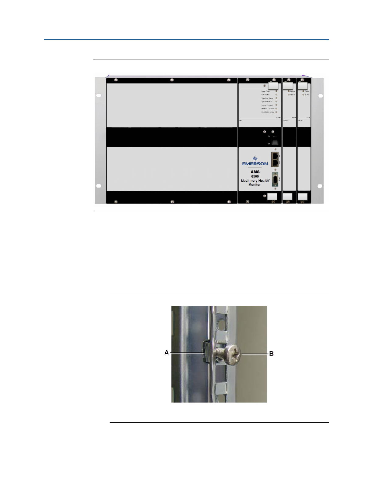
2.1 AMS 6500 front view
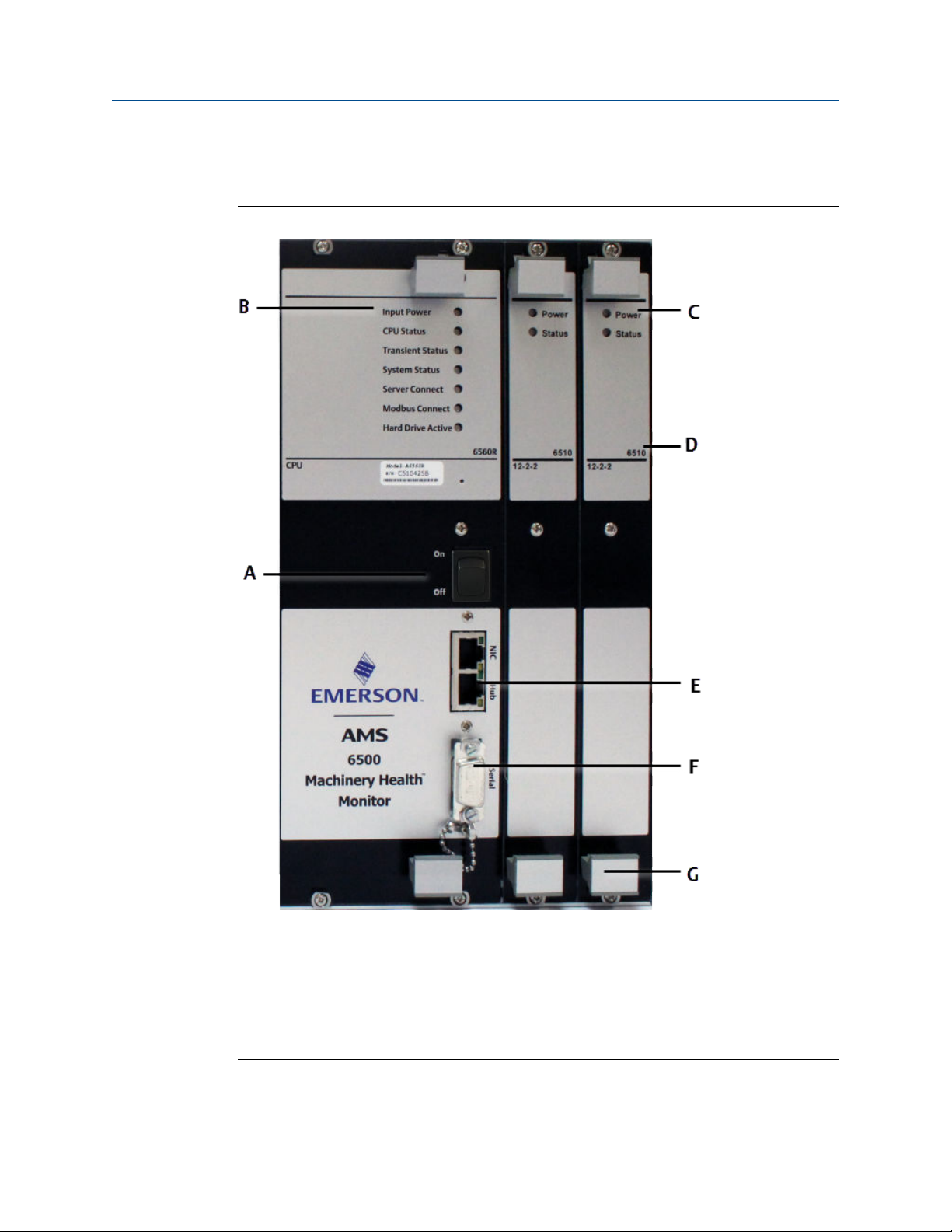
AMS 6500 front view with A6560R and A6510 modulesFigure 2-1:
A. Front power switch
B. A6560R Status LEDs
C. A6510 Status LEDs
D. Module name
E. 2 Ethernet ports — NIC and Hub
F. Serial port
G. Handles
6 MHM-97125-PBF-EN, R0
Page 11

2.2 System walkthrough
Perform a system component review to ensure that the proper system components have
been shipped, and that nothing has been lost or damaged during shipment. Unpack and
inspect to confirm all system components are present. After installation, physically walk
through each part of the installation to review:
Sensor mounting locations
□
Cable pulls
□
Conduit/cable tray use
□
Enclosure mounting locations
□
Environmental concerns
□
2.3 System documentation
Typical system documentation includes at least a System Overview Drawing, System
Layout Drawings, a Cable Administration Chart.
Product Introduction
2.3.1 System overview drawings
AMS 6500 system documentation should include system overview drawings that illustrate
how system components interconnect. Create system overview drawings for your system
and update them as you make any changes to your system.
MHM-97125-PBF-EN, R0 7
Page 12
Product Introduction
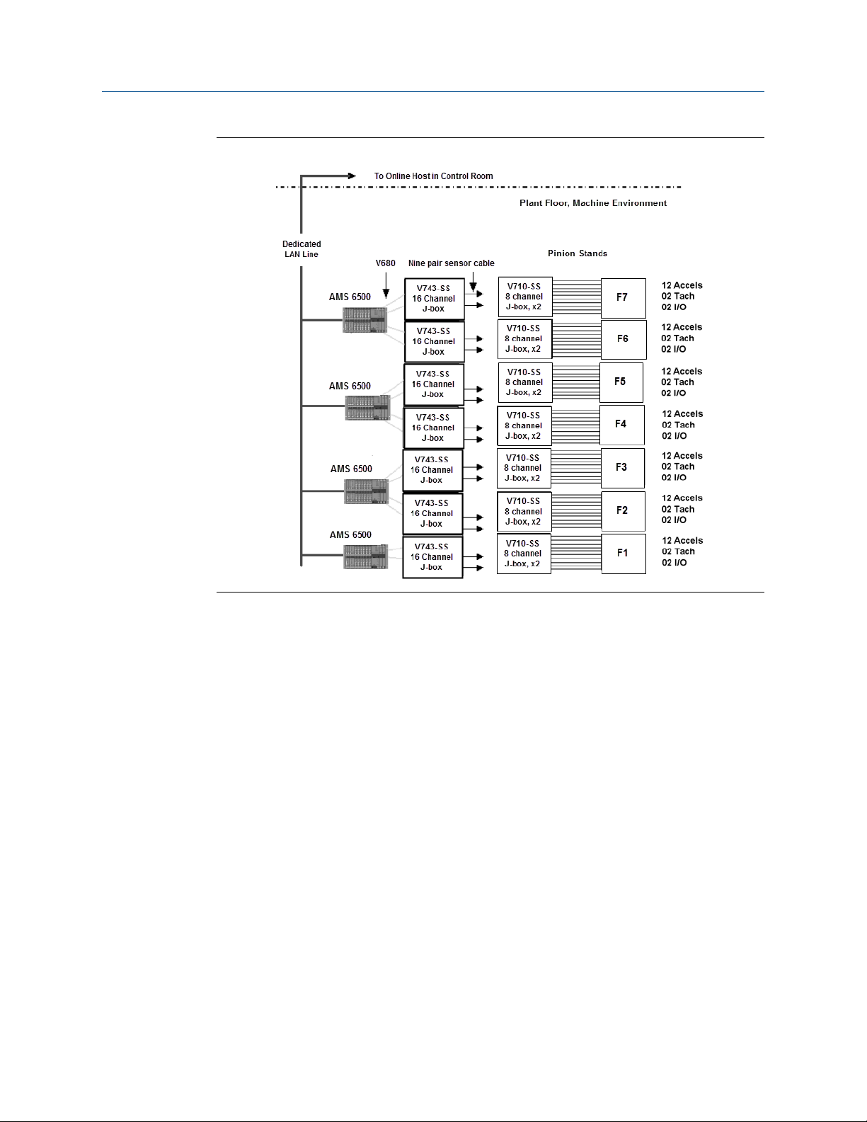
Example system overview drawingFigure 2-2:
A system overview drawing typically includes the following information:
• AMS 6500 units
• Junction/switch boxes
• Cables
• AMS 6500 Network Segment Cables
• Tags for each AMS 6500, junction/switch box, and cable
2.3.2 System layout drawings
The system layout drawings illustrate exact locations for enclosure mounting, conduit
installation, cable pulls, and sensor mounting. The most common method for preparing
these drawings is to copy blueprints of the plant floor/production line and mark the system
installation locations. Use color-coded highlights and symbols to mark the different types
of cable runs and enclosure mountings.
8 MHM-97125-PBF-EN, R0
Page 13
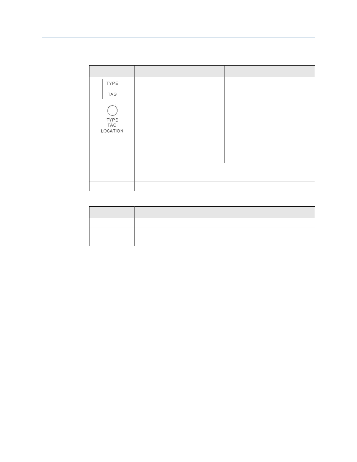
Example system layout marking guidelinesTable 2-1:
Symbol Description Labels
Enclosure Type: 701 (2,3), 745, 6500
Tag: defined by plant
Instrumentation Type: sensor part #
Tag: defined by plant
Location:
• I—Inboard
• O—Outboard
• A—Axial
• H—Horizontal
• V—Vertical
——————— Exposed cable
– – – – – – – – Cable in conduit
— - — - — - — Cable tray
Example system layout marking guidelinesTable 2-1:
Product Introduction
Color codes Cable type
Red Instrumentation
Blue Multi-pair bundled cable
Green AMS 6500 network cabling
2.3.3 Cable administration charts
Cable administration charts document wire terminations within system enclosures. Tag
names should be consistent and represent physical locations or machines. For instance,
instead of naming a sensor 23001, use a name like FAN1OV (fan number 1 outboard
vertical) to make system maintenance and troubleshooting easier. After tags are assigned,
document them in cable administration charts. All enclosures for the system need cable
administration charts.
There are two types of cable administration charts for the online system: junction box and
AMS 6500 enclosure.
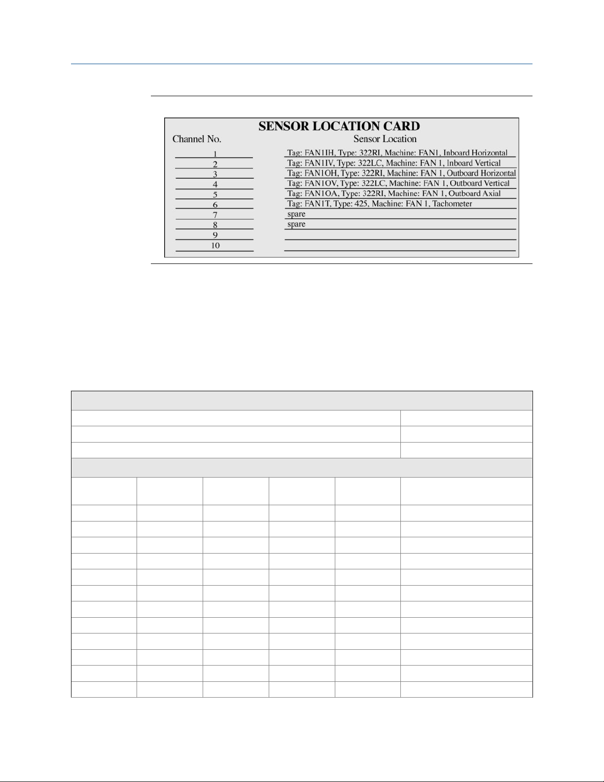
Junction box cable administration chart
The online system junction boxes provide a junction between the instrumentation cable
and the multi-pair bundled cable that is pulled back to the AMS 6500. The cable
administration chart for a junction box documents the channel number, wire tag, sensor
type, and sensor location if the wire tag does not contain location information. Figure 2-3
shows a typical installation.
MHM-97125-PBF-EN, R0 9
Page 14
Product Introduction
Junction box cable administration chartFigure 2-3:
AMS 6500 enclosure cable administration chart
The AMS 6500 has cable terminations for sensors, tachometers, discrete I/O, network, and
power; it also has configurable DIP switches and jumpers.
The cable terminations and DIP switch settings should be documented in cable
administration charts or CAD drawings.
Example AMS 6500 cable administration chartTable 2-2:
Processor module
AMS 6500 tag name:
A6560R CPU module MAC address:
Network cable tag:
MSIG #1 sensor inputs
Channel # Junction box
tag
1
2
3
4
5
6
7
8
9
10
11
12
Wire tag Sensor type DIP setting Sensor location
10 MHM-97125-PBF-EN, R0
Page 15

Example AMS 6500 cable administration chart (continued)Table 2-2:
1
2
1
2
MSIG #2 sensor inputs
Channel # Junction box
tag
1
2
3
4
5
6
7
8
9
10
11
12
1
2
1
2
Product Introduction
Tachometer inputs
Discrete I/O
Wire tag Sensor type DIP setting Sensor location
Tachometer inputs
Discrete I/O
2.3.4 Documentation storage
Make copies of system overview drawings, system layout drawings, and mechanical and
electrical drawings. Keep them in the system enclosure to allow easy reference by analysts
and service personnel.
MHM-97125-PBF-EN, R0 11
Page 16

Product Introduction
12 MHM-97125-PBF-EN, R0
Page 17

3 Sensor installation
Ensure sensors are installed according to instructions provided by the sensor manufacturer
and industry best practices.
Sensor installation
MHM-97125-PBF-EN, R0 13
Page 18

Sensor installation
14 MHM-97125-PBF-EN, R0
Page 19

4 Enclosure mounting
Topics covered in this chapter:
• Junction boxes
• Wall mount enclosures
• AMS 6500 rack chassis
4.1 Junction boxes
Junction boxes are used to terminate online instrumentation wiring. Emerson
recommends junction boxes with 12 channels, housed in a fiberglass or stainless steel
enclosure. They should consist of individual, 3-lug terminal blocks mounted on a DIN rail.
4.1.1 Mount junction boxes
Enclosure mounting
1. Ensure the chosen mounting location is well lit and allows proper clearance for
maintenance access.
MHM-97125-PBF-EN, R0 15
Page 20
Enclosure mounting
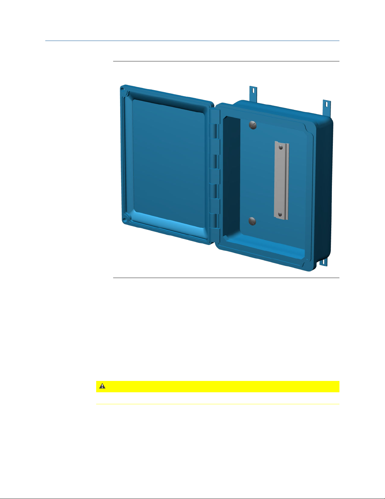
Junction box access requirementsFigure 4-1:
Junction boxes require a 180° opening.
2. Prepare the mounting bracket using the outline drawing as a template for the
mounting hole locations.
3. Use the machine screws to attach the mounting feet to the back of the enclosure.
Align mounting feet vertically to ensure proper access.
Torque screws to 31 in-lb.
4. Using bolts provided by the contractor, attach the enclosure to the mounting
bracket.
4.1.2 Junction box wiring notes
CAUTION!
Never cross-connect shields from different sensors in junction boxes.
16 MHM-97125-PBF-EN, R0
Page 21
Enclosure mounting
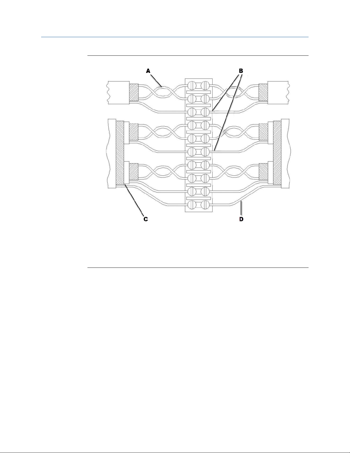
Junction box wiring notesFigure 4-2:
A. Maintain cable pair twists as close to the terminal block as possible.
B. Do not allow shield drain wires or foil from individual cables to short. Use heat shrink and dress
wire ends as necessary.
C. Strip the insulation and shield as close to the terminal block as possible.
D. Connect multiple-pair shield drain wire individually. Do not allow shield drain wires or foil from
individual cables to short. Use heat shrink and dress wire ends as necessary.
MHM-97125-PBF-EN, R0 17
Page 22

Enclosure mounting
Modifications for junction box wiringFigure 4-3:
A. Connecting the shield line to the sensor "-" conductor at the sensor end may reduce RF and static
interference. You must isolate sensor shield and "-" conductors from earth ground or the shield
connection at the 6500 side may cause ground loops.
B. Connecting a multi-pair cable overall shield to earth ground at both ends may reduce RF and static
interference. This connection may cause ground loops.
4.2 Wall mount enclosures
The prediction racks are designed to easily mount inside a standard size enclosure.
Emerson offers pre-wired wall mount enclosures for AMS 6500 prediction systems:
Wall mount cabinet System Channels Dimensions Rack size
A6500MS-24-ENCL-IC A6500MS 12 or 24 24”H x 16”W x 12”D 7.5 inch
A6500PRE-SS-WM-24-IC A6500MR 12 or 24 36”H x 24”W x 12”D 19 inch
A6500PRE-SS-WM-48-IC A6500MR 36 or 48 36”H x 24”W x 12”D 19 inch
Note
Install cabinets using guidelines provided by Emerson projects.
• Install at a reasonable height for easy access.
• All cable and conduit piercing should be through the bottom of the cabinet. See Chapter 5.
18 MHM-97125-PBF-EN, R0
Page 23
Enclosure mounting
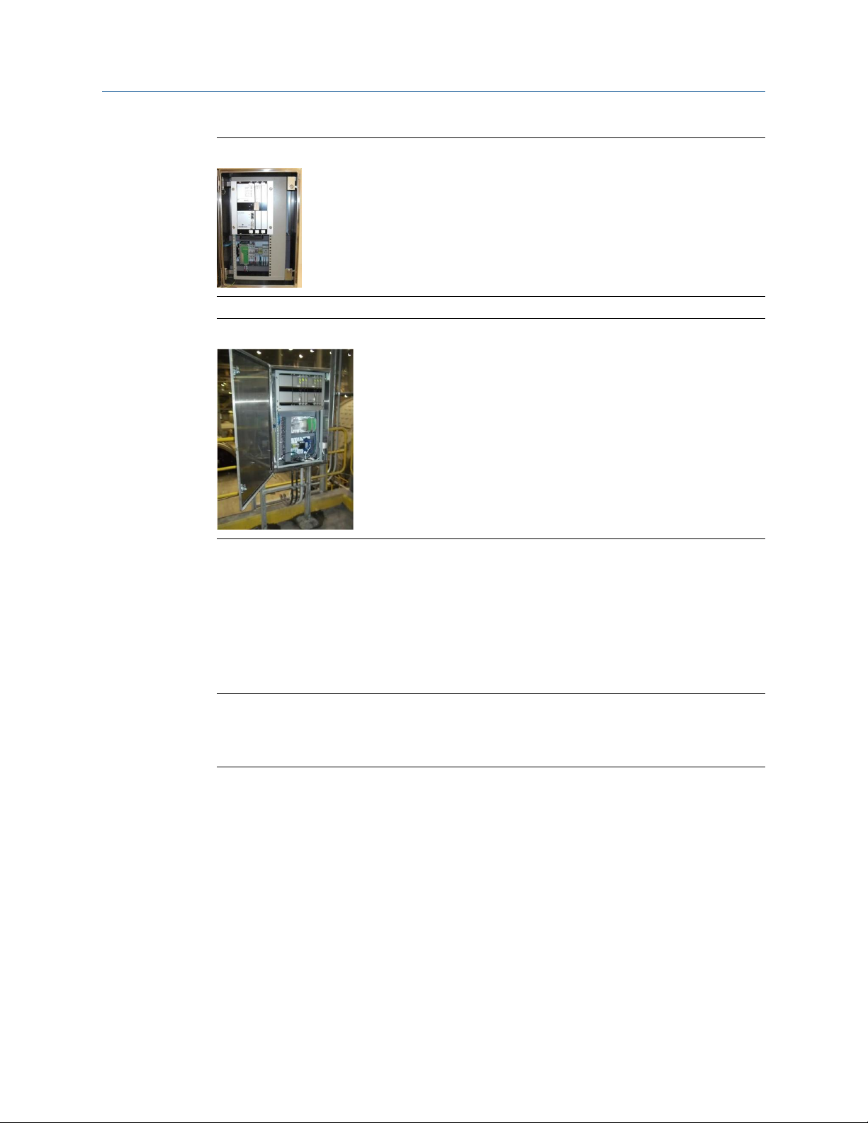
A6500MS in a compact wall-mount enclosureFigure 4-4:
A6500MR in a full wall-mount enclosure (48 channels shown)Figure 4-5:
4.3 AMS 6500 rack chassis
To protect it from harsh industrial environments, the AMS 6500 rack chassis is either
mounted on 19 in. rack mounting rails in a cabinet enclosure with rear termination panels,
or in a stainless steel housing with a front termination panel.
Note
All AMS 6500 enclosures must be grounded to earth. Ground the enclosure through conduit or
mounting structure if it is grounded to earth. Otherwise, use a bonding wire to connect the
enclosure to earth ground.
4.3.1 Mount the rack chassis in a 19 in. cabinet enclosure
The AMS 6500 is generally installed in a cabinet enclosure with 19 in. rack mounting rails.
Mounting hardware includes four each of cage nuts, finishing washers, and screws.
MHM-97125-PBF-EN, R0 19
Page 24
Enclosure mounting
AMS 6500 for mounting in a 19 in. cabinet enclosureFigure 4-6:
Prerequisites
You need two people to lift the unit and place it on the mounting rails.
Procedure
1. Attach the cage nuts in the mounting rails.
2. Using the screws and finishing washers, fasten the system frame to the mounting
rails through the two oblong holes on each side of the frame.
Cage nuts and screws in the mounting railsFigure 4-7:
A. Cage nut
B. Screw
20 MHM-97125-PBF-EN, R0
Page 25

Enclosure mounting
3. When mounting multiple units in one cabinet, place a cooling fan rack between
each unit to maintain the specified environmental operating conditions for all
components.
4.3.2 Mount the rack chassis in a stainless steel enclosure
Prerequisites
If you are not running conduit into a stainless steel enclosure, confirm that the mounting
location provides a path to earth ground.
Procedure
1. Ensure the mounting location allows the door to open completely and allows
enough room to run conduit into the bottom of the box.
2. Using hardened steel bolts, attach all four mounting feet to unistrut rails.
3. Torque lock washers to 50 ft-lb.
4.3.3 Cable access
As a best practice, conduit should enter from the bottom of the enclosure. Power, sensor,
and communication cables should enter through separate conduit and be routed
separately inside the enclosure.
Prepare multi-pair bundled cable pulls
1. Determine the number of pulls you need based on the size and number of channels
supported by the junction box. In general, you need one pull per 6 channels. Do not
exceed 40% conduit fill.
The multi-pair cable normally has a diameter of 0.5 in., and will require a 1.5 in.
conduit run. Two multi-pair cable pulls will require a 2 in. conduit run.
2. Make multi-pair sensor cable pulls on the bottom left so you can easily route cables
along left side of enclosure.
Prepare power cables
1. Size the conduit according to plant codes and local regulations for running power in
the plant.
2. Make the power line pull to the bottom right rear of the enclosure to route power
cable along the right rear of the enclosure.
Prepare Ethernet cables
1. The CAT5 cable requires a minimum 0.5 in. conduit run.
2. Route the CAT5 cable along the bottom right front so that it is as far as possible from
the unit's power supply.
MHM-97125-PBF-EN, R0 21
Page 26
Enclosure mounting
Prepare discrete input/output cables
AMS 6500 discrete input/output cable pulls are low voltage DC only, so they can be routed
with sensor cables or routed separately. They consist of either multi-pair bundled cable
pulls or single twisted pair cable.
Procedure
1. For multi-pair bundled cable pulls, prepare 1.5 in. conduit for one cable and 0.5 in.
extra for each additional cable.
2. Run single twisted-pair cable in conduit or pull through the enclosure using 0.25 in.
cord grips.
4.3.4 Install and remove modules
The AMS 6500 system cabinet can be configured to contain both prediction and
protection modules. In Figure 4-8, the protection modules (3U high modules) are shown on
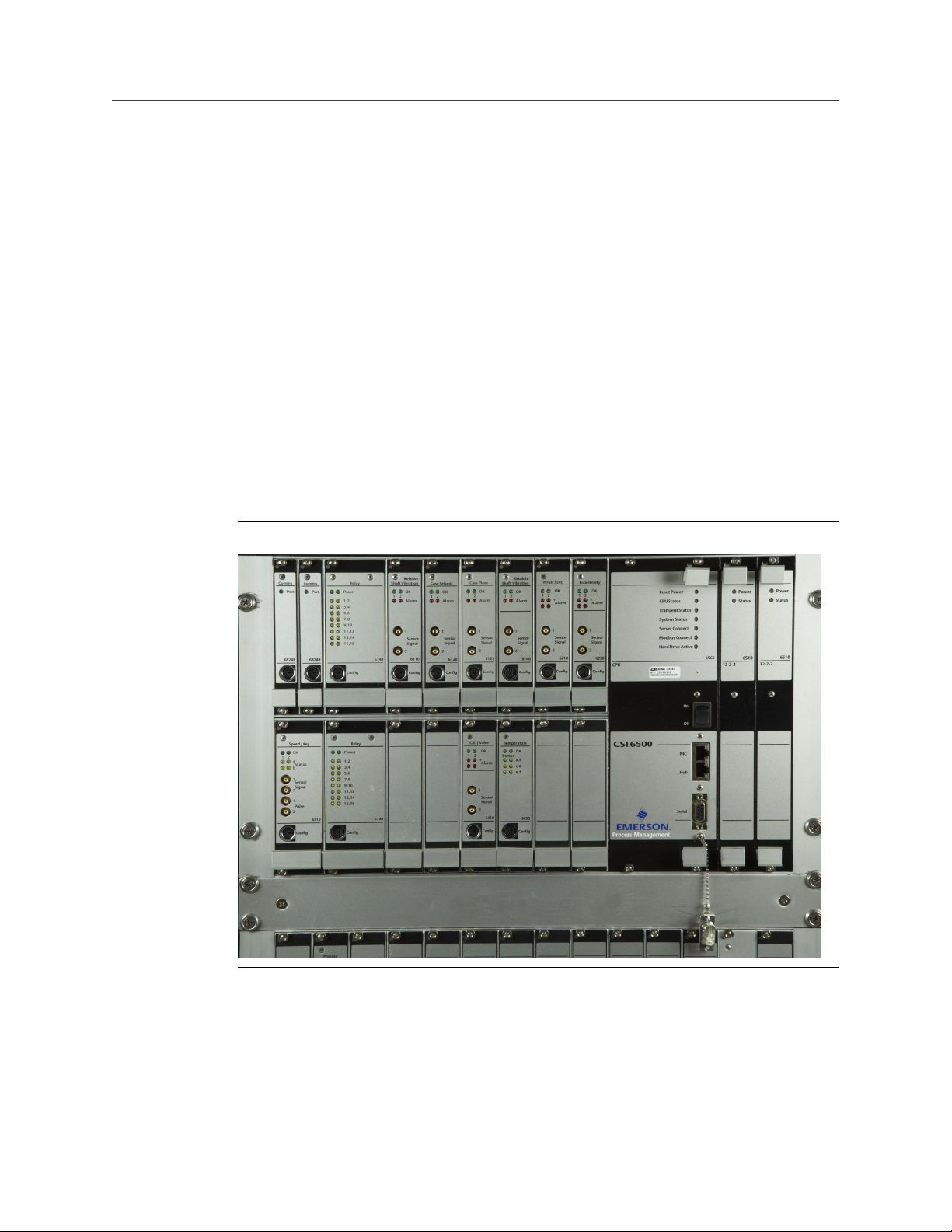
the left; the prediction modules (6U high modules) are shown on the right.
AMS 6500 with 3U and 6U high modulesFigure 4-8:
Install or remove 3U high protection module
Install or remove protection monitor cards, relay modules, and communication modules.
Protection modules are hot-swappable and can be installed or removed while the rack is
powered. Refer to the A6500 protection cards manual for instructions.
22 MHM-97125-PBF-EN, R0
Page 27
Enclosure mounting
CAUTION!
Any work at the system may impair machine protection.
Install or remove a 6U high module
WARNING!
Turn off power before installing or removing prediction cards. Prediction cards are NOT hot
swappable.
Procedure
• Install a module:
1. Line up the guide rails and push the module into the slot until fully seated.
2. Tighten the mounting screws.
• Remove a module:
1. Loosen the mounting screws.
2. Push outward on the handles to eject the module from the backplane
connectors.
3. Pull the module out of the slot by the handle.
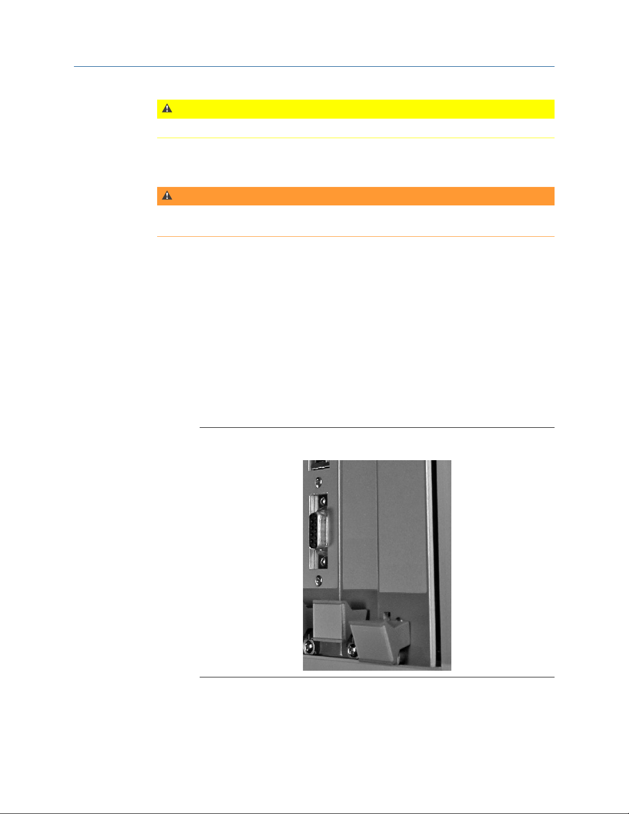
Install or remove a moduleFigure 4-9:
Use the handles to install or remove modules.
MHM-97125-PBF-EN, R0 23
Page 28

Enclosure mounting
24 MHM-97125-PBF-EN, R0
Page 29

5 Cabling requirements
Topics covered in this chapter:
• Guidelines for conduit installation
• Online instrumentation cable
• Pull cable from the junction box to the unit
• Physical network segment for the unit
• Power circuit guidelines for the unit enclosure
• Recommendations for improving signal quality
This chapter covers conduit installation guidelines, network cabling guidelines, power line
specifications, and pulling the online instrumentation cabling and multi-pair bundled cable
from junction boxes to the AMS 6500.
Cabling requirements
5.1 Guidelines for conduit installation
Note
All conduit must be bonded to earth ground and adhere to IEEE 1100 specifications for grounding.
• The following cables must be pulled in conduit:
- any cable between junction boxes and the unit
- any AMS 6500-dedicated network segment cables not pulled in existing plant
network infrastructure
- power cables for the unit power supplies
- any instrumentation cables that exceed 50 ft
• The conduit must be sized to not exceed a 40% fill.
• Steel conduit must be used. If plant codes will not allow steel conduit, contact the
project manager.
• Route conduit away from power trays according to the following guidelines:
Distance from power tray Voltage
6 in. 110 VAC
12 in. 220 VAC
24 in. 440 VAC
• Conduit must enter the unit enclosure and junction boxes from the bottom of
enclosures.
MHM-97125-PBF-EN, R0 25
Page 30

Cabling requirements
Proper conduit installationFigure 5-1:
5.2 Online instrumentation cable
The online instrumentation wiring is a polyurethane-jacketed, twisted-pair, shielded
instrumentation cable used to transmit millivolt level instrumentation signals to the online
system. The cable is designed to provide noise shielding and protection within harsh
industrial environments. It is pulled to the junction/switch boxes where it is joined to
bundled, multi-pair cabling routed back to the unit. Typically, the instrumentation-tojunction box pull is relatively short (<50 ft) and close to the machinery. It is not enclosed in
conduit except when conduit is required for specific applications. Secure exposed cabling
to machinery and plant infrastructure to avoid maintenance hazards and safety hazards.
5.2.1 Install online instrumentation cable
CAUTION!
If you are installing through conduit, the cable pull force should not exceed 25 lbs. Excessive
force will deform twisted-pair cable and degrade performance.
Procedure
1. If you are using the A612-NA-09-0 cable, apply a thin coating of dielectric grease to
the connector and screw into sensor housing using hand force only.
2. Label the cable on both ends using plant-approved wire labels. The wire label
designation must be the same on both ends of the cable.
26 MHM-97125-PBF-EN, R0
Page 31

Cabling requirements
3. Choose a physical path for the sensor cable pull according to the following
guidelines:
• Follow plant standards for segregating instrumentation, communication, and
power cable runs.
• Do not pull cable across machinery maintenance access areas such as guards,
shields, and access panels.
• Do not pull cable in machinery control/starting cable trays.
• Do not run any cable on the floor.
• Do not run cable near pathways where it will be exposed to damage from moving
machinery.
4. Starting at the sensor housing, use cable tie-downs to secure cable at 2 ft intervals
to machinery and plant infrastructure.
5. At junction/switch boxes, pull the cable through an existing PGME07 cord grip.
• Tighten the cord grip with 9/16 in. wrench until cable is secure. Do not
overtighten.
• Blunt cut the cable, leaving approximately 2 ft inside the box. Relabel the wire if
necessary.
• If you are using armored cable, remove the armor before pulling the cable
through the cord grip; cut the end of the armor with wire cutters and unravel the
length to remove. Use a heat shrink to seal the end of the armor.
5.3 Pull cable from the junction box to the unit
Use the cables in Section 5.3.1 to extend the online instrumentation wiring from the
junction boxes to the unit enclosure.
Procedure
1. Starting at the junction box, pull the cable through the conduit run.
2. At the unit enclosure, blunt cut the cable, leaving enough cable inside the enclosure
for routing to terminal connectors.
3. Label wire according to project specifications and place the label within 6 in. of the
cable access plate, with the label facing the front of the enclosure.
4. At the junction box, blunt cut the cable, leaving 2 ft inside the box for routing.
5.3.1 Recommendations for junction box-to-unit cables
Note
For cables with overall braided shield, ground the shield to the AMS 6500 enclosure.
MHM-97125-PBF-EN, R0 27
Page 32

Cabling requirements
Cable recommendationsTable 5-1:
Cable pull location Belden # Application Description
In steel conduit 9732 V707 / V727 9-pair, 24 AWG, individual foil shield, PVC jacket
9731 V727 / V745 12-pair, 24 AWG, individual foil shield, PVC jacket
In tray or aluminum
conduit
8168 V707 8-pair, 24 AWG, individual foil shield, PVC jacket, overall braid
shield
8175 V727 / V745 15-pair, 24 AWG, individual foil shield, PVC jacket, overall braid
shield
5.4 Physical network segment for the unit
Emerson recommends that customers run a dedicated physical network segment between
the database server and the unit, and follow these guidelines:
• Handling & Care Guidelines, per EIA/TIA 568/569.
Note
EIA/TIA 568/569 requires only CAT5 cabling, but Emerson recommends that customers run at
least CAT5e to be compatible with future upgrades.
• Pathways & Cable Trays, per EIA/TIA 569.
Note
Network cabling to the AMS 6500 should be in steel conduit.
5.5 Power circuit guidelines for the unit enclosure
The AMS 6500 is a laboratory grade instrument measuring millivolt level instrument
signals. The quality of the power provided to the unit is very important; follow specific
plant guidelines when running power to the unit enclosure.
Note
Adhere to IEEE 1100 specifications for powering and grounding electronic equipment.
Prediction side power specificationsTable 5-2:
DC
Nominal input voltage range 12 VDC – 24 VDC
Absolute input voltage range 10 VDC – 36 VDC
Maximum current draw 3.5 A
Nominal current draw 1.5 A
28 MHM-97125-PBF-EN, R0
Page 33

Cabling requirements
Prediction side power specifications (continued)Table 5-2:
DC
Minimum wire gauge 16 AWG
Cable Shielded twisted pair
AC
Nominal voltage 110 VAC to power 24 V power supply
Circuit breaker 10 A (with duplex receptacle)
Power ground Isolated (from production equipment)
5.5.1 Power and ground wiring on AMS 6500 backplane
CAUTION!
You cannot use the same 24 VDC source for both +24 VDC and -24 VDC. You must use separate
power supplies, or a power supply with separate, isolated outputs.
Power and ground wiring on AMS 6500 backplaneFigure 5-2:
A. +24 VDC
B. 24 VDC return
C. Cable shield or rack ground—use 14 AWG minimum wire size and ring type terminal lugs to ground
wires. Use 14 AWG minimum wire size for power wiring.
D. To rack ground—you must connect both backplane ground wires to the cabinet ground. You should
connect a separate ground wire to the 6500 rack chassis.
MHM-97125-PBF-EN, R0 29
Page 34

Cabling requirements
5.6 Recommendations for improving signal quality
The data collected by the AMS 6500 system can only be as good as the signals presented at
the AMS 6500 inputs. The system is capable of resolving microvolt-level dynamic signal
components. Typically, signals from accelerometers mounted on operating machinery are
millivolt level signals. Signals of a magnitude this low can easily be overwhelmed by
interference from many sources in an industrial environment.
5.6.1 Choosing a sensor cable
Emerson recommends low capacitance shielded-twisted-pair cable for all AMS 6500
system sensor inputs. This cable protects from low frequency interference such as 50
Hz–60 Hz sources due to conductor twisting, and from RF and static discharge sources due
to overall shielding. Conductor size may vary from 22–16 AWG.
Excessive cable capacitance will affect the high frequency response of accelerometer
signals. Emerson recommends low capacitance cable (<15 pF/ft) for longer cable runs,
especially for channels used for PeakVue measurements. There is evidence that braided
shield cables are more effective than foil shield cables because they reduce impedance of
the shield conductor. Consider using braided shield cable for long cable runs, electrically
noisy installations, or critical sensor channels.
Emerson does not recommend coaxial cable or other non-twisted cable types because
they have lower immunity to 50 Hz–60 Hz interference than twisted pair cable. When
using multiple-conductor cable, consider individual isolated shields for each twisted signal
pair and an overall shield isolated from all cable pair shields.
5.6.2 Routing sensor cables
Route sensor cables in grounded conduit or in cable trays reserved for low voltage control
type signals. Do not route sensor cables in conduit or in cable trays containing AC power
lines, including the unit enclosure cable entries. If low voltage sensor cables are routed in
cable trays containing AC power cables, line frequency components will likely be induced
into the sensor signals.
When electrical equipment is switched on or off, the changes in current can induce large
spikes in nearby sensor signals. Maintain a minimum of 3 ft between sensor lines and AC
power lines. Allow larger distances for higher voltage AC power lines.
Limit the distance of accelerometer, velometer, and passive magnetic tachometer cable to
500 ft. Limit the distance between the displacement sensor cable and the amplifier to
1,000 ft.
Note
When high amplitude, high frequency signals are measured, particularly for PeakVue measurements,
the maximum cable length may be much shorter unless low capacitance cable is used.
30 MHM-97125-PBF-EN, R0
Page 35

5.6.3 Routing Ethernet cables
Route Ethernet cables in grounded conduit or in cable trays reserved for low voltage
control type signals. Do not route Ethernet cables through conduit or cable trays
containing AC power lines. If ethernet cables are routed in cable trays containing AC power
cables, line frequency components will likely be induced into the ethernet cable.
5.6.4 Shield terminations
The shield termination of each shielded twisted pair cable requires a particular installation.
Some installations require the shield drain wire to be tied in only at the AMS 6500 input. If
the sensor cable shield drain wire is grounded at the sensor side, do not connect the shield
drain wire at the AMS 6500 input side. The shield connection at the AMS 6500 input is
connected directly to the AMS 6500 chassis ground. Therefore, if a grounded shield
connection has also been made at the sensor side, a noise current, typically at line
frequency, can flow in the shield conductor. This noise current flow will induce a noise
voltage into the sensor signal lines, causing a ground loop.
To reduce the effects of RF and static interferences, tie the sensor side shield to the sensor
side negative (–) conductor; isolate both the sensor side negative conductor and shield
from ground to prevent ground loops.
Cabling requirements
There is no comprehensive way to terminate cable shields. You may need to determine the
shield termination method on a sensor-by-sensor basis to correct the noise problems of a
particular installation.
5.6.5 Cable terminations
Terminate cables at the AMS 6500 system inputs. Do not strip the outer cable coverings
farther than necessary, and do not allow the exposed cable shields to touch. Cut the
shields to expose a minimum of unshielded signal conductors.
Clearly mark cables at the AMS 6500 inputs with labels indicating the sensor location.
Note
Do not cut unused shield drain wires; instead, fold back and tape unused shield drain wires. Later, it
may be necessary to make a double shield tie to reduce RF or static interference.
Tie overall shields in multiple conductor cables to earth ground at one end.
5.6.6 Junction boxes
In most installations, sensor cables are routed through junction boxes. When using a
junction box, maintain the cable +, –, and shield connections from input to output. Do not
allow exposed shield cables to touch, or connect to the local junction box earth ground.
Ground junction box enclosures to earth ground. If possible, route accelerometer cables
through junction boxes dedicated for accelerometers cables only. Do not route AC power
signals through a sensor junction box.
MHM-97125-PBF-EN, R0 31
Page 36

Cabling requirements
5.6.7 System grounding
Bolt the unit enclosure to a grounded beam or wall. Connect a ground bonding wire from
the unit enclosure to a nearby earth ground. Use a minimum 14 AWG stranded cable for
grounding.
Inside the unit enclosure, verify that grounding wires from the unit chassis, the unit power
supply, the enclosure frame, the enclosure door, and the AC power cable ground have
been installed; connect them to the main enclosure earth ground.
5.6.8 Operating temperature
The AMS 6500 system is designed to withstand moderate industrial conditions. To prevent
condensation and water leaks, seal the unit system enclosure and do not mount it in direct
sunlight.
AMS 6500 operation guidelines based on air temperature inside enclosureTable 5-3:
Air temperature Guideline
<-20°C (-4°F) The system should be enclosed and actively heated above -20°C (-4°F)
49-60°C
(120-140°F)
>60°C (140°F) Actively cool the system enclosure to keep system electronics below 60°C
Install a AMS 6500 cooling fan in the system enclosure.
(140°F).
Note
To maintain a consistent temperature for system operation, install a thermostat in system
enclosures that are being actively heated or cooled; keep temperatures between 10–38°C
(50–100°F).
CAUTION!
The AMS 6500 system has been tested to operate reliably up to 60°C (140°F), but the unit's
electronics will age more quickly than electronics maintained below 38°C (100°F).
32 MHM-97125-PBF-EN, R0
Page 37

6 Wire terminations
Topics covered in this chapter:
• Terminate instrumentation wiring
• Terminate bundled cable
• Wire termination at the AMS 6500
• Signal routing from the monitoring panel to the prediction panel
• Terminate discrete I/O
• Rear shield/Adapter panel—A6500-M-RSH
• Terminate +24 V power for the A6560 and A6510 modules
• Eddy Current sensor: -24 V power supply
• SysFail relay termination
• Loop interconnection for 4-20 mA current
• Terminate Ethernet connection
• Default schema for network addressing
Wire terminations
6.1 Terminate instrumentation wiring
Junction boxes have single twisted-pair instrumentation wire pulled through cable grips on
the left side of the box, and one or more bundled 9 twisted-pair cable pulled through a 1.5
in. conduit fitting on the right side of the box. Route cables through the box, leaving a
service loop, and terminate them to 3-lug terminal blocks or industry standard Phoenix
connectors.
MHM-97125-PBF-EN, R0 33
Page 38

Wire terminations
Junction box routingFigure 6-1:
A. Service loops
B. Permanent cable tie-downs
C. Sensor cables
D. Multi-pair cables
CAUTION!
Use correct gauge strippers on individual conductors. Do not strip more than 0.25 in. off a
conductor. Do not over-tighten. Turn terminal screw clockwise until you make contact with
the wire, then make an additional ¼ turn.
Note
Shield connections pass through junction boxes and are not grounded at the box.
Procedure
1. Starting at the cord grip, pull the wire to the top of the box on the left side. Pull the
service loop as shown in Figure 6-1.
2. Strip one inch of polyurethane jacket from the cable.
3. Carefully pull twisted-pair conductors out of the braided shield without removing
the braided shield.
34 MHM-97125-PBF-EN, R0
Page 39

Wire terminations
Prepare twisted-pair conductors for terminationFigure 6-2:
Spread braided shield apart and pull the conductors through the separation. Twist the braided
shield together before termination.
4. Strip 0.25 in. from each conductor and twist the end of the braided shield.
5. Terminate the wire into the proper terminal block according to the following:
a. Connect sensor positive input to the upper level of the terminal block.
b. Connect sensor negative input to the middle level of the terminal block.
c. Connect braided shield to the lower level of the terminal block.
A. Wire tag
B. White
C. Black
D. Shield
E. +
F. G. Shield
Make terminal connections with 24 AWG twisted-pair conductorsFigure 6-3:
6. Relabel the wire at the phoenix connector.
7. After all cables are terminated, bundle cables and secure against the side of the
junction box using a cable tie down.
MHM-97125-PBF-EN, R0 35
Page 40

Wire terminations
6.2 Terminate bundled cable
CAUTION!
Use correct gauge strippers on individual conductors. Do not strip more than 0.25 in. off a
conductor. Do not over-tighten. Turn terminal screw clockwise until you make contact with
the wire, then make an additional ¼ turn.
Procedure
1. Starting at the cord grip, strip cable jacket and braided shield off the cable.
2. Pull cable to the terminal block, using the following pair sequence:
Terminal block conductor pairsTable 6-1:
Terminal
Blocks Positive Conductor Negative Conductor Shield Drain
1 and 9 Yellow Black Black
2 and 10 Blue Black Blue
3 and 11 Brown Black Blue
4 and 12 Orange Black Blue
5 and 13 White Black Red
6 and 14 Red Black Red
7 and 15 Green Black Green
8 and 16 Red White Blue
Note
For a 16-channel box, start the sequence over on terminal block 9.
3. Pull individual twisted-pair (with foil shield in place) to the top of the box on the right
side. Pull service loop as shown in Figure 6-1.
4. Pull to the terminal block and blunt cut any extra wire.
5. Remove one inch of foil shield from twisted-pair and seal the foil shield using heat
shrink or electrical tape.
6. Strip 0.25 in. from each conductor and terminate to the terminal block as follows:
a. Positive Conductor on the upper level of the terminal block
b. Negative Conductor on the middle level of the terminal block
c. Shield Drain on the lower level of the terminal block
36 MHM-97125-PBF-EN, R0
Page 41

Prepare individual twisted pair cable for terminationFigure 6-4:
Measurements are not to scale.
Foil shield requires wire tag or heat shrink to prevent unraveling.
A. Foil shield
B. 24 AWG
C. Shield drain
6.3 Wire termination at the AMS 6500
Wire terminations
AMS 6500 sensor cables terminate in three different ways:
1. Directly into the 12-2-2 modules at a A6500-M-RTRM rear termination panel.
2. At the inputs on the A6500-P-RTRM termination panel. Buffered outputs can then
be routed to the 12-2-2 modules with DIP switches.
3. At DIN rail-mounted terminal blocks inside the cabinet/enclosure, then connected
to prediction modules or protection module inputs with additional short wiring
runs.
6.3.1 Rear termination panel
The rear termination panel plugs directly onto the backplane. This termination panel has
connectors for sensor inputs, tachometer inputs, and discrete input/output relays into the
12-2-2 modules. All these connections are available through BNC connectors on the rear of
the AMS 2600.
MHM-97125-PBF-EN, R0 37
Page 42

Wire terminations
A6500-M-RTRMFigure 6-5:
A6500-M-RTRMTable 6-2:
Termination panel
A
Sensor inputs: MSIG1 (Ch1–12)
B
Sensor inputs: MSIG2 (Ch13–24)
C
D
E
F
Tach inputs
Tach inputs
Relay I/O
Relay I/O
(1)
: MSIG1 (Ch1–2)
(1)
: MSIG2 (Ch 3–4)
(1)
: MSIG1 (I/O 1–2)
(1)
: MSIG2 (I/O 3–4)
38 MHM-97125-PBF-EN, R0
Page 43

Wire terminations
A6500-M-RTRM (continued)Table 6-2:
Termination panel
G DIP switches for routing buffered sensor/tach inputs from the A6500-P-RTRM side of the
rack
H DIP switches for configuring sensor power On or Off
(SW1, SW2, SW3, SW5, SW6, and SW7)
I Calibration test signal output port
(SMB connector)
J -24 V sensor power input for eddy current sensors
(1) For Tach and Relay channels, leave the sensor power DIP switches in the OFF position.
(2) SW4 and SW8 correspond to tach and relay channels, and are not used.
(2)
A6500-M-BP backplane componentsTable 6-3:
Backplane
K SysFail relay connector
L DC Power input connector for Prediction Side
M HUB network connector
N Chassis Ground lug
O NIC network connector
P Power On LED
Q +24 V Input LED
R Status LED
6.3.2 Terminate bundled cable instrumentation wiring
CAUTION!
Use correct gauge strippers on individual conductors. Do not strip more than 0.25 in. off a
conductor. Do not over-tighten. Turn terminal screw clockwise until you make contact with
the wire, then make an additional ¼ turn.
Each signal input channel has an associated DIP switch for connecting accelerometer
power. For accelerometer channels that require power, set the associated DIP switch to
the ON position. For sensor channels that do not require power from the unit, set the
associated DIP switch to the OFF position.
Procedure
1. Pull cable to the terminal blocks.
2. Secure the cable to the side of the enclosure with a cable tie down.
MHM-97125-PBF-EN, R0 39
Page 44

Wire terminations
3. Blunt cut any excess wire. Strip the cable jacket beginning where it first reaches the
terminal blocks.
4. Pull individual pairs down to the proper channel inputs on the terminal blocks.
5. Remove 1 in. of foil shield and place a wire label around the end of the foil shield.
Wire label must match the sensor wire label in the junction box.
6. Strip 0.25 in. from each conductor and terminate to the screw terminals following
the pinouts in Section 6.3.3.
7. Document the sensor name, wire label name, and unit channel number on the cable
administration chart.
Signal, Tachometer, and I/O module wiring notes
Signal, Tachometer, and I/O module wiring notesFigure 6-6:
A. Strip the insulation and shield as close to the terminal block as possible.
B. Maintain cable pair twists as close to the terminal block as possible.
C. Connect the cable shield on only one end. Prioritize connecting the shield on the sensor end.
D. Connect the multiple-pair cable shield drain wire to earth ground on only one end.
E. Do not allow shield drain wires or foil from individual cables to short. Use heat shrink and dress
wire ends as necessary.
6.3.3 Terminal descriptors
Each channel has five terminals. The first two are for the plus (+) and minus (-) signal
inputs. If the associated DIP switch is set to ON, these terminals will also supply +24 V
constant current accelerometer power.
40 MHM-97125-PBF-EN, R0
Page 45

Wire terminations
The second two are for the -24 V power supply for eddy current probes. These terminals
only supply power if an external -24 V power supply is connected to the J19 power input
terminal at the edge of the termination panel.
The last terminal for each channel is a chassis ground for connecting the sensor cable
shield.
MHM-97125-PBF-EN, R0 41
Page 46

Wire terminations
Terminal descriptors for MSIG 1Table 6-4:
J1 J2 J3 J4
SIG+1/+24 V
SIG-1/+24 V return SIG-5/+24 V return SIG-9/+24 V return Tach-1
CH1
-24 V -24 V -24 V -24 V
Gnd (-24 V return) Gnd (-24 V return) Gnd (-24 V return) Gnd (-24 V return)
Chassis GND (Shield) Chassis GND (Shield) Chassis GND (Shield) Chassis GND (Shield)
SIG+2/+24 V
SIG-2/+24 V return SIG-6/+24 V return SIG-10/+24 V return Tach-2
CH2
-24 V -24 V -24 V -24 V
Gnd (-24 V return) Gnd (-24 V return) Gnd (-24 V return) Gnd (-24 V return)
Chassis GND (Shield) Chassis GND (Shield) Chassis GND (Shield) Chassis GND (Shield)
SIG+3/+24 V
SIG-3/+24 V return SIG-7/+24 V return SIG-11/+24 V return I/O-1
CH3
-24 V -24 V -24 V -24 V
Gnd (-24 V return
(1)
) Gnd (-24 V return
Shield Shield Shield Shield
SIG+4/+24 V
SIG-4/+24 V return SIG-8/+24 V return SIG-12/+24 V return I/O-2
CH4
-24 V -24 V -24 V -24 V
Gnd (-24 V return) Gnd (-24 V return) Gnd (-24 V return) Gnd (-24 V return)
Chassis GND (Shield) Chassis GND (Shield) Chassis GND (Shield) Chassis GND (Shield)
CH5
CH6
CH7
CH8
SIG+5/+24 V
SIG+6/+24 V
SIG+7/+24 V
SIG+8/+24 V
SIG+9/+24 V
CH9
SIG+10/+24 V
CH10
SIG+11/+24 V
CH11
(1)
) Gnd (-24 V return
SIG+12/+24 V
CH12
Tach+1
TACH1
Tach+2
TACH2
I/O+1
I/O1
(1)
) Gnd (-24 V return
I/O+2
I/O2
(1)
)
(1) -24 V terminals on I/O channels are not used for I/O connections.
42 MHM-97125-PBF-EN, R0
Page 47

Terminal descriptors for MSIG 2Table 6-5:
J5 J6 J7 J8
SIG+13/+24 V
SIG-13/+24 V return SIG-17/+24 V return SIG-21/+24 V return Tach-3
CH13
-24 V -24 V -24 V -24 V
Gnd (-24 V return) Gnd (-24 V return) Gnd (-24 V return) Gnd (-24 V return)
Shield Shield Shield Shield
SIG+14/+24 V
SIG-14/+24 V return SIG-18/+24 V return SIG-22/+24 V return Tach-4
CH14
-24 V -24 V -24 V -24 V
Gnd (-24 V return) Gnd (-24 V return) Gnd (-24 V return) Gnd (-24 V return)
Shield Shield Shield Shield
SIG+15/+24 V
SIG-15/+24 V return SIG-19/+24 V return SIG-23/+24 V return I/O-3
CH15
-24 V -24 V -24 V -24 V
Gnd (-24 V return) Gnd (-24 V return) Gnd (-24 V return) Gnd (-24 V return)
Shield Shield Shield Shield
SIG+16/+24 V
SIG-16/+24 V return SIG-20/+24 V return SIG-24/+24 V return I/O-4
CH16
-24 V -24 V -24 V -24 V
Gnd (-24 V return) Gnd (-24 V return) Gnd (-24 V return) Gnd (-24 V return)
Shield Shield Shield Shield
CH17
CH18
CH19
CH20
SIG+17/+24 V
SIG+18/+24 V
SIG+19/+24 V
SIG+20/+24 V
CH21
CH22
CH23
CH24
SIG+21/+24 V
SIG+22/+24 V
SIG+23/+24 V
SIG+24/+24 V
Tach+3
TACH3
Tach+4
TACH4
I/O+3
I/O3
I/O+4
I/O4
Wire terminations
6.4 Signal routing from the monitoring panel to the prediction panel
You can set DIP switches on the A6500-M-RTRM termination panel to route sensor and
tachometer signals from the A6500-P-RTRM termination panel. Set these switches to the
ON position to connect to their respective A6500-P-RTRM buffered outputs. See
Rear termination panel for DIP switch locations.
The external input connectors on the A6500-M-RTRM are connected to the 12-2-2 module
signal inputs, regardless of whether the DIP switches are set to ON or OFF. Therefore, if a
DIP switch is set to route an input from the A6500-P-RTRM, do not connect an external
sensor to the associated external input of the A6500-M-RTRM. Set the DIP switches for
accelerometer power to OFF while routing inputs from the A6500-P-RTRM.
MHM-97125-PBF-EN, R0 43
Page 48

Wire terminations
6.4.1 Signal input cross reference
AMS 6500 rear termination panel with signal input cross referencesFigure 6-7:
A6500-M-RTRM signal inputsTable 6-6:
A6500-M-RTRM inputs Output Connector label
Sensor inputs 1–12 A6500-P-RTRM buffered output, monitor positions 1–6 XR11–XR64
Sensor inputs 13–24 A6500-P-RTRM buffered output, monitor positions 7–12 XR71–XR125
Tach inputs 1 and 3 (T1 &
T3)
Tach inputs 2 and 4 (T2 &
T4)
Relay I/O channels 1–4 not connected not used
A6312 pulse output, channel 1 (T1) XR131
A6312 pulse output, channel 2 (T2) XR132
6.5 Terminate discrete I/O
CAUTION!
Use correct gauge strippers on individual conductors. Do not strip more than 0.25 in. off a
conductor. Do not over-tighten. Turn terminal screw clockwise until you make contact with
the wire, then make an additional ¼ turn.
44 MHM-97125-PBF-EN, R0
Page 49

Wire terminations
Procedure
1. Pull cable to the I/O relay channel inputs on the termination panel.
2. Blunt cut excess wire. Strip 1 in. from the cable jacket and 0.25 in. from each
conductor.
3. Terminate according to Table 6-4, and the following:
Relay Excitation Voltage SIG+
Voltage Return SIG-
Shield Drain Shield
4. Relabel wire at the connector.
5. After all wires are pulled, bundle the wires, and secure the bundle to the side of the
enclosure.
6. Document the discrete I/O name, wire label name, and the AMS 6500 channel
number on the cable administration chart.
Discrete I/O cable terminationFigure 6-8:
MHM-97125-PBF-EN, R0 45
Page 50

Wire terminations
6.6 Rear shield/Adapter panel—A6500-M-RSH
The rear shield panel is a modified version of the front termination panel. It routes signals
to the backplane (A6500-M-BP) from the front termination panel instead of the rear
termination panel.
If you will route all sensor and tach inputs from the A6500-P-RTRM, you can use the rear
shield panel (A6500-M-RSH) instead of the rear termination panel (A6500-M-RTRM). The
rear shield panel provides a simpler adapter for Jumper connections to the A6500-P-RTRM
sensor and tach signals, and connectors for the 4 external relay I/O termination.
6.7 Terminate +24 V power for the A6560 and A6510 modules
The +24 V power input for the A6560 and A6510 prediction modules is located on the
A6500-M-BP backplane. This connector is isolated from the protection modules, which are
powered separately. Emerson recommends a separate power supply for protection
modules.
CAUTION!
• The AMS 6500 +24 V power terminals are not wired the same as the CSI 4500 power
terminals. Do not use a connector that was previously wired for a CSI 4500 without
reconfiguring the wiring.
• The +24 V power input for the A6560 and A6510 modules requires a +24 V power supply.
Do not connect the -24 V power supply intended to power the Eddy Current sensor to
this input. Verify all power supply connections are wired and connected properly before
powering the unit.
Procedure
1. Route cable to the power connector.
2. Leave a service loop.
3. Strip conductors 0.25 in. and terminate to Phoenix connections according to the
following diagram:
Power termination for A6560 and A6510 prediction modulesTable 6-7:
Wire Termination panel
+DC +
-DC -
Shield SHLD
46 MHM-97125-PBF-EN, R0
Page 51

Note
When connecting a 24 V power supply to the AMS 6500, connect the DC side of the power
supply to the AMS 6500 before connecting the AC side of the power supply to AC line power.
4. Secure the power cable to the side of the enclosure with a cable tie-down.
6.7.1 Power input specifications
Power input specificationsTable 6-8:
Power requirement Range
DC input voltage 18–31 VDC
(24 VDC nominal)
DC input current (with Transient) 1.0 A @ 24 VDC (no termination panel)
1.25 A @ 24 VDC (with termination panel, all channels
powered)
DC input current (without Transient) 0.65 A @ 24 VDC (no termination panel)
0.9 A @ 24 VDC (with termination panel, all channels
powered)
Maximum input surge current (all
versions)
Maximum power dissipation 22 W
7 A @ 24 VDC for 1 ms
3 A @ 24 VDC for 20 ms
30 W with Transient
Wire terminations
6.8 Eddy Current sensor: -24 V power supply
The power input connector for Eddy Current sensors is located on the A6500-M-RTRM.
When using Eddy Current sensors, feed in a -24 V sensor supply at this connector. This
connector then supplies all the -24 V sensor supply terminals on the termination panel.
The supply terminals at each channel have built-in auto-resetting breakers to protect
against a short circuit on one channel disrupting the power supply for all channels.
Note
The AMS 6500 performs an internal test to verify that -24 V power is connected. If a -24 V supply is
not connected, the CPU Status LEDs on the CPU, and the Status LED on the left side of the
termination panel will turn from green to red. If Eddy Current sensor power is not required, this
internal test can be disabled by installing a jumper on the termination panel at the pins labeled -24
V Disable.
MHM-97125-PBF-EN, R0 47
Page 52

Wire terminations
CAUTION!
The -24 V Eddy Current sensor power input requires a -24 V power supply. Do not connect the
+24 V power supply intended for powering the A6560, A6560R, or A6510 to this input. Verify
all power supply connections are wired and connected properly before powering the unit.
6.9 SysFail relay termination
The SysFail relay output connector is labeled SYSFAIL RELAY, and located on the
bottom left corner of the A6500-M-BP backplane.
The SysFail relay output can be terminated as either normally-open (terminate to C and
NO) or normally-closed (terminate to C and NC).
CAUTION!
The SysFail relay connection is an output for relays only. Do not connect the +24 V power
supply intended for powering the A6560, A6560R or A6510, or the -24 V power supply
intended for Eddy Current Probe power to this output. Verify all power supply connections are
wired and connected properly before powering the unit.
6.10 Loop interconnection for 4-20 mA current
To convert the milliamp signal to a voltage signal, install a 250 ohm resistor between the +
and - signal inputs when connecting 4-20 mA signal inputs.
48 MHM-97125-PBF-EN, R0
Page 53

Wire terminations
AMS 6500 transmitter connection for 4-20 mA currentFigure 6-9:
A. AMS 6500 input sensors
B. 250 ohm resistor
C. 4-20 mA transmitter
Note
AMS 6500 MUX (SIG) channels do not provide loop power to 4-20 mA devices. A separate module is
required to provide loop power.
6.11 Terminate Ethernet connection
CAUTION!
Do not daisy-chain multiple units using the NIC or HUB. If one network connection fails, it will
disrupt network communication for multiple units.
Procedure
1. Route the network cable to RJ45 connectors, at either the front of the A6560
module, or at the rear of the A6500-M-BP backplane.
2. Blunt cut excess wire and attach the RJ45 CAT5 according to your plant's standards
for 10/100 Base-T connections.
MHM-97125-PBF-EN, R0 49
Page 54

Wire terminations
3. Connect the terminated Ethernet cable to the NIC.
4. Secure the network cable to the right side of enclosure using a cable tie-down.
NIC and HUB connectorsFigure 6-10:
A. Rear HUB connector
B. Rear NIC connector
Use the NIC connector when connecting to an Ethernet hub or switch.
Use the HUB connector when connecting directly to a PC (the HUB connector provides the
same function as a crossover cable).
6.12 Default schema for network addressing
The network arrangement shown assumes one of the AMS 6500 units include Transient
functionality.
50 MHM-97125-PBF-EN, R0
Page 55

Wire terminations
Default schema for network addressingFigure 6-11:
MHM-97125-PBF-EN, R0 51
Page 56

Wire terminations
52 MHM-97125-PBF-EN, R0
Page 57

7 Hardware configuration
Topics covered in this chapter:
• Hardware configuration: overview
• The A6560R and A6510 modules
• Configure the A6560R with a terminal emulator
7.1 Hardware configuration: overview
The AMS 6500 Machinery Health™ Monitor (A6560R CPU module, in combination with the
A6510 Signal Input module), is a multi-channel, multi-tasking, multi-processor data
acquisition system primarily intended for monitoring heavy industrial rotating machinery.
Typical signal inputs are dynamic AC machine vibration signatures from accelerometers,
velocity probes, or eddy current sensors. These signals include two components: the
dynamic AC component, which represents machine vibration, and a DC component, which
represents the sensor bias level. In the case of an eddy current sensor, the DC component
represents the gap, or average distance between the probe tip and the machine shaft.
Other signal inputs include process signals; these are DC parameters such as temperature
or pressure.
Hardware configuration
Tachometer inputs are used to determine machine speed. These tachometer signals are
typically generated from an eddy current sensor or passive magnetic sensor positioned at
a machine shaft keyway or gear, producing a pulse train (not necessarily 1x machine
speed) representing the machine phase and running speed.
Discrete inputs represent machine states such as running, off, and starting. These inputs
are used to control or modify the data acquisition based on machine state. Common state
control inputs are relay closures or machine RPM. AC or DC signal levels can also be used
for state control.
7.1.1 Gross Scan monitoring
Gross Scan monitoring includes:
• the acquisition of the overall level of the dynamic AC vibration signal, typically the
RMS value of the signal.
• the DC sensor bias level.
• the measurement of a DC process signal.
All these signal inputs are DC values (the RMS value is a DC value proportional to the
overall energy content of the AC signal). The Gross Scan inputs are multiplexed into a fast
successive approximation ADC controlled by the A6560R CPU module. Gross Scan
monitoring measures all input channels AC+DC twice per second. When the Transient
option is included, true waveform peak-to-peak may be included in Gross Scan
monitoring.
MHM-97125-PBF-EN, R0 53
Page 58

Hardware configuration
7.1.2 Spectral Scan
Spectral Scan is defined as the acquisition and analysis of dynamic AC signals only. The
signals are acquired, two channels at a time (referred to as CHX and CHY). Preprogrammed
groups of Spectral Scan measurement parameters (AP Sets) may be assigned to specific
machine state conditions to tailor data acquisition to specific machine operational states.
7.1.3 Transient data capture
Transient data capture is the acquisition of continuous time waveforms of dynamic AC
signals. Transient data is captured in parallel for all channels. Other data stored along with
the Transient data include Gross Scan data captured once per second, tach pulse records,
and acquisition timestamps. The Transient data is stored on hard disk, and is available for
real-time analysis via Ethernet.
7.2 The A6560R and A6510 modules
The AMS6500M has an A6560R Processor module and either one or two A6510 Signal
Input modules.
The AMS6500T has an A6560R Processor module with a solid-state drive and either one or
two A6510 Signal Input modules, each with Transient Filter Boards.
7.2.1 A6560R Processor module
The A6560R Processor module provides all data acquisition, data storage, and data
communication functions for the AMS 6500 system and the AMS 2600 system. The
A6560R is capable of up to 24 simultaneous, continuous waveform measurements for
detailed Spectral analysis, up to 24 RMS and DC values for Gross Scan measurements, up
to 4 tachometers for machine speed measurement, and up to 4 digital state inputs.
Gross Scan values, tachometer values, and digital input states may be combined logically
to determine machine operating state and define specific data acquisition states. The
system can be configured to transmit and store data on either time interval or based on
the amount of change of the data values.
The Processor module provides four 100 Base-T Ethernet ports and one RS-232 serial port
for system communications and diagnostics. Additional connections are available for the
calibration signal and a dry contact SPDT SysFail relay. This relay is energized when the
Processor CPU successfully boots. On a CPU failure or power loss, the relay will deenergize.
The Processor module may be configured to download its operational firmware via
Ethernet upon boot, or to operate on firmware that has been stored in FLASH memory.
The Processor module has an on-board signal generator capable of producing sinusoidal
and DC signals that are routed to the input modules during system calibration and on
Power On Self Test (POST).
54 MHM-97125-PBF-EN, R0
Page 59

Hardware configuration
Note
If the unit experiences frequent extreme temperature changes, recalibrate the signal generator
more frequently.
The Processor module automatically detects input module type and configuration, and
only permits database configuration based on the existing channel set.
A6560R Processor moduleFigure 7-1:
MHM-97125-PBF-EN, R0 55
Page 60

Hardware configuration
Transient capability
The A6560R CPU module, is capable of parallel, continuous time waveform acquisition on
all channels. All collected time waveform data, along with Gross Scan data and up to four
tachometer pulse records, is stored on an internal solid-state drive (SSD). The SSD is
specially rated for industrial operation and provides approximately 100 hours of DCR
(Digital Condition Recorder) transient data. There is also room on the drive to store
transient archives manually and automatically.
Transient data can be streamed via Ethernet to analysis applications in near real time,
without affecting data collection or on-board data storage.
While collecting time waveforms and tachometer pulses, the processor continuously
calculates the peak-to-peak value of each channel's waveform. When configured, this
value can be used as the Gross Scan instead of the RMS value produced by the A6510
Signal Input module.
A6560R CPU module with and without Transient capabilityFigure 7-2:
An A6560RT with mounted SSD. An A6560R next to the older A6560RT.
A. SSD
Replace the Transient SSD
Only replace the Transient SSD if directed by Emerson Product Support.
CAUTION!
Follow the same safety precautions as replacing a card in the unit. Always power down the
unit.
56 MHM-97125-PBF-EN, R0
Page 61

Hardware configuration
Procedure
Replace the SSD as directed by Emerson Product Support.
Postrequisites
Format the Transient SSD.
Format the Transient SSD
You must format the new solid-state drive before you can use it.
Procedure
1. Power on the system and ignore any hard drive error messages on the
HyperTerminal monitor.
2. When the system has booted, launch DHM_III.exe.
DHM_III.exe is located at C:\inetpub\ftproot\bin\Tools directory.
3. In DHM, connect to the unit in "Single User" mode.
4. From the main menu, select Transient > Format Hard Drive.
5. When the drive has been formatted, reboot the unit. Ignore any hard drive error
messages.
When the POST process is complete, the firmware automatically prepares the hard
drive with the Transient File System. This process can take up to 15 minutes.
6. Disconnect DHM.
The unit will reboot automatically.
When the unit boots, there should be no hard drive error messages. If configured,
Transient data collection should begin, indicated by a flashing hard drive indicator on the
A6560R CPU module front panel.
7.2.2 A6510
The A6510 combines the features of Signal Input, Tachometer Input, and I/O Relays to
allow a combination of sensor and relay types in one module.
The A6510 provides 12 channels of vibration or process sensor inputs, 2 channels of
tachometer sensor inputs, and 2 optically-isolated I/O relay channels.
MHM-97125-PBF-EN, R0 57
Page 62

Hardware configuration
A6510Figure 7-3:
Transient Filter Board for the A6510
The Transient Filter Board provides parallel anti-aliasing filters for the signal channels on
the Signal Input module. Either one or two Transient Filter Boards may be used to
configure either a 12- or 24-channel Transient System.
When installing the Transient Filter Board on the Signal Input module, make sure both
mating connectors are fully engaged, then install all six mounting screws.
58 MHM-97125-PBF-EN, R0
Page 63

Hardware configuration
Transient Filter Board PCB mounted on a Signal Input moduleFigure 7-4:
A. Mounting screw positions
B. Transient Filter Board
C. I/O relay DIP switches
Vibration signal inputs
The vibration sensor types include accelerometer, passive velocity, active velocity, and
displacement. The A6510 Signal Input module will also accept non-specific AC or DC
inputs from any source that conforms to the A6560R input range limits.
The vibration inputs provide the following programmable functions for each channel:
Input Attenuator /1, /2, Gain x1, x10, integrator on/off. In Table 7-1, the combination of
input attenuator and gain setting provide four input range combinations.
Signal Input module input rangesTable 7-1:
Attenuator Gain Input Range +/-
/2 x1 10.0 V
100 g
100 ips
50 mil
/1 x1 5.0 V
50 g
50 ips
25 mil
MHM-97125-PBF-EN, R0 59
Page 64

Hardware configuration
Signal Input module input ranges (continued)Table 7-1:
Attenuator Gain Input Range +/-
/2 x10 1.0 V
10 g
50 ips
5 mil
/1 x10 0.5 V
5 g
5 ips
2.5 mil
The integrator allows acceleration signals to be converted to velocity.
The A6510 Signal Input module selects 2 of the 12 vibration channels at a time and routes
them to the Processor module for spectral analysis. The RMS and DC signals are routed to
the Processor module for Gross Scan collection.
The Transient Filter Board is required for Transient data acquisition.
To measure 4-20 mA signals, add a resistor across the channel input. A typical value is 250
ohms, which converts 4-20 mA to 1-5 V. Maximum series resistor value is 1000 ohms.
Tachometer inputs
The Tachometer inputs allow measurement of two pulse tachometer sources per module.
Tachometer sensor types may include, but are not limited to: eddy current sensor, Hall
effect sensor, or TTL pulse type from various sources.
The Tachometer Input module features either fixed voltage trigger or “adaptive”
automatic triggering. Triggering parameters may be set independently for each
tachometer sensor input.
An input gain selection of x1 or x5 may be selected for each channel. A gain of x5 is
recommended for tachometer inputs smaller than 1 V pk-pk. If the x5 input gain is used,
care should be taken to make sure that the input signal remains within +/-24 V, including
any sensor bias or gap voltage.
I/O relay channels
Each A6510 Signal Input module has two I/O relay channels that provide optically isolated
discrete inputs or dry contact outputs. Inputs can be between 5 V and 24 VDC. Outputs are
limited to 24 VDC @ 0.5 A.
Note
AC relays are not provided.
60 MHM-97125-PBF-EN, R0
Page 65

Hardware configuration
Signal Input module PCBFigure 7-5:
A. I/O relay DIP switches
Each I/O Relay channel on the A6510 Signal Input module contains both input and output
hardware. The relays are configurable as either input or output relays, with a DIP switch
(SW) on the circuit board. A relay channel that is configured in software cannot be used
unless the corresponding DIP switch is set to the correct position. The firmware will detect
the DIP switch state at startup and generates a flag in the Telnet session if the software
configuration does not match the DIP switch setting. The DIP switches are used to protect
a user input device from inadvertently being shorted by a relay output configuration.
Set the corresponding DIP switch to the ON position for output relays, and to the OFF
position for input relays. The factory default state of the DIP switches is OFF (Input). DIP
switch 1 is for the first relay channel and DIP switch 2 is for the second relay channel.
The shelf-state of the output relays is normally open, meaning that when the power to the
unit is disconnected, the relays are open. While operating the unit, the relays are typically
closed until activated by an alarm, but they can be configured either way.
MHM-97125-PBF-EN, R0 61
Page 66

Hardware configuration
7.3 Configure the A6560R with a terminal emulator
7.3.1 Configure a serial port connection from a computer
Use a terminal emulator such as Telnet or HyperTerminal to connect to the AMS Machinery
Health Monitor using a serial cable or an Ethernet cable.
Table 7-2 in the terminal emulator's connection settings.
Prerequisites
You need a username and password to log on to a AMS Machinery Health Monitor with
Telnet.
Serial port connection setupTable 7-2:
Setting Value
serial port COM1
baud rate 9600
data bits 8
stop bit 1
parity none
flow control none
(1)
Configure the settings in
7.3.2 Configure A6560R boot parameters with a terminal emulator
During normal usage, it is unlikely that you will need to change the initial boot parameters.
However, you may need to change boot settings in two situations:
• If you replace the processor module. You may replace an A6560 with an A6560R.
• The unit is added to an existing Ethernet network that is not directly connected to
the online server through a dedicated cable.
Note
Do not add a unit to an existing network until its processor board IP addresses have been
verified and changed, if necessary, to be compatible with addresses already in use on the
existing network.
Procedure
1. Start a terminal session, and turn the unit on.
(1) Telnet and HyperTerminal are Windows Features that are available but are not enabled by default. You can use other terminal emulator
programs.
62 MHM-97125-PBF-EN, R0
Page 67

Hardware configuration
A screen similar to the following will appear during the boot process:
VxWorks System Boot
Copyright 1984-2016 Wind River Systems, Inc.
CPU: Freescale P1010E — Sty Engine
Version: VxWorks 6.9
BSP version: 6.9/5.00g
Creation date: Jul 18 2016 09:26:09
Press any key to stop auto-boot...
2. When the boot process has completed, type bootChange and press Enter to configure
the unit. This command is case-sensitive.
Important
If a gateway is used on the network, the address must be specified as a boot parameter.
A list of boot parameters appears one line at a time. When configuring the A6560R,
the screen will look similar to this:
boot device : motetsec0
processor number : 0
host name : host
file name : bin/6500R
inet on ethernet (e) : 192.168.0.10:ffffff00
inet on backplane (b) :
host inet (h) : 192.168.0.1
gateway inet (g)* :
user (u) : anonymous
ftp password (pw) (blank = use rsh) :
flags (f) : 0x1008
target name (tn) :
startup script (s) :
other (o) :
CAUTION!
Only change boot flags under the direction of Emerson Product Support.
If allowed to complete without interruption, the boot process should finish with a screen
similar to this:
MHM-97125-PBF-EN, R0 63
Page 68

Hardware configuration
Cfg Table Last "Put" Time
------------- ---------------------
DIO 2008-08-13 19:09:25
GS 2008-08-13 19:09:25
TACH 2008-08-13 19:09:25
SCHED 2008-08-13 19:09:26
PRED 2008-08-13 19:09:25
LIMIT 2008-08-13 19:09:26
TRANS 2008-08-13 19:09:29
EGU_FAC Default Table
EGU_ASN Default Table
BRS_initRamdisk_i32f: No browser disk image found in FLASH
Initializing empty browser RAM disk /browser...Succeeded.
/browser/ - Volume is OK
Base Modbus register table size (excluding DCS info): 0xcf8a (53130)
This unit will begin announcing its availability in 84 seconds
0x7942148 (t_startup): HLTMON_sysCheck_i32f: All expected modules were successfully
registered
7.3.3 Console session navigation after boot interrupt
You may interrupt the boot process by immediately pressing Space after the VxWorks
copyright is displayed. If you interrupt the boot process, use the following commands to
navigate the boot configuration menu.
The most commonly used commands are ?, @, p, and c.
Note
When modifying an entry, type the new setting. Do not attempt to backspace over an existing entry.
CAUTION!
Use only the first four commands (?, @, p, c) in Table 7-3 to navigate in a console session.
Contact Emerson Product Support before using any other commands.
VxWorks commands are case-sensitive.
Console session navigation after boot interruptTable 7-3:
Command Description
? Print this list
@ Continue boot (load and go)
64 MHM-97125-PBF-EN, R0
Page 69

Hardware configuration
Console session navigation after boot interrupt (continued)Table 7-3:
Command Description
p Print boot parameters
c Change boot parameters
e Print fatal exception
v Print version
M Change MAC address
7.3.4 Console session navigation after boot complete
After typing bootChange in a console session, use the following commands to navigate:
Note
When modifying an entry, type the new setting. Do not attempt to backspace over an existing entry.
VxWorks commands are case-sensitive.
Console session navigation commandsTable 7-4:
Key sequence Description
Enter Accept the value.
. (period) Clear the value when you press the period key followed by Enter.
– (dash) Go back to the previous parameter when you press dash followed
safeReboot_vf Reboot the system with new boot settings.
7.3.5 Boot flags
For the A6560R, you can list boot flags by typing a question mark (?) into in a console
session at the VxWorks boot prompt.
Boot flags below are expressed in hexadecimal. To activate more than one boot flag at the same
time, add them together using the Windows Calculator. Select View > Programmer, and select the Hex
radio button.
Complete list of boot flagsTable 7-5:
by Enter.
Boot Flag Description
0x0002 Load local system symbols (for debug).
0x0004 Don't autoboot (for testing).
0x0008 Quick autoboot (no countdown).
0x0040 Use DHCP to get IP address parameters (not recommended).
MHM-97125-PBF-EN, R0 65
Page 70

Hardware configuration
Complete list of boot flags (continued)Table 7-5:
Boot Flag Description
0x0080 Use TFTP to get boot image (network boot only).
0x0200 Ignore BOOTROM update image in FLASH (for testing).
0x1000 Attempt network, fallback on FLASH boot (legacy 4500 mode).
0x2000 Boot ALWAYS from network, never fallback on FLASH.
0x4000 Boot ONCE from network. This flag clears itself after one boot.
0x8000 Boot over a WAN, requiring extended FTP timeouts. This flag applies only if one of
the following flags is set:
• 0x1000
• 0x2000
• 0x4000
7.3.6 Subnet masks
A subnet mask is normally represented as a series of four decimal numbers, each of which
can have a value from 0 to 255, separated by periods (255.255.248.0).
In the system boot parameters, the subnet mask is represented as a series of four
hexadecimal pairs with no separators (that is, 255.255.248.0 is represented as fffff800). A
hexadecimal conversion table can be used to convert the subnet mask numbers from
decimal to hexadecimal. The calculator in the Windows Accessories folder will also
perform this conversion when it is set to Programmer Mode.
Specify a subnet mask
The subnet mask on an A6560R Processor module defaults to 255.255.255.0 (ffffff00).
Procedure
1. The subnet mask should be set to match the subnet mask used on the server
computer or laptop.
If they do not match, network communication failure is possible.
2. Subnet mask is applied on the IP address of the system boot parameter inet on
ethernet. Enter the IP address of the unit followed by a colon and then the subnet
mask in the hexadecimal format.
66 MHM-97125-PBF-EN, R0
Page 71

8 Software configuration
Topics covered in this chapter:
• System overview diagram
• System configuration overview
• Install AMS Machinery Manager
• Configure the FTP server to download firmware
• Connect the A6560R CPU to AMS Machinery Manager
8.1 System overview diagram
System overview diagramFigure 8-1:
Software configuration
• Network Server—Service responsible for handling the user's access to the various
programs within the AMS Machinery Manager software.
• Online Watch (O_Watch)—Graphic interface that allows:
- viewing of data sent to the server by the A6560R CPU module
- management of transient acquisition and auto-extraction
- adjustment of alarm levels
- on-demand data acquisition
MHM-97125-PBF-EN, R0 67
Page 72

Software configuration
• Online Configuration (O_Config)—Program that allows the creation and modifying
of databases for use with the online system, along with system commissioning.
• Vibration Analysis (Diagnostics)—Application that allows the user to request and
save transient data and view live streaming data. It provides a variety of analysis
functions necessary for analyzing the data generated by the AMS 6500 or AMS 2600.
• CSIMtDbMgr Service—Handles most of the reading and writing operations
performed on databases stored on the server. It also indexes and verifies the
integrity of databases.
• Online Server (O_Server)—The central process service which handles all predictive
activity on the online system. It is responsible for processing requests from the
client, sending configuration information to the AMS 6500 or AMS 2600.
• MHM Remote—Service that handles transient data generated by the AMS 6500 or
AMS 2600, and database access required by the Vibration Analysis program.
• AMS 6500 or AMS 2600 — Hardware portion of the monitoring system. The AMS
6500 is a fixed installation of the monitoring unit and the AMS 2600 is a portable
unit that is connected to the server through Ethernet. Both the AMS 6500 and AMS
2600 use the A6560R with A6510 modules.
• IIS FTP—Microsoft's IIS includes an FTP server which needs to be installed to allow the
A6560R to load firmware from the server.
• Firmware—The firmware for the A6560R is loaded from the computer when the unit
powers on. This allows system updates to be installed on the computer like any
other program update without the requirement of any special interaction with the
A6560R beyond rebooting it to allow the new version to load.
8.2 System configuration overview
The A6560R CPU module communicates through an Ethernet connection. When you are
using the AMS 6500, AMS Machinery Manager is on a server and connected through a
network. When you are using the AMS 2600, the AMS Machinery Manager is on a laptop
and connected directly to the unit.
In order for the unit and the server to successfully communicate, both must have
addresses known to each other. Also, A6560R must contain the IP address of the FTP
server from which to download firmware updates.
1. Set up the computer:
• Set the computer's IP address, as needed.
• Install AMS Machinery Manager on the computer as a Network system.
• Set up an FTP server to host the firmware, as needed.
• Install the A6560R firmware on the FTP server.
2. Set up the unit to communicate with AMS Machinery Manager.
• Connect the computer to the unit with an Ethernet or Serial cable
• Connect to the unit from a computer using a terminal emulator.
• Set the unit's IP address.
68 MHM-97125-PBF-EN, R0
Page 73

Software configuration
• Set the IP address of the FTP server for the unit to obtain firmware updates.
3. Connect equipment to be monitored to the unit:
a. In AMS Machinery Manager, add an online server to RBM Network
Administration.
b. In Online Configuration, add the unit's IP address, create a database for the
equipment to be monitored, and save it to the unit.
4. Set up the database in AMS Machinery Manager:
a. In AMS Machinery Manager, add an online server to RBM Network
Administration.
b. In Online Configuration, add the unit's IP address, create a database that
matches the configuration of the equipment to be monitored, and save it to the
unit.
Note
If a computer is purchased from Emerson with the AMS 2600 order, the computer and the unit are
already set up.
8.3 Install AMS Machinery Manager
Install AMS Machinery Manager on your computer with the following options checked:
• Network Server
• Online Server
• AMS Machinery Manager Client
Refer to your software user guide for these details.
8.4 Configure the FTP server to download firmware
Each time a AMS Machinery Health Monitor powers up, it checks for firmware on the FTP
server. If it finds firmware, it compares the version with the firmware stored in internal
flash memory. If the versions are different, the version on the server is downloaded to the
AMS Machinery Health Monitor.
Unless otherwise specified, AMS Machinery Health Monitor systems are pre-configured
and set up during commissioning.
The FTP server must be configured on a computer on the network so that a AMS Machinery
Health Monitor can obtain firmware updates. If an FTP site is not available, the AMS
Machinery Health Monitor boots from the firmware stored in memory. The FTP service is
available but not enabled by default on Microsoft Windows. Refer to your Microsoft
MHM-97125-PBF-EN, R0 69
Page 74

Software configuration
Windows Operating System instructions to enable the FTP web server and set up an FTP
site. These instructions are an overview of the steps to configure an FTP Server for the AMS
Machinery Health Monitor firmware on the Windows operating system.
Prerequisites
Install AMS Machinery Health Monitor firmware on the computer where you will configure
the FTP service. The default location for the firmware on the FTP server is C:\Inetpub\ftproot
\bin\.
Procedure
1. Enable an FTP server in Internet Information Services (IIS)
The Windows' built-in web service is called Internet Information Services (IIS).
2. Complete the steps and configure the settings to match the FTP settings on the AMS
Machinery Health Monitor according to the following example.
AMS Machinery Health Monitor FTP configurationTable 8-1:
Setting Description
Site name The FTP site name to display in IIS Manager. This is for your
reference.
Physical path The path to the bin directory where the firmware will be installed on
the FTP server (do not include the bin directory). C:\Inetpub\ftproot, for
example.
Binding Set Binding to All Unassigned or the IP address or a range of IP
addresses assigned to this computer. Do NOT enable virtual host
names.
Start FTP site
automatically
Security On Windows 7, choose Allow SSL and do not select a certificate.
Authentication Choose Anonymous if the AMS Machinery Health Monitor's user (u) and
Authorization Choose Anonymous users if the AMS Machinery Health Monitor's user
Permissions Read
Port 21
Allow the site to start automatically. Check Start FTP site automatically.
On Windows 8 and Windows 10, choose No SSL.
password (pw) boot parameters are set to anonymous.
(u) and password (pw) boot parameters are set to anonymous.
AMS Machinery Health Monitor FTP settingsTable 8-2:
Boot parameter Definition Default settings
host inet (h) The IP address of the FTP server 192.168.0.1
user (u) The username for the FTP account
ftp password (pw) The password for the FTP user
anonymous
anonymous
70 MHM-97125-PBF-EN, R0
Page 75

Software configuration
The FTP site name appears in the Connections pane and the site is started.
8.4.1 AMS Machinery Health Monitor firmware update
Emerson Process Management periodically releases updates to firmware. When you
update your AMS Machinery Manager software, it is a good practice to update the
firmware if a new version is available. Refer to the Readme file (Readme.rtf) on the
Software Installation DVD for information about the current firmware version. These
instructions apply to the following AMS Machinery Health Monitor systems:
• AMS 6500 Machinery Health Monitor
• AMS 2600 Machinery Health Expert
• CSI 4500 Machinery Health Monitor
Install the firmware on the FTP server
Prerequisites
You need the AMS Machinery Manager Software Installation DVD.
Procedure
1. Log on to the computer that hosts the FTP Server for your AMS Machinery Health
Monitor.
2. Insert the AMS Machinery Manager Software Installation DVD.
3. Open the DVD in Windows Explorer and browse to Install/Online Firmware.
4. Double-click setup.exe and continue through the installation.
Important
On Windows 7, right click setup.exe and select Run as administrator.
5. Accept the license agreement.
6. Select the type of installation.
• Select Typical to install the firmware and tools.
• Select Custom to choose to install either the firmware or the tools.
7. Follow instructions presented by the installation program.
The online firmware is installed in C:\Inetpub\ftproot\bin\.
Postrequisites
Cycle the power on each AMS Machinery Health Monitor that uses this FTP server.
Reboot the AMS Machinery Health Monitor
Cycle power on the AMS Machinery Health Monitor and verify the system is in good status
after it boots.
MHM-97125-PBF-EN, R0 71
Page 76

Software configuration
Procedure
1. Cycle the power on each AMS Machinery Health Monitor that needs to get the new
firmware update from the FTP server.
2. Wait approximately 5 minutes for the system to complete the boot process.
3. Verify the system is powered on and in good status.
Refer to the Installation Manual for your specific hardware model for more
information.
Check the firmware version in AMS Machinery Manager
1. Log on to AMS Machinery Manager Client with the Administrator user account or a
user that has permission to use online technology.
2. Go to Tools > Setup/Communications > Online Configuration.
The Online Config window appears.
3. Go to File > Online Server > Open.
The Select Online Server Host Computer dialog appears.
4. Choose a server name from the menu and click OK.
The Online Server opens and a tree structure appears in the left pane of the Online
Config window.
5. In the tree structure, expand Units folder, and right-click the icon next to the AMS
Machinery Health Monitor you want to check and select Properties.
The Unit Properties screen appears in the right pane and displays the State,
Firmware Revision, DSP Revision, Total RAM, and Unit Type.
Unit propertiesFigure 8-2:
6. In the Unit Properties pane, verify State is Node(Unit)UP and Firmware Revision
matches the version you installed.
72 MHM-97125-PBF-EN, R0
Page 77

Software configuration
Contact Product Support for help if the firmware version does NOT match.
8.5 Connect the A6560R CPU to AMS Machinery Manager
The A6560R CPU must be connected to AMS Machinery Manager through an Ethernet
connection to transfer data for storage or analysis. Both the unit and the computer must
be configured with an IP address in the same logical network.
Procedure
• To connect to AMS Machinery Manger on a laptop, connect a standard Ethernet
cable (included) from to the unit's Hub port to the computer.
• To connect to AMS Machinery Manager network server on a Local Area Network,
connect a standard Ethernet cable from your network to the unit's NIC port.
8.5.1 IP addresses for network configuration
IP addresses are unique addresses that systems on a network use to communicate with
each other.
Example IP addressesTable 8-3:
A6560R CPU module 192.168.0.10
Computer 192.168.0.1
Notes
• The IP addresses shown are defaults. If two or more A6560R will be used, each should be
given a unique IP address.
• Depending on the computer network IP addresses may require subnet masks. Transient
extraction may fail without them. See Specify a subnet mask.
In short, the A6560R must “know” its server address, and the computer must “know” the
IP address of any A6560R.
8.5.2 Set the computer's IP address
Follow your operating system's instructions for changing the computer's IP address before
connecting a laptop to an AMS 2600.
Procedure
1. Make a note of your computer's current settings.
2. Change the IP address assigned to the computer Ethernet port to the address
expected by the AMS 2600.
MHM-97125-PBF-EN, R0 73
Page 78

Software configuration
74 MHM-97125-PBF-EN, R0
Page 79

9 Data collection and analysis
Topics covered in this chapter:
• Online database diagram
• View or edit IP addresses with the unit
• Verify or assign a unit IP address to the Online Server in RBM Network
Administration
• Add a unit's IP address to the Online Server in RBM Network Administration
• Online database configuration: overview
• Online Watch overview
• Archive management
• Create an archive manually
• Disable archive predicates
• Stop transient acquisition
• Remove an archive from the Transient Archive Status tab
• Change databases when moving the AMS 2600 to a new machine
Data collection and analysis
9.1 Online database diagram
The structure of an online database is designed to mirror the structure of the equipment
being monitored. Figure 9-1 shows the relationships of the elements of an online database
to the equipment being monitored.
MHM-97125-PBF-EN, R0 75
Page 80

Data collection and analysis
Online database diagramFigure 9-1:
9.1.1 Collection criteria
Analysis
Parameter
(AP) Set
Alarm Limits
(AL) Set
Predicate A collection predicate is an expression that compares the conditions of
Defines a particular way to collect spectral and waveform data, and
specifies:
• the number of lines of resolution.
• any averaging modes and windowing.
• whether to be order-based or frequency-based.
• what FMax to use.
• what parameters are to be collected.
Each AL Set is associated with a specific AP Set. You may define multiple
AL Sets for any given AP Set to accommodate changing monitoring
conditions. The alarm limit definition determines when alarms occur,
data is stored, and output relays are set.
vibration levels, input relay states, or machine speeds to determine
when data is collected and Transient auto-archives are extracted.
9.1.2 Logical hierarchy
Area A user-defined grouping of equipment. An area often corresponds to
a building or section of a process line within a plant.
76 MHM-97125-PBF-EN, R0
Page 81

Equipment A group of coupled devices that logically should be monitored
together. Most often a machine train is made up of a driver
component (such as a motor) and one or more driven components
(such as a pump or fan).
Component A specific, single asset to be monitored. Motors, engines, turbines,
pumps, and fans are examples of components.
Measurement
Point
Data Collection
Set (DCS)
Corresponds to a single physical sensor. A Measurement Point
groups together all the data from all the collections that have been
defined for a particular sensor. Any Gross Scan data collected on the
sensor and reported for storage is logically associated with the
Measurement Point in the database.
The DCS is a single collection of data on a single Measurement Point.
Multiple DCSs allow multiple collections on a single Measurement
Point. The DCS combines a particular predicate (when to collect),
with a particular AP Set (what and how to collect, including
parameter bands), and a specific AL Set (alarm set points).
9.1.3 Physical hierarchy
Data collection and analysis
Machinery Monitor (unit) The physical monitoring unit.
Signal Channels An AC vibration or DC process input.
Tachometer Channels A speed measurement input.
Digital I/O Channels A discrete relay, Input or Output.
9.2 View or edit IP addresses with the unit
Verify the network addresses of the computer, the unit, and the database.
Procedure
1. Start a terminal session on the AMS Machinery Health Monitor.
If you use a serial connection with PuTTy or HyperTerminal, you do not need a
username and password.
If you use a Telnet connection, log in with the following credentials. Both are casesensitive:
• username:csi
• password: csiSupport
2. At the prompt, type bootChange and press Enter. This command is case-sensitive.
A list of boot parameters appears one line at a time.
3. Press Enter to advance down the list of parameters.
4. Note the IP addresses in the following fields:
MHM-97125-PBF-EN, R0 77
Page 82

Data collection and analysis
The value in inet on ethernet is the IP address of the A6560R CPU module .
The value in host inet is the IP address of the computer where the FTP server has the
unit's firmware installed.
5. On your computer, view the IP address of the FTP server by following Windows'
instructions for viewing IP addresses. Verify that this address matches the one
shown in host inet.
9.3 Verify or assign a unit IP address to the Online Server in RBM Network Administration
The online database must have the IP addresses of assigned monitoring units.
Procedure
1. Log in to AMS Machinery Manager and click on RBM Network Administration.
2. In the RBMadmin window, double-click the server listed under the Online Server
panel.
3. In the Online Server Setup window, the Active Units panel lists the IP addresses of
units available for the online server.
If the system is configured to store data in a database, a database will be displayed in
the Machinery Health Manager Database frame, the two Edit buttons will be inactive,
and the Stop Data Collection button will be inactive.
4. If necessary, assign the IP address of an AMS 6500 or AMS 2600 to Active Units.
a. In the Online Server Setup window, click Stop Data Collection.
b. Beside the Active Units panel, click Edit.
c. In the Edit Online Server's Active Unit List window, type the IP address of an AMS
6500 or AMS 2600 in the New Unit field.
d. Click Add New.
The IP address appears in the Active Units panel.
e. Click OK.
The Edit Online Server's Active Unit List window will close.
f. In the Online Server Setup window, click Start Data Collection.
Once an AMS 6500 or AMS 2600 IP address is listed in RBM Network Administration, that
address may be used for any existing or future database built with the online server. This
task does not need to be performed each time a new database is built.
78 MHM-97125-PBF-EN, R0
Page 83

Data collection and analysis
9.4 Add a unit's IP address to the Online Server in RBM Network Administration
Prerequisites
Add an online server in RBM Network Administration.
The unit must have an IP address in the same network as that of the online server.
Procedure
1. In RBM Network Administration, select Online Server > Online Server Setup.
The Online Server Setup window appears.
2. Select a server name from the Online Server menu.
The Online Server box displays the AMS Machinery Manager database assigned to the
selected Online Server. Active Units lists the AMS Machinery Health Monitors
monitored by the selected Online Server.
3. If data is being collected, click Stop Data Collection.
Data collection must be stopped to make changes.
The Edit buttons become active.
4. Click Edit beside the Active Units box.
A New Unit field appears.
5. Type in the IP address in New Unit and click Add New.
The unit appears in the Active Units list.
9.5 Online database configuration: overview
Configuring a database for an online monitoring application includes understanding how
each sensor is attached to the equipment and the corresponding connection to the AMS
6500 or AMS 2600.
In most cases, a AMS 2600 is not connected directly to sensors. Rather, it is connected
through coax cable with BNC connectors to a panel of monitoring modules. These
modules are connected to field wiring. Therefore, when building a database, it is
important to have a diagram that shows what sensors are connected to which monitoring
modules. In addition, an analyst who builds an online database needs to know if the
monitoring modules perform any signal conditioning on the input signals before passing
them through to their output connectors.
MHM-97125-PBF-EN, R0 79
Page 84

Data collection and analysis
The AMS 2600 has the capability to provide bias voltage and current (+24 V / 4 mA) for
accelerometers and must be in this configuration if connecting directly to accelerometers.
However, if connecting to a module, it is likely that the module powers/biases the
accelerometers and sensor power should not be turned on at each AMS 2600 signal
connection.
9.5.1 Database configuration pre-requisites
Have the following information available before you begin to build a database:
• Sensors connected to each channel; sensitivity, offset (eddy current sensors, thrust
probes), signal range.
• Source of sensor power for accelerometers.
• Definition of the transient event (speed drops below 3585 RPM, input relay from
external control system changes state, etc.)
• Sensors for which transient measurements are desired.
• IP address of each system.
• Bearing clearances (radial eddy current sensors).
• Resting DC voltage measurements for radially mounted eddy current sensors.
9.5.2 Collection predicates
Predicates are conditions that have a value of True or False, and are used to guide
measurement operations.
A Collection Predicate tells the system when to perform a routine data collection based
upon the definition created in the database. Inputs into this type of predicate include:
• speed
• Gross Scan AC amplitude
• Gross Scan DC amplitude
• discreet input signal
• another predicate
An example of a Collection Predicate for a transient operation would be "Speed below
3585 RPM". This predicate will have a value of False if speed is above 3585 RPM. It would
have a value of True if speed is below 3585 RPM.
9.5.3 Create a collection predicate
Use Online Configuration to create a collection predicate.
In AMS Machinery Manager, open Online Configuration and connect to the Online Server.
The database is collecting data.
80 MHM-97125-PBF-EN, R0
Page 85

Data collection and analysis
Procedure
1. In the tree structure in the left panel, expand Units, expand the AMS 6500 that will
collect data, right-click the Predicates folder, and select Add Collection Predicate.
2. Enter a name for the predicate. Do not include spaces.
3. Click the Tach drop-down menu and select the tachometer to be used for
acquisition.
This will be a tachometer connected to Tach location 1, 2, 3, or 4.
The Tach Clause dialog opens.
4. Click the Comparison drop-down menu and select an equation for the predicate.
5. Enter an RPM value in the Speed1 field.
6. Click OK.
7. Click Apply to finish.
9.5.4 Configure a database for transient operation
The online system may be used to simultaneously monitor machinery under normal
operating conditions and to create a large archive of information for those signals
designated (while building the database) as transient. All sensor connections to the unit
are configured for predictive operation. Some (or all) of these are also designated as
transient and are configured for transient operation.
Procedure
1. Create collection predicate for transient auto-archive operation.
When you create an auto-archive definition, this collection predicate will cause the
unit to automatically transfer an archive of transient measurements to the online
server, where they can be viewed by an analyst. Archives stored on the transient
hard drive will eventually be written over by new measurements.
2. Configure the Measurement Points to associate tach channels with vibration
channels.
a. In Online Configuration, right-click Areas, select Add Area.
b. Enter an Abbreviation and Description, and click Apply.
c. Right-click the newly created Area and select Add Equipment.
d. Enter an Abbreviation and Description, and click Apply.
e. Right-click the newly created Equipment and select Add Component.
f. Enter an Abbreviation and Description, and click Apply.
g. Right-click the newly created Component and select Add Measurement Pt.
h. Enter an Abbreviation and Description, and click Apply.
i. With Component Properties still open, click the Monitoring Unit tab.
MHM-97125-PBF-EN, R0 81
Page 86

Data collection and analysis
Online Configuration—Component PropertiesFigure 9-2:
j. In the Online Monitoring Unit field, click Attach.
k. Select the unit and click Okay.
l. In the Component Properties field, click Apply.
3. Commission transient channels.
Transient channels may be commissioned all at once, unlike prediction channels. An
analyst may designate some or all of the already commissioned predictive channels
for transient operation. Some signals, such as case expansion may not include
valuable transient information. In this case, they do not need to be commissioned as
transient—only as predictive signals.
a. In the Online Configuration tree structure, right-click on the unit and select
Commission Transient Channels.
The Commission Transient Channels dialog appears, showing signals already
commissioned for predictive operation.
b. Select the desired tach channel, and click the check box for each signal input you
want to associate with the tach channel.
c. Click the Acquire button.
Measurements for the entire set of signals are shown.
d. Click Commission to commission the channels for transient operation.
82 MHM-97125-PBF-EN, R0
Page 87

Data collection and analysis
Data collection starts when you save the configuration to the O_server, which
also downloads it to the unit.
4. Create an Auto-Archive definition.
This tells the unit when to automatically send an archive of measurements to the
online server.
a. Right-click the Transient Tachometer and select Transient Auto-Archive Properties.
The Auto-Archive Properties dialog appears.
b. Set the Pre-trigger time (in minutes) and Post-trigger time (in minutes).
Pre-trigger time indicates how long the auto-archive will take measurements
before the collection predicate changes to TRUE. Post-trigger time indicates how
long the auto-archive will take measurements after the collection predicate
changes to TRUE.
After all measurements have been collected, the archive will be sent from the
unit to the online server.
9.5.5 Review and save a transient database
After creating a database, create a report to review your database configuration. The
report includes:
• firmware revision used by the unit
• calibration information for the unit
• predicates and their definitions
• signal connections, transient or predictive
• tachometer definitions
• relay definitions
Procedure
1. In the Online Configuration tree structure, right-click on the unit and select Report.
2. Select File > Online Server > Save.
The database configuration is downloaded to the unit.
9.6 Online Watch overview
AMS Machinery Manager Online Watch monitors system status and views the latest
measurements.
To open Online Watch, log in to AMS Machinery Manager, click the Tools tab, and in the left
panel, click Analysis.
Online Watch can perform four specific transient operations:
MHM-97125-PBF-EN, R0 83
Page 88

Data collection and analysis
• Create archives manually.
• Disable archive predicates.
• Stop and start transient streaming.
• Remove archives from the Transient Archive Status tab.
Transient system status includes:
• Streaming/not streaming to HDD
• Time of oldest recorded information
• Progress of archive creation
The Online Watch screen displays the system status, and the status of any archives. This
display has two tabs, Transient Status and Transient Archive Status.
Transient archives are stored under the server folder …\CustData. Two items will be created
in this folder. One is the actual online database file, with an .rbm extension. The other is a
sub-folder with the same name as the online database. Inside this sub-folder is a collection
of other folders, including one named archives. Transient archives are stored under this
archives folder, with a separate folder for each archive.
9.6.1 Online Watch—Transient Status tab
Online Watch—Transient StatusFigure 9-3:
84 MHM-97125-PBF-EN, R0
Page 89

Data collection and analysis
Transient Status tab fieldsTable 9-1:
Field Message Description
Status Node(Unit)Up Unit is ready to monitor using the database definition.
Unit is reorganizing internal software and schedules to conform to the
Current
Acquisition
State
Active
Streaming
Location
Transient
Drive Details
Storage
Location
Configuration
Auto-Archive
Status
(1)
Acknowledged
Transient Acquisition has
started
Transient Acquisition has
stopped
Unknown Temporary message after a database is downloaded.
Primary Transient system is recording to the primary drive, as specified in Online
Failover Transient system has detected a problem with the primary drive and is
Oldest Data Date and time of the oldest measurements currently stored in the unit.
Newest Data Date and time of the newest measurements currently stored in the unit.
Primary Path displays which drive—Internal, External, No Path—has been specified
Failover Path displays which drive—Internal, External, No Path—has been specified
Tach # Tachometer input associated with a group of transient vibration
Speed Current speed measured by the Tach input.
Predicate Name of the predicate used for triggering the auto-archive.
Last Report Date and time of the most recent archive.
State True means the parameters of the auto-archive predicate are being met
database definition.
Transient measurement is proceeding normally.
Transient measurement was manually stopped.
Configuration > Unit Properties.
recording to a Failover drive, as specified in Online Configuration > Unit
Properties.
Update this field by clicking Refresh.
Update this field by clicking Refresh.
as the primary streaming location. Size displays how much memory is
available.
as the secondary streaming location. Size displays how much memory is
available.
channels.
and data is being recorded to the drive. An analyst can select the
Transient Archive Status tab to monitor the progress of archive creation.
False means the parameters of the auto-archive predicate are not being
met and data is not being recorded.
Disabled means the automatic archive predicate has been disabled.
(1) The Active Streaming Location is where transient data is recorded during normal/constant system operation. Measurements from this
drive are extracted when an archive is created, and sent as a folder (archive to the online server).
9.6.2 Online Watch—Transient Archive Status tab
The Transient Archive Status tab shows archives that are currently being created.
MHM-97125-PBF-EN, R0 85
Page 90

Data collection and analysis
Online Watch—Transient Archive StatusFigure 9-4:
Transient Archive Status fieldsTable 9-2:
Field Message Description
Component (variable) Displays the machine component associated with the transient archive
group.
Archive Name (variable) Displays the name of the archive that was specified in Online
Configuration.
Range 1500_2985 indicates that the collection predicate is TRUE for
speeds between 1500 and 2985 RPM.
The number in _0__ is reserved to ensure the filename is always unique.
05-30-2007 indicates the date the archive was created, in mm-ddyyyy format.
10.17.07 indicates the time the archive was created, in hh.mm.ss
format.
Archive Status Pending The system is waiting for post-trigger data to be collected, before
sending that data to the database.
Archiving The system is sending a complete set of measurements to the online
server.
Complete All measurements have been sent to the online server.
Archive Type Predicate - parameters The archive was initiated by a predicate.
Manual The archive was initiated on-demand by a user.
Percent
Complete
00.00%–100.00% Displays progress while the system sends measurements to the online
server.
9.7 Archive management
Archives are stored in folders in C:\RBMnet\RBMsuite\CustData\.
Computers have a finite amount of video display memory that may limit the amount of
graphic data viewed in an archive. To achieve efficient system operation, an analyst should
regularly review extracted archives and keep only those of interest or only the portions of
interest in each archive. An analyst can extract smaller archives from large ones using the
program Vibration Analysis. To extract and view large amounts of information, an analyst
should sequentially extract individual archives of 1 - 2 hours of measurements.
86 MHM-97125-PBF-EN, R0
Page 91

9.8 Create an archive manually
There are three major differences between manually created archives and automatically
created archives:
• Manual archives only include information already stored in the A6560R.
Automatically-generated archives can include information which is received after
the transient collection predicate = TRUE.
• Manual archives do not automatically have a date-time stamp appended to them.
You can assign each archive a unique name.
• Manual archives can specify a custom length of time. Automatically generated
archives have a maximum of 60 minutes of measurements.
Procedure
1. In Online Watch, select a component that has transient signals.
2. Right-click and select Start Transient Archive.
3. Define the manual archive characteristics.
Postrequisites
Data collection and analysis
Observe the progress of manual archives in the Transient Archive Status tab.
9.9 Disable archive predicates
An analyst can disable the creation of automatic archives during startup or when the
machine is being cycled and multiple archives are not desired.
Procedure
1. In the Transient Status tab, right-click on the archive predicate and select Disable
Archive Predicate.
A caution window appears.
2. Click Okay to confirm disabling.
The predicate State on the Transient Status tab reads Disabled.
To re-enable the archive, right-click on the archive predicate and select Enable Archive
Predicate.
Example: Archive creation
When an archive predicate changes from DISABLED to TRUE, no archive is created.
Consider the following sequence:
1. Archive predicate is false.
2. Archive predicate is disabled prior to machinery start-up.
3. Machine starts up and increases to a speed of 1800 RPM.
MHM-97125-PBF-EN, R0 87
Page 92

Data collection and analysis
4. Archive predicate is re-enabled.
5. Archive predicate immediately changes to value of TRUE.
6. No archive is created.
7. Machine speed continues to rise and reaches a speed of 3000 RPM.
8. Archive predicate changes to value of FALSE.
9. Machine trips and speed drops below 2985 RPM.
10. Archive predicate changes to value of TRUE.
11. Archive is automatically created and sent to online server.
Disabling or re-enabling archive predicates only controls if the A6560R sends an archive to
the online server. This does not stop the A6560R from recording measurements. In the
above sequence, an analyst could extract a manual archive starting at the time when the
archive predicate was initially false and ending at the time that the machine was at 3000
RPM.
9.10 Stop transient acquisition
An analyst can command the AMS 2600 to stop recording transient data.
Procedure
1. In the Online Watch tree structure, right-click on the AMS 2600 and select Stop
Transient Acquisition.
A caution window appears.
2. Click Okay to confirm.
In the Transient Status tab, Current Acquisition State displays the message Transient
Acquisition has stopped, and the AMS 2600 is no longer streaming data to the
designated drive.
9.11 Remove an archive from the Transient Archive Status tab
In the Transient Archive Status tab, right-click on the archive and select Acknowledge
Transient Archive.
Note
Removing archives does not delete archives from the online server; it only removes them from the
list in the Transient Archive Status tab.
88 MHM-97125-PBF-EN, R0
Page 93

Data collection and analysis
9.12 Change databases when moving the AMS 2600 to a new machine
Because the AMS 2600 is a portable system, ensure that measurements from the
connected machine are stored in the correct database.
CAUTION!
Change the database when you move the AMS 2600 from one monitoring rack or machine to
another. Data from one machine could be stored in the database of another machine if this
sequence is performed incorrectly.
CAUTION!
Changing databases will reinitialize the Transient HDD, which eliminates all stored data.
Extract any data before changing databases.
Prerequisites
Before disconnecting from the first machine, log in to AMS Machinery Manager.
From the Tools tab, click Setup/Communication and open RBM Network Administration.
Procedure
1. In the bottom center panel labeled Online Servers, double-click the server.
The Online Server Setup dialog opens.
2. Click Stop Data Collection.
3. Disconnect the unit from the first machine.
4. Connect the unit to the second machine.
5. In Online Server Setup, click the Edit button next to Machinery Health Manager
Database—not next to Active Units.
6. Select the second machine's database when prompted.
7. In Online Server Setup, click Start Data Collection.
The system will now store any measurements or archives in the second database.
MHM-97125-PBF-EN, R0 89
Page 94

Data collection and analysis
90 MHM-97125-PBF-EN, R0
Page 95

10 Specifications
Topics covered in this chapter:
• AMS 6500 Machinery Health™ Monitor specifications
• Environmental specifications
• A6560R Processor module LEDs
• A6510 Signal Input module LEDs
10.1 AMS 6500 Machinery Health™ Monitor specifications
AMS 6500 Machinery Health™ Monitor (General)Table 10-1:
Analog Channels 12 or 24 (1 or 2 A6510)
Tachometer Channels 2 or 4 (0.1-2 kHz, up to 60kHz divided to ≤2 kHz),
(0.5 V to 24 V)
Relay Channels 2 or 4 (SPDT 24 V at 0.5 A dry contact)
Max. Frequency Range / Sampling
Rate
ADC Resolution/Dynamic Range 24 bit / 100 dB conservatively measured
Lines of Resolution 100 up to 6400
Voltage Input Type / Impedance ±24V AC + DC / 1 MΩ (differential)
Sensor Power (ICP) / Impedance 4 mA at 22 V / 500 KΩ (single ended)
Channel Scan 2 Channel simultaneous
Channel Scan Rate 1 second; 2 CH, 400 LOR, 400 Hz, 1 average
Gross Scan All channels continuous
Units English, Metric, Hz, CPM, order
Scaling Linear and Log
Windows Hanning, Uniform
Averaging Summation, Exponential, Synchronous Time
High frequency detection PeakVue (Optional)
Hardware Communications Modbus (Optional)
Vibration IEC60068-2-6 (operating) 5 g @ 57-500 Hz (3 axes)
Shock IEC60068-2-27 (operating) 30 g @11 ms (3 axes)
Shock IEC60068-2-27 (non-operating) 50 g @8 ms (3 axes)
40 kHz / 102,400 samples per second
Specifications
MHM-97125-PBF-EN, R0 91
Page 96

Specifications
Table 10-2:
AMS 6500 Machinery Health™ Monitor Transient, Digital Condition
Recorder (Optional)
DCR Analog Channels 12 or 24 (1 or 2 A6510-T)
DCR Tachometer Channels 2 or 4
DCR Maximum Frequency Range DC to 2 kHz
DCR ADC Resolution/Dynamic Range 16 bit / >80 dB
DCR Lines of Resolution 200 up to 51200
DCR (Digital Condition Recorder) 100 hours all channels / FIFO
DCR Channel Scan All channels simultaneous
DCR Transient up to 60 minutes from Alert/Scheduled/Demand
DCR Transient Modes Live viewing up to 11 channels
(in AMS Machinery Manager) Replay with speed control
DCR Advanced Analysis Tools (in AMS
Machinery Manager)
Bode / Nyquist, Shaft Centerline, Full Spectrum and many
more
10.2 Environmental specifications
Environmental specificationsTable 10-3:
Operating temperature -20–60°C (-4–140°F)
Relative humidity 5–95%, non-condensing
10.3 A6560R Processor module LEDs
The A6560R Processor module has seven two-color LEDs. From top to bottom these are:
Input Power, CPU Status, Transient Status, System Status, Server Connect, Modbus Connect, and Hard
Drive Active.
A6560R Processor module LEDsFigure 10-1:
92 MHM-97125-PBF-EN, R0
Page 97

10.3.1 Input Power LED
The Input Power LED indicates the status of the power converters that distribute various
voltages within the A6560R Processor card. A steady green color indicates that all power
converters are within the proper voltage ranges, while a steady or blinking red condition
indicates a power fault somewhere inside the A6560R Processor card.
10.3.2 CPU Status LED
The CPU Status LED indicates the status of the A6560R Processor card. The four status
conditions are listed in Table 10-4 along with their assigned priorities.
More than one status condition may be active at one time. When this happens, the LED will
indicate the active status condition with the highest priority. For example, if the module is
both Uncalibrated (Priority 3) and is also currently In POST (Priority 1), the LED would
indicate In POST.
CPU status conditionsTable 10-4:
LED Color Status Priority Comments
Blinking Green In POST 1 Typically only seen during system startup. Indicates
Solid Red Failure 2 Power supply POST failure, or other hardware
Alternating Red/
Green
Solid Green OK 4 Normal operation.
Uncalibrated 3 The onboard Test Function generator is
Specifications
that POST (Power On Self Test) is being performed,
which involves Processor board resources.
failure on processor board.
uncalibrated.
10.3.3 Transient Status LED
The Transient Status LED indicates the status of the Transient system components. For the
A6560R module, the LED is always off when transient capability is not enabled.
More than one status condition may be active at one time. When this happens, the LED will
indicate the active status condition with the highest priority.
Transient status conditionsTable 10-5:
LED Color Status Priority Comments
Blinking Green In POST 1 Typically only seen during system startup. Indicates
that POST (Power On Self Test) is being performed,
which involves Processor board resources.
Solid Red Failure 2 Power supply POST failure, or other hardware
failure on processor board.
Alternating Red/
Green
MHM-97125-PBF-EN, R0 93
Uncalibrated 3 One or more Transient channels are uncalibrated.
Page 98

Specifications
Transient status conditions (continued)Table 10-5:
LED Color Status Priority Comments
Solid Green OK 4 Normal operation.
10.3.4 System Status LED
The System Status LED indicates the status of the overall system. It indicates the active
status condition with the highest priority of all boards in the system. For example, if the
Test Function generator on the A6560R Processor card is uncalibrated and the first MSIG
module has a power fault, the LED will show a solid red color to indicate the MSIG module
power fault, which is a “Failure” state.
When all the firmware components are operating as expected, this LED overlays a
"heartbeat" pattern on top of the system status. The pattern occurs in a four-count cycle.
The LED is pulsed off for the first and second counts, and then on for the third and fourth
counts. In practice, it gives the appearance of a human heartbeat. If the pulse pattern
stops, it indicates a firmware fault has occurred. Many times the system is capable of
recovering. However, if the system cannot recover quickly, it will automatically reboot
itself to clear the fault and will then resume monitoring.
10.3.5 Server Connect LED
The Server Connect LED indicates when AMS Machinery Manager software or the DHM
diagnostic software are connected.
• A green color indicates that at least one AMS Machinery Manager software client is
connected or that the DHM software is connected in the client mode.
• A red color indicates the DHM software is connected in the Single User mode. In this
state, no other clients can connect.
• If the LED is off, it indicates that neither of these types of software clients are
connected.
There is no indication of client data transfer, only the presence of at least one established
connection.
10.3.6 Modbus Connect LED
The Modbus Connect LED indicates when a Modbus client, Web Browser, or Transient Live
client are connected.
• A green color indicates that at least one of these types of clients has established a
connection.
• If the LED is off, it indicates that none of these types of clients is connected.
The red color is not used with this LED.
There is no indication of client data transfer, only the presence of at least one established
connection.
94 MHM-97125-PBF-EN, R0
Page 99

10.3.7 Hard Drive Active LED
The Hard Drive Active LED indicates when the onboard Transient hard drive is being accessed
with read/write activity.
The green LED blinks on each time a read or write activity accesses the Transient hard
drive. The more time the LED is green, the more hard drive activity.
This LED is always off if there is no Transient functionality installed in the system.
10.4 A6510 Signal Input module LEDs
Every A6510 Signal Input module has two, two-color LEDs. The top LED indicates the
power converter status and the bottom LED indicates overall module status.
A6510 Signal Input module LEDsFigure 10-2:
Specifications
10.4.1 Power LED
The Power LED indicates the status of the MSIG module power converters.
A steady green color indicates that all voltage levels are OK, while a steady or blinking red
condition indicates a power fault somewhere within the module.
10.4.2 Status LED
The Status LED indicates the overall status of the module. The four status conditions are
listed in Table 10-6 along with their assigned priorities.
More than one status condition may be active at a time. When this happens, the LED will
indicate the active status condition with the highest priority.
If the Status LED is off, the Signal Input module is being ignored by the A6560R Processor
module. This is a special case which should not be encountered in practice. Modules are
only ignored if the addition of the module would exceed the maximum channel count
limits that the A6560R Processor module can support (24 analog, 4 Tach, 4 I/O). Channels
are counted starting in the left-most.
MHM-97125-PBF-EN, R0 95
Page 100

Specifications
Signal Input Module status conditionsTable 10-6:
LED Color Status Priority Comments
Blinking Green In POST 1 Typically only seen during system startup. Indicates
that POST (Power On Self Test) is being performed,
which involves Processor board resources.
Solid Red Failure 2 Power supply POST failure, or other hardware
failure on processor board.
Alternating Red/
Green
Solid Green OK 4 Normal operation.
Uncalibrated 3 One or more channels are uncalibrated.
96 MHM-97125-PBF-EN, R0
 Loading...