

Installation Instructions for
Heating & Cooling
Digital Model 850
5/1/1 Day Programmable
Thermostat
CONTENTS
Preparations.................................................. 1
Thermostat Details ........................................ 1
Removing Old Thermostat ............................ 1
Mounting and Wiring ..................................... 2
Check Thermostat Operation........................ 4
Specifications ................................................ 7
Troubleshooting ............................................ 7
Y OUR THERMOST AT REPLACES
Description 850
Standard Heat & Cooling Systems – 4 or 5 wires Yes
Standard Heat Only Systems Yes
Millivolt Heat Only Systems – Floor or Wall Furnaces Yes
Standard Central Air Conditioning Yes
Gas or Oil Heat Yes
Electric Furnace Yes
Hydronic (Hot Water) Zone Heat – 2 Wires Yes
Hydronic (Hot Water) Zone Heat – 3 Wires No
Heat Pump (No Aux or Emergency Heat) Yes
Heat Pump (with Aux or Emergency Heat) No
Baseboard Electric Heating or Line Voltage (120 or 240 volt) No
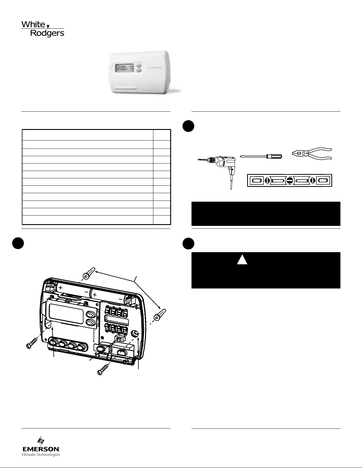
THERMOSTAT DETAILS
2
Screw anchors
PREPARATIONS
1
Assemble tools required as shown below.
FLAT BLADE SCREWDRIVER
HAND OR POWER
DRILL WITH 3/16 INCH
DRILL BIT, IF NEEDED
SPIRIT LEVEL OR PLUMB BOB AND LINE (OPTIONAL)
Failure to follow and read all instructions carefully
before installing or operating this control could cause
personal injury and/or property damage.
REMOVING OLD THERMOSTAT
3
CAUTION
!
To prevent electrical shock and/or equipment damage,
disconnect electrical power to the system at the main
fuse or circuit breaker until installation is complete.
WIRE CUTTER/STRIPPER
Mounting
holes
Electric/Gas
switch
Figure 1. Thermostat base
Mounting
holes
Before removing wires from old thermostat’s switching subbase,
label each wire with the terminal designation it was removed from.
1. Remove Old Thermostat: A standard heat/cool thermostat
consists of three basic parts:
a. The cover, which may be either a snap-on or hinge type.
b. The base, which is removed by loosening all captive screws.
c. The switching subbase, which is removed by unscrewing
the mounting screws that hold it on the wall or adaptor plate.
2. Shut off electricity at the main fuse box until installation is
complete. Ensure that electrical power is disconnected.
3. Remove the front cover of the old thermostat. With wires still
attached, remove wall plate from the wall. If the old thermostat
has a wall mounting plate, remove the thermostat and the wall
mounting plate as an assembly.
4. Identify each wire attached to the old thermostat using the
labels enclosed with the new thermostat.
5. Disconnect the wires from the old thermostat one at a time. DO
NOT LET WIRES FALL BACK INTO THE WALL.
6. Install new thermostat using the following procedures.
White-Rodgers is a division
of Emerson Electric Co.
www.white-rodgers.com
PART NO. 37-6295B
Replaces 37-6295A
0514
REMOVING OLD THERMOSTAT
TERMINAL CROSS REFERENCE CHART
New Thermostat
Terminal Designation
Other Manufacturers’
Terminal Designation
RH
RC
G
W
Y
4
R
G
W
Y
RH
R
G
W
Y
M
V
F
H
C
R5
-
G
4
Y6
R
-
G
W
Y
**
* These are four-wire, single-transformer systems.
Factory installed jumper wire between the RH
and RC terminals must remain in place.
3
CONTINUED FROM FIRST PAGE
ATTENTION! This product does not contain mercury. However, this product may replace a unit which contains mercury.
Do not open mercury cells. If a cell becomes damaged, do not
touch any spilled mercury. Wearing non-absorbent gloves, take
up the spilled mercury and place into a container which can be
sealed. If a cell becomes damaged, the unit should be discarded.
Mercury must not be discarded in household trash. When the unit
this product is replacing is to be discarded, place in a suitable
container and return to White-Rodgers for proper disposal.
MOUNTING AND WIRING
4
WARNING
!
Do not use on circuits exceeding specified voltage.
Higher voltage will damage control and could cause
shock or fire hazard.
Do not short out terminals on gas valve or primary
control to test. Short or incorrect wiring will damage
thermostat and could cause personal injury and/or
property damage.
Thermostat installation and all components of the system shall conform to Class II circuits per the NEC code.
Electric Heat or Single Stage
Heat Pump Systems
This thermostat is configured from the factory to operate a heat/
cool, fossil fuel (gas, oil, etc.), forced air system. It is configured
correctly for any system that DOES NOT require the thermostat
to energize the fan on a call for heat. If your system is an electric
or heat-pump system that REQUIRES the thermostat to turn on
the fan on a call for heat, locate the GAS/ELECTRIC switch (see
fig. 1) and switch it to the ELECTRIC position. This will allow the
thermostat to energize the fan immediately on a call for heat. If you
are unsure if the heating/cooling system requires the thermostat
to control the fan, contact a qualified heating and air conditioning
service person.
Hydronic (Hot Water or Steam)
Heating Systems
This thermostat is set to operate properly with a forced-air heating
system. If you have a hydronic heating system (a system that
heats with hot water or steam), you must set the thermostat to
operate properly with your system. Change the second option in
the configuration menu to SL (see CONFIGURATION MENU,
page 5).
CAUTION
!
Take care when securing and routing wires so they do
not short to adjacent terminals or rear of thermostat.
Personal injury and/or property damage may occur.
Attach Thermostat Base to Wall
1. Remove the packing material from the thermostat. Gently pull
the cover straight off the base. Forcing or prying on the
thermostat will cause damage to the unit. If necessary, move
the electric heat switch (see ELECTRIC HEAT SYSTEMS,
above).
2. Connect wires beneath terminal screws on base using appropriate wiring schematic (see figs. 2 through 7).
3. Place base over hole in wall and mark mounting hole locations
on wall using base as a template.
4. Move base out of the way. Drill mounting holes.
5. Fasten base loosely to wall, as shown in fig. 1, using two
mounting screws. Place a level against bottom of base, adjust
until level, and then tighten screws. (Leveling is for appearance only and will not affect thermostat operation.) If you are
using existing mounting holes, or if holes drilled are too large
and do not allow you to tighten base snugly, use plastic screw
anchors to secure base.
6. Push excess wire into wall and plug hole with a fire-resistant
material (such as fiberglass insulation) to prevent drafts from
affecting thermostat operation.
Battery Location
This thermostat requires 2 “AA” alkaline batteries to operate. If the
word LO BATTERY is displayed, the batteries are low and should
be replaced with fresh “AA” Energizer® alkaline batteries. To
replace the batteries, install the batteries along the top of the base
(see fig. 1). The batteries must be installed with the positive(+)
ends to the right.
www.white-rodgers.com
MOUNTING AND WIRING
RH
Y
24 VAC
120 VAC
Hot
Neutral
THERMOSTAT
SYSTEM
G W
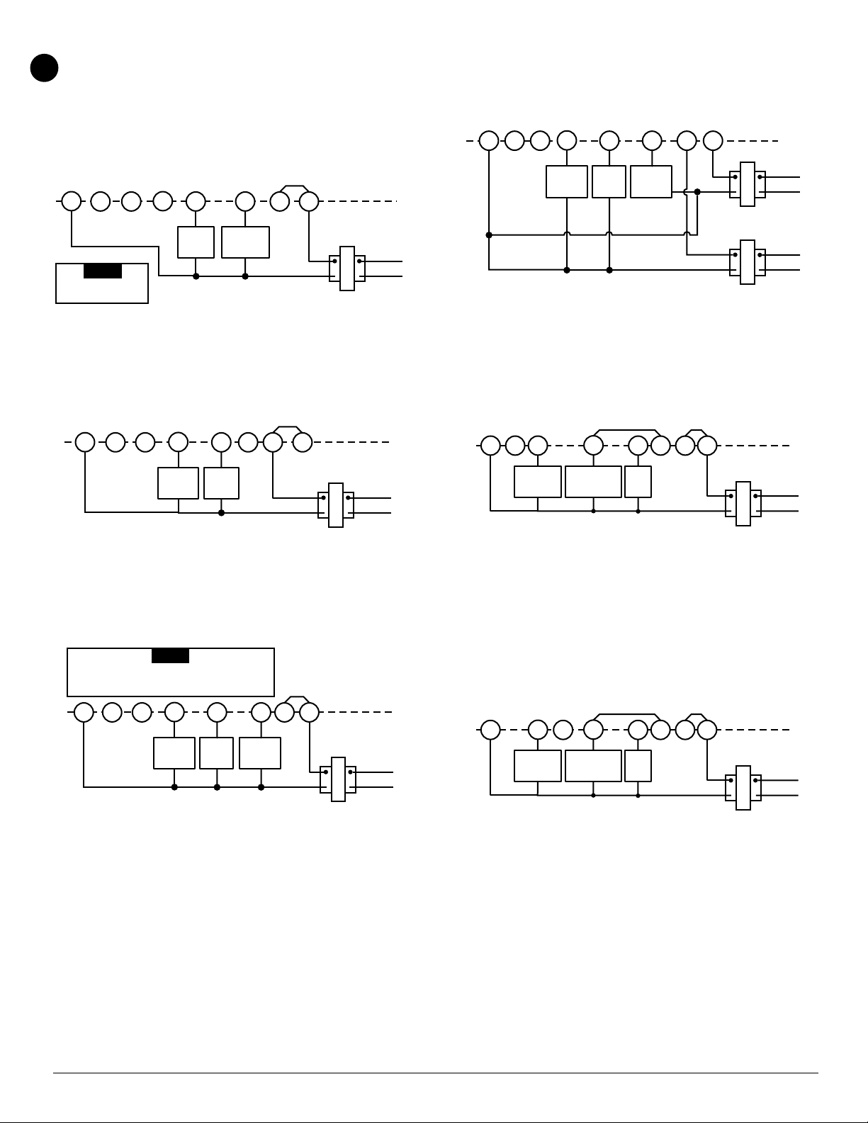
Figure 5. Typical wiring diagram for
heat/cool, 5-wire, two-transformer systems
HEATING
TRANSFORMER
Heating
System
Fan
Relay
Cooling
System
RC
24 VAC
120 VAC
Hot
Neutral
COOLING TRANSFORMER
OBC
‡
RH
Y
24 VAC
120 VAC
Hot
Neutral
THERMOSTAT
SYSTEM
G W
Figure 6. Typical wiring diagram for heat pump
with reversing valve energized in COOL
TRANSFORMER
Reversing
Valve*
RCOBC
‡
JUMPER
WIRE
Compressor
Contactor
JUMPER
WIRE
* Reversing valve is energized when the
system switch is in the COOL position
Fan
Relay
RH
Y
24 VAC
120 VAC
Hot
Neutral
THERMOSTAT
SYSTEM
G W
Figure 7. Typical wiring diagram for heat pump
with reversing valve energized in HEAT
TRANSFORMER
Reversing
Valve*
RCO
B
C
‡
JUMPER
WIRE
Compressor
Contactor
JUMPER
WIRE
* Reversing valve is energized when the
system switch is in the HEAT position
Fan
Relay
4
CONTINUED FROM SECOND PAGE
‡
NOTE
For 2-wire Heat only,
attach to RH and W
heat only, 3-wire, single transformer systems
‡
C
cool only, 3-wire, single transformer systems
YC
OB
G W
Fan
Relay
Heating
System
Figure 2. Typical wiring diagram for
Y
Cooling
System
G W
Fan
Relay
Figure 3. Typical wiring diagram for
JUMPER
RC
JUMPER
RCOB
WIRE
WIRE
24 VAC
THERMOSTAT
RH
SYSTEM
24 VAC
TRANSFORMER
THERMOSTAT
RH
SYSTEM
TRANSFORMER
Hot
120 VAC
Neutral
Hot
120 VAC
Neutral
RED jumper wire (provided with thermostat) must be
connected between thermostat RH and RC terminals
for proper thermostat operation with this system.
Y
OC‡B
Cooling
System
G W
Fan
Relay
Heating
System
Figure 4. Typical wiring diagram for
heat/cool, 4-wire, single transformer systems
NOTE
‡
The 24 Volt neutral connection to terminal C on the
thermostat is not required if the batteries are replaced
once a year with fresh “AA” Energizer® alkaline batteries.
JUMPER
WIRE
RH
RC
24 VAC
THERMOSTAT
SYSTEM
Hot
120 VAC
Neutral
TRANSFORMER
www.white-rodgers.com
 Loading...