

Emerson 510 Installation Manual
500 Series
510 Surge Protective Device
Installation, Operation and Maintenance Manual

EMERSON NETWORK POWER SURGE PROTECTIVE DEVICE
INSTALLATION, OPERATION AND MAINTENANCE MANUAL
TABLE OF CONTENTS
UNPACKING AND INSTALLATION
Unpacking and Preliminary Inspection ............................................................................. 2
Handling Considerations ................................................................................................. 2
Storage ............................................................................................................................... 2
LOCATION CONSIDERATIONS
Environment .................................................................................................................... 2
Audible Noise .................................................................................................................. 2
Service Clearances ........................................................................................................... 2
Mounting ........................................................................................................................ 2
Warnings Defined ............................................................................................................ 2
MODEL NUMBER CONFIGURATION
Model Number Configuration .......................................................................................... 3
Configuration & Voltage (Chart) ....................................................................................... 4
ELECTRICAL CONNECTIONS
Voltage Ratings and Power Source Configurations ........................................................... 5
Wire Connections ............................................................................................................ 5
Over Current Protection ................................................................................................... 5
NEC Considerations ......................................................................................................... 5
Voltage Protection Rating ....................................................................................................... 5
Circuit Ampacity Limitations ........................................................................................... 5
System Grounding and Bonding ...................................................................................... 5
Grounding Electrode ....................................................................................................... 6
Neutral Connection ......................................................................................................... 6
Parallel Connection / Wire Diagram ................................................................................. 6
INSTALLATION INSTRUCTIONS
Product Installation ......................................................................................................... 7
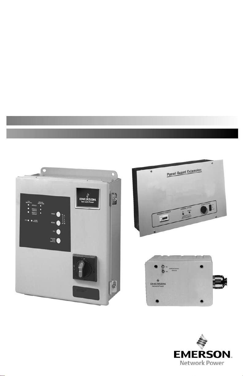
NEMA 12 Metal (Modular) Enclosure Option .................................................................... 8
NEMA 4X Non-Metallic (Non-Modular) Enclosure Option ................................................. 8
NEMA 1 Panelboard Extension (Modular) Enclosure Option ............................................. 9
MONITORING FEATURES
External Status Indicators (Standard) ............................................................................. 10
Audible Alarm (Standard/Optional) ................................................................................ 10
Summary Alarm Contact (Standard/Optional) ................................................................ 10
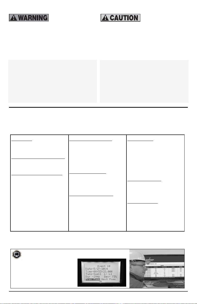
Transient Counter (Optional) ......................................................................................... 10
Advanced Transient Detection System (Optional) .......................................................... 10
TROUBLESHOOTING/SERVICING/MAINTENANCE
Troubleshooting ............................................................................................................ 10
Servicing......................................................................................................................
Corrective Maintenance ................................................................................................. 11
Preventative Maintenance ............................................................................................. 11
.. 10
Installation, Operation and Maintenance Manual IO-70103 Rev 2, 1/2015
1

UNPACKING AND INSTALLATION
Unpacking and Preliminary Inspection
1. Inspect the shipping crate(s) for damage or
signs of mishandling before unpacking the
unit.
2. Remove any securing bands and cardboard
packing and inspect the unit for any
obvious shipping damages.
3. If any damage as a result of shipping is
observed, immediately file a claim with the
shipping agency and forward a copy to your
local Emerson Network Power Surge
Protection Sales Representative.
Handling Considerations
Larger units are bolted to a shipping pallet to
facilitate handling by forklift or pallet jack.
Check the size and weight. Refer to the
cabinet data furnished with the unit.
Storage
The unit should be stored in a clean, dry
environment. Storage temperature range is 55ºC (-67ºF) to +85ºC (+185ºF). Care should
be taken to avoid condensation. All packing
and shipping materials should be left intact
until the unit is ready for final installation. If
the unit has been stored for an extended
period of time, the unit should be cleaned
and carefully inspected before placing into
service.
LOCATION CONSIDERATIONS
For optimum transient surge protection,
coordinated surge suppression should be
applied at the service entrance and all other
electrical connections to the building
(telephone, CATV, etc.), at known surge
generating loads within the building (large
motors, arc welders, switched capacitors,
etc.), as well as at sensitive electronic loads
(such as computers, electronic appliances,
solid state motor drives, etc.). For
interconnected electronic loads (such as by
way of data cabling), transient surge
suppression should also be applied to the
interconnecting wiring (data cables).
Installation, Operation and Maintenance Manual IO-70103 Rev 2, 1/2015
Environment — Unit is designed for
operation indoors in ambient temperatures
of -40ºC (-40ºF) to +60ºC (+140ºF) with a
relative humidity of 0% to 95% (noncondensing).
The unit is provided in an industrial use
enclosure, which is dust-tight and drip-tight
and should not be installed in areas with
excessive dust, corrosive vapors, flammable
materials or explosive atmospheres.
Audible Noise — The audible noise of the
unit is less than 40 dB at 5 feet, which allows
its placement within almost any room if
desired.
Service Clearances — Service clearance is
needed for units with hinged doors on the
front that are capable of being opened.
Thirty-six inches (36 in/914 mm) minimum is
recommended.
Mounting — Unit is intended to be wall
mounted. Refer to installation instructions for
mounting dimensions and weight.
Warnings Defined —
Danger: Indicate[s] a
hazardous situation which, if not avoided, will
result in death or serious injury. The signal
word "DANGER" is to be limited to the most
extreme situations. DANGER [signs] should
not be used for property damage hazards
unless personal injury risk appropriate to
these levels is also involved.
Danger:
Indique une situation dangereuse
qui, si elle n'est pas évitée, entraînera la mort
ou des blessures graves. Le mot comme
signal «DANGER» doit être limité aux
situations les plus extrêmes. Les signes
DANGER ne doivent pas être utilisés pour les
risques de dommages à la propriété, sauf si le
risque de blessures appropriées à ces niveaux
est également impliqué.
(continued)
2
(11)
(8)
(
hazardous situation which, if not avoided,
could result in death or serious injury.
WARNING [signs] should not be used for
property damage hazards unless personal
injury risk appropriate to this level is also
involved.
Avertissement:
dangereuse qui, si elle n'est pas évitée,
pourrait entraîner la mort ou des blessures
graves. Les signes AVERTISSEMENT ne
doivent pas être utilisés pour les risques de
dommages à la propriété, sauf si le risque de
blessures appropriées à ce niveau est
également impliqué.
Warning: Indicate[s] a
Indique une situation
Caution: Indicate[s] a
hazardous situation which, if not avoided,
could result in minor or moderate injury.
CAUTION [signs] without a safety alert
symbol may be used to alert against unsafe
practices that can result in property damage
only.
Attention:
Indique une situation dangereuse
qui, si elle n'est pas évitée, pourrait entraîner
des blessures mineures ou modérées. Les
signes ATTENTION sans symbole d'alerte de
sécurité peuvent être utilisés pour mettre en
garde contre des pratiques dangereuses qui
peuvent entraîner des dommages matériels
seulement.
MODEL NUMBER CONFIGURATION
Model #: _ _ _ _ _ _ _ _ _ _ _ _ _
1 2 3 4 5 6 7 8 9 10 11 12 13
1-3) Series
510 = Modular/Non-Modular
MOV
(4-5) Configuration & Voltage
See Chart on next page
(6-7) Surge Rating Per Mode
06 = 65kA
08 = 80kA
10 = 100kA
12 = 125kA
13 = 130kA
16 = 160kA
20 = 200kA
25 = 250kA
Modes of Protection
A = All Modes of Protection
B = L-N & N-G
E = L-L
F = L-N
G = L-G
(9) Connection Type
N = Wiring terminals/Lugs
R = Rotary Disconnect Switch
W = Wire Leads
(10) Monitoring Options
R = LED/Relay
A = LED/Alarm/Relay
C = LED/Alarm/Counter/Relay
T= Advanced Transient
Detection System
See manual “IO-70109
”
Units that include the ADVANCED TRANSIENT DETECTION SYSTEM monitoring option
Advanced Transient Detection System
Refer to manual IO-70109
for additional installation and
operation instructions.
Enclosure
R = Type 3R (metal)
G = Type 4 (metal)
H = Type 4X (Stainless Steel)
J = Type 4X (non-metallic)
L = Type 12 (metal)
F = Panelboard Flush (metal)
S = Panelboard Surface (metal)
(12) UL 1449 Type
0 = No UL
1 = Type 1
2 = Type 2
(13) Accessories
S = Standard
X = SPD with additional
Options/Accessories
Installation, Operation and Maintenance Manual IO-70103 Rev 2, 1/2015
3
 Loading...