

Page 1
Instruction Manual
IB-106-3081 Rev. 1.5
September 2002
Model 3081FG
Two-Wire In Situ
Oxygen Analyzer
(550° to 1600°C)
http://www.processanalytic.com
Page 2

ESSENTIAL INSTRUCTIONS
READ THIS PAGE BEFORE PROCEEDING!
Rosemount Analytical designs, manufactures and tests its products to meet many national and
international standards. Because these instruments are sophisticated technical products, you
MUST properly install, use, and maintain them to ensure they continue to operate within their
normal specifications. The following instructions MUST be adhered to and integrated into your
safety program when installing, using, and maintaining Rosemount Analytical products. Failure to
follow the proper instructions may cause any one of the following situations to occur: Loss of life;
personal injury; property damage; damage to this instrument; and warranty invalidation.
• Read all instructions prior to installing, operating, and servicing the product.
• If you do not understand any of the instructions, contact your Rosemount Analytical repre-
sentative for clarification.
• Follow all warnings, cautions, and instructions marked on and supplied with the product.
• Inform and educate your personnel in the proper installation, operation, and mainte-
nance of the product.
• Install your equipment as specified in the Installation Instructions of the appropriate In-
struction Manual and per applicable local and national codes. Connect all products to the
proper electrical and pressure sources.
• To ensure proper performance, use qualified personnel to install, operate, update, program,
and maintain the product.
• When replacement parts are required, ensure that qualified people use replacement parts
specified by Rosemount. Unauthorized parts and procedures can affect the product’s performance, place the safe operation of your process at risk, and VOID YOUR WARRANTY.
Look-alike substitutions may result in fire, electrical hazards, or improper operation.
• Ensure that all equipment doors are closed and protective covers are in place, except
when maintenance is being performed by qualified persons, to prevent electrical shock
and personal injury.
The information contained in this document is subject to change without notice.
Emerson Process Management
Rosemount Analytical Inc.
Process Analytic Division
1201 N. Main St.
Orrville, OH 44667-0901
T (330) 682-9010
F (330) 684-4434
e-mail: gas.csc@EmersonProcess.com
http://www.processanalytic.com
Page 3

HIGHLIGHTS OF CHANGES
Effective June, 1998 Rev. 1.0
Page Summary
Page 2-10 Corrected part numbers in Figure 2-9 for Flowmeter and Ref Air Set.
Page 3-4 Modified Figure 3-5 to reflect selection of additional faults.
Page 3-11 Modified paragraph 3-6a to select additional fault screens.
Page 4-4 Updated menus for O
Page 8-1 Added in replacement part numbers for Model 3081 Transmitter.
Effective April, 1999 Rev. 1.1
Page Summary
Cover Added “Model 3081FG” to manual title.
Page 1-2 Deleted 48 in. probe and Mullite probe options from Product Matrix.
Page 1-7 Deleted 48 in. probe and Mullite probe references from specifications.
Page 2-1 through 2-6 Changed probe installation mounting and insertion procedures and
requirements.
Page 5-1 Revised PC board stack replacement procedure.
Throughout Changed all references to “power supply board” to read “analog board”.
Reformatted document in accordance with the latest style guide.
Effective October, 2000 Rev. 1.2
Page Summary
Throughout Changed all references of 38 in. (965 mm) probe to 34.625 in.
(880 mm).
value, SV, TV, and 4V values.
2
Effective April, 2001 Rev. 1.3
Page Summary
Page 2-9 Added 1st WARNING to paragraph 2-3.
Page 10-2 Added drawing 1400184.
Effective January, 2002 Rev. 1.4
Page Summary
Page 8-1 Added part number for PC Board Stack Assembly.
Effective September, 2002 Rev. 1.5
Page Summary
Page 1-7 Updated process temperature limits specification.
Page 4

Page 5

Model 3081FG
PREFACE........................................................................................................................ P-1
Definitions ........................................................................................................................P-1
Safety Instructions .......................................................................................................... P-2
1-0 DESCRIPTION AND SPECIFICATIONS........................................................................ 1-1
1-1 Component Checklist Of Typical System (Package Contents) .................................. 1-1
1-2 System Overview............................................................................................................ 1-3
1-3 Specifications................................................................................................................... 1-7
2-0 INSTALLATION .............................................................................................................. 2-1
2-1 Pre-Installation................................................................................................................. 2-1
2-2 Mechanical Installation ................................................................................................... 2-1
2-3 Electrical Installation....................................................................................................... 2-9
2-4 Pneumatic Installation .................................................................................................. 2-11
3-0 STARTUP AND OPERATION ...................................................................................... 3-1
3-1 General ............................................................................................................................ 3-1
3-2 Power Up........................................................................................................................ 3-1
3-3 Reestablishing Proper Calibration Check Gas Flow Rate......................................... 3-2
3-4 Operation ......................................................................................................................... 3-3
3-5 Program Menu ................................................................................................................3-6
3-6 Diagnostics Menu ......................................................................................................... 3-11
3-7 CALCHECK MENU ...................................................................................................... 3-13
Instruction Manual
IB-106-3081 Rev. 1.5
September 2002
TABLE OF CONTENTS
4-0 HART/AMS...................................................................................................................... 4-1
4-1 Overview.......................................................................................................................... 4-1
4-2 HART Communicator Signal Line Connections ........................................................... 4-1
4-3 HART Communicator PC Connections ........................................................................ 4-3
4-4 Off-Line and On-Line Operations ................................................................................. 4-3
4-5 Menu Tree for HART Communicator/
Two-Wire In Situ Oxygen Analyzer Applications...................................................... 4-3
4-6 HART Communicator Start CALCHECK Method ........................................................ 4-7
5-0 MAINTENANCE AND SERVICE .................................................................................. 5-1
5-1 Model 3081 Electronics Replacement ......................................................................... 5-1
5-2 Oxygen Probe Replacement ......................................................................................... 5-3
6-0 TROUBLESHOOTING .................................................................................................... 6-1
6-1 General ............................................................................................................................ 6-1
6-2 Probe Life ....................................................................................................................... 6-1
6-3 Fault Indications.............................................................................................................. 6-2
6-4 Identifying and Correcting Fault Indications ................................................................. 6-3
7-0 RETURN OF MATERIAL .............................................................................................. 7-1
8-0 REPLACEMENT PARTS ............................................................................................... 8-1
9-0 INDEX.............................................................................................................................. 9-1
10-0 DRAWINGS AND SCHEMATICS ............................................................................... 10-1
Rosemount Analytical Inc. A Division of Emerson Process Management i
Page 6

Instruction Manual
IB-106-3081 Rev. 1.5
September 2002
Figure 1-1. Typical System Package ....................................................................................... 1-1
Figure 1-2. Two-Wire In Situ Oxygen Analyzer HART Connections and AMS Application ..... 1-5
Figure 1-3. Typical System Installation .................................................................................... 1-6
Figure 1-4. Power Supply and Load Requirements ................................................................. 1-8
Figure 2-1. Probe Installation Details ....................................................................................... 2-2
Figure 2-2. Optional Adapter Plate........................................................................................... 2-3
Figure 2-3. Optional Probe Mounting Flange ........................................................................... 2-3
Figure 2-4. Horizontal Probe Installation .................................................................................. 2-4
Figure 2-5. Adjusting Probe Insertion Depth ............................................................................ 2-5
Figure 2-6. Flat Surface Mounting Dimensional Information.................................................... 2-7
Figure 2-7. Pipe Mounting Dimensional Information ................................................................ 2-8
Figure 2-8. Display Positioning Assembly................................................................................ 2-9
Figure 2-9. Oxygen Probe Terminal Block ............................................................................. 2-10
Figure 2-10. Model 3081 Transmitter Terminal Block .............................................................. 2-11
Figure 2-11. Oxygen Probe Gas Connections ......................................................................... 2-11
Figure 2-12. Air Set, Plant Air Connection ............................................................................... 2-12
Figure 3-1. Normal Operation Display...................................................................................... 3-1
Figure 3-2. Faulted Operation Display ..................................................................................... 3-1
Figure 3-3. Proper Calibration Check Gas Flow Rate.............................................................. 3-2
Figure 3-4. Normal Operation Display...................................................................................... 3-3
Figure 3-5. Model 3081 Transmitter Menu Tree ...................................................................... 3-4
Figure 3-6. Infrared Remote Control (IRC)............................................................................... 3-5
Figure 3-7. CODE..................................................................................................................... 3-6
Figure 3-8. DISPLAY CODE ................................................................................................... 3-6
Figure 3-9. FAULT VAL........................................................................................................... 3-7
Figure 3-10. UPPER RANGE VAL ........................................................................................... 3-7
Figure 3-11. CELL T HI ............................................................................................................ 3-7
Figure 3-12. RESET MAX CELL T ........................................................................................... 3-8
Figure 3-13. SET O
Figure 3-14. TRIM 4 mA?........................................................................................................... 3-8
Figure 3-15. TRIM 20 mA?......................................................................................................... 3-9
Figure 3-16. SET HI BOTTLE O
Figure 3-17. SET LO BOTTLE O
Figure 3-18. SET O
Figure 3-19. SET CODE.......................................................................................................... 3-10
Figure 3-20. SHOW FAULT .................................................................................................... 3-11
Figure 3-21. T/C mV................................................................................................................. 3-11
Figure 3-22. O
Figure 3-23. CELL IMPEDANCE............................................................................................. 3-12
Figure 3-24. PREVIOUS SLOPE ............................................................................................ 3-12
Figure 3-25. PREVIOUS CONSTANT .................................................................................... 3-12
Figure 3-26. MAX CELL T ......................................................................................................3-13
Figure 3-27. IN MANUAL? ...................................................................................................... 3-14
Figure 3-28. ACCEPT HIGH O
Figure 3-29. ACCEPT LOW O
Figure 3-30. SLOPE ................................................................................................................. 3-15
Figure 3-31. CONSTANT ......................................................................................................... 3-15
Figure 4-1. Signal Line Connections, > 250 Ohms Lead Resistance ...................................... 4-2
Figure 4-2. Signal Line Connections, < 250 Ohms Lead Resistance ...................................... 4-3
Model 3081FG
LIST OF ILLUSTRATIONS
FILTER TIME.......................................................................................... 3-8
2
............................................................................................. 3-9
2
............................................................................................ 3-9
TRACKING ............................................................................................ 3-10
2
CELL mV ....................................................................................................... 3-11
2
2
.............................................................................................. 3-14
2
............................................................................................... 3-15
2
ii Rosemount Analytical Inc. A Division of Emerson Process Management
Page 7

Model 3081FG
Figure 4-3. Menu Tree for HART/AMS on the Two-Wire In Situ
Oxygen Analyzer (Sheet 1 of 3)............................................................................. 4-4
Figure 5-1. Two-Wire In Situ Oxygen Analyzer Exploded View............................................... 5-2
Figure 5-2. Oxygen Probe Terminal Block ............................................................................... 5-4
Figure 6-1. Slope vs. Impedance ............................................................................................. 6-1
Figure 6-2. Speed of Response ............................................................................................... 6-2
Figure 6-3. Faulted Operation Display ..................................................................................... 6-2
Figure 6-4. Model 3081 Transmitter Terminal Block................................................................ 6-3
Figure 6-5. Fault 1, Open Thermocouple ................................................................................. 6-4
Figure 6-6. Fault 2, Reversed Thermocouple .......................................................................... 6-4
Figure 6-7. Fault 3, Shorted Thermocouple ............................................................................. 6-5
Figure 6-8. Fault 4, High Probe Temperature .......................................................................... 6-5
Figure 6-9. Fault 5, O
Figure 6-10. Fault 6, Cell Impedance Too High ......................................................................... 6-6
Figure 6-11. Fault 7, Reversed O
Instruction Manual
IB-106-3081 Rev. 1.5
September 2002
Cell Open............................................................................................. 6-6
2
Cell ...................................................................................... 6-7
2
LIST OF TABLES
Table 1-1. Product Matrix........................................................................................................ 1-2
Table 3-1. Model 3081 Transmitter Parameters ................................................................... 3-10
Table 8-1. Replacement Parts List.......................................................................................... 8-1
Rosemount Analytical Inc. A Division of Emerson Process Management iii
Page 8

Instruction Manual
IB-106-3081 Rev. 1.5
September 2002
Model 3081FG
iv Rosemount Analytical Inc. A Division of Emerson Process Management
Page 9
Model 3081FG
The purpose of this manual is to provide information concerning the components, functions, installation and maintenance of the Model 3081FG Two-Wire In Situ Oxygen Analyzer (550° to 1600°C).
Some sections may describe equipment not used in your configuration. The user should
become thoroughly familiar with the operation of this module before operating it. Read
this instruction manual completely.
The following definitions apply to WARNINGS, CAUTIONS, and NOTES found throughout this
publication.
Instruction Manual
IB-106-3081 Rev. 1.5
September 2002
PREFACE
DEFINITIONS
Highlights an operation or maintenance
procedure, practice, condition, statement, etc. If not strictly observed, could
result in injury, death, or long-term
health hazards of personnel.
Highlights an essential operating procedure,
condition, or statement.
: EARTH (GROUND) TERMINAL
: PROTECTIVE CONDUCTOR TERMINAL
: RISK OF ELECTRICAL SHOCK
: WARNING: REFER TO INSTRUCTION BULLETIN
NOTE TO USERS
Highlights an operation or maintenance
procedure, practice, condition, statement, etc. If not strictly observed, could
result in damage to or destruction of
equipment, or loss of effectiveness.
NOTE
The number in the lower right corner of each illustration in this publication is a manual illustration number. It is not a part number, and is not related to the illustration in any technical
manner.
Rosemount Analytical Inc. A Division of Emerson Process Management P-1
Page 10

Instruction Manual
IB-106-3081 Rev. 1.5
September 2002
FOR THE WIRING AND INSTALLATION
The following safety instructions apply specifically to all EU member states. They should
be strictly adhered to in order to assure compliance with the Low Voltage Directive. NonEU states should also comply with the following unless superseded by local or National
Standards.
1. Adequate earth connections should be made to all earthing points, internal and external,
where provided.
2. After installation or troubleshooting, all safety covers and safety grounds must be replaced.
The integrity of all earth terminals must be maintained at all times.
3. Mains supply cords should comply with the requirements of IEC227 or IEC245.
Model 3081FG
IMPORTANT
SAFETY INSTRUCTIONS
OF THIS APPARATUS
4. All wiring shall be suitable for use in an ambient temperature of greater than 75°C.
5. All cable glands used should be of such internal dimensions as to provide adequate cable
anchorage.
6. To ensure safe operation of this equipment, connection to the mains supply should only be
made through a circuit breaker which will disconnect all circuits carrying conductors during a
fault situation. The circuit breaker may also include a mechanically operated isolating switch.
If not, then another means of disconnecting the equipment from the supply must be provided
and clearly marked as such. Circuit breakers or switches must comply with a recognized
standard such as IEC947. All wiring must conform with any local standards.
7. Where equipment or covers are marked with the symbol to the right, hazardous voltages are likely to be present beneath. These covers should only be
removed when power is removed from the equipment — and then only by
trained service personnel.
8. Where equipment or covers are marked with the symbol to the right, there is a
danger from hot surfaces beneath. These covers should only be removed by
trained service personnel when power is removed from the equipment. Certain surfaces may remain hot to the touch.
9. Where equipment or covers are marked with the symbol to the right, refer to
the Operator Manual for instructions.
10. All graphical symbols used in this product are from one or more of the following standards: EN61010-1, IEC417, and ISO3864.
P-2 Rosemount Analytical Inc. A Division of Emerson Process Management
Page 11
Model 3081FG
1
DESCRIPTION AND SPECIFICATIONS
Instruction Manual
IB-106-3081 Rev. 1.5
September 2002
SECTION 1
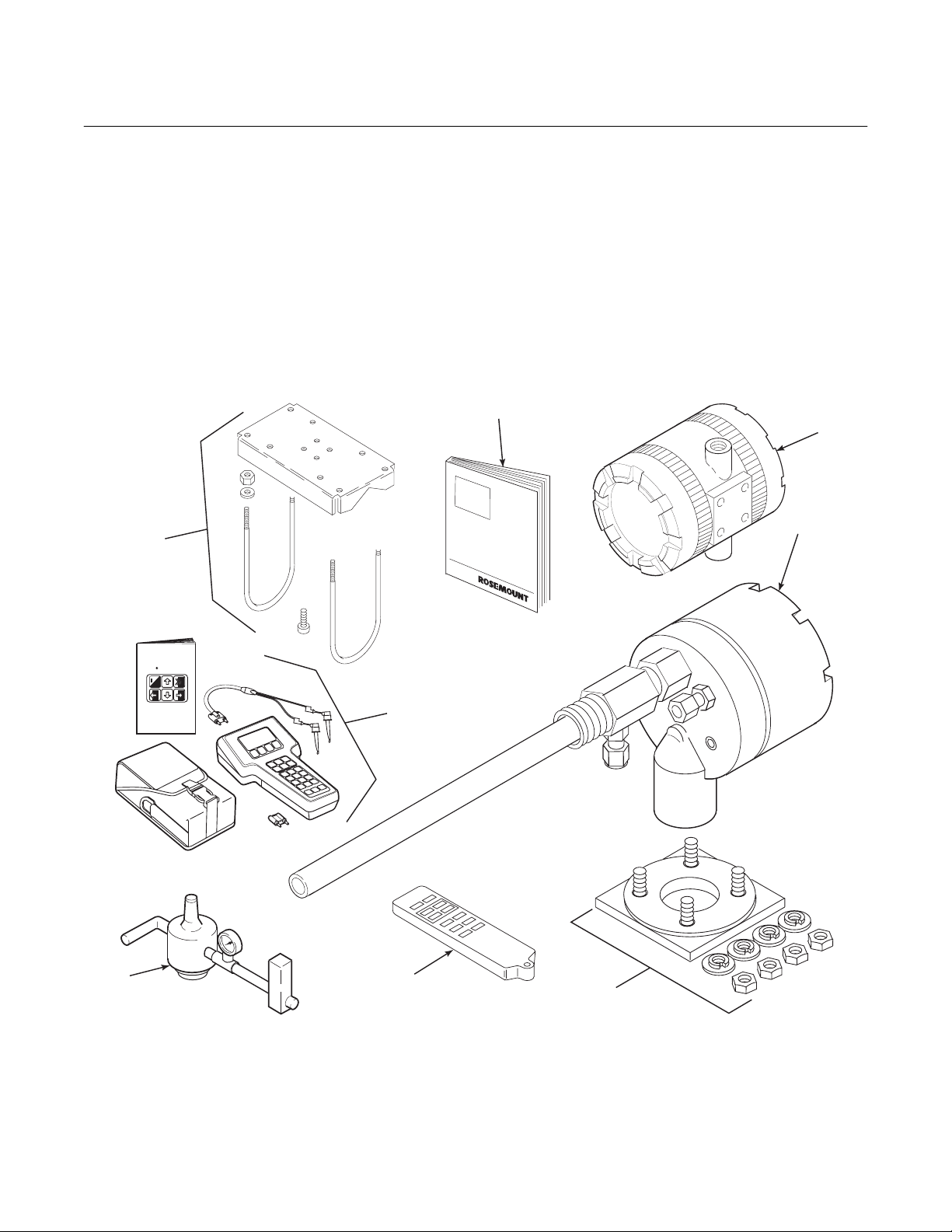
1-1 COMPONENT CHECKLIST OF TYPICAL
SYSTEM (PACKAGE CONTENTS)
A typical Rosemount Two-Wire In Situ Oxygen
Analyzer should contain the items shown in
Figure 1-1. Record the part number, serial number, and order number for each component of
your system in the table located on the first
8
MAN4275A00
English
October1994
HART Communicator
o
page of this manual. Also, use the product matrix in Table 1-1 to compare your order number
against your unit. The first part of the matrix defines the model. The last part defines the various options and features of the analyzer.
Ensure the features and options specified by
your order number are on or included with the
unit.
1
2
3
TM
FISHER-ROSEMOUNT
6
1. Instruction Bulletin
2. Model 3081 Transmitter
3. Oxygen Probe
4. Adapter Plate with mounting hardware
and gasket (Optional)
Figure 1-1. Typical System Package
7
5
4
5. Infrared Remote Control (IRC) (Optional)
6. Reference Air Set (Optional)
7. HART
®
Communicator Package (Optional)
8. Pipe Mounting Kit (Optional)
26020036
Rosemount Analytical Inc. A Division of Emerson Process Management Description and Specifications 1-1
Page 12

Instruction Manual
IB-106-3081 Rev. 1.5
September 2002
Table 1-1. Product Matrix
3081FG High Temperature Oxygen Flue Gas Analyzer
High Temperature Analyzer - Instruction Book
Code Sensing Probe Length
1 20 in. (508 mm) probe, 1/4 in. tube fittings
2 26 in. (660 mm) probe, 1/4 in. tube fittings
3 34.625 in. (880 mm) probe, 1/4 in. tube fittings
Code Probe Outer Tube Material - Maximum Operating Temperature
1 Alumina - 2912°F (1600°C) maximum - 1.25 NPT mounting
2 Inconel 600 - 1832°F (1000°C) maximum - 1.25 NPT mounting
Code Mounting Adapter - Stack Side
0 No adapter plate required uses 1.25 NPT
("0" must also be chosen under "Mounting Adapter" below)
1 New flanged installation - Square weld plate with studs (matches "Mounting Adapter" below)
2 Model 450 mounting ("4" must also be chosen under "Mounting Adapter" below)
3 Competitor's Mount ("5" must also be chosen under "Mounting Adapter" below)
Code Mounting Adapter - Probe Side
0 No adapter plate
1 ANSI 2 in. 150 lb flange to 1.25 NPT adapter
(6 in. dia. flange, 4.75 in. BC with 4 x 0.75 in. dia. holes)
2 DIN to 1.25 NPT adapter (184 mm flange, 145 mm BC with 4 x 18 mm dia. holes)
3 JIS to 1.25 NPT adapter (155 mm flange, 130 mm BC with 4 x 13 mm dia. holes)
4 Model 450 to 1.25 NPT adapter
5 Competitor's mounting flange
Code Electronics & Housing - Intrinsically Safe, NEMA 4X, IP65
1 3081 Electronics (Hart-compatible) - CENELEC EEx ia IIC T5
2 3081 Electronics (Hart-compatible) - CSA pending
3 3081 Electronics (Hart-compatible) - FM Class I, Div. I, Groups B,C,D
Code Housing Mounting
0 Surface or wall mounting
1 1/2 to 2 in. pipe mounting
Code Communications
0 No remote control
1 Infrared Remote Control (IRC)
(LCD display through cover window)
Code Calibration Accessories
1 No hardware
2 Calibration and reference air flowmeters and refer-
ence air pressure regulator
Code Armored Cable Length
00 No cable
11 20 ft (6 m)
12 40 ft (12 m)
13 60 ft (18 m)
14 80 ft (24 m)
15 100 ft (30 m)
16 150 ft (45 m)
17 200 ft (61 m)
18 300 ft (91 m)
19 400 ft (122 m)
20 500 ft (152 m)
3081FG2100111211 Example
Model 3081FG
1-2 Description and Specifications Rosemount Analytical Inc. A Division of Emerson Process Management
Page 13

Model 3081FG
1
Instruction Manual
IB-106-3081 Rev. 1.5
September 2002
1-2 SYSTEM OVERVIEW
a. Scope
This Instruction Bulletin is designed to supply details needed to install, start up, operate, and maintain the Rosemount Two-Wire
In Situ Oxygen Analyzer. The analyzer consists of an oxygen probe and Model 3081
Transmitter. The signal conditioning electronics of the Model 3081 Transmitter outputs a 4-20 mA signal representing an O
value. An infrared remote control (IRC) allows access to setup, calibration, and diagnostics. This same information, plus
additional details, can be accessed with the
HART Model 275 handheld communicator
or Asset Management Solutions (AMS)
software.
b. System Description
The Rosemount Two-Wire In Situ Oxygen
Analyzer is designed to measure the net
concentration of oxygen in an industrial process; i.e., the oxygen remaining after all fuels have been oxidized. The oxygen probe
is permanently positioned within an exhaust
duct or stack and performs its task without
the use of a sampling system. The Model
3081 Transmitter is mounted remotely and
conditions the oxygen probe outputs.
The equipment measures oxygen percentage by reading the voltage developed
across an electrochemical cell, which consists of a small yttria-stabilized, zirconia
disc. Both sides of the disc are coated with
porous metal electrodes. The millivolt output
voltage of the cell is given by the following
Nernst equation:
EMF = KT log10(P1/P2) + C
Where:
1. P
is the partial pressure of the oxygen
2
in the measured gas on one side of the
cell.
2. P
is the partial pressure of the oxygen
1
in the reference air on the opposite side
of the cell.
3. T is the absolute temperature.
4. C is the cell constant.
5. K is an arithmetic constant.
NOTE
For best results, use clean, dry, instrument air (20.95% oxygen) as the
reference air.
NOTE
The probe uses a Type B thermocouple to measure the cell temperature.
When the cell is at 550°C to 1600°C
2
(1022°F to 2912°F) and there are unequal
oxygen concentrations across the cell, oxygen ions will travel from the high oxygen
partial pressure side to the low oxygen partial pressure side of the cell. The resulting
logarithmic output voltage is approximately
50 mV per decade.
The output is proportional to the inverse
logarithm of the oxygen concentration.
Therefore, the output signal increases as
the oxygen concentration of the sample gas
decreases. This characteristic enables the
Rosemount Two-Wire In Situ Oxygen Analyzer to provide exceptional sensitivity and
accuracy at low oxygen concentrations.
Oxygen analyzer equipment measures net
oxygen concentration in the presence of all
the products of combustion, including water
vapor. Therefore, it may be considered an
analysis on a "wet" basis. In comparison
with older methods, such as the portable
apparatus, which provides an analysis on a
"dry" gas basis, the "wet" analysis will, in
general, indicate a lower percentage of oxygen. The difference will be proportional to
the water content of the sampled gas
stream.
c. System Configuration
The equipment discussed in this manual
consists of two major components: the oxygen probe and the Model 3081 Transmitter.
Oxygen probes are available in three length
options, providing in situ penetration appropriate to the size of the stack or duct. The
options on length are 20 in. (508 mm), 26 in.
(660 mm), or 34.625 in. (880 mm).
Rosemount Analytical Inc. A Division of Emerson Process Management Description and Specifications 1-3
Page 14

Instruction Manual
IB-106-3081 Rev. 1.5
September 2002
Model 3081FG
The Model 3081 Transmitter is a two-wire
transmitter providing an isolated output, 420 mA, that is proportional to the measured
oxygen concentration. A customer-supplied
24 VDC power source is required to simultaneously provide power to the electronics
and a 4-20 mA signal loop. The transmitter
accepts millivolt signals generated by the
probe and produces the outputs to be used
by other remotely connected devices. The
output is an isolated 4-20 mA linearized
current.
d. System Features
1. The cell output voltage and sensitivity
increase as the oxygen concentration
decreases.
2. High process temperatures eliminate
the need for external cell heating and
increase cell accuracy.
3. HART communication is standard. To
use the HART capability, you must
have either:
(a) HART Model 275 Communicator
(b) Asset Management Solutions
(AMS) software for the PC
(a) Infrared Remote Control. The IRC
allows access to fault indication
menus on the Model 3081 Transmitter LCD display. Calibration can
be performed from the IRC keypad.
(b) Optional HART Interface. The
Two-Wire In Situ Oxygen Analyzer’s 4-20 mA output line transmits an analog signal proportional
to the oxygen level. The HART
output is superimposed on the 4-20
mA output line. This information
can be accessed through the
following:
1 Rosemount Model 275 Hand-
held Communicator - The
handheld communicator requires Device Description
(DD) software specific to the
Two-Wire In Situ Oxygen
Analyzer. The DD software
will be supplied with many
Model 275 units but can also
be programmed into existing
units at most FisherRosemount service offices.
See Section 4, HART/AMS,
for additional HART
information.
4. Easy probe replacement due to the
light-weight, compact probe design.
5. Remote location of the Model 3081
Transmitter removes the electronics
from high temperature or corrosive
environments.
6. Power is supplied to the electronics
through the 4-20 mA line for intrinsic
safety (IS) purposes.
7. Infrared remote control (IRC) allows
interfacing without exposing the
electronics.
8. An operator can operate and diagnostically troubleshoot the Two-Wire In
Situ Oxygen Analyzer in one of two
ways:
1-4 Description and Specifications Rosemount Analytical Inc. A Division of Emerson Process Management
9. Selected Distributed Control Systems -
10. A calibration check procedure is pro-
2 Personal Computer (PC) -
The use of a personal computer requires AMS software
available from FisherRosemount.
The use of distributed control systems
requires input/output (I/O) hardware
and AMS Security codes are provided
to (by infrared remote control) prevent
unintended changes to analyzers adjacent to the one being accessed.
vided to determine if the Rosemount
Two-Wire In Situ Oxygen Analyzer is
correctly measuring the net oxygen
concentration in the industrial process.
Page 15
Model 3081FG
1
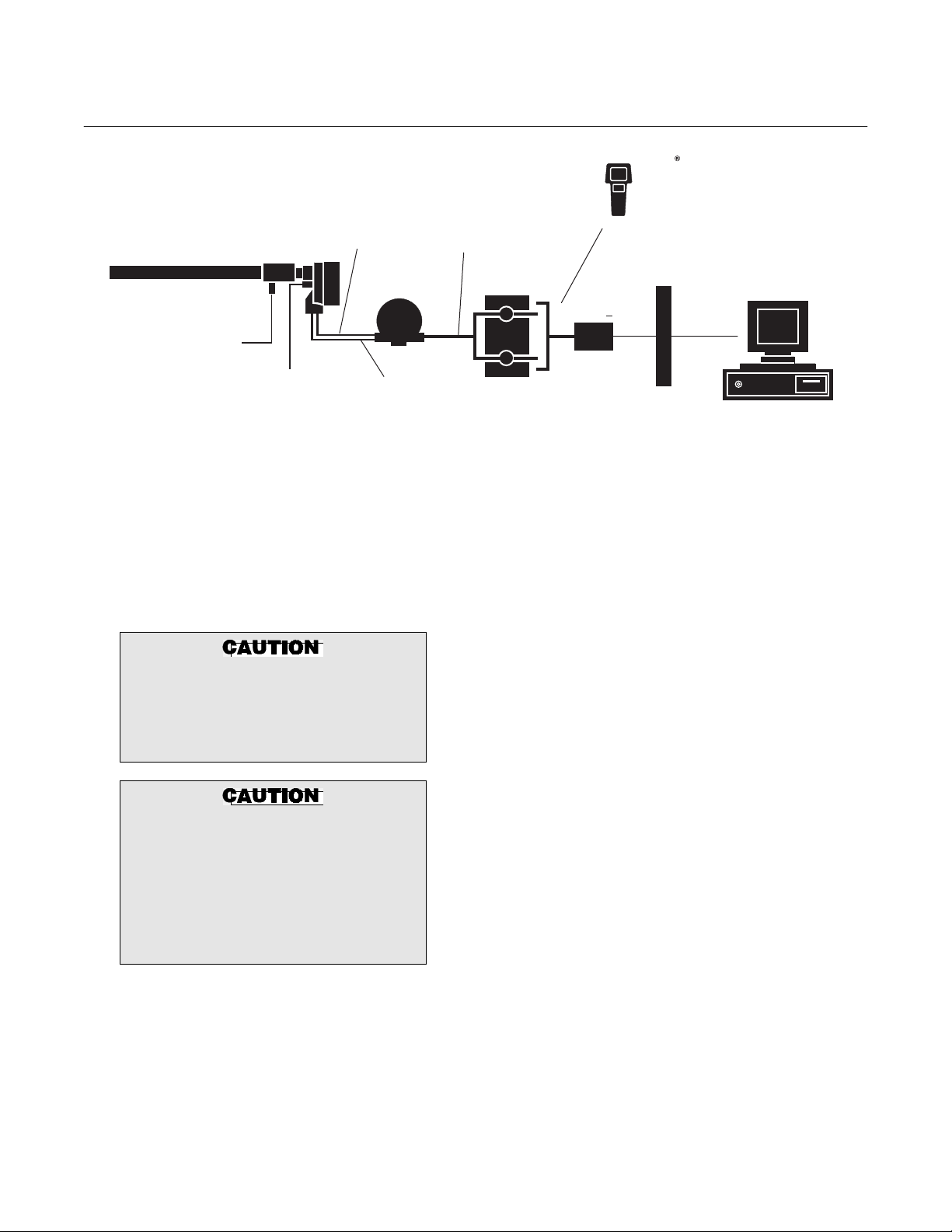
TWO-WIRE IN SITU
OXYGEN ANALYZER
CALIBRATION CHECK
GAS LINE
REFERENCE
Figure 1-2. Two-Wire In Situ Oxygen Analyzer HART Connections and AMS Application
AIR LINE
OmV
2
SIGNAL
MODEL 3081
TRANSMITTER
TEMPERATURE
mV SIGNAL
4-20 mA OUTPUT
(TWISTED PAIR)
TERMINATION IN
CONTROL ROOM
+
24 VDC
POWER
SUPPLY
Instruction Manual
HART MODEL 275
HAND HELD
INTERFACE
INTRINSIC
SAFETY
BARRIER
(OPTIONAL)
ASSET MANAGEMENT
IB-106-3081 Rev. 1.5
September 2002
SOLUTIONS
26020037
e. Handling the Analyzer
The probe was specially packaged to prevent breakage due to handling. Do not remove the padding material from the probe
until immediately before installation.
It is important that printed circuit
boards and integrated circuits are
handled only when adequate antistatic
precautions have been taken to prevent possible equipment damage.
The oxygen probe is designed for industrial applications. Treat with care to
avoid physical damage. The probe
contains components made from ceramic, which are susceptible to shock
when mishandled. THE WARRANTY
DOES NOT COVER DAMAGE FROM
MISHANDLING.
f. System Considerations
Prior to installing your Rosemount Two-Wire
In Situ Oxygen Analyzer, make sure you
have all the components necessary to make
the system installation. Ensure all the components are properly integrated to make the
system functional.
After verifying that you have all the components, select mounting locations and determine how each component will be placed in
terms of available line voltage, ambient
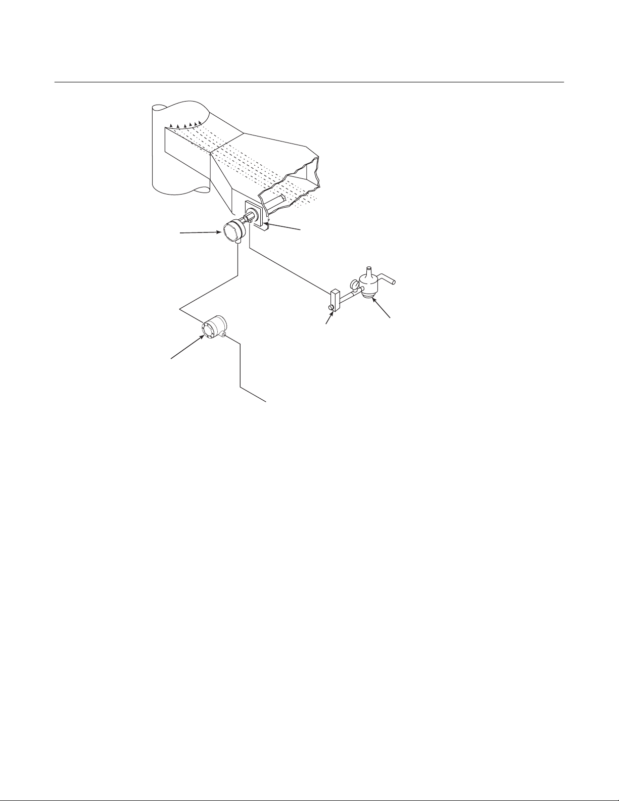
temperatures, environmental considerations, convenience, and serviceability. Figure 1-2 shows a typical system wiring. A
typical system installation is illustrated in
Figure 1-3.
Rosemount Analytical Inc. A Division of Emerson Process Management Description and Specifications 1-5
Page 16
Instruction Manual
IB-106-3081 Rev. 1.5
September 2002
Model 3081FG
GASES
DUCT
STACK
OXYGEN
PROBE
MODEL 3081
TRANSMITTER
4-20 mA SIGNAL
Figure 1-3. Typical System Installation
A source of instrument air is required at the
oxygen probe for reference air use. Since
the Two-Wire In Situ Oxygen Analyzer is
equipped with an in-place calibration feature, provisions should be made for connecting calibration check gas tanks to the
oxygen probe during calibration.
If the calibration check gas bottles are to be
permanently connected, a check valve is
required next to the calibration fittings on
the integral electronics.
This check valve is to prevent breathing of
calibration check gas line and subsequent
flue gas condensation and corrosion. The
OPTIONAL
ADAPTER
PLATE
FLOWMETER
INSTRUMENT
AIR SUPPLY
(REFERENCE AIR)
PRESSURE
REGULATOR
26020038
check valve is in addition to the stop valve
in the calibration check gas kit.
NOTE
The electronics of the Model 3081
Transmitter is rated NEMA 4X (IP65)
and is capable of operating at temperatures up to 65°C (149°F).
Retain the packaging in which the
Rosemount Two-Wire In Situ Oxygen
Analyzer arrived from the factory in
case any components are to be
shipped to another site. This packaging has been designed to protect the
product.
1-6 Description and Specifications Rosemount Analytical Inc. A Division of Emerson Process Management
Page 17

Instruction Manual
1
IB-106-3081 Rev. 1.5
Model 3081FG
1-3 SPECIFICATIONS
Range....................................................................... 0 to 25% O
Net O
2
Fully Field Selectable via the HART Interface
Lowest Limit................................................................. 0.05% O
Highest Limit ................................................................ 25.00% O
Accuracy .............................................................................. ±1.5% of reading or 0.05% O2, whichever is greater
System Response to Calibration Check Gas ...................... Initial response in less than 3 seconds
T90 in less than 10 seconds
PROBE
Lengths ................................................................................ 20 in. (508 mm)
26 in. (660 mm)
34.625 in. (880 mm)
Temperature Limits
Process Temperature Limits........................................ 550° to 1400°C (1022° to 2552°F)
Operation to 1600°C (2912°F) with reduced cell life.
Ambient........................................................................ -40° to 149°C (-40° to 300°F) Ambient
Mounting and Mounting Position ......................................... Vertical or Horizontal
Materials of Construction
Process Wetted Parts
Inner Probe .................................................................. Zirconia
Outer Protection Tube ................................................. Alumina [1600°C (2912°F) limit]
Inconel 600 [1000°C (1832°F) limit]
Probe Junction Box ..................................................... Cast aluminum
Speed of Installation/Withdrawal ......................................... 1 in. (25.4 mm) per minute
Hazardous Area Certification............................................... Intrinsically safe per EN50 014 (1977), clause 1.3(1)
Reference Air Requirement ................................................. 100 ml per minute (0.2 scfh) of clean, dry instrument
air; 1/4 in. tube fittings
Calibration Check Gas Fittings ............................................ 1/4 in. tube fittings
Cabling................................................................................. Two twisted pairs, shielded
(1)
Thermocouple and O2 probe cell are both unpowered, developing a millivolt emf, and are considered a
“simple apparatus” by certifying agencies.
2
2
2
September 2002
Rosemount Analytical Inc. A Division of Emerson Process Management Description and Specifications 1-7
Page 18
Instruction Manual
IB-106-3081 Rev. 1.5
September 2002
ELECTRONICS
Enclosure ....................................................................... IP65 (NEMA 4X), weatherproof, and corrosion-resistant
Materials of Construction ............................................... Low copper aluminum
Ambient Temperature Limits ......................................... -20° to 65°C (-4° to 149°F)
Relative Humidity ........................................................... 95% with covers sealed
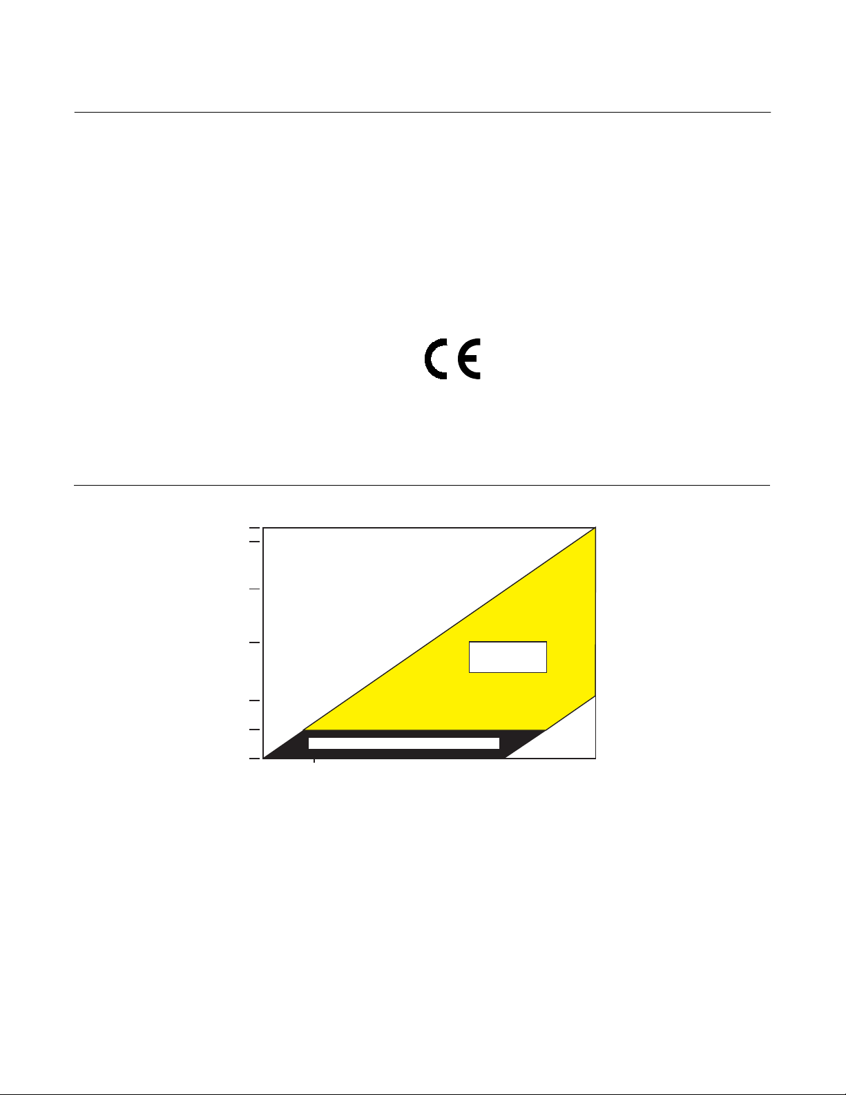
Power Supply and Load Requirements ......................... See Figure 1-4
Inputs (from O
Probe)................................................... Two wires - O2 signal
2
Two wires - type B thermocouple
Output ............................................................................ One 4-20 mA signal with superimposed digital HART
signal
Hazardous Area Certification......................................... Cenelec EEx ia IIC T4 or T5(2)
NEC Class I Div. I Group B,C,D
Fisher-Rosemount has satisfied all obligations coming from the European legislation
to harmonize the product requirements in
Europe.
Power Transient Protection ........................................... IEC 801-4
Shipping Weight............................................................. 10 lbs (4.5 kg)
INFRARED REMOTE CONTROL
Power Requirements .....................................................Three AAA batteries
Hazardous Area Certification......................................... Cenelec EEx ia IIC Class I, Div. I, Group A, B, C, D
(2)
Dependent on ambient temperature limits.
Model 3081FG
1848
1800
1500
1000
LOAD (OHMS)
500
250
0
12.0 VDC 18 VDC 40 VDC @ ZERO LOAD 42.4 VDC
LIFT OFF
WITHOUT HART COMMUNICATOR
POWER SUPPLY VOLTAGE
OPERATING
REGION
MAXIMUM
Figure 1-4. Power Supply and Load Requirements
1848
OHMS
@ 42.4
VDC
600
OHMS
@ 42.4
VDC
29750007
1-8 Description and Specifications Rosemount Analytical Inc. A Division of Emerson Process Management
Page 19
Model 3081FG
2
Instruction Manual
IB-106-3081 Rev. 1.5
September 2002
SECTION 2
INSTALLATION
2-1 PRE-INSTALLATION
a. Inspect
Carefully inspect the shipping container for
any evidence of damage. If the container is
damaged, notify the carrier immediately.
b. Packing List
Confirm that all items shown on the packing
list are present. Notify Rosemount Analytical
immediately if items are missing.
Before installing this equipment, read
the “Safety instructions for the wiring
and installation of this apparatus” at
the front of this Instruction Bulletin.
Failure to follow the safety instructions could result in serious injury or
death.
2-2 MECHANICAL INSTALLATION
Avoid installation locations near
steam soot blowers.
sensing point should be selected so
the process gas temperature falls
within a range of 550° to 1600°C
(1022° to 2912°F). Figure 2-1 provides
mechanical installation references.
2. Check the flue or stack for holes and
air leakage. The presence of this condition will substantially affect the accuracy of the oxygen reading. Therefore,
either make the necessary repairs or
install the probe upstream of any
leakage.
3. Ensure the area is clear of internal and
external obstructions that will interfere
with installation and maintenance access to the probe. Allow adequate
clearance for probe removal (Figure
2-1).
b. Installing Oxygen Probe
The probe was specially packaged to
prevent breakage due to handling. Do
not remove the padding material from
the probe until immediately before
installation.
a. Locating Oxygen Probe
1. The location of the oxygen probe in
the stack or flue is important for maximum accuracy in the oxygen analyzing
process. The probe must be positioned
so the gas it measures is representative of the process. Best results are
normally obtained if the probe is positioned near the center of the duct (4060% insertion). Longer ducts may require several analyzers since the O
can vary due to stratification. A point
too near the wall of the duct, or the inside radius of a bend, may not provide
a representative sample because of
the very low flow conditions. The
Rosemount Analytical Inc. A Division of Emerson Process Management Installation 2-1
2
Leave the probe inner protective cover
in place until installation. This is required to protect the ceramic cell during movement.
1. Ensure all components are available to
install the probe.
NOTE
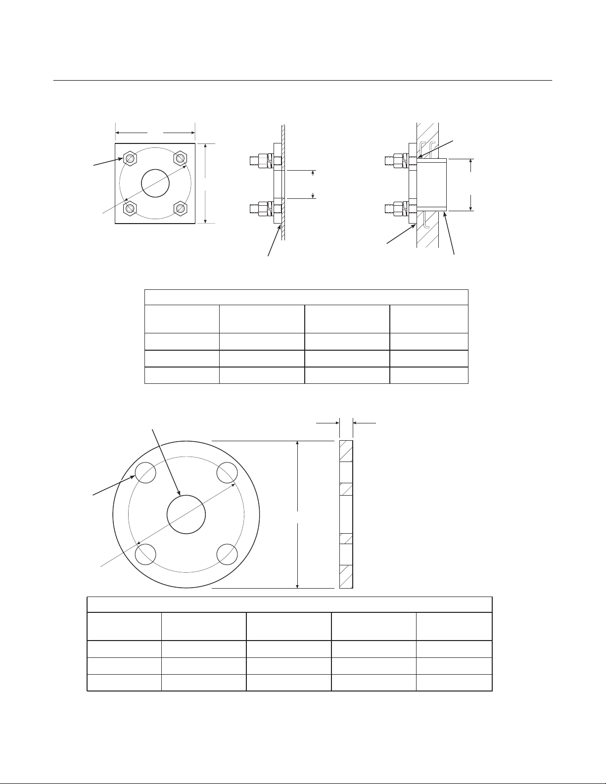
2. If using an optional adapter plate
(Figure 2-2) or an optional mounting
flange (Figure 2-3), weld or bolt the
component onto the duct. The through
hole in the stack or duct wall and refractory material must be 2 in. (50.8
mm) diameter, minimum.
Page 20
Instruction Manual
IB-106-3081 Rev. 1.5
September 2002
Model 3081FG
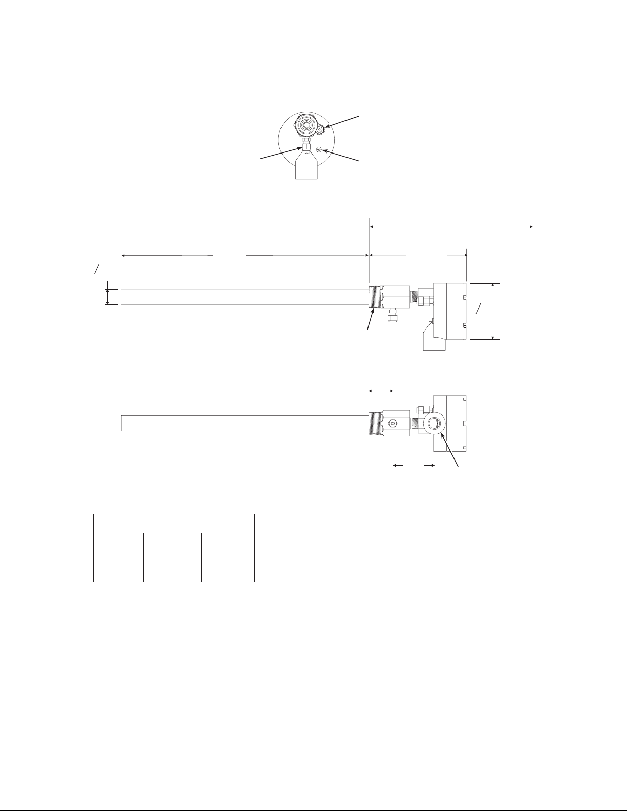
1/4 TUBE FITTING
(REFERENCE
AIR PORT)
1/4 TUBE FITTING
(CALIBRATION
CHECK GAS PORT)
REFERENCE
AIR VENT
FRONT VIEW
(REMOVAL ENVELOPE)
1.1
O
(29)
DIM “A”
1.25 NPT PROCESS
CONNECTION
7.1 (180)
DIM “B”
O
4.1
(109)
SIDE VIEW
1.8
(49)
TABLE 1. INSTALLATION (REMOVAL)
PROBE
20 IN.
26 IN.
34.625 IN.
DIM “A”
20 (508)
26 (660)
34.625 (880)
DIM “B”
31 (787)
37 (940)
46 (1170)
Figure 2-1. Probe Installation Details
BOTTOM VIEW
INSTALL WITH PORT AT
THE BOTTOM
3.0
(77)
NOTE: DIMENSIONS ARE IN INCHES WITH
MILLIMETERS IN PARENTHESES.
3/4 NPT
CONDUIT
PORT
29750001
2-2 Installation Rosemount Analytical Inc. A Division of Emerson Process Management
Page 21
Model 3081FG
2
Instruction Manual
IB-106-3081 Rev. 1.5
September 2002
A
B
C
NOTE: DIMENSIONS ARE
IN INCHES WITH
MILLIMETERS IN
PARENTHESES.
DIMENSION
“B” THREAD 0.625-11 M-16x2 M-12x1.75
“C” DIA. 4.75 (121) 5.71 (145) 5.12 (130)
METAL WALL
STACK OR DUCT
A
WELD OR BOLT ADAPTER
PLATE TO STACK OR DUCT.
JOINT MUST BE AIR TIGHT.
ANSI
4512C34G01
“A” 6.00 (153) 7.5 (191) 6.50 (165)
2.50 (63.5)
MIN. DIA.
JOINT MUST
BE AIR TIGHT
PLATE DIMENSIONS
DIN
4512C36G01
MASONRY WALL
STACK
3.00 SCHEDULE 40
PIPE SLEEVE
SUPPLIED BY CUSTOMER
JIS
4512C35G01
WELD PIPE TO
ADAPTER PLATE
3.50 (89)
O.D. REF
29750002
Figure 2-2. Optional Adapter Plate
TAP 1.25 NPT
B
A
C
FLANGE DIMENSIONS
ANSI
DIMENSION
“A” DIA. 6.00 (153) 7.28 (185) 6.10 (155) 9.00 (229)
“B” DIA. 0.75 (20) 0.71 (18) 0.59 (15) 0.50 (13)
“C” DIA. 4.75 (121) 5.71 (145) 5.12 (130) 7.68 (195)
5R10158H01
DIN
5R10158H02
0.50 (12.7)
NOTE: DIMENSIONS ARE IN
INCHES WITH MILLIMETERS
IN PARENTHESES.
JIS
5R10158H03
MODEL 450
5R10158H04
29750003
Figure 2-3. Optional Probe Mounting Flange
Rosemount Analytical Inc. A Division of Emerson Process Management Installation 2-3
Page 22
Instruction Manual
IB-106-3081 Rev. 1.5
September 2002
Model 3081FG
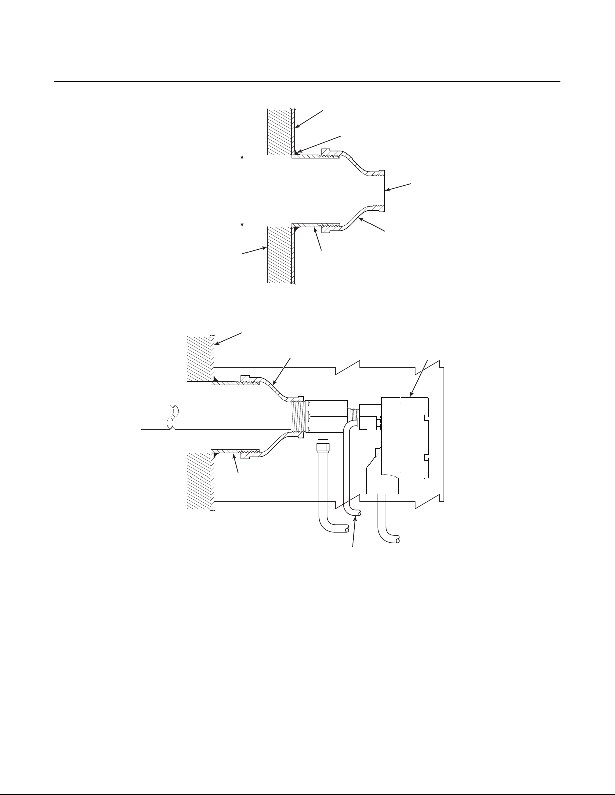
STACK OR DUCT
METAL WALL
WELD PIPE TO
METAL WALL
2.0 IN. (51 mm)
MIN. DIA.
REFRACTORY
SCHEDULE 40
STACK OR DUCT
METAL WALL
ADAPTER
2 IN. NPT
PIPE
1.25 NPT
CUSTOMER
SUPPLIED
ADAPTER
INSULATE IF EXPOSED
TO AMBIENT WEATHER
CONDITIONS
2 IN. NPT
SCHEDULE 40
PIPE
CALIBRATION
CHECK
GAS LINE
REFERENCE
AIR LINE
SYSTEM
CABLE
29750004
Figure 2-4. Horizontal Probe Installation
3. If the optional adapter plates are not
used, a 2 in. NPT, schedule 40, pipe
nipple (Figure 2-4) should be welded to
the stack or duct wall.
the adapter provides the pipe threads
needed for the probe’s process fitting.
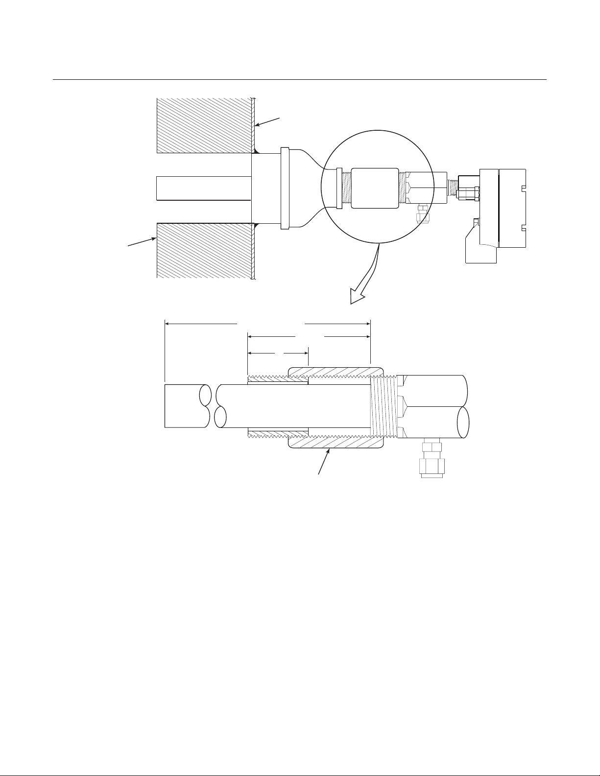
4. Where high particulate or slag is in the
flue gas stream, it may be desirable to
inset the probe in the refractory as
When a 2 in. NPT to 1.25 NPT adapter
is threaded to the welded pipe nipple,
shown in Figure 2-5. Use pipe couplings and nipples to adjust the probe
insertion depth.
2-4 Installation Rosemount Analytical Inc. A Division of Emerson Process Management
Page 23
Model 3081FG
2
REFRACTORY
STACK OR
DUCT METAL
PROBE LENGTH
A
WAL L
1.5 + A
Instruction Manual
IB-106-3081 Rev. 1.5
September 2002
DIMENSION A -- 1-5/8, 2-1/2, 3, OR
4 IN. 1.25 NPT SCHEDULE 40
PIPE NIPPLE
2 IN., 1.25 NPT
PIPE COUPLING
29750005
Figure 2-5. Adjusting Probe Insertion Depth
Rosemount Analytical Inc. A Division of Emerson Process Management Installation 2-5
Page 24
Instruction Manual
IB-106-3081 Rev. 1.5
September 2002
Model 3081FG
5. Use high temperature material (alumina wool) to seal around the probe
during insertion. This prevents hot
gases from escaping or cold air from
entering the stack or duct.
6. Initially insert the probe to a depth of 3
in. (76.2 mm) or 1/2 the depth of the
stack or duct refractory, whichever is
greater.
After initial insertion, do not insert the
probe at a rate exceeding 1 in. per minute (25.4 mm per minute) or damage
to the probe may result due to thermal
shock.
7. After initial insertion, insert the probe at
a rate of 1 in. (25.4 mm) per minute
until the probe is fully inserted.
8. Install anti-seize compound on the pipe
threads and screw the probe into the
process flange or adapter.
9. If insulation was removed to access the
duct work for probe mounting, make
sure the insulation is replaced afterward. See Figure 2-4.
If the ducts will be washed down during outage, MAKE SURE to power
down the probes and remove them
from the wash area.
c. Locating Model 3081 Transmitter
1. Ensure the Model 3081 Transmitter is
easily accessible for maintenance and
service and for using the infrared remote control (if applicable).
Do not allow the temperature of the
Model 3081 Transmitter exceed 65°C
(149°F) or damage to the unit may
result.
NOTE
Use anti-seize compound on threads
to ease future removal of probe.
The electrical conduit port should be
facing down for a horizontal probe installation. See Figure 2-4. In vertical
probe installations, orient the probe so
the system cable drops vertically from
the probe. Ensure the electrical conduit
is routed below the level of the terminal
block housing. This drip loop minimizes
the possibility that moisture will accumulate in the housing.
2. The ambient temperature of the transmitter housing must not exceed 65°C
(149°F). Locate the electronics in an
area where temperature extremes, vibration, and electromagnetic and radio
frequency interference are minimal.
3. Locate the Model 3081 Transmitter
within 150 ft (45.7 m) of the oxygen
probe due to wiring and signal
considerations.
2-6 Installation Rosemount Analytical Inc. A Division of Emerson Process Management
Page 25

Model 3081FG
2
Instruction Manual
IB-106-3081 Rev. 1.5
September 2002
d. Installing Model 3081 Transmitter
1. Ensure all components are available to
install the Model 3081 Transmitter.
2. Choose a method or location to mount
the transmitter.
(a) Flat Surface Mounting. The trans-
mitter may be mounted on a flat
COVER
LOCK
CIRCUIT
END
6.32
(160.5)
6.35
(161.3)
TERMINAL
END
THREADED CAP
(2 PLACES)
surface using the threaded mounting holes located on the bottom of
the transmitter housing. Refer to
Figure 2-6 for installation
references.
(b) Pipe Mounting. An optional pipe
mounting bracket is available for
this type of installation. Refer to
Figure 2-7 for installation
references.
TERMINAL BLOCK (TB)
TERMINAL END
CAP OMITTED
FOR CLARITY
(THIS VIEW)
1.32
(33.5)
O-RING
(2 PLACES)
NOTE: DIMENSIONS ARE IN INCHES
WITH MILLIMETERS IN
PARENTHESES.
3.68
(93.5)
Figure 2-6. Flat Surface Mounting Dimensional Information
3/4-14 NPT
(2 PLACES)
SURFACE
BY OTHERS
0.839
(21.31)
FLAT SURFACE MOUNTING
PAD HOLE PATTERN
1/4-20 THREADS
(4 PLACES)
0.839
(21.31)
26020003
Rosemount Analytical Inc. A Division of Emerson Process Management Installation 2-7
Page 26

Instruction Manual
IB-106-3081 Rev. 1.5
September 2002
6.35
(161.3)
COVER LOCK
6.9
(175.3)
Model 3081FG
TERMINAL
BLOCK (TB)
CIRCUIT
6.32
(160.5)
9.63
(244.6)
1.00
(25.4)
0.375 (9.525) DIA.
(4 MOUNTING
HOLES)
1.405
(35.687)
2.81
(71.374)
END
1.32
(33.5)
C
L
3.87
(98.3)
3.25
(82.55)
7.5
(190.5)
6.5
(165.1)
C
L
TERMINAL
END
3/4 -14 NPT
2 PLACES
3/4-14 FNPT
(2 PLACES)
5/16-18 NUT
4.00
(101.6)
TERMINAL END CAP
OMITTED FOR CLARITY
IN THIS VIEW.
2 IN. PIPE/WALL
MOUNTING BRACKET
(OPTION)
U-BOLT
(2 PLACES)
%
mAmA
1/4-20 THREADS
BRACKET HOLE PATTERN
FOR WALL MOUNTING
NOTE:
DIMENSIONS ARE IN INCHES WITH
MILLIMETERS IN PARENTHESES.
*SCREWS FURNISHED WITH
Figure 2-7. Pipe Mounting Dimensional Information
5/16 WASHER
U-BOLT
MOUNTING KIT ONLY. NOT
FURNISHED WITH
ANALYZER/TRANSMITTER.
BOTTOM VIEW
1/4-20 SCREW*
26020042
2-8 Installation Rosemount Analytical Inc. A Division of Emerson Process Management
Page 27

Model 3081FG
2
Instruction Manual
IB-106-3081 Rev. 1.5
September 2002
3. For correct viewing orientation, the display may be changed 90 degrees, using the following procedure:
(a) Refer to Figure 2-8. Loosen the
cover lock screw until the cover
lock is disengaged from the
knurled surface on the threaded
circuit end cap.
(b) Remove the circuit end cap.
(c) Remove the three screws retaining
the display board in place.
(d) Lift and rotate the display board 90
degrees either way.
(e) Reposition the display board on the
standoffs. Install and tighten all
three screws.
CIRCUIT END
CAP
(f) Install the circuit end cap and
tighten the cover lock screw to secure the cover lock in place.
2-3 ELECTRICAL INSTALLATION
All wiring must conform to local and national
codes.
For intrinsically safe applications, refer to drawing 1400184, page 10-2 of
this Instruction Bulletin.
Disconnect and lock out power before
connecting the unit to the power
supply.
Install all protective equipment covers
and safety ground leads after installation. Failure to install covers and
ground leads could result in serious
injury or death.
SCREW
DISPLAY
BOARD
90
O
90
O
HOUSING
Figure 2-8. Display Positioning Assembly
26020061
To meet the Safety Requirements of
IEC 1010 (EC requirement), and ensure
safe operation of this equipment, connection to the main electrical power
supply must be made through a circuit
breaker (min 10 A) which will disconnect all current-carrying conductors
during a fault situation. This circuit
breaker should also include a mechanically operated isolating switch. If
not, then another external means of
disconnecting the supply from the
equipment should be located close by.
Circuit breakers or switches must
comply with a recognized standard
such as IEC 947.
a. General
The power supply and signal wiring should
be shielded. Also, make sure the signal
wiring is grounded at the Model 3081
Transmitter end only. Do not ground the
signal loop at more than one point. Twisted
Rosemount Analytical Inc. A Division of Emerson Process Management Installation 2-9
Page 28

Instruction Manual
IB-106-3081 Rev. 1.5
September 2002
Model 3081FG
pairs are recommended. Ground the transmitter housing to an earth ground to prevent
unwanted electromagnetic interference
(EMI) or radio frequency interference (RFI).
NOTE
For optimum EMI/RFI immunity, shield
the 4-20 mA current loop cable and
enclose in an earth grounded metal
conduit.
NOTE
Never run signal or sensor wiring in
the same conduit, or open tray, with
power cables. Keep signal or sensor
wiring at least 12 in. (0.3 m) away from
other electrical equipment and 6.5 ft (2
m) from heavy electrical equipment.
It is necessary to prevent moisture from
entering the Model 3081 Transmitter housing. The use of weather-tight cable glands is
required. If conduit is used, plug and seal
connections on the transmitter housing to
prevent moisture accumulation in the terminal side of the housing.
signal is HART information that is accessible through a Model 275 Handheld Communicator or AMS software.
2. Two signals representing the O
and the cell temperature are supplied
to the Model 3081 Transmitter from the
oxygen probe.
3. Wiring connections for the Model 3081
Transmitter are shown in Figure 2-10.
NOTE
The ground arrangement shown in
Figure 2-10 limits the amount of noise
introduced into the electronics.
4. Connect wire shields to terminal 1.
Connect earth ground as shown.
value
2
Moisture accumulation in the transmitter housing can affect its performance
and may void its warranty.
b. Oxygen Probe Signal Connections
1. Two signals represent the O
value and
2
the cell temperature. The probe provides these values to the Model 3081
Transmitter for processing and signal
conditioning.
2. Wiring connections for the probe are
shown in Figure 2-9.
c. Model 3081 Transmitter 4-20 mA and
Signal Connections
1. A 4-20 mA signal represents the O
value. Superimposed on the 4-20 mA
TERMINAL
BLOCK
CONDUIT
THERMOCOUPLE + (GY)
2
Figure 2-9. Oxygen Probe Terminal Block
THERMOCOUPLE - (RD)
CELL - (WH)
CELL + (BK)
26020004
2-10 Installation Rosemount Analytical Inc. A Division of Emerson Process Management
Page 29

Model 3081FG
2
3
12
CELL + (BK)
6
5
4
FACTORY-INSTALLED
JUMPER
TERMINAL
BLOCK (TB1)
PROBE CABLE
SHIELD
GROUND
Instruction Manual
IB-106-3081 Rev. 1.5
September 2002
b. Reference Air Package
After the oxygen probe is installed, connect
the reference air set. Install the reference air
set according to Figure 2-12.
c. Instrument Air (Reference Air)
CELL - (WH)
THERMOCOUPLE - (RD)
THERMOCOUPLE + (GY)
8
9
7
10
11
12
13
14
15
16
EARTH
GROUND
TERMINALS
4-20 mA (-)
4-20 mA (+)
Instrument air is required for reference. Use
10 psig (68.95 kPa gage) minimum, 225
psig (1551.38 kPa gage) at 0.2 scfh (100
ml/min.); less than 40 parts-per-million total
hydrocarbons. Regulator outlet pressure
should be set at 5 psi (35 kPa).
d. Calibration Check Gas
CELL AND
THERMOCOUPLE
CONDUITS
NOTE:
RUN CELL AND THERMOCOUPLE SIGNALS IN
SEPARATE CONDUIT FROM 4-20 mA LINE.
Figure 2-10. Model 3081 Transmitter Terminal
Block
2-4 PNEUMATIC INSTALLATION
a. General
Reference air is required for O
calculation,
2
and calibration check gas is required during
a calibration check. Refer to Figure 2-11 for
the gas connections on the oxygen probe.
4-20 mA
26020005
Two calibration check gas concentrations
are used with the Two-Wire In Situ Oxygen
Analyzer: Low Gas - 0.4% O
- 8% O
, each with the balance in nitrogen.
2
and High Gas
2
Do not use 100% nitrogen. See Figure 2-11
for the probe connections. Set both calibration check gases at the same flow rate: 5
scfh (2.5 L/min).
1/4 TUBE FITTING
(REFERENCE AIR PORT)
1/4 TUBE FITTING
(CALIBRATION CHECK
GAS PORT)
REFERENCE
AIR VENT
26020006
Figure 2-11. Oxygen Probe Gas Connections
Rosemount Analytical Inc. A Division of Emerson Process Management Installation 2-11
Page 30

Instruction Manual
IB-106-3081 Rev. 1.5
September 2002
Model 3081FG
4.81 (122.17)
FLOW SET
POINT KNOB
0.125-27 NPT FEMALE
OUTLET CONNECTION
1
2
1.19
(30.22)
DRAIN VALVE
OUTLET
10.0
(254)
REF
3.12 (79.25) MAX
3
(SUPPLIED BY CUSTOMER)
1/4” TUBE
2.250 (57.15)
2.0
(50.80)
1.50
(38.10)
1 FLOWMETER 0.2-2.0 SCFH 771B635H08
2 2" PRESSURE GAGE 0-15 PSIG 275431-006
3 COMBINATION FILTER-REG. 0-30 PSIG 4505C21G01
TO PROBE
NOTE: DIMENSIONS ARE IN INCHES WITH
0.25-18 NPT FEMALE
INLET CONNECTION
2 MOUNTING HOLES
3.19 (81.03) LG
THROUGH BODY FOR
0.312 (7.92) DIA BOLTS
REF AIR SET
263C152G05
MILLIMETERS IN PARENTHESES.
8.50
(215.90)
MAX
INSTRUMENT
AIR SUPPLY
10-225 PSIG
MAX PRESSURE
SCHEMATIC HOOKUP FOR REFERENCE AIR SUPPLY ON OXYGEN PROBE.
26020034
Figure 2-12. Air Set, Plant Air Connection
2-12 Installation Rosemount Analytical Inc. A Division of Emerson Process Management
Page 31

Model 3081FG
3
Instruction Manual
IB-106-3081 Rev. 1.5
September 2002
SECTION 3
STARTUP AND OPERATION
c. Operating Display
Install all protective equipment covers
and safety ground leads before
equipment startup. Failure to install
covers and ground leads could result
in serious injury or death.
3-1 GENERAL
a. Verify Mechanical Installation
Ensure the Two-Wire In Situ Oxygen Analyzer is installed correctly. See paragraph
2-2 for mechanical installation information.
b. Verify Terminal Block Wiring
Ensure the wiring of both the oxygen probe
terminal block and Model 3081 Transmitter
terminal block is correct. Refer to paragraph
2-3 for electrical installation and wiring
information.
3-2 POWER UP
a. General
The Two-Wire In Situ Oxygen Analyzer displays the current oxygen reading on the
LCD face of the Model 3081 Transmitter.
The O
concentration, cell temperature, and
2
4-20 mA output current are displayed as
shown in Figure 3-1. This and other information may also be accessed using
HART/AMS.
After the probe has reached operating
temperatures, the Model 3081 Transmitter
display should look similar to Figure 3-1.
The display will now track the O
tion, cell temperature, and 4-20 mA output
current.
O CONCENTRATION
2
CELL
TEMPERATURE
Figure 3-1. Normal Operation Display
concentra-
2
%
mA
4-20 mA OUTPUT
26020007
%
b. Startup Display
When the probe is first inserted into the
stack, some time is required until minimum
operating temperatures [550°C (1022°F)]
mA
are reached. Some time is also required for
the electronics to reach an operating state.
Therefore, when the unit is first powered up,
a faulted operation display as shown in Figure 3-2 may be displayed by the transmitter
until the probe operating temperatures are
26020008
reached and the electronics are working
properly (approximately 5 minutes).
Rosemount Analytical Inc. A Division of Emerson Process Management Startup and Operation 3-1
Figure 3-2. Faulted Operation Display
Page 32

Instruction Manual
IB-106-3081 Rev. 1.5
September 2002
Model 3081FG
3-3 REESTABLISHING PROPER CALIBRATION
CHECK GAS FLOW RATE
The calibration check gas flow must be enough
to ensure no combustion flue gases mix with the
calibration check gases and only clean, good
calibration check gas surrounds the cell without
expending excess gas (Figure 3-3). Monitor the
O
concentration using an IRC or HART Com-
2
municator. Set the calibration check gas flow
rate as follows:
NOTE
Only set the calibration check gas flow
rate at startup. It is not necessary to
perform this procedure for each calibration check.
FLUE GAS
PROTECTIVE
TUBE
a. Adjust the calibration check gas flow to 5
scfh (2.5 L/min.) to ensure the cell is surrounded by calibration check gas. Due to
the cooling effect of the gas, the cell temperature will decrease slightly, causing the
O
concentration to drop. Once the elec-
2
tronics compensates for this effect, the O
concentration will stabilize.
b. Next, slowly reduce the calibration check
gas flow until the O
concentration changes,
2
which indicates that the calibration check
and flue gases are mixing. Increase the flow
rate until this effect is eliminated.
STACK OR DUCT
METAL WALL
2
CALIBRATION
GAS
CELL
REFRACTORY
CALIBRATION
CHECK GAS LINE
REFERENCE
AIR LINE
Figure 3-3. Proper Calibration Check Gas Flow Rate
26020062
3-2 Startup and Operation Rosemount Analytical Inc. A Division of Emerson Process Management
Page 33

Model 3081FG
3
Instruction Manual
IB-106-3081 Rev. 1.5
September 2002
3-4 OPERATION
a. Overview
This section explains the operator controls
and displays of the Two-Wire In Situ Oxygen Analyzer. The use of the Infrared Remote Control (IRC) and the Model 3081
Transmitter Liquid Crystal Display (LCD) are
described in detail. HART/AMS operation is
not covered here but is discussed in
Section 4, HART/AMS.
b. Display
The Model 3081 Transmitter LCD displays
the O
concentration, cell temperature, and
2
CIRCUIT
END
4-20 mA output current during normal operation (see Figure 3-4). The LCD will also
display fault conditions when they occur. To
interact with the transmitter, use the IRC
and navigate through a series of menus
displayed on the LCD.
c. Menu Tree
The screens that can be displayed are
shown in the menu tree of Figure 3-5.
These screens are displayed on the LCD
and are accessed using the IRC keypad.
TERMINAL
END
MODEL 3081 TRANSMITTER
ELECTRONICS HOUSING
%
mA
26020031
Figure 3-4. Normal Operation Display
Rosemount Analytical Inc. A Division of Emerson Process Management Startup and Operation 3-3
Page 34

Instruction Manual
IB-106-3081 Rev. 1.5
September 2002
Model 3081FG
ON STARTUP
RESET
OR ON
FROM ANY
SCREEN
NEXT
PROG
CODE
555 ENTER
DISPLAY
CODE
FAULT VAL
NEXT
UPPER RANGE
VAL
NEXT
CELL T HI
NEXT
RESET MAX
CELL T
NEXT
SET O2 FILTER
TIME
NEXT
TRIM 4 mA ?
NEXT
TRIM 20 mA ?
NEXT
SET HI BOTTLE
O2
NEXT
SET LO BOTTLE
O2
NEXT
SET O2
TRACKING
NEXT
PROCESS DISPLAY
OPERATION
PROCESS DISPLAY
OPERATION
2
NEXT
1
PROGRAM
ENTER
EXIT
ENTER
EXIT
NORMAL
FAULTED
MENU
TRIM 4 mA
TRIM 20 mA
EXIT
ON FROM
ANY SCREEN
EXIT
WITHOUT
EXPLICITY
STATED
DIAG
SHOW FAULT IN MANUAL?
T/C mV ACCEPT HIGH O2
O2 CELL mV ACCEPT LOW O2
CELL
IMPEDANCE
PREVIOUS
SLOPE
PREVIOUS
CONSTANT
MAX CELL T
SW VER
UNIT SER #
SW BUILD
NUMBER
NEXT
SW BUILD DATE
ENTER
NEXT NEXT ENTER
NEXT NEXT
NEXT NEXT
NEXT NEXT
NEXT
EXIT
EXIT
DIAGNOSTICS
NEXT
NEXT
NEXT
NEXT
NEXT
FAULT
(IF PRESENT)
FAULT
(IF PRESENT)
MENU
CAL
SLOPE
CONSTANT
RESET OR EXIT
1 - USER ENTERS DISPLAY
ANALYZER CODE
2 - USER ENTERS ANALYZER
ACCESS CODE OR ANALYZER
ACCESS CODE = SECURITY
DISABLE VALUE
CALCHECK
MENU
SET CODE
26020033
Figure 3-5. Model 3081 Transmitter Menu Tree
3-4 Startup and Operation Rosemount Analytical Inc. A Division of Emerson Process Management
Page 35

Model 3081FG
3
Instruction Manual
IB-106-3081 Rev. 1.5
September 2002
d. Navigation
The IRC in Figure 3-6 is used to interact
with the Model 3081 Transmitter and navigate through the screens on the LCD.
1. Hold the IRC within 6 ft (1.8 m) of the
Model 3081 Transmitter and within 15
degrees from the centerline of the
transmitter LCD. The amount of ambient light may also affect IRC
performance.
NOTE
The LCD may react slowly to IRC
commands. Allow sufficient time between key presses to avoid undesired
or repeated commands from accumulating in the command queue.
2. Use the keys on the IRC to navigate
through the menu screens. Refer to
Figure 3-6. General usage is as
follows:
(h) ENTER. Initiates the editing proc-
ess and causes the most significant digit of the edited item to start
flashing. Also processes the entry
so the previous value updates to
the new value entered using the arrow keys. Failure to press ENTER
before exiting a screen will cancel
the input value and revert to the
previous value.
(i) NEXT. Accesses the next user
screen as shown in the menu tree.
Any non-entered number in the exited state will be ignored, and the
previous data will be used.
(j) EXIT. Exits from sub-branches of
the menu tree where an exit option
is explicitly shown. Otherwise, returns to the PROCESS DISPLAY
screen at the top of the menu tree.
Any non-entered number in the exited state will be ignored, and the
previous data will be used.
(a) RESET. Returns to the PROCESS
DISPLAY screen at the top of the
menu tree. Any non-entered number in the exited state will be ignored, and the previous data will
be used.
(b) HOLD. Not used.
(c) Left/Right Arrow. Moves left and
right among editable digits on the
display.
(d) Up/Down Arrow. Increases or de-
creases the value of the currently
selected digit on the display.
(e) CAL. Accesses the CALCHECK
MENU branch of the menu tree.
Only works from the PROCESS
DISPLAY screen.
(f) PROG. Accesses the PROGRAM
MENU branch of the menu tree.
Only works from the PROCESS
DISPLAY screen.
(g) DIAG. Accesses the DIAGNOS-
TICS MENU branch of the menu
tree. Only works from the PROCESS DISPLAY screen.
RESET HOLD
ENTERCAL
PROG
DIAG EXIT
REMOTE CONTROL
ROSEMOUNT
NEXT
MODEL 3081
FISHER-ROSEMOUNT
26020032
Figure 3-6. Infrared Remote Control (IRC)
Rosemount Analytical Inc. A Division of Emerson Process Management Startup and Operation 3-5
Page 36

Instruction Manual
IB-106-3081 Rev. 1.5
September 2002
3-5 PROGRAM MENU
The PROGRAM MENU branch of the menu
tree allows you to program and edit some process parameters, faults, outputs, and security
codes. To access this branch of the menu tree,
press the PROG key on the IRC when in the
PROCESS DISPLAY screen (Normal or
Faulted). If security is enabled, you must enter
the analyzer code to gain further access to the
screens in this branch. Each screen in this
branch is accessed sequentially using the NEXT
key. Refer to Figure 3-5 during the following
menu and screen descriptions.
Model 3081FG
O CONCENTRATION
2
%
NOTE
To edit a screen value, press ENTER to
access the data field. Use the left and
right arrow keys to move among the
digits in the data field. Note that the
editable position will be flashing. To
change the value of a digit, use the up
and down arrow keys to increase or
decrease the value. When finished editing, press ENTER to accept the value.
To go to the next screen in the menu,
press NEXT.
a. CODE
Refer to Figure 3-7. After pressing the
PROG key, this screen will display if security is enabled (see paragraph 3-5m). Use
this screen to identify a specific analyzer in
a process to prevent accessing an adjacent
analyzer when using the IRC.
Press ENTER to begin editing. At this point,
you can either specify the analyzer by its
access code or view its code if it is unknown.
1. To gain further access to the screens
in the PROGRAM MENU branch, enter the correct three-digit analyzer access code using the arrow keys and
press ENTER. If security is disabled,
this screen does not appear and the
system displays the FAULT VAL
screen.
2. If the analyzer access code is unknown, enter 555 and press ENTER to
access the DISPLAY CODE screen. In
that screen, you will be able to view the
analyzer access code.
ANALYZER
ACCESS CODE
OR SECURITY
ACCESS CODE
Figure 3-7. CODE
b. DISPLAY CODE
Refer to Figure 3-8. This screen is accessible from the CODE screen by entering 555
and pressing ENTER. The DISPLAY CODE
screen identifies the analyzer access code
so you can return to the CODE screen and
enter the code as described in paragraph
3-5a. To return to the CODE screen, press
NEXT.
O CONCENTRATION
2
%
ANALYZER
ACCESS CODE
Figure 3-8. DISPLAY CODE
26020009
26020047
3-6 Startup and Operation Rosemount Analytical Inc. A Division of Emerson Process Management
Page 37

Model 3081FG
3
O CONCENTRATION
2
%
mA
INDICATOR
FAULT VALUE
26020010
Instruction Manual
IB-106-3081 Rev. 1.5
September 2002
lowed cell temperature before a fault condition is indicated. Press ENTER to begin
editing. Use the arrow keys to select and
change the value. The value must be between 550° and 1600°C. Press ENTER to
accept the value. Pressing NEXT displays
the RESET MAX CELL T screen.
O CONCENTRATION
2
%
Figure 3-9. FAULT VAL
c. FAULT VAL
Refer to Figure 3-9. Use this screen to set
the value that the 4-20 mA output will drive
to and display during a fault condition. Press
ENTER to begin editing. Use the arrow keys
to enter a fault value. The fault value can be
between 3.8 and 24 mA. Then, press ENTER to accept the value. Pressing NEXT
displays the UPPER RANGE VAL screen.
Refer to Section 6, TROUBLESHOOTING,
for the actual fault conditions.
d. UPPER RANGE VAL
Refer to Figure 3-10. Use this screen to set
the value of the upper range limit. This
value is the maximum limit of the O
centration measurement and is used to
scale the 4-20 mA output. Press ENTER to
begin editing. Use the arrow keys to select
and change the value. The upper range
value can be between 0 and 25%. Then,
press ENTER to accept the value. Pressing
NEXT displays the CELL T HI screen.
e. CELL T HI
Refer to Figure 3-11. Use this screen to set
the value of the upper cell temperature fault
condition. This value is the maximum al-
con-
2
%
RANGE LIMIT
Figure 3-10. UPPER RANGE VAL
O CONCENTRATION
2
%
UPPER CELL
TEMPERATURE
FAULT VALUE
Figure 3-11. CELL T HI
UPPER
26020011
26020012
Rosemount Analytical Inc. A Division of Emerson Process Management Startup and Operation 3-7
Page 38

Instruction Manual
IB-106-3081 Rev. 1.5
September 2002
Model 3081FG
f. RESET MAX CELL T
Refer to Figure 3-12. The transmitter tracks
the maximum cell temperature obtained.
Use this screen to reset the maximum cell
temperature attained value to the current
cell temperature. Press ENTER to begin
editing. Use the arrow keys to select and
change the value (Y/N). Then, press ENTER to accept the value. Pressing NEXT
displays the SET O
FILTER TIME screen.
2
O CONCENTRATION
2
%
g. SET O
FILTER TIME
2
Refer to Figure 3-13. In some applications,
it is beneficial to dampen the raw O
coming from the cell. Use this screen to
enter the amount of time it will take the O
reach 90% of the new reading. Press ENTER to begin editing. Use the arrow keys to
select and change the screen value to the
O
filter value (in seconds). Enter a value
2
between 0 and 300 seconds and press ENTER to accept the value. Press NEXT to
access the TRIM 4 mA? screen.
h. TRIM 4 mA?
Refer to Figure 3-14. Use this screen to trim
the 4 mA value of the 4-20 mA output.
NOTE
Before trimming the 4 mA value, you
must break the loop to add the ammeter. Power down the unit, connect the
ammeter in series with Model 3081
Transmitter terminals 15(-) and 16(+),
power up the unit, and return to the
TRIM 4 mA? screen.
signal
2
2
to
Y/N (TO RESET
MAXIMUM CELL
TEMPERATURE)
Figure 3-12. RESET MAX CELL T
O CONCENTRATION
2
%
ANALYZER
ACCESS CODE
Figure 3-13. SET O2 FILTER TIME
26020013
26020047
Press ENTER to begin editing. Use the arrow keys to select and change the screen
value to the value displayed on the installed
ammeter. Press ENTER to accept the
value. After the value is entered, the unit
calibrates itself to ensure it outputs 4 mA.
Both the display and the ammeter will display 4 mA. Pressing EXIT returns to the initial TRIM 4 mA? screen, and pressing
NEXT displays the TRIM 20 mA? screen.
O CONCENTRATION
2
%
26020014
Figure 3-14. TRIM 4 mA?
3-8 Startup and Operation Rosemount Analytical Inc. A Division of Emerson Process Management
Page 39

Model 3081FG
3
Instruction Manual
IB-106-3081 Rev. 1.5
September 2002
O CONCENTRATION
2
%
26020015
Figure 3-15. TRIM 20 mA?
i. TRIM 20 mA?
Refer to Figure 3-15. Use this screen to trim
the 20 mA value of the 4-20 mA output.
NOTE
Before trimming the 20 mA value, you
must break the loop to add the ammeter. Power down the unit, connect the
ammeter in series with Model 3081
Transmitter terminals 15(-) and 16(+),
power up the unit, and return to the
TRIM 4 mA? screen.
Press ENTER to begin editing. Use the arrow keys to select and change the screen
value to the value displayed on the installed
ammeter. Press ENTER to accept the
value. After the value is entered, the unit
calibrates itself to ensure it outputs 20 mA.
Both the display and the ammeter will update to 20 mA. Pressing EXIT returns to the
initial TRIM 20 mA? screen, and pressing
NEXT displays the SET HI BOTTLE O
screen.
O CONCENTRATION
2
%
HIGH CALIBRATION
CHECK GAS O
PERCENTAGE
Figure 3-16. SET HI BOTTLE O
2
2
26020049
the value. Press NEXT to display the SET
LO BOTTLE O
k. SET LO BOTTLE O
screen.
2
2
Refer to Figure 3-17. Use this screen to
identify, within the electronics, the percentage of O
used as the low calibration check
2
gas. Press ENTER to begin editing. Use the
arrow keys to select and change the screen
value to the O
percentage of the low cali-
2
bration check gas. Press ENTER to accept
the value. Press NEXT to display the SET
O
TRACKING screen.
2
O CONCENTRATION
2
%
2
j. SET HI BOTTLE O
2
Refer to Figure 3-16. Use this screen to
identify, within the electronics, the percentage of O
gas. Press ENTER to begin editing. Use the
arrow keys to select and change the screen
value to the O
bration check gas. Press EN TER to accept
Rosemount Analytical Inc. A Division of Emerson Process Management Startup and Operation 3-9
used as the high calibration check
2
percentage of the high cali-
2
LOW CALIBRATION
CHECK GAS O
PERCENTAGE
Figure 3-17. SET LO BOTTLE O
2
26020050
2
Page 40

Instruction Manual
IB-106-3081 Rev. 1.5
September 2002
Model 3081FG
O CONCENTRATION
2
%
TRACK O
DURING CALCHECK
Figure 3-18. SET O2 TRACKING
l. SET O
TRACKING
2
Refer to Figure 3-18. Use this screen to
permit the 4-20 mA line to track the O
during a calibration check. Press ENTER to
begin editing. Use the arrow keys to select
Y or N. Entering Y (yes) will allow the 4-20
mA line to track the O
value during the
2
calibration check. Entering N (no) will hold
the O
value steady during the calibration
2
check. Press ENTER to accept the value.
Press NEXT to display the SET CODE
screen.
m. SET CODE
2
26020051
value
2
O CONCENTRATION
2
%
26020016
Figure 3-19. SET CODE
returns to the FAULT VAL screen at the beginning of the PROGRAM MENU.
n. Model 3081 Transmitter Parameters
Table 3-1 lists the range and default value
of operator-adjustable variables used by the
Model 3081 Transmitter. These variables
may all be changed from the PROGRAM
MENU screens.
Table 3-1. Model 3081 Transmitter Parameters
Parameter Range Default
Refer to Figure 3-19. Use this screen to set
the security code for the Model 3081
Transmitter. Press ENTER to begin editing.
Use the arrow keys to select and change
the value. Select any value between 000
and 999, excluding 000 and 555. Code 000
Indicator Fault
Value
high value (24 mA)
low value (3.8 mA)
low value
(3.8 mA)
Upper Range Limit 2.0-25.0% 10.0%
Upper Cell Temp.
650-1600°C 1600°C
Fault Value
indicates that no code is set. Code 555 accesses the DISPLAY CODE screen. Press
ENTER to accept the value. Pressing NEXT
3-10 Startup and Operation Rosemount Analytical Inc. A Division of Emerson Process Management
Analyzer Access
Code
000-999 (excluding
000 and 555)
000 (no
code)
Page 41

Model 3081FG
3
Instruction Manual
IB-106-3081 Rev. 1.5
September 2002
Figure 3-20. SHOW FAULT
3-6 DIAGNOSTICS MENU
The DIAGNOSTICS MENU branch of the menu
tree allows you to examine outputs, current
faults, and unit information. None of the items in
the DIAGNOSTICS MENU are editable. This
branch of the menu tree may be accessed by
pressing DIAG on the IRC when in the PROCESS DISPLAY screen (Normal or Faulted).
Each screen in this branch is accessed sequentially by pressing NEXT. Refer to Figure 3-5
during the following menu and screen
descriptions.
%
26020017
%
THERMOCOUPLE mV
26020018
Figure 3-21. T/C mV
CELL mV
c. O
2
Refer to Figure 3-22. Use this screen to examine the O
cell mV output. Pressing
2
NEXT accesses the CELL IMPEDANCE
screen.
a. SHOW FAULT
Refer to Figure 3-20. After pressing DIAG,
this screen displays. Pressing ENTER ac-
%
cesses a screen displaying the current fault
(if any). If more than one fault exists, and
you are in the FAULT screen, press NEXT
to go to the next fault. Information on the
fault screens can be found in Section 6,
TROUBLESHOOTING. Press EXIT to return from this fault sub-menu and press
NEXT to access the T/C mV screen.
b. T/C mV
Refer to Figure 3-21. Use this screen to examine the cell thermocouple mV output.
Three decimal places are displayed. Pressing NEXT accesses the O
screen.
Rosemount Analytical Inc. A Division of Emerson Process Management Startup and Operation 3-11
CELL mV
2
Figure 3-22. O2 CELL mV
O CELL mV
2
26020019
Page 42

Instruction Manual
IB-106-3081 Rev. 1.5
September 2002
Model 3081FG
O CONCENTRATION
2
%
O CELL
IMPEDANCE STATUS
2
26020020
Figure 3-23. CELL IMPEDANCE
d. CELL IMPEDANCE
Refer to Figure 3-23. Use this screen to examine the O
cell impedance status. GOOD
2
indicates the cell is operating normally.
WARN indicates the cell has degraded but
is still operational. HI indicates that the cell
has degraded but is still operational; however, failure will occur soon. Pressing NEXT
accesses the PREVIOUS SLOPE screen.
O CONCENTRATION
2
%
CALCHECK CELL
SLOPE VALUE
Figure 3-24. PREVIOUS SLOPE
f. PREVIOUS CONSTANT
Refer to Figure 3-25. Use this screen to examine the cell zero constant calculated from
the most recent calibration check. The constant represents the voltage generated by
the cell when no difference exists between
the amount of O
on the reference and pro-
2
cess sides of the cell. Press NEXT to access the MAX CELL T screen.
26020052
O CONCENTRATION
NOTE
2
Temperature influences cell impedance. Wait until the cell is at operating
temperature before checking cell impedance. If checked before the cell
%
reaches operating temperature [550°C
(1022°F)], this screen displays a fail
indication.
e. PREVIOUS SLOPE
Refer to Figure 3-24. Use this screen to examine the slope calculated from the most
recent calibration check. The slope is the
amount of cell voltage generated for a given
O
value. For each calibration check, record
2
the slope over the life of the probe. Tracking
CALCHECK CELL
CONSTANT VALUE
26020053
the slope will indicate if the probe is degrading. Press NEXT to access the PREVI-
Figure 3-25. PREVIOUS CONSTANT
OUS CONSTANT screen.
3-12 Startup and Operation Rosemount Analytical Inc. A Division of Emerson Process Management
Page 43

Model 3081FG
3
Instruction Manual
IB-106-3081 Rev. 1.5
September 2002
j. SW BUILD NUMBER
Use this screen to see the software build
number for the Model 3081 Transmitter.
%
Pressing NEXT accesses the SW BUILD
DATE screen.
k. SW BUILD DATE
Use this screen to see the software build
date for the Model 3081 Transmitter.
Pressing NEXT returns to the beginning of
the DIAGNOSTICS MENU branch (the
SHOW FAULT screen).
TEMPERATURE
MAXIMUM
Figure 3-26. MAX CELL T
g. MAX CELL T
Refer to Figure 3-26. Use this screen to examine the maximum temperature attained
by the O
cell. This value can be reset under
2
the PROGRAM MENU. Pressing NEXT
accesses the SW VER screen.
h. SW VER
Use this screen to see the software version
number for the Model 3081 Transmitter.
Pressing NEXT accesses the UNIT SER #
screen.
i. UNIT SER #
Use this screen to see the unit serial number for the Model 3081 Transmitter. Pressing NEXT accesses the SW BUILD
NUMBER screen.
CELL
26020021
3-7 CALCHECK MENU
The CALCHECK MENU branch of the menu
tree (Figure 3-5) allows you to perform a calibration check of the analyzer. Before performing
a calibration check, ensure the high calibration
check gas and low calibration check gas O
percentages are entered into the electronics via
the PROGRAM MENU. To set these values,
refer to paragraphs 3-5j and 3-5k.
Once these values are set, access the CALCHECK MENU branch by pressing CAL on the
IRC when in the PROCESS DISPLAY screen
(Normal or Faulted). Each screen in this branch
identifies a process step in the calibration check
procedure. The first screen in the sequence is
the IN MANUAL? screen.
2
Rosemount Analytical Inc. A Division of Emerson Process Management Startup and Operation 3-13
Page 44

Instruction Manual
IB-106-3081 Rev. 1.5
September 2002
a. IN MANUAL?
Refer to Figure 3-27.
Failure to remove the analyzer from
automatic control loops prior to performing this procedure may result in a
dangerous operating condition.
Model 3081FG
O CONCENTRATION
2
%
If the O2 output value is used in any automatic process control loops, the loop must
be placed in manual before beginning a
calibration check.
Once the analyzer is removed from any
automatic control loops, press ENTER to
edit the screen. Use the arrow keys to select Y (yes) and press ENTER to process
the selection and to display the ACCEPT
HIGH O
screen.
2
O CONCENTRATION
2
%
%
HIGH CALIBRATION
CHECK GAS O VALUE
Figure 3-28. ACCEPT HIGH O
b. ACCEPT HIGH O
2
2
Refer to Figure 3-28. After pressing ENTER
to begin the calibration check, the high calibration check gas starts to flow. After waiting approximately three minutes for the
displayed O
value to settle, press NEXT to
2
accept the high calibration check gas reading and apply the low calibration check gas.
The next screen to display is the ACCEPT
LOW O
c. ACCEPT LOW O
screen.
2
2
2
26020055
Refer to Figure 3-29. Once the low calibration check gas is applied, wait approxi-
Y/N (FOR USER
RESPONSE)
26020054
mately three minutes for the displayed O
value to settle. Once the value settles, press
NEXT to accept the reading and to display
the SLOPE screen.
2
Figure 3-27. IN MANUAL?
3-14 Startup and Operation Rosemount Analytical Inc. A Division of Emerson Process Management
Page 45

Model 3081FG
3
O CONCENTRATION
2
%
%
LOW CALIBRATION
CHECK GAS O VALUE
2
26020056
Instruction Manual
IB-106-3081 Rev. 1.5
September 2002
e. CONSTANT
Refer to Figure 3-31. Use this screen to examine the cell zero constant calculated from
the current calibration check. The constant
represents the voltage generated by the cell
when no difference exists between the
amount of O
sides of the cell. Note this value for comparison against future calibration checks.
Press RESET or EXIT to return to the
PROCESS DISPLAY screen.
on the reference and process
2
O CONCENTRATION
2
Figure 3-29. ACCEPT LOW O
2
d. SLOPE
Refer to Figure 3-30. Use this screen to examine the slope calculated from current
calibration check. The slope is the amount
of cell voltage generated for a given O
value. After each calibration check, record
the slope over the life of the probe. Tracking
the slope will indicate if the probe is degrading. Press NEXT to access the CONSTANT screen.
O CONCENTRATION
2
%
%
2
CALCHECK CELL
CONSTANT VALUE
26020058
Figure 3-31. CONSTANT
CALCHECK CELL
SLOPE VALUE
26020057
Figure 3-30. SLOPE
Rosemount Analytical Inc. A Division of Emerson Process Management Startup and Operation 3-15
Page 46

Instruction Manual
IB-106-3081 Rev. 1.5
September 2002
Model 3081FG
3-16 Startup and Operation Rosemount Analytical Inc. A Division of Emerson Process Management
Page 47

Model 3081FG
4
Instruction Manual
IB-106-3081 Rev. 1.5
September 2002
SECTION 4
HART/AMS
4-1 OVERVIEW
The HART Communicator is a handheld communications interface device. It provides a
common communications link to all microprocessor-based instruments that are HART compatible. The handheld communicator contains
an 8 x 21 character liquid crystal display (LCD)
and 25 keys. A pocket-sized manual, included
with the HART Communicator, details the specific functions of all the keys.
To interface with the Two-Wire In Situ Oxygen
Analyzer, the HART Communicator requires a
termination point along the 4-20 mA current loop
and a minimum load resistance of 250 ohms
between the communicator and the power supply. The HART Communicator accomplishes its
task using a frequency shift keying (FSK) technique. With the use of FSK, high-frequency
digital communication signals are superimposed
on the 4-20 mA transmitter current loop. The
communicator does not disturb the 4-20 mA
signal since no net energy is added to the loop.
The HART Communicator may be interfaced
with a personal computer (PC) providing special
software has been installed. To connect the
HART Communicator to a PC, an interface
adapter is required. Refer to the proper HART
Communicator documentation regarding the PC
interface option.
4-2 HART COMMUNICATOR SIGNAL LINE
CONNECTIONS
The HART Communicator can connect to the
Two-Wire In Situ Oxygen Analyzer analog output signal line at any wiring termination in the 420 mA current loop. There are two methods of
connecting the HART Communicator to the signal line. For applications in which the signal line
has a load resistance of 250 ohms or more, refer to method 1 and Figure 4-1. For applications
in which the signal line load resistance is less
than 250 ohms, refer to method 2 and Figure
4-2.
Rosemount Analytical Inc. A Division of Emerson Process Management HART/AMS 4-1
Page 48

Instruction Manual
IB-106-3081 Rev. 1.5
September 2002
7
6
5
4
3
12
8
9
4-20 mA
Model 3081FG
10
11
12
13
14
15
16
+
4-20 mA SIGNAL LINE
RL 250
MODEL 3081 TRANSMITTER
TERMINAL BLOCK
LOOP CONNECTORS
SERIALPORT & BATTERY
CHARGER MUST
NOT BE USED IN
HAZARDOUS AREAS
LOOP CONNECTORS
HART COMMUNICATOR
REAR PANEL
USE INTERFACE
00275 0013 ONLY
SERIAL PORT
Figure 4-1. Signal Line Connections, > 250 Ohms Lead Resistance
a. Method 1, For Load Resistance ≥≥≥≥ 250
Ohms
Refer to Figure 4-1 and the following instruction to connect the HART Communicator to a signal line with 250 ohms or more
of load resistance.
ANALOG OUTPUT DEVICE
HART
COMMUNICATOR
LEAD SET
26020040
b. Method 2, For Load Resistance < 250
Ohms
Refer to Figure 4-2 and the following steps
to connect the HART Communicator to a
signal line with less than 250 ohms load
resistance.
Explosions can result in death or seriExplosions can result in death or serious injury. Do not make connections
to the HART Communicator's serial
port, 4-20 mV signal line, or NiCad recharger jack in an explosive
ous injury. Do not make connections
to the HART Communicator's serial
port, 4-20 mA signal line, or NiCad re-
charger jack in an explosive
atmosphere.
atmosphere.
1. At a convenient point, break the analog
Using the supplied lead set, connect the
HART Communicator in parallel to the Two-
output 4-20 mA signal line and install
the optional 250 ohm load resistor.
Wire In Situ Oxygen Analyzer. Use any wiring termination points in the analog output
4-20 mA signal line.
4-2 HART/AMS Rosemount Analytical Inc. A Division of Emerson Process Management
2. Plug the load resistor into the loop
connectors (located on the rear panel
of the HART Communicator).
Page 49

Model 3081FG
4
8
7
6
5
4
3
12
9
10
4-20 mA
Instruction Manual
IB-106-3081 Rev. 1.5
September 2002
11
12
13
14
15
16
+
4-20 mA SIGNAL LINE
RL < 250Ω
MODEL 3081 TRANSMITTER
TERMINAL BLOCK
LOOP CONNECTORS
SERIALPORT & BATTERY
CHARGERMUST
NOTBE USED IN
HAZARDOUSAREAS
HART COMMUNICATOR
LOOPCONNECTORS
REAR PANEL
USEINTERFACE
002750013 ONLY
SERIAL PORT
Figure 4-2. Signal Line Connections, < 250 Ohms Lead Resistance
4-3 HART COMMUNICATOR PC
CONNECTIONS
There is an option to interface the HART Communicator with a personal computer. Load the
designated AMS software into the PC. Link the
HART Communicator to the PC using the interface PC adapter that connects to the serial port
(on the communicator rear panel).
Refer to the proper HART Communicator documentation in regard to the PC interface option.
4-4 OFF-LINE AND ON-LINE OPERATIONS
The HART Communicator can be operated both
off-line and on-line.
a. Off-line operations are those in which the
communicator is not connected to the TwoWire In Situ Oxygen Analyzer. Off-line operations can include interfacing the HART
Communicator with a PC. (Refer to applicable HART documentation regarding
HART/PC applications.)
HART
COMMUNICATOR
4-5 MENU TREE FOR HART COMMUNICATOR/
ANALOG OUTPUT DEVICE
250 OHM
LOAD
RESISTOR
(SEE NOTE)
NOTE: THE SIGNAL LOOP MUST BE BROKEN
TO INSERT THE OPTIONAL 250 OHM
LOAD RESISTOR.
26020041
b. In the on-line mode, the communicator is
connected to the 4-20 mA analog output
signal line. The communicator is connected
in parallel to the Two-Wire In Situ Oxygen
Analyzer or in parallel to the 250 ohm load
resistor.
c. The opening menu displayed on the HART
LCD is different for on-line and off-line operations. When powering up a disconnected
(off-line) communicator, the HART LCD will
display the Main Menu. When powering up
a connected (on-line) communicator, the
HART LCD will display the On-line Menu.
Refer to the HART Communicator manual
for detailed menu information.
TWO-WIRE IN SITU OXYGEN ANALYZER
APPLICATIONS
This section consists of a menu tree for the
HART Communicator (Figure 4-3). This menu is
specific to Two-Wire In Situ Oxygen Analyzer
applications.
Rosemount Analytical Inc. A Division of Emerson Process Management HART/AMS 4-3
Page 50

Instruction Manual
IB-106-3081 Rev. 1.5
September 2002
Model 3081FG
DEVICE SETUP
O2 value
O2 output
LRV
URV
Device SN
Alarm Value
PROCESS
VARIABLES
VIEW FLD
DEV VARS
VIEW
OUTPUT
VARS
Device Status
LOOP TEST
O2 value
Cell Temp
Imp
VIEW PV-AOUT
VIEW SV
VIEW TV
VIEW 4V
Loop Test
Method
PV is
O2 value
% rnge
O2 output
SV is TC Temp
TC value
TV is O2 cell mv
TV value
4V is Cell Imp
4V value
Start Calcheck
method
Refer to para. 4-6
for the complete
Start Calcheck
method using the
HART Communicator.
Reset Max Temp
method
26020044
DIAG/SERVICE
(CONTINUED ON
SHEET 2)
O2 CALCHECK
D/A TRIM
MAX CELL
TEMP
(CONTINUED ON
SHEET 2)
START
CALCHECK
OPtrakTG?
HighTG
LowTG
Slope
Constant
D/A trim
method
Max Temp
RESET MAX
TEMP
Figure 4-3. Menu Tree for HART/AMS on the Two-Wire In Situ Oxygen Analyzer (Sheet 1 of 3)
4-4 HART/AMS Rosemount Analytical Inc. A Division of Emerson Process Management
Page 51

Model 3081FG
4
Instruction Manual
IB-106-3081 Rev. 1.5
September 2002
DEVICE SETUP
O2 value
O2 output
LRV
URV
Device SN
Alarm Value
(CONTINUED
SHEET )
BASIC SETUP
FROM
1
(CONTINUED
SHEET )
Ta g
SELECT O2
RANGE
Alarm Value
DEVICE
INFORMATION
S/W VERSION
INFO
FROM
1
URV
Dev id
Descriptor
Message
Date
Final Asmbly num
Snsr s/n
Ver
Bld
Bld Date
O2
O2 value
Snsr unit
USL
LSL
Min span
Cell Temp
DETAILED
SETUP
(CONTINUED ON
SHEET )3
SENSORS
(CONTINUED ON
SHEET )3
CELL
TEMP
O2 CELL
IMP
Snsr unit
USL
LSL
Min span
Cell mV
Snsr unit
USL
LSL
Min span
26020045
Figure 4-3. Menu Tree for HART/AMS on the Two-Wire In Situ Oxygen Analyzer (Sheet 2 of 3)
Rosemount Analytical Inc. A Division of Emerson Process Management HART/AMS 4-5
Page 52

Instruction Manual
IB-106-3081 Rev. 1.5
September 2002
Model 3081FG
DEVICE SETUP
O2 value
O2 output
LRV
URV
Device SN
Alarm Value
(CONTINUED
SHEET )
DETAILED
SETUP
REVIEW
FROM
2
(CONTINUED
SHEET )
SIGNAL
CONDITION
OUTPUT
CONDITION
Filter
DEVICE
INFORMATION
OUTPUTS
CONFIG
FROM
2
URV
LRV
% rnge
ANALOG
OUTPUT
HART OUTPUT
Manufacturer
Model
Dev id
Ta g
Descriptor
Message
Date
Final asmbly num
Snsr s/n
Fld dev rev
Hardware rev
Software rev
Universal rev
URV
Filter
Poll addr
Num req preams
O2 output
AO Alrm typ
LOOP TEST
D/A TRIM
Poll addr
Num req preams
Loop test
method
D/A trim
method
Figure 4-3. Menu Tree for HART/AMS on the Two-Wire In Situ Oxygen Analyzer (Sheet 3 of 3)
26020046
4-6 HART/AMS Rosemount Analytical Inc. A Division of Emerson Process Management
Page 53

Model 3081FG
4
4-6 HART COMMUNICATOR START CAL-
CHECK METHOD
To perform a calibration check on the Two-Wire
In Situ Oxygen Analyzer with the HART Communicator, use the following procedure. If necessary, use the menu tree in Figure 4-3 (sheet 1
of 3) for reference.
NOTE
To select a menu item, either use the
up and down arrow keys to scroll to
the menu item and press the right arrow key or use the number keypad to
select the menu item number.
To return to a preceding menu, press
the left arrow key.
NOTE
Pressing ABORT at any time during
this process will purge the calibration
check gases and end the calibration
check procedure.
Instruction Manual
IB-106-3081 Rev. 1.5
September 2002
Failure to remove the analyzer from
automatic control loops prior to performing this procedure may result in a
dangerous operating condition.
e. In the first screen, a “Loop should be re-
moved from automatic control” warning appears. Remove the analyzer from any
automatic control loops to avoid undesirable
equipment performance and press OK.
f. The next screen prompts you to apply the
high calibration check gas. This message
will only display for approximately three
seconds. Press OK.
g. At this point, calibration check gas will flow
for approximately three minutes until the
gas reading is taken. Once the gas is
measured, the message, “Hi gas reading
taken,” displays for three seconds.
h. Next, the screen prompts you to apply the
low calibration check gas. Press OK.
a. From the DEVICE SETUP SCREEN, se-
lect DIAG/SERVICE.
b. From the DIAG/SERVICE screen, select O
CALCHECK.
c. Before starting the calibration check proce-
dure, first set up the high calibration check
gas, low calibration check gas, and tracking
using HART/AMS.
d. From the O
menu item 1, START CALCHECK, to access the calibration check procedure.
CALCHECK screen, select
2
i. The low calibration check gas will flow for
approximately three minutes until the reading is taken. Once the gas is measured, the
2
message, “Low gas reading taken,” displays
for three seconds.
j. Next, the screen prompts you to disconnect
the calibration check gases. Press OK.
Once the gases are disconnected, the system will purge the gases for approximately
three minutes.
k. When the “Loop may be returned to auto-
matic control” note appears, return the analyzer to the automatic control loops
previously removed and press OK.
Rosemount Analytical Inc. A Division of Emerson Process Management HART/AMS 4-7
Page 54

Instruction Manual
IB-106-3081 Rev. 1.5
September 2002
Model 3081FG
4-8 HART/AMS Rosemount Analytical Inc. A Division of Emerson Process Management
Page 55

Model 3081FG
5
MAINTENANCE AND SERVICE
Install all protective equipment covers
and safety ground leads after equipment repair or service. Failure to install covers and ground leads could
result in serious injury or death.
Disconnect and lock out power before
working on any electrical components.
5-1 MODEL 3081 ELECTRONICS
REPLACEMENT
Before replacing any electronic components,
verify that the power to the Model 3081 Transmitter is removed. Refer to Table 8-1 for replacement part numbers.
Instruction Manual
IB-106-3081 Rev. 1.5
September 2002
SECTION 5
6. Reposition display board (11) on the
standoffs. Rotate the display board 90
degrees either way as desired.
7. Install and tighten all three screws (12).
8. Install circuit end cap (13).
9. Tighten cover lock screw (14) until
cover lock (15) engages knurled surface of circuit end cap (13).
b. PC Board Stack Replacement
PC board stack (10, Figure 5-1) is composed of the CPU board and the analog
board. Use the following procedure to replace these boards as a set.
1. Loosen cover lock screw (14) until
cover lock (15) disengages from the
knurled surface of circuit end cap (13).
a. Display Board Replacement
Use the following procedure to replace display board (11, Figure 5-1).
1. Loosen screw (14) until cover lock (15)
disengages from the knurled surface of
circuit end cap (13).
2. Remove circuit end cap (13).
3. Remove three screws (12) retaining
the electronics in place.
4. Lift display board (11) and disconnect
the ribbon cable connector between
the display board and the CPU board
of PC board stack (10).
5. Using a replacement display board,
connect the ribbon cable connector
between the display board and the
CPU board of PC board stack (10).
Ensure the cable connector is fully
seated.
2. Remove circuit end cap (13). Remove
three screws (12).
3. Lift display board (11) and disconnect
the ribbon cable connector between
the display board and the CPU board
of PC board stack (10).
4. Lift the CPU board from housing (1) by
the standoffs.
5. Remove two screws (4) and lockwashers (3). Lift terminal block (6) until the
analog board is unplugged from the
terminal board.
6. Reinstall terminal block (6), lockwashers (3), and screws (4).
7. Lift the analog board from housing (1)
by the standoffs.
8. Install replacement PC board stack
(10) into housing (1). Carefully seat the
analog board onto housing pins. Press
firmly on the CPU board standoffs to
ensure good contact.
Rosemount Analytical Inc. A Division of Emerson Process Management Maintenance and Service 5-1
Page 56

Instruction Manual
IB-106-3081 Rev. 1.5
September 2002
Model 3081FG
1. Housing
2. O-ring
3. Lockwasher
4. Screw
5. Terminal End Cap
6. Terminal Block
7. Ground Screw
8. Washer
1
9. O-ring
10. PC Board Stack (CPU and Analog
Boards)
11. Display Board
12. Screw
13. Circuit End Cap
4
3
14. Screw
15. Cover Lock
2
5
6
7
8
9
10
15
13
14
STANDOFF
11
12
CPU BOARD
RIBBON
CABLE
Figure 5-1. Two-Wire In Situ Oxygen Analyzer Exploded View
STANDOFF
ANALOG
BOARD
29750006
5-2 Maintenance and Service Rosemount Analytical Inc. A Division of Emerson Process Management
Page 57

Model 3081FG
5
Instruction Manual
IB-106-3081 Rev. 1.5
September 2002
9. Connect the ribbon cable connector
between display board (11) and the
CPU board of PC board stack (10).
Ensure the cable connector is fully
seated.
10. Reposition display board (11) on the
standoffs. Rotate the display board 90
degrees either way as desired.
11. Install and tighten all three screws (12)
and circuit end cap (13).
12. Tighten cover lock screw (14) until
cover lock (15) engages knurled surface of circuit end cap (13).
Use heat resistant gloves and clothing
when removing the probe. The probe
can be as hot as 1600°°°°C (2912°°°°F). This
can cause severe burns.
5-2 OXYGEN PROBE REPLACEMENT
The oxygen probe is designed with ceramic
materials to provide maximum life at elevated
temperatures and is not rebuildable. The condition of the sensing cell can be determined periodically by two methods:
• Note the cell impedance at the electronics.
When the impedance displays a warning indication (WARN), increase the frequency of
impedance readings. A cell with a sustained
high impedance indication (HI) indicates a
probe that is beyond its useful life.
• Conduct a calibration check. Follow the
prompts provided by the electronics through
the process of flowing two calibration check
gases of known values. Record the generated
slope and constant values.
Probe replacement may be conducted online as
long as the process in which the probe is
mounted is operating at a negative, or slightly
positive, pressure. Refer to Section 6, TROUBLESHOOTING, for more information.
Do not install or remove probes from a
process where pressures are more
than a few inches of H2O positive
pressure. Hot gases may escape from
the stack and cause severe personal
injury.
Do not insert or withdraw a probe into
or out of a hot process faster than 1 in.
(25.4 mm) per minute or instrument
damage from thermal shock may
occur.
Also, ash, slag, or other materials can
build up on the probe body in some
applications. If this buildup is causing
difficulty when withdrawing the probe,
DO NOT FORCE. Rotate the probe
back and forth to attempt to loosen the
material on the probe body. Or, wait
until the process cools down and access the buildup from inside the
furnace.
Refer to Table 8-1 for replacement probe part
numbers. Before replacing the probe, verify that
the reference air and calibration check gas lines
are turned off and disconnected from the probe.
Rosemount Analytical Inc. A Division of Emerson Process Management Maintenance and Service 5-3
Page 58

Instruction Manual
IB-106-3081 Rev. 1.5
September 2002
a. Remove the end cap of the probe to expose
the terminal block.
b. Refer to Figure 5-2. Disconnect the four
wires (two oxygen signal wires and two
thermocouple wires) from the terminal
block.
c. Disconnect the reference air and the cali-
bration check gas lines.
d. Unscrew the probe from the stack and
remove.
Model 3081FG
TERMINAL
BLOCK
e. Using a replacement probe, refer to para-
graph 2-2c for mechanical installation instructions.
f. Refer to paragraph 2-3b for electrical in-
stallation instructions.
g. Refer to paragraph 2-4 for reference air and
calibration check gas installation instructions.
CONDUIT
THERMOCOUPLE + (GY)
THERMOCOUPLE - (RD)
CELL - (WH)
CELL + (BK)
26020004
Figure 5-2. Oxygen Probe Terminal Block
5-4 Maintenance and Service Rosemount Analytical Inc. A Division of Emerson Process Management
Page 59

Model 3081FG
6
Instruction Manual
IB-106-3081 Rev. 1.5
September 2002
SECTION 6
TROUBLESHOOTING
Life of the probe is negatively impacted by:
Install all protective equipment covers
and safety ground leads after troubleshooting. Failure to install covers and
ground leads could result in serious
injury or death.
6-1 GENERAL
This troubleshooting section describes how to
identify and isolate faults that may develop in
the Two-Wire In Situ Oxygen Analyzer.
6-2 PROBE LIFE
The zirconium oxide technology for measuring
oxygen is very stable and should provide accurate service for several years.
50
40
• Continued operation at elevated tempera-
tures above 1300°C (2372°F).
• Operation in processes that contain high
levels of sulfur, SO
, or other acidic com-
2
pounds.
Operating conditions with simultaneously high
levels of SO
and low levels of O2 are particu-
2
larly damaging.
The health and accuracy of a given cell is
closely related to the resistance, or impedance,
of the cell. Figure 6-1 illustrates that the amount
of output from a cell for a given O
value (repre-
2
sented as slope) will remain very stable to the
point where cell impedance increases to approximately 100 ohms.
30
20
SLOPE (mV/Dec)
10
0
NORMAL
OPERATIONAL
CONDITIONS
48.0<S<51 mV/Dec
DETERIORATED PERFORMANCE,
SLOW RESPONSE,
HIGH MEASUREMENT ERROR
45.0<S<48 mV/Dec
IMPEDANCE,
DETERIORATED PERFORMANCE,
SLOW RESPONSE,
HIGH MEASUREMENT ERROR.
CONDUCT FREQUENT CALIBRATION CHECKS.
S<45 mV/Dec
Ω
26020059
Figure 6-1. Slope vs. Impedance
Rosemount Analytical Inc. A Division of Emerson Process Management Troubleshooting 6-1
Page 60

Instruction Manual
IB-106-3081 Rev. 1.5
September 2002
Model 3081FG
500
400
90
SPEED OF RESPONSE (t ), sec
300
200
100
0
AIR TO 0.4% O
0.4% O TO AIR
2
Figure 6-2. Speed of Response
Frequently conduct calibration checks to look for
the following conditions:
• Continued degradation of cell slope.
• Sluggish response. (Note how long it takes
the cell to respond to the application of calibration check gases.) See Figure 6-2.
2
IMPEDANCE,
Ω
26020060
%
The slope will be valid only for the process temperature at which the calibration check gases
are flowed, so no adjustments to the electronics
are made as a result of a calibration check.
mA
Note that cells exposed to temperatures above
1300°C (2372°F) may lose the ability to measure accurately and respond quickly when returned to the lowest end of the operating
temperature range [550°C (1022°F)].
26020022
6-3 FAULT INDICATIONS
Figure 6-3. Faulted Operation Display
The fault conditions for the Two-Wire In Situ
Oxygen Analyzer will be indicated by the faulted
operation display as shown in Figure 6-3. This
screen displays when a fault that invalidates the
O
reading is present. When the error is cor-
2
rected, the screen will return to a normal operation display unless another error exists.
6-2 Troubleshooting Rosemount Analytical Inc. A Division of Emerson Process Management
Page 61

Model 3081FG
6
Instruction Manual
IB-106-3081 Rev. 1.5
September 2002
6-4 IDENTIFYING AND CORRECTING FAULT
INDICATIONS
A fault in the operation of the Two-Wire In Situ
Oxygen Analyzer is indicated by the faulted operation display. If no faults exist, the display will
indicate NONE. Information on the current fault
is found under the DIAGNOSTICS MENU as
detailed in Section 3, STARTUP AND
OPERATION.
The following paragraphs describe the faults,
possible causes, and corrective actions. Refer
to Figure 6-4 as needed for test points and wiring information.
NOTE
Allow adequate time for the oxygen
probe to reach its operating temperature [approximately 500°°°°C (932°°°°F)] before investigating a fault. The SHOW
FAULTS screen of the DIAGNOSTICS
menu will indicate a fault until the unit
reaches operating temperature.
NOTE
The probe uses a Type B thermocouple to measure the cell temperature. A
Type B thermocouple output table may
be useful for troubleshooting.
CELL - (WH)
THERMOCOUPLE - (RD)
FACTORY-INSTALLED
JUMPER
TERMINAL
BLOCK (TB1)
PROBE CABLE
SHIELD
GROUND
4
3
12
CELL + (BK)
7
6
5
THERMOCOUPLE + (GY)
8
9
10
11
12
13
14
15
16
EARTH
GROUND
TERMINALS
4-20 mA (- )
4-20 mA (+)
CELL AND
THERMOCOUPLE
4-20 mA
26020023
Figure 6-4. Model 3081 Transmitter Terminal Block
Rosemount Analytical Inc. A Division of Emerson Process Management Troubleshooting 6-3
Page 62

Instruction Manual
IB-106-3081 Rev. 1.5
September 2002
Model 3081FG
%
Figure 6-5. Fault 1, Open Thermocouple
a. Fault 1, Open Thermocouple
The thermocouple connection is open. The
fault displays as shown in Figure 6-5.
1. Refer to Figure 6-4 and check the
thermocouple wiring connections at
terminals 8 and 10. Ensure the wires
are properly connected.
2. Remove power. Disconnect the thermocouple wires (gray and red) from
terminals 10 and 8. Measure the continuity across the gray and red thermocouple leads. The measurement
should read approximately 1-2 ohms.
Larger values indicate the thermocouple is open.
3. If the thermocouple is open, replace
the oxygen probe per paragraph 5-2.
26020024
%
26020025
Figure 6-6. Fault 2, Reversed Thermocouple
b. Fault 2, Reversed Thermocouple Active
The thermocouple connections are reversed. The fault displays as shown in Figure 6-6.
1. Allow adequate time for the oxygen
probe to reach operating temperatures.
Probe temperatures below approximately 500°C (932°F) may result in this
fault.
2. Refer to Figure 6-4. Check the gray (to
terminal 10) and red (to terminal 8)
wires for the proper placement.
3. Using a multimeter, measure between
terminals 8(-) and 10(+). If the reading
is negative, the thermocouple wiring is
reversed. Rewire as necessary.
4. If the wiring is correct and the probe is
at operating temperature, then the
transmitter electronics are bad. Replace the PC board stack assembly per
paragraph 5-1.
6-4 Troubleshooting Rosemount Analytical Inc. A Division of Emerson Process Management
Page 63

Model 3081FG
6
Instruction Manual
IB-106-3081 Rev. 1.5
September 2002
%
26020026
Figure 6-7. Fault 3, Shorted Thermocouple
c. Fault 3, Shorted Thermocouple
The thermocouple connections are shorted.
The fault displays as shown in Figure 6-7.
1. Allow adequate time for the oxygen
probe to reach operating temperatures.
Probe temperatures below approximately 500°C (932°F) may result in this
fault.
%
26020027
Figure 6-8. Fault 4, High Probe Temperature
d. Fault 4, High Probe Temperature
The probe’s temperature has exceeded the
maximum cell temperature setpoint. The
fault displays as shown in Figure 6-8.
1. If the probe temperature exceeds the
maximum cell temperature setpoint,
the 4-20 mA signal output will become
invalid and go to the default value.
2. Refer to Figure 6-4. Using a multimeter, measure between terminals 8(-)
and 10(+).
2. Verify that the upper cell temperature
setpoint is configured as desired under
the PROGRAM MENU (see Section 3,
STARTUP AND OPERATION).
3. If the multimeter reading, in voltage
mode, is between -0.5 and +0.5 mV,
the thermocouple is shorted.
4. If the thermocouple is shorted, replace
the oxygen probe per paragraph 5-2.
5. If the thermocouple is not shorted, then
replace the PC board stack assembly
per paragraph 5-1.
Rosemount Analytical Inc. A Division of Emerson Process Management Troubleshooting 6-5
Page 64

Instruction Manual
IB-106-3081 Rev. 1.5
September 2002
Model 3081FG
Figure 6-9. Fault 5, O2 Cell Open
e. Fault 5, O
The O
Cell Open
2
cell connection is open. The fault
2
displays as shown in Figure 6-9.
1. Allow adequate time for the oxygen
probe to reach operating temperatures.
Probe temperatures below approximately 500°C (932°F) may result in this
fault.
2. Refer to Figure 6-4 and check the O
cell wiring connections at terminals 7
and 8. Ensure the wires are properly
connected.
NOTE
%
26020028
%
26020029
Figure 6-10. Fault 6, Cell Impedance Too High
f. Fault 6, Cell Impedance Too High
The O
cell impedance has exceeded 100
2
ohms. The fault displays as shown in Figure
6-10.
1. This fault is usually indicated in conjunction with Fault 5, Cell Open. Correcting Fault 5 should correct Fault 6.
2. If Fault 6 appears independently, the
2
cell has degraded beyond
specification.
3. If the O
cell has become too old, re-
2
place the oxygen probe per paragraph
5-2.
Check the cell output voltage at the
probe terminals -- not at the
electronics.
3. Apply low calibration check gas (0.4%
O
). Measure the cell output from the
2
O
cell wires at the probe terminal
2
block. The cell output should be 100
±20 mV. If no voltage can be measured, the cell is open.
4. If the O
cell is open, replace the oxy-
2
gen probe per paragraph 5-2.
6-6 Troubleshooting Rosemount Analytical Inc. A Division of Emerson Process Management
Page 65

Model 3081FG
6
Instruction Manual
IB-106-3081 Rev. 1.5
September 2002
%
Figure 6-11. Fault 7, Reversed O2 Cell
26020030
g. Fault 7, Reversed O
The O
cell connections are reversed. The
2
Cell
2
fault displays as shown in Figure 6-11.
1. Refer to Figure 6-4. Check the black
(to terminal 7) and white (to terminal 8)
wires for the proper placement. Rewire
if necessary.
2. Apply the low calibration check gas
(0.4% O
).
2
3. Using a multimeter, measure between
terminals 7(+) and 8(-). If the cell output reading is negative, the O
wiring is reversed.
4. If the wiring is correct, check if the multimeter reading is the same as the
reading shown on the O
agnostics screen (see Section 3,
STARTUP AND OPERATION).
5. If the reading is different, the transmitter electronics are faulty. Replace the
PC board stack assembly per paragraph 5-2.
cell
2
CELL mV di-
2
Rosemount Analytical Inc. A Division of Emerson Process Management Troubleshooting 6-7
Page 66

Instruction Manual
IB-106-3081 Rev. 1.5
September 2002
Model 3081FG
6-8 Troubleshooting Rosemount Analytical Inc. A Division of Emerson Process Management
Page 67

Model 3081FG
7
Instruction Manual
IB-106-3081 Rev. 1.5
September 2002
SECTION 7
RETURN OF MATERIAL
7-1 If factory repair of defective equipment is re-
quired, proceed as follows:
a. Secure a return authorization number from
a Rosemount Analytical Sales Office or representative before returning the equipment.
Equipment must be returned with complete
identification in accordance with Rosemount
instructions or it will not be accepted.
In no event will Rosemount be responsible
for equipment returned without proper
authorization and identification.
b. Carefully pack defective unit in a sturdy box
with sufficient shock absorbing material to
ensure that no additional damage will occur
during shipping.
c. In a cover letter, describe completely:
1. The symptoms from which it was determined that the equipment is faulty.
2. The environment in which the equipment has been operating (housing,
weather, vibration, dust, etc.).
5. Complete shipping instructions for return of equipment.
6. Reference the return authorization
number.
d. Enclose a cover letter and purchase order
and ship the defective equipment according
to instructions provided in Rosemount Return Authorization, prepaid, to:
Rosemount Analytical Inc.
RMR Department
1201 N. Main Street
Orrville, Ohio 44667
If warranty service is requested, the defective unit will be carefully inspected and
tested at the factory. If failure was due to
conditions listed in the standard Rosemount
warranty, the defective unit will be repaired
or replaced at Rosemount's option, and an
operating unit will be returned to the customer in accordance with shipping instructions furnished in the cover letter.
3. Site from which equipment was
removed.
4. Whether warranty or nonwarranty
service is requested.
Rosemount Analytical Inc. A Division of Emerson Process Management Return of Material 7-1
For equipment no longer under warranty,
the equipment will be repaired at the factory
and returned as directed by the purchase
order and shipping instructions.
Page 68

Instruction Manual
IB-106-3081 Rev. 1.5
September 2002
Model 3081FG
7-2 Return of Material Rosemount Analytical Inc. A Division of Emerson Process Management
Page 69

Instruction Manual
8
IB-106-3081 Rev. 1.5
Model 3081FG
SECTION 8
REPLACEMENT PARTS
Table 8-1. Replacement Parts List
Figure and
Index No. Part Number Description
1-1, 2 1A99138G01 Model 3081 Transmitter CENELEC
1-1, 2 1A99138G02 Model 3081 Transmitter CSA
1-1, 2 1A99138G03 Model 3081 Transmitter FM
1-1, 3 5R10092G01 20” Replacement Oxygen Probe, with Alumina Outer Protection Tube
1-1, 3 5R10092G02 26” Replacement Oxygen Probe, with Alumina Outer Protection Tube
1-1, 3 5R10092G03 34.625” Replacement Oxygen Probe, with Alumina Outer Protection Tube
1-1, 3 5R10092G09 20” Replacement Oxygen Probe, with Inconel 600 Outer Protection Tube
1-1, 3 5R10092G010 26” Replacement Oxygen Probe, with Inconel 600 Outer Protection Tube
September 2002
1-1, 3 5R10092G011 34.625” Replacement Oxygen Probe, with Inconel 600 Outer Protection Tube
5-1, 10 23574-04 PC Board Stack Assembly (CPU and Analog Boards)
5-1, 11 23601-00 Display Board
5-1, 6 23581-00 Terminal Block
5-1, 13 23593-01 Circuit End Cap (with Glass)
Rosemount Analytical Inc. A Division of Emerson Process Management Replacement Parts 8-1
Page 70

Instruction Manual
IB-106-3081 Rev. 1.5
September 2002
Model 3081FG
8-2 Replacement Parts Rosemount Analytical Inc. A Division of Emerson Process Management
Page 71

Model 3081FG
9
This index is an alphabetized listing of parts, terms, and procedures having to do with the Hazardous Area Oxygen/Combustibles Transmitter. Every item listed in this index refers to a location
in the manual by one or more page numbers.
A
Absolute Temperature, 1-3
ACCEPT HIGH O
ACCEPT LOW O
Accuracy, 1-7
Adapter Plate, 2-3
Ambient Temperature Limits, Electronics, 1-8
AMS, 1-4, 1-5
Arithmetic Constant, 1-3
Screen, 3-14
2
Screen, 3-14
2
Instruction Manual
IB-106-3081 Rev. 1.5
September 2002
SECTION 9
INDEX
F
Fault Indications, 6-2
FAULT VAL Screen, 3-7
Faulted Operation Display, 3-1
FSK, 4-1
G
Grounding, 2-10
C
CAL key, 3-5
CALCHECK Menu, 3-4, 3-13
Calibration Check Gas, 1-7, 2-11, 3-2
Calibration Check Gas Flow Rate, 3-2
CELL IMPEDANCE Screen, 3-12
CELL T HI Screen, 3-7
Cell Constant, 1-3
Cell Impedance Too High Fault, 6-6
Check Valve, 1-6
Component Checklist, 1-1
CONSTANT Screen, 3-15
D
DIAG Key, 3-5
Diagnostics Menu, 3-4, 3-11
Display Board, 2-9
Display Board Positioning, 2-9
Display Board Replacement, 5-1
DISPLAY Code, 3-6
Drip Loop, 2-6
E
Earth Ground, 2-10
Electrical Installation, 2-9
Electromagnetic Interference (EMI), 2-10
ENTER Key, 3-5
EXIT Key, 3-5
H
HART Communicator, 4-1
HART Model 275 Communicator, 1-4
®
HART
Hazardous Area Certification, 1-7
Hazardous Area Certification, IRC, 1-8
Hazardous Area Certification, Probe, 1-8
High Probe Temperature Fault, 6-5
Communicator, 1-1
I
IN MANUAL? Screen, 3-14
Infrared Remote Control (IRC), 1-1, 1-4
Inner Probe, 1-7
Inputs, 1-8
Inspect, 2-1
Instrument Air, 1-6, 2-11
Insulation, 2-6
Intrinsic Safe, 1-5
Intrinsic Safety (IS), 1-4
IP65, 1-6, 1-8
IRC, 3-5
IRC Power Requirements, 1-8
L
Lengths, 1-3, 1-7
Liquid Crystal Display (LCD), 3-3
Load Requirements, 1-8
Load Resistance, 4-2
Rosemount Analytical Inc. A Division of Emerson Process Management Index 9-1
Page 72

Instruction Manual
IB-106-3081 Rev. 1.5
September 2002
Model 3081FG
M
Materials of Construction, 1-7
Materials of Construction, Electronics, 1-8
MAX CELL T Screen, 3-13
Mechanical Installation, Probe, 2-1
Menu Arrows, 3-5
Menu Tree, 3-4
Menu Tree for HART Communicator, 4-3
Menu Tree for HART/AMS, 4-4, 4-5, 4-6
Minimum Operating Temperatures, 3-1
Model 3081 Transmitter, 1-1, 1-3, 1-4, 2-6, 2-7, 2-10,
3-10
Model 3081 Transmitter, Installation, 2-7
Mounting Bracket, 2-7
Mounting Dimensions, Transmitter, 2-7, 2-8
Mounting Position, Probe, 1-7
N
NEMA, 1-6
NEMA 4X, 1-8
Nernst Equation, 1-3
NEXT Key, 3-5
Normal Operation Display, 3-1, 3-3
O
O2 CELL mV, 3-11
O
Cell Open Fault, 6-6
2
Open Thermocouple Fault, 6-4
Outer Protection Tube, 1-7
Output, 1-8
Oxygen Probe, 1-1, 1-3, 2-10
Oxygen Probe Gas Connection, 2-11
Oxygen Probe Replacement, 5-3
Oxygen Probe, Installing, 2-1
Oxygen Probe, Locating, 2-1
P
Packaging, 1-6
Packing List, 2-1
Partial Pressure, 1-3
PC Board Stack Replacement, 5-1
Plant Air Connection, 2-12
Pneumatic Installation, 2-11
Power Supply Requirements, 1-8
PREVIOUS CONSTANT screen, 3-12
PREVIOUS SLOPE Screen, 3-12
Probe Insertion Depth, 2-5
Probe Insertion Rate, 2-6
Probe Installation Details, 2-2
Probe Lengths, 1-7
Probe Life, 6-1
Probe Mounting, 1-7
Probe Mounting Flange, 2-3
Product Matrix, 1-2
PROG Key, 3-5
Program Menu, 3-6
Program Menu, 3-4
Protective Cover, 2-1
R
Radio Frequency Interference (RFI), 2-10
Reference Air, 1-3, 1-7, 2-11
Reference Air Set, 1-1
Relative Humidity, 1-8
Replacement Parts, 8-1
RESET MAX CELL T Screen, 3-8
RESET Key, 3-5
Returning Equipment, 7-1
Reversed O
Reversed Thermocouple Fault, 6-4
Cell Fault, 6-7
2
S
Selected Distributed Control Systems, 1-4
SET CODE Screen, 3-10
SET HI BOTTLE O
SET LO BOTTLE O
SET O
SET O
Shipping Weight, 1-8
Shorted Thermocouple Fault, 6-5
SHOW FAULT Screen, 3-11
Signal Line Connections, 4-1
SLOPE Screen, 3-15
Slope vs. Impedance, 6-1
Specifications, 1-7
Speed of Installation, 1-7
Speed of Response, 6-2
Speed of Withdrawal, 1-7
SW BUILD DATE Screen, 3-13
SW BUILD NUMBER Screen, 3-13
SW VER Screen, 3-13
FILTER TIME, 3-8
2
TRACKING Screen, 3-10
2
Screen, 3-9
2
Screen, 3-9
2
T
T/C mV Screen, 3-11
Temperature Limits, 1-7
Transmitter LCD, 3-3
Transmitter Terminal Block, 6-3
TRIM 20 mA? Screen, 3-9
TRIM 4 mA? Screen, 3-8
Troubleshooting, 6-1
Two-Wire In Situ Oxygen Analyzer, 1-1, 6-1
Type B Thermocouple, 1-3
Typical System Installation, 1-6
9-2 Index Rosemount Analytical Inc. A Division of Emerson Process Management
Page 73

Model 3081FG
9
Instruction Manual
IB-106-3081 Rev. 1.5
September 2002
U
UNIT SER # Screen, 3-13
UPPER RANGE VAL Screen, 3-7
Z
Zirconia Disc, 1-3
Rosemount Analytical Inc. A Division of Emerson Process Management Index 9-3
Page 74

Page 75

Model 3081FG
10
Instruction Manual
IB-106-3081 Rev. 1.5
September 2002
SECTION 10
DRAWINGS AND SCHEMATICS
Rosemount Analytical Inc. A Division of Emerson Process Management Drawings and Schematics 10-1
Page 76

Instruction Manual
IB-106-3081 Rev. 1.5
September 2002
Model 3081FG
10-2 Drawings and Schematics Rosemount Analytical Inc. A Division of Emerson Process Management
Page 77

WARRANTY
Goods and part(s) (excluding consumables) manufactured by Seller are warranted to be free from
defects in workmanship and material under normal use and service for a period of twelve (12)
months from the date of shipment by Seller. Consumables, glass electrodes, membranes, liquid
junctions, electrolyte, o-rings, etc., are warranted to be free from defects in workmanship and
material under normal use and service for a period of ninety (90) days from date of shipment by
Seller. Goods, part(s) and consumables proven by Seller to be defective in workmanship and/or
material shall be replaced or repaired, free of charge, F.O.B. Seller's factory provided that the
goods, part(s) or consumables are returned to Seller's designated factory, transportation charges
prepaid, within the twelve (12) month period of warranty in the case of goods and part(s), and in
the case of consumables, within the ninety (90) day period of warranty. This warranty shall be in
effect for replacement or repaired goods, part(s) and the remaining portion of the ninety (90) day
warranty in the case of consumables. A defect in goods, part(s) and consumables of the commercial unit shall not operate to condemn such commercial unit when such goods, part(s) and
consumables are capable of being renewed, repaired or replaced.
The Seller shall not be liable to the Buyer, or to any other person, for the loss or damage directly
or indirectly, arising from the use of the equipment or goods, from breach of any warranty, or from
any other cause. All other warranties, expressed or implied are hereby excluded.
IN CONSIDERATION OF THE HEREIN STATED PURCHASE PRICE OF THE GOODS,
SELLER GRANTS ONLY THE ABOVE STATED EXPRESS WARRANTY. NO OTHER WARRANTIES ARE GRANTED INCLUDING, BUT NOT LIMITED TO, EXPRESS AND IMPLIED
WARRANTIES OR MERCHANTABILITY AND FITNESS FOR A PARTICULAR PURPOSE.
Limitations of Remedy. SELLER SHALL NOT BE LIABLE FOR DAMAGES CAUSED BY DELAY IN PERFORMANCE. THE SOLE AND EXCLUSIVE REMEDY FOR BREACH OF WARRANTY SHALL BE LIMITED TO REPAIR OR REPLACEMENT UNDER THE STANDARD
WARRANTY CLAUSE. IN NO CASE, REGARDLESS OF THE FORM OF THE CAUSE OF ACTION, SHALL SELLER'S LIABILITY EXCEED THE PRICE TO BUYER OF THE SPECIFIC
GOODS MANUFACTURED BY SELLER GIVING RISE TO THE CAUSE OF ACTION. BUYER
AGREES THAT IN NO EVENT SHALL SELLER'S LIABILITY EXTEND TO INCLUDE INCIDENTAL OR CONSEQUENTIAL DAMAGES. CONSEQUENTIAL DAMAGES SHALL INCLUDE, BUT
ARE NOT LIMITED TO, LOSS OF ANTICIPATED PROFITS, LOSS OF USE, LOSS OF REVENUE, COST OF CAPITAL AND DAMAGE OR LOSS OF OTHER PROPERTY OR EQUIPMENT.
IN NO EVENT SHALL SELLER BE OBLIGATED TO INDEMNIFY BUYER IN ANY MANNER
NOR SHALL SELLER BE LIABLE FOR PROPERTY DAMAGE AND/OR THIRD PARTY CLAIMS
COVERED BY UMBRELLA INSURANCE AND/OR INDEMNITY COVERAGE PROVIDED TO
BUYER, ITS ASSIGNS, AND EACH SUCCESSOR INTEREST TO THE GOODS PROVIDED
HEREUNDER.
Force Majeure. Seller shall not be liable for failure to perform due to labor strikes or acts beyond
Seller's direct control.
The oxygen probe is designed for industrial applications. Treat with care to avoid
physical damage. The probe contains components made from ceramic, which are
susceptible to shock when mishandled. THE WARRANTY DOES NOT COVER
DAMAGE FROM MISHANDLING. WARRANTY IS VOID IF OUTER PROTECTION
TUBE IS BROKEN.
3681/9-02
Page 78

Instruction Manual
IB-106-3081 Rev. 1.5
September 2002
Model 3081FG
Two-Wire In Situ Oxygen
Analyzer
Emerson Process Management
Rosemount Analytical Inc.
Process Analytic Division
1201 N. Main St.
Orrville, OH 44667-0901
T (330) 682-9010
F (330) 684-4434
E gas.csc@emersonprocess.com
Pa rt no. _______________
Se ria l no . _______________
Ord er no. _______________
Fisher-Rosemount GmbH & Co.
Industriestrasse 1
63594 Hasselroth
Germany
T 49-6055-884 0
F 49-6055-884209
ASIA - PACIFIC
Fisher-Rosemount
Singapore Private Ltd.
1 Pandan Crescent
Singapore 128461
Republic of Singapore
T 65-777-8211
F 65-777-0947
http://www.processanalytic.com
© Rosemount Analytical Inc. 2002
EUROPE, MIDDLE EAST, AFRICA
Fisher-Rosemount Ltd.
Heath Place
Bognor Regis
West Sussex PO22 9SH
England
T 44-1243-863121
F 44-1243-845354
LATIN AMERICA
Fisher - Rosemount
Av. das Americas
3333 sala 1004
Rio de Janeiro, RJ
Brazil 22631-003
T 55-21-2431-1882
 Loading...