

Einhell GC-MT 4280 Manual

GC-MT 4280
D Originalbetriebsanleitung
Benzin-Bodenhacke
GB Original operating instructions
Petrol hoe
F Instructions d’origine
Bineuse à essence
I Istruzioni per l’uso originali
Zappa a benzina
DK/ Original betjeningsvejledning
N Benzindreven jordhakker
S Original-bruksanvisning
Bensindriven jordfräs
CZ Originální návod k obsluze
Benzínová motyčka
SK Originálny návod na obsluhu
Benzínový kyprič pôdy
NL Originele handleiding
Benzine bodemfrees
SLO Originalna navodila za uporabo
Bencinski okopalnik
H Eredeti használati utasítás
Benzin-földkapa
RO Instrucţiuni de utilizare originale
Prăşitor pe benzină
GR Πρωτότυπες Οδηγίες χρήσης
Σκαπτικο βενζινας
P Manual de instruções original
Enxada a gasolina
HR/ Originalne upute za uporabu
BIH Benzinska freza
RS Originalna uputstva za upotrebu
Benzinska freza
PL Instrukcją oryginalną
Glebogryzarka spalinowa
TR Orijinal Kullanma Talimatı
Benzinli çapa
E Manual de instrucciones original
Motoazada con motor de gasolina
FIN Alkuperäiskäyttöohje
Bensiinimöyhennin
EE Originaalkasutusjuhend
Bensiinimootoriga mullafrees
13
Art.-Nr.: 34.315.11 I.-Nr.: 21011
Art.-Nr.: 34.315.12 I.-Nr.: 21011
Anl_GC_MT_4280_SPK13.indb 1Anl_GC_MT_4280_SPK13.indb 1 20.09.2021 11:27:5520.09.2021 11:27:55
1
4d
38
4c
33
34
2
4e
5
24
25
12
11
21
21 18
2
G
E
Anl_GC_MT_4280_SPK13.indb 2Anl_GC_MT_4280_SPK13.indb 2 20.09.2021 11:27:5820.09.2021 11:27:58
4a4b
17 19
3a
33
1
6
- 2 -
6
20
11
12
13
3b 3c
7
10x 14x 10x
14
8
10
9
2x
7/8/10
9/10
16 15
3d 3e
19 17
4a 4b
20 18
12(11)
13
14/15/16
24
2625
6
a 14/15/16
12(11)
22(7x)
23(7x)
21 21
Anl_GC_MT_4280_SPK13.indb 3Anl_GC_MT_4280_SPK13.indb 3 20.09.2021 11:28:0620.09.2021 11:28:06
27
- 3 -
4c 4d
21
18 17 6 19 20 21
4e 5a
24
26/27
25
26/27
A
26/27
34
35
36
29
5b
30
31/32
30
31 32
- 4 -
Anl_GC_MT_4280_SPK13.indb 4Anl_GC_MT_4280_SPK13.indb 4 20.09.2021 11:28:1820.09.2021 11:28:18
37
35/36/3733
34
5c

5d 5e
38
41
41 39
5f 6a
39/40
38
41/42
7a
G
6b
41/42
43
424043 43
6
42
4e
2.
4a 4b
Anl_GC_MT_4280_SPK13.indb 5Anl_GC_MT_4280_SPK13.indb 5 20.09.2021 11:28:2720.09.2021 11:28:27
1.
5
2
- 5 -
7b 7c
4d
8a 8b
30
C
A
D
Anl_GC_MT_4280_SPK13.indb 6Anl_GC_MT_4280_SPK13.indb 6 20.09.2021 11:28:3620.09.2021 11:28:36
10a9
- 6 -
B
E

10b 10c
L H
F
11a 11b
E
44
44
45
11d11c
47/48
46(8x)
45
47(8x)
48(8x)
- 7 -
Anl_GC_MT_4280_SPK13.indb 7Anl_GC_MT_4280_SPK13.indb 7 20.09.2021 11:28:5120.09.2021 11:28:51
44
11e 11f
46
12a 12b
49
6
4444
50
12c
24
49
Anl_GC_MT_4280_SPK13.indb 8Anl_GC_MT_4280_SPK13.indb 8 20.09.2021 11:29:0220.09.2021 11:29:02
12d
24
50
- 8 -
13
12 3
4
5
6
- 9 -
Anl_GC_MT_4280_SPK13.indb 9Anl_GC_MT_4280_SPK13.indb 9 20.09.2021 11:29:1220.09.2021 11:29:12

D
Gefahr!
Beim Benutzen von Geräten müssen einige Sicherheitsvorkehrungen eingehalten werden, um
Verletzungen und Schäden zu verhindern. Lesen
Sie diese Bedienungsanleitung / Sicherheitshinweise deshalb sorgfältig durch. Bewahren Sie diese gut auf, damit Ihnen die Informationen jederzeit
zur Verfügung stehen. Falls Sie das Gerät an andere Personen übergeben sollten, händigen Sie
diese Bedienungsanleitung / Sicherheitshinweise
bitte mit aus. Wir übernehmen keine Haftung für
Unfälle oder Schäden, die durch Nichtbeachten
dieser Anleitung und den Sicherheitshinweisen
entstehen.
1. Sicherheitshinweise
Die entsprechenden Sicherheitshinweise fi nden
Sie im beiliegenden Heftchen!
Gefahr!
Lesen Sie alle Sicherheitshinweise und Anweisungen. Versäumnisse bei der Einhaltung der
Sicherheitshinweise und Anweisungen können
elektrischen Schlag, Brand und/oder schwere
Verletzungen verursachen. Bewahren Sie alle
Sicherheitshinweise und Anweisungen für
die Zukunft auf.
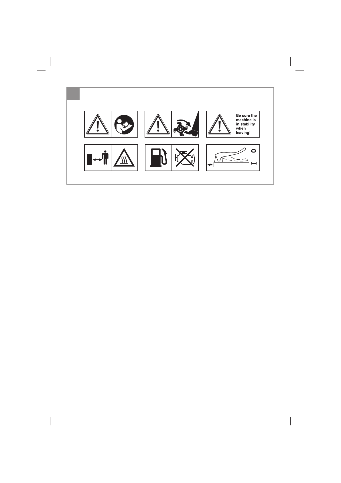
Erklärung des Hinweisschildes auf dem Gerät (siehe Bild 13)
1 Achtung! Bedienungsanleitung lesen. Warn-
und Sicherheitshinweise befolgen.
2 Achtung! Verletzungsgefahr durch rotierende
Teile. Halten Sie Hände, Füße und Kleidung
fern.
3 Achten Sie auf sicheren Stand der Maschine
wenn Sie diese verlassen.
4 Achtung! Heisse Teile. Abstand halten.
5 Achtung! Während des Tankens Motor abstel-
len.
6 Beschreibung Kupplungshebel: 0 = Hack-
messer Stop; 1 = Hackmesser Ein
2. Gerätebeschreibung und
Lieferumfang
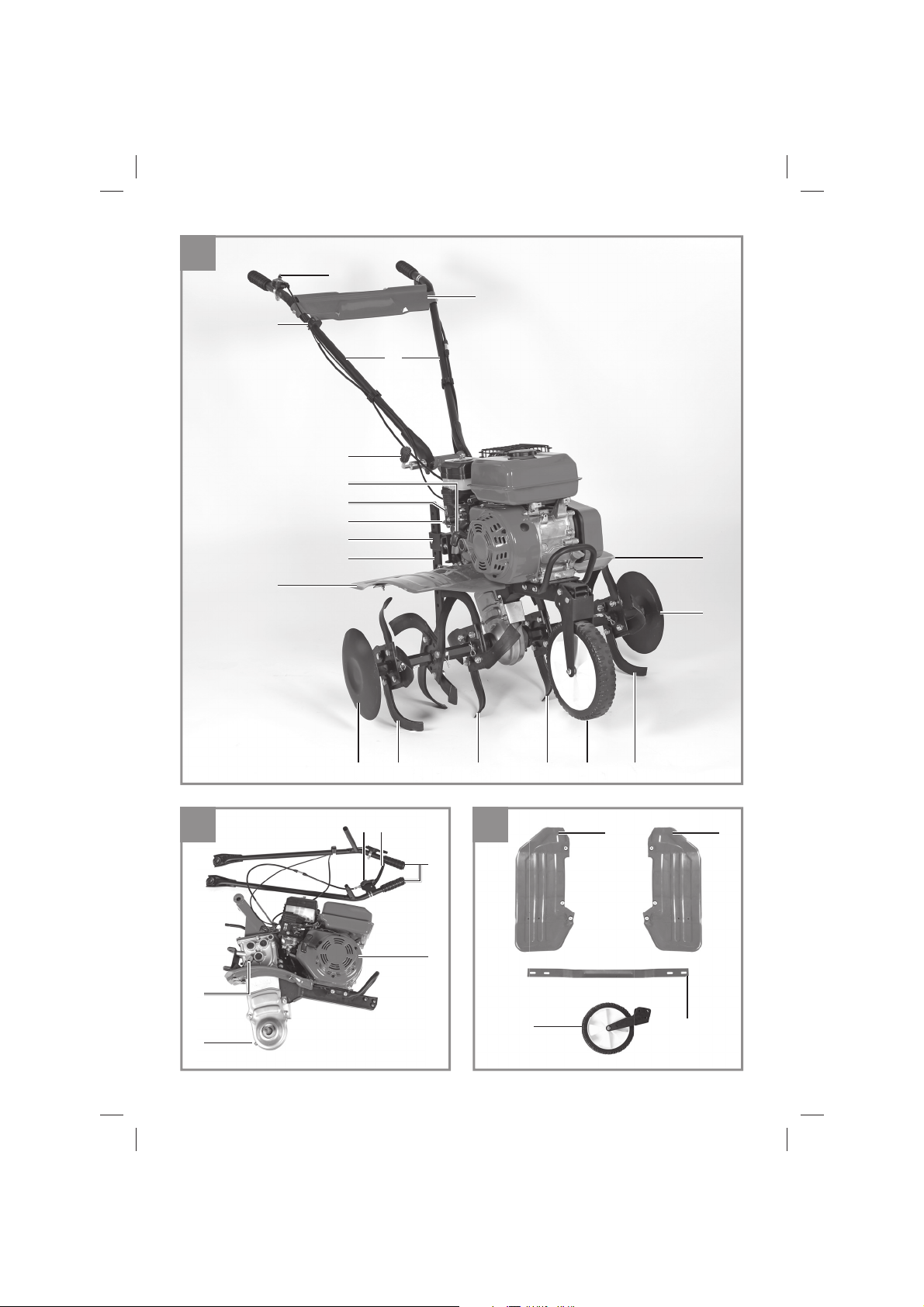
2.1 Gerätebeschreibung
1. Motor-/ Getriebeeinheit
2. Reversierstarter
3. Zündkerzenschlüssel (nicht abgebildet)
4a. Kupplungshebel
4b. Sicherungshebel
4c. Start/Stopp – Schalter
4d. Gashebel
4e. Chokehebel
5. Benzinhahn
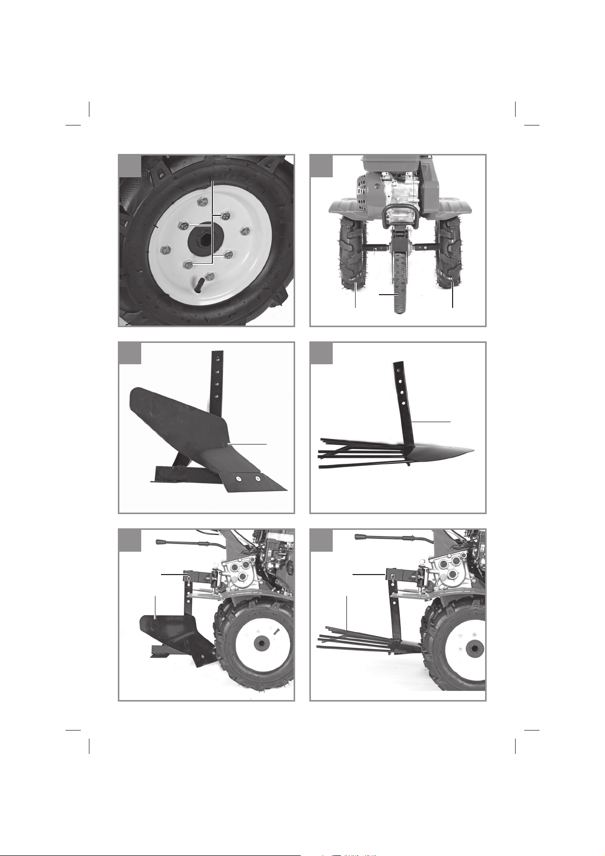
Montageset für Schutzblech / Transportrad
(Abb. 3a - 3e):
6. Transportrad
7. 1x Schraube M10x80
8. 1x Kronenmutter M10
9. 1x Bolzen Ø10x70
10. 2x Sicherungssplint klein
11. Schutzblech links
12. Schutzblech rechts
13. Schutzblech Verbindungsstrebe
14. 10x Schraube M6×20
15. 10x Sicherungsmutter M6
16. 14x Unterlegscheibe Ø6
Montageset für Hackmesser / Tiefenanschlag
(Abb. 4a - 4e):
17. Hackmesser rechts innen
18. Hackmesser rechts außen
19. Hackmesser links innen
20. Hackmesser links außen
21. 2x Begrenzungsscheibe
22. 7x Bolzen Ø8x40
23. 7x Sicherungssplint klein
24. Halterung Tiefenanschlag / Anbaugeräte
25. Tiefenanschlag
26. 1x Bolzen Ø16 x 111
27. 1x Sicherungssplint groß
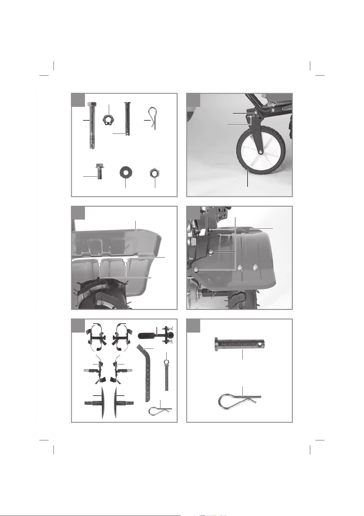
Montageset für Fahrbügel / Schalthebel (Abb.
5a - 5f):
30. Schalthebel
31. 1x Schraube M6×25
32. 1x Sicherungsmutter M6
33. Fahrbügel
34. Griff Höhenverstellung
35. 1x Schraube M16×160
36. 1x Federring Ø16
37. 1x Unterlegscheibe
38. Abdeckblech Fahrbügel
39. 1x Schraube M8x35
40. 1x Sicherungsmutter M8
41. 2x Schraube M6×35
42. 2x Sicherungsmutter M6
43. 2x Kabelclip
- 10 -
Anl_GC_MT_4280_SPK13.indb 10Anl_GC_MT_4280_SPK13.indb 10 20.09.2021 11:29:1320.09.2021 11:29:13

D
Montageset Räder (Abb. 11a – 11f)
44. 2x Räder
45. 2x Nabe
46. 8x Schraube M 10x25
47. 8x Mutter M10
48. 8x Federring Ø10
Zubehör (Abb.12a – 12d nicht im Lieferumfang enthalten)
49. Pfl ug (nicht im Lieferumfang enthalten)
50. Kartoff elpfl ug (nicht im Lieferumfang enthal-
ten)
2.2 Lieferumfang
Bitte überprüfen Sie die Vollständigkeit des Artikels anhand des beschriebenen Lieferumfangs.
Bei Fehlteilen wenden Sie sich bitte spätestens
innerhalb von 5 Arbeitstagen nach Kauf des Artikels unter Vorlage eines gültigen Kaufbeleges an
unser Service Center oder an die Verkaufstelle,
bei der Sie das Gerät erworben haben. Bitte
beachten Sie hierzu die Gewährleistungstabelle
in den Service-Informationen am Ende der Anleitung.
Öffnen Sie die Verpackung und nehmen Sie
•
das Gerät vorsichtig aus der Verpackung.
Entfernen Sie das Verpackungsmaterial so-
•
wie Verpackungs-/ und Transportsicherungen
(falls vorhanden).
Überprüfen Sie, ob der Lieferumfang vollstän-
•
dig ist.
Kontrollieren Sie das Gerät und die Zubehör-
•
teile auf Transportschäden.
Bewahren Sie die Verpackung nach Möglich-
•
keit bis zum Ablauf der Garantiezeit auf.
Gefahr!
Gerät und Verpackungsmaterial sind kein
Kinderspielzeug! Kinder dürfen nicht mit
Kunststoff beuteln, Folien und Kleinteilen
spielen! Es besteht Verschluckungs- und Erstickungsgefahr!
Originalbetriebsanleitung
•
Sicherheitshinweise
•
Die Maschine darf nur nach ihrer Bestimmung
verwendet werden. Jede weitere darüber hinausgehende Verwendung ist nicht bestimmungsgemäß. Für daraus hervorgerufene Schäden oder
Verletzungen aller Art haftet der Benutzer/Bediener und nicht der Hersteller.
Bitte beachten Sie, dass unsere Geräte bestimmungsgemäß nicht für den gewerblichen, handwerklichen oder industriellen Einsatz konstruiert
wurden. Wir übernehmen keine Gewährleistung,
wenn das Gerät in Gewerbe-, Handwerks- oder
Industriebetrieben sowie bei gleichzusetzenden
Tätigkeiten eingesetzt wird.
4. Technische Daten
Motor: ......................................... 4-Takt, 212 cm
Motorleistung: ........................... 4,1 kW/ (5,5 PS)
Arbeitsdrehzahl Motor: ........................ 3600 min
Arbeitsbreite: ..............................................89 cm
Hackmesser Ø: ..........................................36 cm
Vorwärtsgang: ................................................... 2
Startsystem: .................Reversierstarteinrichtung
Kraftstoff : .........................................Benzin (E10)
Motoröl (Motor): .......................................ca.0,5 l
Motoröl (Getriebe): ...................................... ca.1 l
Motoröl (Luftfi lter): ................................ca.0,045 l
Tankinhalt: ............................................... ca. 3,6 l
Vibration ahv: ............................................6,8 m/s
Unsicherheit K:.........................................1,5 m/s2
Gewicht: ......................................................69 kg
Zündkerze: ............................................... F6RTC
Schalldruckpegel L
Unsicherheit K
Garantierter Schallleistungspegel L
........................... 81,8 dB(A)
pA
............................................ 3 dB
pA
.... 99 dB(A)
WA
5. Vor Inbetriebnahme
Hinweis: Zur Montage sind zwei Personen
notwendig!
3
-1
2
3. Bestimmungsgemäße
Verwendung
Das Gerät ist geeignet zum Umgraben von
Beeten und Ackern. Beachten Sie unbedingt die
Einschränkungen in den zusätzlichen Sicherheitshinweisen.
Anl_GC_MT_4280_SPK13.indb 11Anl_GC_MT_4280_SPK13.indb 11 20.09.2021 11:29:1320.09.2021 11:29:13
Montage Schutzblech und Transportrad
1. Legen Sie sich die Bauteile wie unter Punkt
2.1 Lieferumfang beschrieben zurecht.
2. Transportrad (6) an Motor-/Getriebeeinheit (1)
wie in Abb. 3c gezeigt montieren.
3. Schutzblech (4) und Verbindungsstrebe (13)
wie in Abb. 3d/3e gezeigt montieren.
- 11 -

D
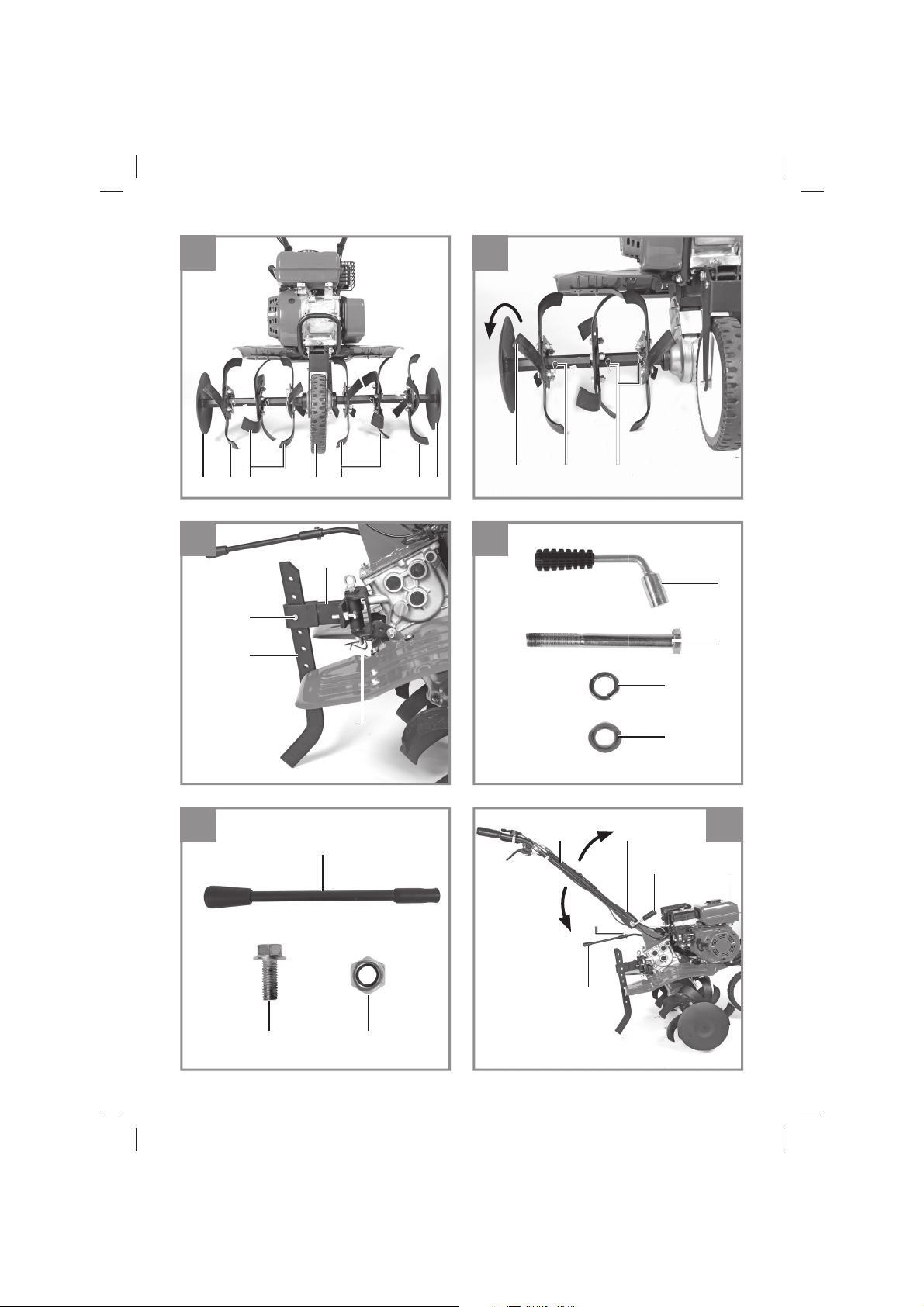
Montage Hackmesser und Tiefenanschlag
1. Legen Sie sich die Bauteile wie unter Punkt
2.1 Lieferumfang beschrieben zurecht.
2. Hackmesser rechts (17/18), Hackmesser
links (19/20) und Begrenzungsscheiben (21)
wie in Abb. 4c/4d gezeigt montieren. Beachten Sie dabei, dass die scharfe Seite des
Hackmessers (Abb. 4d/Pos. A) in Drehrichtung zeigt.
3. Tiefenanschlag (24/25) wie in Abb. 4e gezeigt
montieren und mit Sicherungssplint in Position sichern. Zu Arbeitsbeginn empfehlen wir
den Tiefenanschlag in mittlerer der 8 möglichen Positionen zu fi xieren. Soll die Arbeits-
tiefe verändert werden, verschieben Sie die
Position des Tiefenanschlags nach oben oder
unten.
Montage Fahrbügel und Schalthebel
1. Legen Sie sich die Bauteile wie unter Punkt
2.1 Lieferumfang beschrieben zurecht.
2. Fahrbügel (33) und Schalthebel (30) wie in
Abb. 5c gezeigt montieren.
3. Abdeckblech Fahrbügel (38) und Kabelclip
(43) wie in Abb. 5f gezeigt montieren.
Montage Räder
1. Legen Sie sich die Bauteile wie unter Punkt
2.1 Lieferumfang beschrieben zurecht.
2. 2. Räder (44) und Nabe (45) wie in Abb. 11a11f gezeigt montieren.
Achtung! Bei Erstbetriebnahme muss Motorenöl
und Kraftstoff eingefüllt werden (7.2).
Kraftstoff- und Motorenölstand prüfen, even-
•
tuell nachfüllen.
Luftfilter mit Öl befüllen (7.2)
•
Getriebe mit Öl befüllen (7.2)
•
Vergewissern Sie sich, dass das Zündkabel
•
an der Zündkerze befestigt ist
Die unmittelbare Umgebung der Motorhacke
•
begutachten
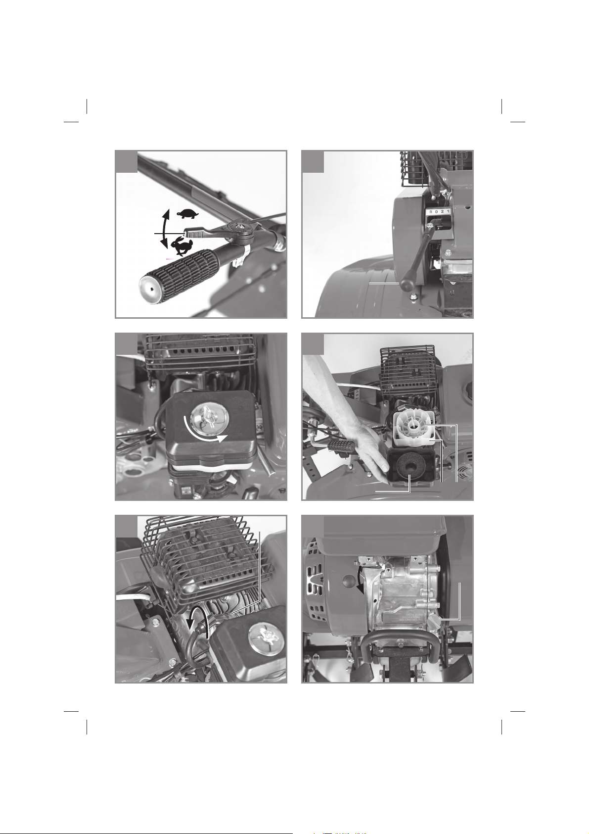
6. Bedienung
Tiefenanschlag (Abb. 4e / Pos. 25) auf richtige
•
Höhe einstellen und mit Splint sichern.
Transportrad nach oben schwenken und da-
•
rauf achten, dass der Bolzen der Rasterung
in der Aufnahme nach vorne eingerastet ist
(Abb.6a).
Je nach Körpergröße können Sie die Fahrbü-
•
gel einstellen. Dazu den Griff Höhenverstel-
lung (Abb. 5c) lösen, Konsole einstellen und
Schrauben wieder festziehen.
Um die Hacksterne in Betrieb zu setzen,
•
den Sicherungshebel 4b betätigen, den
Kupplungshebel 4a ziehen und halten (Abb.
6b). Nach Loslassen des Kupplungshebels
bleiben die Hacksterne stehen (falls diese
nicht stehen bleiben sollten, Kupplungsseil
nachstellen 7.2.4).
Zum Wechseln der Getriebeschaltstufe las-
•
sen Sie den Kupplungshebel (4a) los, das
Getriebe ist vom Motor entkoppelt. Legen Sie
die gewünschte Schaltstufe mit dem Schalthebel (30) ein (Abb. 7c):
R = Rückwärts
0 = Leerlauf
2 = 2. Gang
1 = 1. Gang
Warnung! Verletzungsgefahr beim Rückwärtsfahren! Die Maschine bewegt sich auf
den Bediener zu.
Motor Starten
Vergewissern Sie sich, dass das Zündkabel
•
an der Zündkerze angeschlossen ist.
Benzinhahn (5) öffnen.
•
Start/Stopp – Schalter (4c) auf Stellung “ON”
•
bringen
Chokehebel (4e) auf Stellung IØI bringen
•
Den Motor mit dem Reversierstarter (2) star-
•
ten; hierfür am Griff kräftig anziehen. Sollte
der Motor nicht gestartet haben, nochmals
am Griff anziehen
Chokehebel (4e) nach dem Starten des Mo-
•
tors wieder zurückschieben.
Gashebel (4d) in Position bringen für ge-
•
wünschte Drehzahl.
Achtung!
Beim Starten mit dem Reversierstarter kann es
durch plötzlichen Rückschlag, verursacht durch
den anlaufenden Motor, zu Verletzungen an der
Hand kommen. Tragen Sie zum Starten Schutzhandschuhe.
Hinweis! Den Seilzug nicht zurückschleudern
lassen.
Hinweis! Bei kühlem Wetter kann es erforderlich
sein, den Anlassvorgang mehrmals zu wiederholen.
- 12 -
Anl_GC_MT_4280_SPK13.indb 12Anl_GC_MT_4280_SPK13.indb 12 20.09.2021 11:29:1320.09.2021 11:29:13

D
Motor Stoppen
Stellen Sie den Motor Start/Stopp - Hebel (4c) in
Position STOP.
7. Reinigung, Wartung, Lagerung
und Ersatzteilbestellung
Gefahr!
Ziehen Sie vor allen Reinigungs- und Wartungsarbeiten den Zündkerzenstecker.
7.1 Reinigung
Halten Sie Schutzvorrichtungen, Luftschlitze
•
und Motorengehäuse so staub- und schmutzfrei wie möglich. Reiben Sie das Gerät mit
einem sauberen Tuch ab oder blasen Sie es
mit Druckluft bei niedrigem Druck aus.
Wir empfehlen, dass Sie das Gerät direkt
•
nach jeder Benutzung reinigen.
Reinigen Sie das Gerät regelmäßig mit einem
•
feuchten Tuch und etwas Schmierseife. Verwenden Sie keine Reinigungs- oder Lösungsmittel; diese könnten die Kunststoffteile des
Gerätes angreifen. Achten Sie darauf, dass
kein Wasser in das Geräteinnere gelangen
kann.
7.2 Wartung
Achtung: Stellen Sie das Gerät sofort ab und
wenden Sie sich an ihren autorisierten Fachhändler:
Bei ungewöhnlichen Schwingungen oder Ge-
•
räuschen.
Wenn der Motor überlastet scheint, oder
•
Fehlzündungen hat.
Weitere Informationen entnehmen Sie dem
•
Punkt 4. Technische Daten und Serviceheft
für Benzingeräte.
7.2.1 Luftfi lter warten
Luftfilter und Filteröl vor jedem Gebrauch prü-
•
fen, Luftfilter reinigen, wenn nötig tauschen.
Entnehmen Sie das Filterelement (Abb. 8a-
•
8b).
Zum Reinigen des Elementes dürfen keine
•
scharfen Reiniger oder Benzin verwendet
werden. Ist das Filterelement stark mit Öl vollgesogen, drücken Sie das Öl heraus.
Bei starker Verschmutzung oder Beschädi-
•
gung ersetzen Sie das Filterelement (A).
Füllen Sie Motorenöl in den Luftfilterkasten
•
(B) bis zur Markierung (C). Bitte achten Sie
darauf das Arbeitsgerät nicht mehr übermä-
ßig zu kippen, es würde Öl aus dem Luftfilterkasten auslaufen.
Der Zusammenbau erfolgt in umgekehrter
•
Reihenfolge.
7.2.2 Zündkerze warten
Überprüfen Sie die Zündkerze erstmals nach 10
Betriebsstunden auf Verschmutzung und reinigen
Sie diese gegebenenfalls mit einer Kupferdrahtbürste. Danach die Zündkerze alle 50 Betriebsstunden warten.
Ziehen Sie den Zündkerzenstecker (Abb. 9)
•
mit einer Drehbewegung ab.
Entfernen Sie die Zündkerze (Abb. 9/Pos.D)
•
mit dem beiliegendem Zündkerzenschlüssel.
Der Zusammenbau erfolgt in umgekehrter
•
Reihenfolge.
7.2.3 Benzinmotor Ölwechsel/ Ölstand prüfen
(vor jedem Gebrauch)
Der Motorölwechsel sollte bei betriebswarmem
Motor durchgeführt werden.
Ölmessstab (Abb. 10a / Pos.E) und Ölablass-
•
schraube (Abb. 10b / Pos.F) herausnehmen.
Warmes Motoröl in einen Auffangbehälter
•
ablassen.
Motoröl bis zur oberen Markierung des Öl-
•
messstabes (Abb. 10c/H) einfüllen.
Achtung Ölmessstab zum Ölstandprüfen
•
nicht einschrauben, sondern nur bis zum Gewinde einstecken (H = Max. / L= Min.).
Das Altöl muss ordentlich entsorgt werden.
•
7.2.4 Einstellen der Bowdenzüge
In der Arbeitsstellung soll der Kupplungshebel
mit geringem Kraftaufwand bis zum Schubbügel hinabgedrückt werden können. Wenn der
Bowdenzug dabei zu straff gespannt ist, muss
dieser länger eingestellt werden. Dazu lösen Sie
die Kontermutter gegenüber dem Hauptseilzug,
verlängern die Schraubenverbindung und ziehen
anschließend die Kontermutter wieder fest (siehe
Abb. 6b/Pos. G). Falls die Hacksterne nicht mehr
rotieren, muss die Schraubenverbindung (analog
wie vorher beschrieben) verkürzt werden.
7.2.5 Getriebe der Motorhacke Ölwechsel/auf
Ölverlust prüfen (Sichtprüfung vor jedem
Gebrauch)
Der Ölwechsel sollte bei betriebswarmem Getriebe durchgeführt werden. Erstmalig nach einer
Betriebszeit von 20h, danach alle 50h.
Ölverschlussdeckel Abb.2 (G) und Ölablass-
•
schraube Abb.2 (E) öffnen. Warmes Öl in
einen Auffangbehälter ablassen.
- 13 -
Anl_GC_MT_4280_SPK13.indb 13Anl_GC_MT_4280_SPK13.indb 13 20.09.2021 11:29:1420.09.2021 11:29:14

Öl auffüllen.
•
Das Altöl muss ordentlich entsorgt werden.
•
Der Antrieb des Getriebes erfolgt über einen
Keilriemen. Das Getriebe kann gegebenenfalls
repariert werden. Wenden Sie sich hierfür an den
Kundendienst.
7.3 Lagerung
Entleeren Sie den Kraftstoff tank bevor Sie das
Gerät für längere Zeit außer Betrieb nehmen.
Reinigen Sie das Gerät und benetzten Sie alle
Metallteile mit einem dünnen Ölfi lm, zum Schutz
vor Verrostung. Lagern Sie das Gerät in einem
sauberen und trockenen Raum.
7.4 Ersatzteilbestellung:
Bei der Ersatzteilbestellung sollten folgende Angaben gemacht werden;
Typ des Gerätes
•
Artikelnummer des Gerätes
•
Ident-Nummer des Gerätes
•
Ersatzteilnummer des erforderlichen Ersatz-
•
teils
Aktuelle Preise und Infos fi nden Sie unter
www.Einhell-Service.com
D
8. Entsorgung und
Wiederverwertung
Das Gerät befi ndet sich in einer Verpackung um
Transportschäden zu verhindern. Diese Verpackung ist Rohstoff und ist somit wieder verwend-
bar oder kann dem Rohstoff kreislauf zurückge-
führt werden. Das Gerät und dessen Zubehör
bestehen aus verschiedenen Materialien, wie
z.B. Metall und Kunststoff e. Defekte Geräte ge-
hören nicht in den Hausmüll. Zur fachgerechten
Entsorgung sollte das Gerät an einer geeigneten
Sammelstellen abgegeben werden. Wenn Ihnen
keine Sammelstelle bekannt ist, sollten Sie bei
der Gemeindeverwaltung nachfragen.
Der Nachdruck oder sonstige Vervielfältigung von
Dokumentation und Begleitpapieren der Produkte, auch auszugsweise, ist nur mit ausdrücklicher
Zustimmung der Einhell Germany AG zulässig.
Technische Änderungen vorbehalten
- 14 -
Anl_GC_MT_4280_SPK13.indb 14Anl_GC_MT_4280_SPK13.indb 14 20.09.2021 11:29:1420.09.2021 11:29:14

D
9. Fehlersuchplan
Warnhinweis: Zuerst den Motor abschalten und den Zündkerzenstecker abziehen, bevor Inspektionen
oder Justierungen vorgenommen werden.
Warnhinweis: Wenn nach einer Justierung oder Reparatur der Motor einige Minuten gelaufen ist, denken Sie daran, dass der Auspuff und andere Teile heiß sind. Also nicht berühren, um Verbrennungen zu
vermeiden.
Störung Mögliche Ursache Behebung
Unruhiger Lauf,
starkes Vibrieren
des Gerätes
Motor läuft nicht - Zündkerze defekt
Motor läuft unruhig - Luftfi lter verschmutzt
Antriebskraft lässt
nach
Motor kann nicht
gestartet werden
oder stirbt nach kurzer Zeit ab
- Schrauben lose
- Zündkerze defekt
- Kraftstoff tank leer
- Zündkerze verschmutzt, defekt
- Kupplungsspiel zu groß
- Keilriemen lose
- Zündkerze verrußt
- kein Kraftstoff
- Schrauben prüfen
- Zündkerze erneuern
- Zündkerze erneuern
- Kraftstoff einfüllen
- Luftfi lter reinigen
- Zündkerze reinigen, erneuern
- Kupplungsseil einstellen
- Autorisierten Kundendienst aufsuchen
- Zündkerze reinigen
- Kraftstoff nachfüllen
- 15 -
Anl_GC_MT_4280_SPK13.indb 15Anl_GC_MT_4280_SPK13.indb 15 20.09.2021 11:29:1420.09.2021 11:29:14

D
Service-Informationen
Wir unterhalten in allen Ländern, welche in der Garantieurkunde benannt sind, kompetente ServicePartner, deren Kontakte Sie der Garantieurkunde entnehmen. Diese stehen Ihnen für alle ServiceBelange wie Reparatur, Ersatzteil- und Verschleißteil-Versorgung oder den Bezug von Verbrauchsmaterialien zur Verfügung.
Es ist zu beachten, dass bei diesem Produkt folgende Teile einem gebrauchsgemäßen oder natürlichen
Verschleiß unterliegen bzw. folgende Teile als Verbrauchsmaterialien benötigt werden.
Kategorie Beispiel
Verschleißteile* Zündkerze, Luftfi lter, Hackmesser, Keilriemen,
Verbrauchsmaterial/ Verbrauchsteile*
Fehlteile
* nicht zwingend im Lieferumfang enthalten!
Bei Mängel oder Fehlern bitten wir Sie, den Fehlerfall im Internet unter www.Einhell-Service.com anzumelden. Bitte achten Sie auf eine genaue Fehlerbeschreibung und beantworten Sie dazu in jedem Fall
folgende Fragen:
Hat das Gerät bereits einmal funktioniert oder war es von Anfang an defekt?
•
Ist Ihnen vor dem Auftreten des Defektes etwas aufgefallen (Symptom vor Defekt)?
•
Welche Fehlfunktion weist das Gerät Ihrer Meinung nach auf (Hauptsymptom)?
•
Beschreiben Sie diese Fehlfunktion.
Kupplung, Kraftstoff fi lter
- 16 -
Anl_GC_MT_4280_SPK13.indb 16Anl_GC_MT_4280_SPK13.indb 16 20.09.2021 11:29:1420.09.2021 11:29:14

D
Garantieurkunde
Sehr geehrte Kundin, sehr geehrter Kunde,
unsere Produkte unterliegen einer strengen Qualitätskontrolle. Sollte dieses Gerät dennoch einmal nicht
einwandfrei funktionieren, bedauern wir dies sehr und bitten Sie, sich an unseren Servicedienst unter
der auf dieser Garantiekarte angegebenen Adresse zu wenden. Gerne stehen wir Ihnen auch telefonisch über die angegebene Servicerufnummer zur Verfügung. Für die Geltendmachung von Garantieansprüchen gilt folgendes:
1. Diese Garantiebedingungen richten sich ausschließlich an Verbraucher, d. h. natürliche Personen,
die dieses Produkt weder im Rahmen ihrer gewerblichen noch anderen selbständigen Tätigkeit
nutzen wollen. Diese Garantiebedingungen regeln zusätzliche Garantieleistungen, die der u. g.
Hersteller zusätzlich zur gesetzlichen Gewährleistung Käufern seiner Neugeräte verspricht. Ihre
gesetzlichen Gewährleistungsansprüche werden von dieser Garantie nicht berührt. Unsere Garantieleistung ist für Sie kostenlos.
2. Die Garantieleistung erstreckt sich ausschließlich auf Mängel an einem von Ihnen erworbenen neuen Gerät des u. g. Herstellers, die auf einem Material- oder Herstellungsfehler beruhen und ist nach
unserer Wahl auf die Behebung solcher Mängel am Gerät oder den Austausch des Gerätes beschränkt. Bitte beachten Sie, dass unsere Geräte bestimmungsgemäß nicht für den gewerblichen,
handwerklichen oder berufl ichen Einsatz konstruiert wurden. Ein Garantievertrag kommt daher nicht
zustande, wenn das Gerät innerhalb der Garantiezeit in Gewerbe-, Handwerks- oder Industriebetrieben verwendet wurde oder einer gleichzusetzenden Beanspruchung ausgesetzt war.
3. Von unserer Garantie ausgenommen sind:
- Schäden am Gerät, die durch Nichtbeachtung der Montageanleitung oder aufgrund nicht fachgerechter Installation, Nichtbeachtung der Gebrauchsanleitung (wie durch z.B. Anschluss an eine
falsche Netzspannung oder Stromart) oder Nichtbeachtung der Wartungs- und Sicherheitsbestimmungen oder durch Aussetzen des Geräts an anomale Umweltbedingungen oder durch mangelnde
Pfl ege und Wartung entstanden sind.
- Schäden am Gerät, die durch missbräuchliche oder unsachgemäße Anwendungen (wie z.B. Überlastung des Gerätes oder Verwendung von nicht zugelassenen Einsatzwerkzeugen oder Zubehör),
Eindringen von Fremdkörpern in das Gerät (wie z.B. Sand, Steine oder Staub, Transportschäden),
Gewaltanwendung oder Fremdeinwirkungen (wie z. B. Schäden durch Herunterfallen) entstanden
sind.
- Schäden am Gerät oder an Teilen des Geräts, die auf einen gebrauchsgemäßen, üblichen oder
sonstigen natürlichen Verschleiß zurückzuführen sind.
4. Die Garantiezeit beträgt 24 Monate und beginnt mit dem Kaufdatum des Gerätes. Garantieansprüche sind vor Ablauf der Garantiezeit innerhalb von zwei Wochen, nachdem Sie den Defekt erkannt
haben, geltend zu machen. Die Geltendmachung von Garantieansprüchen nach Ablauf der Garantiezeit ist ausgeschlossen. Die Reparatur oder der Austausch des Gerätes führt weder zu einer
Verlängerung der Garantiezeit noch wird eine neue Garantiezeit durch diese Leistung für das Gerät
oder für etwaige eingebaute Ersatzteile in Gang gesetzt. Dies gilt auch bei Einsatz eines Vor-OrtServices.
5. Für die Geltendmachung Ihres Garantieanspruches melden Sie bitte das defekte Gerät an unter:
www.Einhell-Service.com. Halten Sie bitte den Kaufbeleg oder andere Nachweise Ihres Kaufs des
Neugeräts bereit. Geräte, die ohne entsprechende Nachweise oder ohne Typenschild eingesendet
werden, sind von der Garantieleistung aufgrund mangelnder Zuordnungsmöglichkeit ausgeschlossen. Ist der Defekt des Gerätes von unserer Garantieleistung erfasst, erhalten Sie umgehend ein
repariertes oder neues Gerät zurück.
Selbstverständlich beheben wir gegen Erstattung der Kosten auch gerne Defekte am Gerät, die vom
Garantieumfang nicht oder nicht mehr erfasst sind. Dazu senden Sie das Gerät bitte an unsere Serviceadresse.
Für Verschleiß-, Verbrauchs- und Fehlteile verweisen wir auf die Einschränkungen dieser Garantie gemäß den Service-Informationen dieser Bedienungsanleitung.
Einhell Service · Eschenstraße 6 · 94405 Landau/Isar (Deutschland)
- 17 -
Anl_GC_MT_4280_SPK13.indb 17Anl_GC_MT_4280_SPK13.indb 17 20.09.2021 11:29:1520.09.2021 11:29:15

D
Sehr geehrte Kundin,
sehr geehrter Kunde,
LIEBE MÖGLICHMACHER,
wir haben das Ziel, alles dafür zu tun, damit Sie mit Einhell all Ihre Projekte möglich machen können. Aus diesem
Grund ist Service bei uns gelebter Anspruch: mit über 20 Jahren Erfahrung und mehr als 120 kompetenten und
persönlichen Ansprechpar tnern hat es sich der Einhell Service auf die Fahnen geschrieben, Sie bei allen Fragen
zu Ihrem Produkt zu unterstützen. Dazu gehört ein beratendes Techniker team, bis zu 10 Jahre Ersatzteilverfügbarkeit, 24 Stunden Versandservice, eine leistungsfähige Reparatur-Organisation und ein fl ächendeckendes
Service-Partnernetz.
Über unser Onlineportal www.Einhell-Service.com sind viele unserer verfügbaren Services jetzt noch
schneller und einfacher für Sie erreichbar – rund um die Uhr, sieben Tage die Woche.
ERSATZTEILE
PREISINFORMATIONEN
GARANTIEVERLÄNGERUNGEN
Einhell Service
Eschenstraße 6
944 05 Landau an der Isar
ZUBEHÖR
VERFÜGBARKEITEN
REPARATURSERVICE
Telefon: 09951 - 959 2000
Telefax: 09951 - 959 1700
E-Mail: Service-DE@Einhell.com
Wir freuen uns auf Ihren Besuch unter
PRODUKTINFORMATIONEN
TRACK & TRACE
SERVICE-STELLEN
VOR ORT
Einhell-Service.com
>>>
- 18 -
Anl_GC_MT_4280_SPK13.indb 18Anl_GC_MT_4280_SPK13.indb 18 20.09.2021 11:29:1520.09.2021 11:29:15

GB
Danger!
When using the equipment, a few safety precautions must be observed to avoid injuries and
damage. Please read the complete operating
instructions and safety regulations with due care.
Keep this manual in a safe place, so that the information is available at all times. If you give the
equipment to any other person, hand over these
operating instructions and safety regulations as
well. We cannot accept any liability for damage
or accidents which arise due to a failure to follow
these instructions and the safety instructions.
1. Safety regulations
The corresponding safety information can be
found in the enclosed booklet.
Warning!
Read all the safety information, instructions,
illustrations and technical data provided on
or with this power tool. Failure to adhere to the
following instructions may result in electric shock,
fi re and/or serious injury.
Keep all the safety information and instructions in a safe place for future use.
Explanation of the warning signs on the
equipment (see Fig. 13)
1 Important! Read the operating instructions.
Follow the warnings and safety instructions.
2 Important! Risk of injury from rotating parts.
Keep your hands, feet and clothing away from
these parts.
3 Always make sure that the machine is stan-
ding solidly whenever you leave it.
4 Important! Hot parts. Keep your distance.
5 Important! Switch off the engine before refue-
ling.
6 Description of the clutch lever: 0 = Tiller blade
stop; 1 = Tiller blade On
2. Layout and items supplied
2.1 Layout
1. Engine / gear unit
2. Reversing starter
3. Spark plug wrench (not illustrated)
4a. Clutch lever
4b. Safety lever
4c. Start/Stop switch
4d. Throttle lever
4e. Choke lever
5. Petrol cock
Assembly set for guard plate / transport
wheel (Fig. 3a - 3e):
6. Transport wheel
7. 1x Screw, M10x80
8. 1x Castle nut, M10
9. 1x Bolt, Ø10x70
10. 2x Split pin, small
11. Guard plate, left
12. Guard plate, right
13. Guard plate for connecting strut
14. 10x Screw, M6×20
15. 10x Locknut, M6
16. 14x Washer, Ø6
Assembly set for cultivator blades / depth
stop (Fig. 4a - 4e):
17. Cultivator blade, inside on the right
18. Cultivator blade, outside on the right
19. Cultivator blade, inside on the left
20. Cultivator blade, outside on the left
21. 2x Limiting disc
22. 7x Bolt, Ø8x40
23. 7x Split pin, small
24. Holder for depth stop / attachments
25. Depth stop
26. 1x Bolt, Ø16 x 111
27. 1x Split pin, large
Assembly set for steering handle / selector
lever (Fig. 5a - 5f):
30. Selector lever
31. 1x Screw, M6×25
32. 1x Locknut, M6
33. Steering handle
34. Handle for height adjustment
35. 1x Screw, M16×160
36. 1x Spring washer, Ø16
37. 1x Washer
38. Cover plate for steering handle
39. 1x bolt M8x35
40. 1x Locknut, M8
41. 2x Screw, M6×35
42. 2x Locknut, M6
43. 2x Cable clip
Assembly set for wheels (Fig. 11a – 11f)
44. 2x Wheel
45. 2x Hub
46. 8x Screw, M10x25
47. 8x Nut, M10
48. 8x Spring washer, Ø10
- 19 -
Anl_GC_MT_4280_SPK13.indb 19Anl_GC_MT_4280_SPK13.indb 19 20.09.2021 11:29:4520.09.2021 11:29:45

GB
Accessories (Fig. 12a – 12d not included in
delivery)
49. Plow (not included in delivery)
50. Potato plow (not included in delivery)
2.2 Items supplied
Please check that the article is complete as
specifi ed in the scope of delivery. If parts are
missing, please contact our service center or the
sales outlet where you made your purchase at
the latest within 5 working days after purchasing
the product and upon presentation of a valid bill
of purchase. Also, refer to the warranty table in
the service information at the end of the operating
instructions.
Open the packaging and take out the equip-
•
ment with care.
Remove the packaging material and any
•
packaging and/or transportation braces (if
available).
Check to see if all items are supplied.
•
Inspect the equipment and accessories for
•
transport damage.
If possible, please keep the packaging until
•
the end of the guarantee period.
Danger!
The equipment and packaging material are
not toys. Do not let children play with plastic
bags, foils or small parts. There is a danger of
swallowing or suff ocating!
Original operating instructions
•
Safety instructions
•
3. Proper use
The equipment is designed for digging garden
beds and fi elds. Be sure to observe the restric-
tions in the additional safety instructions.
The equipment is to be used only for its prescribed purpose. Any other use is deemed to be a
case of misuse. The user / operator and not the
manufacturer will be liable for any damage or injuries of any kind caused as a result of this.
Please note that our equipment has not been designed for use in commercial, trade or industrial
applications. Our warranty will be voided if the
machine is used in commercial, trade or industrial
businesses or for equivalent purposes.
4. Technical data
Engine: .................................... 4-stroke, 212 cm
Engine rating: .......................... 4.1 kW / (5.5 HP)
Engine working speed: ........................3600 min
Working width: ............................................89 cm
Tiller blade diameter: .................................36 cm
Forward gear: ................................................... 2
Starting system: ....................... Reversing starter
Fuel: ..................................................Petrol (E10)
Engine oil (engine): .......................... approx. 0.5 l
Engine oil (gearing): ......................... approx. 1.0 l
Engine oil (air fi lter): .................... approx. 0.045 l
Tank capacity: ................................. approx. 3.6 l
Vibration ahv: ............................................6.8 m/s
Uncertainty K: .........................................1.5 m/s
Weight: ........................................................69 kg
Spark plug: ............................................... F6RTC
Sound pressure level L
Uncertainty K
Guaranteed sound power level L
............................................. 3 dB
pA
.................... 81.8 dB(A)
pA
....... 99 dB(A)
WA
5. Before starting the equipment
Note: Two persons are needed for assembly!
Assembling the guard plate and the transport
wheel
1. Arrange the components properly as described in section 2.1 Layout.
2. Fit the transport wheel (6) to the engine/gear
unit (1) as shown in Fig. 3c.
3. Fit the guard plate (4) and the connecting
strut (13) as shown in Fig. 3d/3e.
Assembling the cultivator blades and the
depth stop
1. Arrange the components properly as described in section 2.1 Layout.
2. Fit the right-hand cultivator blades (17/18),
the left-hand cultivator blades (19/20) and
the limiting discs (21) as shown in Fig. 4c/ 4d.
Make sure that the sharp side of the cultivator
blade (Fig. 4d/Item A) faces in the direction of
rotation.
3. Fit the depth stop (24/25) as shown in Fig. 4e
and secure in position with the split pin. We
recommend securing the depth stop in the
middle position of the 8 possible positions
when you begin your work. If you want to
3
-1
2
2
- 20 -
Anl_GC_MT_4280_SPK13.indb 20Anl_GC_MT_4280_SPK13.indb 20 20.09.2021 11:29:4520.09.2021 11:29:45

GB
change the working depth, move the depth
stop by sliding it up or down.
Assembling the steering handle and the selector lever
1. Arrange the components properly as described in section 2.1 Layout.
2. Fit the steering handle (33) and the selector
lever (30) as shown in Fig. 5c.
3. Fit the steering handle (38) and the cable clip
(43) as shown in Fig. 5f.
Assembling the wheels
1. Arrange the components properly as described in section 2.1 Layout.
2. Fit the wheels (44) and the hub (45) as shown
in Fig. 11a- 11f.
Important! Before you start up for the fi rst time you
must fi ll in engine oil and fuel (7.2).
Check the fuel and engine oil levels and top
•
up if required.
Fill the air filter with oil (7.2).
•
Fill the gearing with oil (7.2).
•
Make sure that the ignition cable is secured to
•
the spark plug.
Check the area immediately around the pow-
•
er cultivator.
6. Operation
Set the depth stop (Fig. 4e / Item 25) to the
•
desired depth and secure with the split pin.
Swing up the transport wheel and make sure
•
that the bolt of the latch is engaged in the
mount at the front (Fig. 6a).
You can adjust the steering handle to your
•
physical size. To do so, loosen the handle for
height adjustment (Fig. 5c), adjust the bracket
and retighten the screws.
To start the star-type hoes, actuate the safety
•
lever 4b, and press and hold the clutch lever
4a (Fig. 6b). Releasing the clutch lever will
bring the star-type hoes to a stop (if they do
not stop, readjust the clutch cable 7.2.4).
To change the gear setting, release the clutch
•
lever (4a) to disconnect the gearing from the
engine. Use the selector lever (30) to activate
the required gear setting (Fig. 7c):
R = Reverse
0 = Idle
2 = 2nd gear
1 = 1st gear
Warning! Risk of injury when reversing! The
machine moves towards the user.
Starting the engine
Ensure that the ignition cable is connected to
•
the spark plug.
Open the petrol cock (5).
•
Move the Start/Stop switch (4c) to the „ON“
•
position.
Move the choke lever (4e) to position IØI.
•
Start the engine with the reversing starter (2)
•
by pulling forcefully on the handle. If the engine does not start, pull the handle again.
Push the choke lever (4e) back again after
•
the engine has started.
Move the throttle lever (4d) into position for
•
the speed required.
Important!
When starting with the reversing starter, the engine might recoil suddenly as it starts up, resulting
in hand injuries. Wear protective gloves when
starting the equipment.
Important! Never allow the actuator cable to
snap back.
Important! In cold weather it might be necessary
to repeat the starting process several times.
Stopping the engine
Move the engine Start/Stop lever (4c) into the
STOP position.
7. Cleaning, maintenance, storage
and ordering of spare parts
Danger!
Pull out the spark plug boot before doing any
cleaning and maintenance work.
7.1 Cleaning
Keep all safety devices, air vents and the
•
motor housing free of dirt and dust as far as
possible. Wipe the equipment with a clean
cloth or blow it with compressed air at low
pressure.
We recommend that you clean the device
•
immediately each time you have finished
using it.
Clean the equipment regularly with a moist
•
cloth and some soft soap. Do not use
cleaning agents or solvents; these could at-
- 21 -
Anl_GC_MT_4280_SPK13.indb 21Anl_GC_MT_4280_SPK13.indb 21 20.09.2021 11:29:4520.09.2021 11:29:45

GB
tack the plastic parts of the equipment. Ensure that no water can seep into the device. The
ingress of water into an electric tool increases
the risk of an electric shock.
7.2 Maintenance
Important: Switch off the machine immedia-
tely and contact an authorized dealer in the
following cases:
In the event of unusual vibrations or noise.
•
If the engine appears to be overloaded or
•
misfires.
More information can be found in section 4
•
“Technical data and service manual for petrolpowered equipment”.
7.2.1 Air fi lter maintenance
Check the air filter and filter oil before every
•
use, clean the air filter, replace if necessary.
Remove the filter element (Fig. 8a-8b).
•
Do not use abrasive cleaning agents or petrol
•
to clean the element. If the filter element is
soaked with oil, squeeze the oil out.
Replace the filter element (A) if it is heavily
•
soiled or damaged.
Fill engine oil into the air filter box (B) up to
•
the mark (C). Take care not to tilt the machine
too much or oil will run out of the air filter box.
Assemble in reverse order.
•
7.2.2 Spark plug maintenance
Check the spark plug for dirt and grime after 10
hours of operation and if necessary clean it with
a copper wire brush. Thereafter service the spark
plug after every 50 hours of operation.
Pull off the spark plug boot (Fig. 9) with a
•
twist.
Remove the spark plug (Fig. 9/Item D) with
•
the supplied spark plug wrench.
Assemble in reverse order.
•
7.2.3 Changing the engine oil/checking the
engine oil level (before each use)
The engine oil is best changed when the engine
is at working temperature.
Remove the oil dip stick (Fig. 10a / Item E)
•
and the oil drain plug (Fig. 10b / Item F).
Drain the warm engine oil into a drip tray.
•
Fill in engine oil up to the top mark on the oil
•
dip stick (Fig. 10c/H).
Important: Do not screw in the dip stick when
•
you check the oil level, simply insert it as far
as the thread (H = Max. / L = Min.).
Dispose of the waste oil properly.
•
7.2.4 Adjusting the Bowden wires
In the working setting it should be possible to
push the clutch lever up to the push bar without
this requiring much eff ort. If the Bowden wire is
too taut for this, it must be extended. To do this,
undo the lock nut opposite the main cable, extend
the screw connector and then tighten the lock nut
again (see Fig. 6b/Item G). If the star-type hoes
no longer rotate, the screw connector will have to
be shortened (as described above).
7.2.5 Changing the gearing oil/checking for
oil loss from the gearing (visual check
before each use)
The oil is best changed when the gearing is at
working temperature. Carry out the fi rst oil change
after 20 hours in operation, then at regular intervals of 50 hours.
Open the oil cap (Fig. 2) (G) and the oil drain
•
plug (Fig. 2) (E). Drain the warm oil into a drip
tray.
Top up with oil.
•
Dispose of the waste oil properly.
•
The gear unit is driven by a V-belt. The gear unit
can be repaired if this should become necessary.
If repairs are necessary, please contact our customer service center.
7.3 Storage
Empty the fuel tank before you decommission the
machine for a lengthy period of time. Clean the
machine and coat all metal parts with a thin fi lm of
oil to protect them from rusting. Store the machine
in a clean, dry room.
7.4 Ordering replacement parts:
Please quote the following data when ordering
replacement parts:
Type of machine
•
Article number of the machine
•
Identification number of the machine
•
Replacement part number of the part required
•
For our latest prices and information please go to
www.Einhell-Service.com
- 22 -
Anl_GC_MT_4280_SPK13.indb 22Anl_GC_MT_4280_SPK13.indb 22 20.09.2021 11:29:4620.09.2021 11:29:46

8. Disposal and recycling
The equipment is supplied in packaging to prevent it from being damaged in transit. The raw
materials in this packaging can be reused or
recycled. The equipment and its accessories are
made of various types of material, such as metal
and plastic. Never place defective equipment in
your household refuse. The equipment should
be taken to a suitable collection center for proper
disposal. If you do not know the whereabouts of
such a collection point, you should ask in your
local council offi ces.
The reprinting or reproduction by any other means, in whole or in part, of documentation and
papers accompanying products is permitted only
with the express consent of the Einhell Germany
AG.
Subject to technical changes
GB
- 23 -
Anl_GC_MT_4280_SPK13.indb 23Anl_GC_MT_4280_SPK13.indb 23 20.09.2021 11:29:4620.09.2021 11:29:46

GB
9. Troubleshooting guide
Warning: Switch off the engine and pull out the ignition cable before making any checks or adjustments.
Warning: If, after making an adjustment or repair to the engine, you let it run for a few minutes, remem-
ber that the exhaust and other parts will get hot. Do not touch these parts as these may burn you.
Fault Possible causes Remedy
The unit does not
operate smoothly
and vibrates intensively
The engine does
not start
Engine does not run
smoothly
Drive power falls - Clutch play too large
The engine will not
start or dies after a
short period of time
- Bolts loose
- Spark plug defective
- Spark plug defective
- Fuel tank empty
- Air fi lter dirty
- Spark plug soiled or defective
- V-belt loose
- Spark plug foul
- No fuel
- Check bolts
- Replace spark plug
- Replace spark plug
- Top up fuel
- Clean the air fi lter
- Clean or replace the spark plug
- Adjust clutch cable
- Contact authorized customer service
- Clean or replace spark plug
- Top up fuel
- 24 -
Anl_GC_MT_4280_SPK13.indb 24Anl_GC_MT_4280_SPK13.indb 24 20.09.2021 11:29:4620.09.2021 11:29:46

GB
Ser vice information
We have competent service partners in all countries named on the guarantee certifi cate whose contact
details can also be found on the guarantee certifi cate. These partners will help you with all service re-
quests such as repairs, spare and wearing part orders or the purchase of consumables.
Please note that the following parts of this product are subject to normal or natural wear and that the
following parts are therefore also required for use as consumables.
Category Example
Wear parts* Spark plug, air fi lter, cultivator blade, V-belt, cou-
Consumables*
Missing parts
* Not necessarily included in the scope of delivery!
In the eff ect of defects or faults, please register the problem on the internet at www.Einhell-Service.com.
Please ensure that you provide a precise description of the problem and answer the following questions
in all cases:
Did the equipment work at all or was it defective from the beginning?
•
Did you notice anything (symptom or defect) prior to the failure?
•
What malfunction does the equipment have in your opinion (main symptom)?
•
Describe this malfunction.
pling, fuel fi lter
- 25 -
Anl_GC_MT_4280_SPK13.indb 25Anl_GC_MT_4280_SPK13.indb 25 20.09.2021 11:29:4720.09.2021 11:29:47

GB
Warranty certifi cate
Dear Customer,
All of our products undergo strict quality checks to ensure that they reach you in perfect condition. In the
unlikely event that your device develops a fault, please contact our service department at the address
shown on this guarantee card. You can also contact us by telephone using the service number shown.
Please note the following terms under which guarantee claims can be made:
1. These guarantee terms apply to consumers only, i.e. natural persons intending to use this product
neither for their commercial activities nor for any other self-employed activities. These warranty
terms regulate additional warranty services, which the manufacturer mentioned below promises to
buyers of its new products in addition to their statutory rights of guarantee. Your statutory guarantee
claims are not aff ected by this guarantee. Our guarantee is free of charge to you.
2. The warranty services cover only defects due to material or manufacturing faults on a product which
you have bought from the manufacturer mentioned below and are limited to either the rectifi cation of
said defects on the product or the replacement of the product, whichever we prefer.
Please note that our devices are not designed for use in commercial, trade or professional applications. A guarantee contract will not be created if the device has been used by commercial, trade or
industrial business or has been exposed to similar stresses during the guarantee period.
3. The following are not covered by our guarantee:
- Damage to the device caused by a failure to follow the assembly instructions or due to incorrect
installation, a failure to follow the operating instructions (for example connecting it to an incorrect
mains voltage or current type) or a failure to follow the maintenance and safety instructions or by exposing the device to abnormal environmental conditions or by lack of care and maintenance.
- Damage to the device caused by abuse or incorrect use (for example overloading the device or the
use or unapproved tools or accessories), ingress of foreign bodies into the device (such as sand,
stones or dust, transport damage), the use of force or damage caused by external forces (for example by dropping it).
- Damage to the device or parts of the device caused by normal or natural wear or tear or by normal
use of the device.
4. The guarantee is valid for a period of 24 months starting from the purchase date of the device. Guarantee claims should be submitted before the end of the guarantee period within two weeks of the
defect being noticed. No guarantee claims will be accepted after the end of the guarantee period.
The original guarantee period remains applicable to the device even if repairs are carried out or
parts are replaced. In such cases, the work performed or parts fi tted will not result in an extension
of the guarantee period, and no new guarantee will become active for the work performed or parts
fi tted. This also applies if an on-site service is used.
5. To make a claim under the guarantee, please register the defective device at:
www.Einhell-Service.com. Please keep your bill of purchase or other proof of purchase for the new
device. Devices that are returned without proof of purchase or without a rating plate shall not be
covered by the guarantee, because appropriate identifi cation will not be possible. If the defect is co-
vered by our guarantee, then the item in question will either be repaired immediately and returned to
you or we will send you a new replacement.
Of course, we are also happy off er a chargeable repair service for any defects which are not covered by
the scope of this guarantee or for units which are no longer covered. To take advantage of this service,
please send the device to our service address.
Also refer to the restrictions of this warranty concerning wear parts, consumables and missing parts as
set out in the service information in these operating instructions.
- 26 -
Anl_GC_MT_4280_SPK13.indb 26Anl_GC_MT_4280_SPK13.indb 26 20.09.2021 11:29:4720.09.2021 11:29:47

F
Danger !
Lors de l’utilisation d’appareils, il faut respecter
certaines mesures de sécurité afi n d’éviter des
blessures et dommages. Veuillez donc lire attentivement ce mode d’emploi/ces consignes de
sécurité. Veillez à le conserver en bon état pour
pouvoir accéder aux informations à tout moment.
Si l’appareil doit être remis à d’autres personnes,
veillez à leur remettre aussi ce mode d’emploi/
ces consignes de sécurité. Nous déclinons toute
responsabilité pour les accidents et dommages
dus au non-respect de ce mode d’emploi et des
consignes de sécurité.
1. Consignes de sécurité
Vous trouverez les consignes de sécurité correspondantes dans le cahier en annexe.
Avertissement !
Veuillez lire toutes les consignes de sécurité,
instructions, illustrations et caractéristiques
techniques de cet outil électrique. Toute omis-
sion lors du respect des instructions ci-après peut
entraîner des décharges électriques, un incendie
et/ou de graves blessures.
Conservez toutes les consignes de sécurité
et toutes les instructions pour l’avenir.
Explication de la plaque signalétique sur
l’appareil (voir fi gure 13)
1 Attention ! Lisez le mode d’emploi. Respectez
les avertissements et les consignes de sécurité.
2 Attention ! Risque de blessure par des pièces
en rotation. Éloignez les mains, les pieds et
les vêtements.
3 Veillez à la stabilité de la machine lorsque
vous la quittez.
4 Attention ! Pièces brûlantes. Gardez vos dis-
tances.
5 Attention ! Coupez le moteur pendant que
vous mettez de l’essence.
6 Description du levier d’accouplement : 0 =
Couteau de broyage arrêt ; 1 = Couteau de
broyage marche
2. Description de l’appareil et
volume de livraison
2.1 Description de l’appareil
1. Unité de moteur/d’engrenage
2. Démarreur réversible
3. Clé à bougie (non représentée)
4a. Levier d’accouplement
4b. Levier de blocage
4c. Interrupteur marche/arrêt
4d. Accélérateur
4e. Levier étrangleur
5. Robinet d’essence
Kit de montage pour tôle de protection / roue
de transport (fi g. 3a - 3e) :
6. Roue de transport
7. 1x vis M10x80
8. 1x écrou crénelé M10
9. 1x boulon Ø10x70
10. 2x goupille de sécurité petite
11. Tôle de protection à gauche
12. Tôle de protection à droite
13. Tôle de protection barre de raccord
14. 10x vis M6×20
15. 10x écrou de blocage M6
16. 14x rondelle Ø6
Kit de montage pour couteau de broyage /
butée de profondeur (fi g. 4a - 4e) :
17. Couteau de broyage à droite intérieur
18. Couteau de broyage à droite extérieur
19. Couteau de broyage à gauche intérieur
20. Couteau de broyage à gauche extérieur
21. 2x disque limiteur
22. 7x boulon Ø8x40
23. 7x goupille de sécurité petite
24. Fixation butée de profondeur / appareil additi-
onnel
25. Butée de profondeur
26. 1x boulon Ø16 x 111
27. 1x goupille de sécurité grande
Kit de montage pour guidon / levier de commande (fi g. 5a - 5f) :
30. Levier de commande
31. 1x vis M6×25
32. 1x écrou de blocage M6
33. Guidon
34. Poignée de réglage de la hauteur
35. 1x vis M16×160
36. 1x rondelle élastique Ø16
37. 1x rondelle
38. Tôle de recouvrement du guidon
- 27 -
Anl_GC_MT_4280_SPK13.indb 27Anl_GC_MT_4280_SPK13.indb 27 20.09.2021 11:29:4720.09.2021 11:29:47

F
39. 1x vis M8x35
40. 1x écrou de blocage M8
41. 2x vis M6×35
42. 2x écrou de blocage M6
43. 2x attache de câble
Kit de montage pour roues (fi g. 11a – 11f)
44. 2x roues
45. 2x moyeu
46. 8x vis M 10x25
47. 8x écrou M10
48. 8x rondelle élastique Ø10
Accessoires (fi g. 12a – 12d non compris dans
la livraison)
49. Charrue (non comprise dans la livraison)
50. Charrue pour pommes de terre (non comprise dans la livraison)
2.2 Volume de livraison
Veuillez contrôler si l‘article est complet à l‘aide
de la description du volume de livraison. S‘il
manque des pièces, adressez-vous dans un délai
de 5 jours maximum après votre achat à notre
service après-vente ou au magasin où vous avez
acheté l‘appareil muni d‘une preuve d‘achat valable. Veuillez consulter pour cela le tableau des
garanties dans les informations service aprèsvente à la fi n du mode d‘emploi.
Ouvrez l’emballage et prenez l’appareil en le
•
sortant avec précaution de l’emballage.
Retirez le matériel d’emballage tout comme
•
les sécurités d’emballage et de transport (s’il
y en a).
Vérifiez si la livraison est bien complète.
•
Contrôlez si l’appareil et ses accessoires ne
•
sont pas endommagés par le transport.
Conservez l’emballage autant que possible
•
jusqu’à la fin de la période de garantie.
Danger !
L’appareil et le matériel d’emballage ne sont
pas des jouets ! Il est interdit de laisser des
enfants jouer avec des sacs et des fi lms en
plastique et avec des pièces de petite taille.
Ils risquent de les avaler et de s’étouff er !
Mode d’emploi d’origine
•
Consignes de sécurité
•
3. Utilisation conforme à
l’aff ectation
L’appareil convient au bêchage des plates-bandes et des champs. Veuillez absolument respecter les limites indiquées dans les consignes de
sécurité supplémentaires.
La machine doit exclusivement être employée
conformément à son aff ectation. Chaque uti-
lisation allant au-delà de cette aff ectation est
considérée comme non conforme. Pour les
dommages en résultant ou les blessures de tout
genre, le producteur décline toute responsabilité
et l’opérateur/l’exploitant est responsable.
Veillez au fait que nos appareils, conformément
à leur aff ectation, n’ont pas été construits, pour
être utilisés dans un environnement professionnel, industriel ou artisanal. Nous déclinons toute
responsabilité si l’appareil est utilisé professionnellement, artisanalement ou dans des sociétés
industrielles, tout comme pour toute activité
équivalente.
4. Données techniques
Moteur : ................................... 4 temps, 212 cm
Puissance du moteur : ............... 4,1 kW/ (5,5 PS)
Vitesse de travail du moteur : .............3600 tr/min
Largeur de travail : ......................................89 cm
Couteau de broyage Ø : .............................36 cm
Marche avant : .................................................. 2
Système de démarrage : Dispositif de démarrage
réversible
Carburant : ................................... Essence (E10)
Huile moteur (moteur) : .........................env. 0,5 l.
Huile moteur (engrenage) : .......................env. 1 l
Huile moteur (fi ltre à air) : .................. env. 0,045 l
Contenance du réservoir : ..................... env. 3,6 l
Vibration a
Imprécision K : ........................................1,5 m/s
Poids : .........................................................69 kg
Bougie d’allumage : ..................................F6RTC
Niveau de pression acoustique L
Imprécision K
Niveau de puissance
acoustique garanti L
: ...........................................6,8 m/s
hv
.... 81,8 dB(A)
............................................3 dB
pA
.......................... 99 dB(A)
WA
pA
3
2
2
- 28 -
Anl_GC_MT_4280_SPK13.indb 28Anl_GC_MT_4280_SPK13.indb 28 20.09.2021 11:29:4720.09.2021 11:29:47

F
5. Avant la mise en service
Remarque : Deux personnes sont nécessaires pour procéder au montage !
Montage tôle de protection et roue de transport
1. Rassemblez les composants comme décrit
au point 2.1 du contenu de la livraison.
2. Montez la roue de transport (6) sur l’unité de
moteur/d’engrenage (1) comme illustré sur la
fi g. 3c.
3. Montez la tôle de protection (4) et la barre de
raccord (13) comme illustré sur les fi g. 3d/3e.
Montage couteau de broyage et butée de
profondeur
1. Rassemblez les composants comme décrit
au point 2.1 du contenu de la livraison.
2. Montez le couteau de broyage droit (17/18),
le couteau de broyage gauche (19/20) et les
disques limiteurs (21) comme illustré sur les
fi g. 4c/4d. Veillez ce faisant à ce que le côté
aff ûté du couteau de broyage (fi g. 4d/pos. A)
soit tourné vers le sens de rotation.
3. Montez la butée de profondeur (24/25) comme illustré sur la fi g. 4e et bloquez-la dans
la position à l’aide de la goupille de sécurité.
Au début du travail, nous recommandons de
fi xer la butée de profondeur au milieu des 8
positions possibles. Si l’on veut modifi er la
profondeur de travail, décalez la position de
la butée de profondeur vers le haut ou vers le
bas.
Montage du guidon et du levier de commande
1. Rassemblez les composants comme décrit
au point 2.1 du contenu de la livraison.
2. Montez le guidon (33) et le levier de commande (30) comme illustré sur la fi g. 5c.
3. Montez la tôle de recouvrement du guidon
(38) et l’attache de câble (43) comme montré
sur la fi g. 5f.
Montage des roues
1. Rassemblez les composants comme
décrit au point 2.1 du contenu de la livraison.
2. Montez les roues (44) et le moyeu (45)
comme indiqué sur les fi g. 11a-11f.
Attention ! Mettez de l’huile de moteur et du carburant lors de la première mise en service (7.2).
Contrôlez le niveau d’huile moteur et de car-
•
burant, remplissez éventuellement.
Remplissez le filtre à air d’huile (7.2)
•
Remplissez l’engrenage d’huile (7.2)
•
Assurez-vous que le câble d’allumage est fixé
•
sur la bougie d’allumage
Examinez l’environnement immédiat de la
•
motobineuse
6. Commande
Réglez la butée de profondeur (fig. 4e / pos.
•
25) à la bonne hauteur et bloquez-la avec la
goupille.
Pivotez la roue de transport vers le haut et
•
veillez à ce que le boulon de l’enclenchement
du logement soit enclenché vers l’avant (fig.
6a).
Vous pouvez régler le guidon selon votre tail-
•
le. Desserrez pour ce faire la poignée de réglage de la hauteur (fig. 5c), réglez la console
et resserrez les vis.
Pour mettre les fraises en marche, actionnez
•
le levier de blocage 4b, tirez sur le levier
d’accouplement 4a et maintenez-le (fig. 6b).
Lorsqu’on lâche le levier d’accouplement,
les fraises s’arrêtent (si celles-ci ne devaient pas s’arrêter, il faut réajuster le câble
d’accouplement 7.2.4).
Pour changer de niveau de commu-
•
tation d’engrenage, relâchez le levier
d’accouplement (4a), l’engrenage est découplé du moteur. Réglez le niveau de commutation souhaité avec le levier de commande
(30) (fig. 7c) :
R = Marche arrière
0 = Marche à vide
2 = 2ème vitesse
1 = 1ère vitesse
Avertissement ! Risque de blessure en
marche arrière ! La machine se dirige vers
l’opérateur.
Démarrage du moteur
Assurez-vous que le câble d’allumage est
•
bien raccordé à la bougie d’allumage.
Ouvrez le robinet d’essence (5).
•
Placez l’interrupteur marche/arrêt (4c) sur la
•
position « ON »
Amenez le levier étrangleur (4e) sur la positi-
•
- 29 -
Anl_GC_MT_4280_SPK13.indb 29Anl_GC_MT_4280_SPK13.indb 29 20.09.2021 11:29:4820.09.2021 11:29:48

F
on IØI
Démarrez le moteur avec le démarreur réver-
•
sible (2) ; pour ce faire, serrez vigoureusement la poignée. Si le moteur n’a pas démarré, actionnez à nouveau la poignée
Ramenez le levier étrangleur (4e) dans sa po-
•
sition initiale après le démarrage du moteur.
Placez l’accélérateur (4d) dans la position de
•
vitesse de rotation souhaitée.
Attention !
Le démarrage avec le démarreur réversible peut
entraîner des blessures à la main dues à un recul
soudain, provoqué par le démarrage du moteur.
Portez des gants de protection pour le démarrage.
Remarque ! Ne laissez pas le cordon de démarrage revenir trop rapidement.
Remarque ! Par temps froid, il peut être nécessaire de répéter le processus de démarrage plusieurs fois de suite.
Arrêt du moteur
Placez le levier moteur marche/arrêt (fi g. 4c) sur
la position STOP.
7. Nettoyage, maintenance,
stockage et commande de pièces
de rechange
Danger !
Retirez la cosse de bougie d’allumage avant
chaque travail de nettoyage et de maintenance.
7.1 Nettoyage
Maintenez les dispositifs de protection, les
•
fentes à air et le carter de moteur aussi propres (sans poussière) que possible. Frottez
l’appareil avec un chiffon propre ou soufflez
dessus avec de l’air comprimé à basse pression.
Nous recommandons de nettoyer l’appareil
•
directement après chaque utilisation.
Nettoyez l’appareil régulièrement à l’aide d’un
•
chiffon humide et un peu de savon. N’utilisez
aucun produit de nettoyage ni détergeant;
ils pourraient endommager les pièces en
matières plastiques de l’appareil. Veillez à
ce qu’aucune eau n’entre à l’intérieur de
l’appareil. La pénétration de l’eau dans un
appareil électrique augmente le risque de
décharge électrique.
7.2 Maintenance
Attention : Éteignez immédiatement l’appareil
et adressez-vous à votre revendeur spécialisé autorisé :
En cas de vibrations ou de bruits inhabituels.
•
Lorsque le moteur semble surchargé ou est
•
sujet à des ratés d’allumage.
Vous trouverez de plus amples informations
•
au point 4. Caractéristiques techniques et
dans le livret d’instructions pour appareils à
essence.
7.2.1 Maintenance du fi ltre à air
Contrôlez le filtre à air et l’huile du filtre avant
•
chaque utilisation, nettoyez le filtre à air,
remplacez-le si nécessaire.
Retirez l’élément filtrant (fig. 8a-8b).
•
Pour nettoyer l’élément, il ne faut pas utili-
•
ser de produits nettoyants agressifs ni de
l’essence. Si l’élément filtrant est fortement
gorgé d’huile, exprimez l’huile.
En cas d’encrassement ou
•
d’endommagement important, remplacez
l’élément filtrant (A).
Mettez de l’huile moteur dans le boîtier de
•
filtre à air (B) jusqu’au repère (C). Veillez à ne
plus basculer excessivement l’appareil pour
éviter toute fuite d’huile du boîtier de filtre à
air.
Le montage s’effectue dans l’ordre inverse
•
des étapes.
7.2.2 Maintenance de la bougie d’allumage
Contrôlez la bougie d’allumage pour la première
fois au bout de 10 heures de service. Repérez
les encrassements et nettoyez-les le cas échéant
à l’aide d’une brosse à fi ls de cuivre. Eff ectuez
ensuite une maintenance de la bougie d’allumage
toutes les 50 heures de service.
Retirez la cosse de la bougie d’allumage (fig.
•
9) d’un mouvement rotatif.
Enlevez la bougie d’allumage (fig. 9/pos. D) à
•
l’aide de la clé à bougie jointe.
Le montage s’effectue dans l’ordre inverse
•
des étapes.
7.2.3 Moteur essence vidange d’huile / contrôle du niveau d’huile (avant chaque
utilisation)
Le changement d’huile du moteur doit se faire
lorsque le moteur est à température de service.
Retirez la jauge d’huile (fig. 10a / pos. E) et le
•
bouchon fileté de vidange d’huile (fig. 10b /
- 30 -
Anl_GC_MT_4280_SPK13.indb 30Anl_GC_MT_4280_SPK13.indb 30 20.09.2021 11:29:4820.09.2021 11:29:48
 Loading...