

Page 1

Art.-Nr.: 15.752.20 I.-Nr.: 11022
BT-FW
100
Original operating instructions
Flux Cored Welding Set
Anleitung_BT_FW_100_GB_SPK7__ 13.03.13 13:12 Seite 1
Page 2
1
1
6
11
2
12
2
3
5
13
10
7
9
4
8
14
10
11
2
3
10
15
Anleitung_BT_FW_100_GB_SPK7__ 13.03.13 13:12 Seite 2
Page 3
4
S
q
p
o
n
m
l
k
r
13
3
6
5
11
7
m
k
l
8
q
q
S
9
q
n
n
k, l, m
12
Anleitung_BT_FW_100_GB_SPK7__ 13.03.13 13:12 Seite 3
Page 4
11
12
p
p
p
13
14 15
o
o
E
o
r
p
F
G
B
N
A
D
C
4
10
1.
4.
2.
3.
S
H
J
K L
I
Anleitung_BT_FW_100_GB_SPK7__ 13.03.13 13:12 Seite 4
Page 5
5
17
I
K
J
18
E
E
F
16
K
19
G
20
C
H
21
K
J
I
L
Anleitung_BT_FW_100_GB_SPK7__ 13.03.13 13:12 Seite 5
Page 6
6
22
L
Anleitung_BT_FW_100_GB_SPK7__ 13.03.13 13:12 Seite 6
Page 7

GB
7
Table of contents: Page
1. Safety regulations 8
2. Layout and items supplied 10
3. Intended use 10
4. Technical data 10
5. Before starting the equipment 11
6. Operation 12
7. Cleaning, maintenance and ordering of spare parts 13
8. Disposal and recycling 13
9. Troubleshooting 14
10. Key to symbols 15
Anleitung_BT_FW_100_GB_SPK7__ 13.03.13 13:12 Seite 7
Page 8

Important!
When using the equipment, a few safety precautions
must be observed to avoid injuries and damage.
Please read the complete operating instructions and
safety regulations with due care. Keep this manual in
a safe place so that the information is available at all
times. If you give the equipment to any other person,
hand over these operating instructions and safety
regulations as well. We cannot accept any liability for
damage or accidents which arise due to a failure to
follow these instructions and the safety instructions.
1. Safety regulations
Safety information
Please note
Handling this system incorrectly may be hazardous
for persons, animals and property. The user of this
system is responsible for his/her own safety and for
the safety of others.
Read these operating instructions and follow all the
regulations.
앬 Repairs and/or maintenance work may only be
carried out by qualified personnel.
앬 Use only the welding cables supplied.
앬 Ensure that the appliance is looked after properly.
앬 To ensure that sufficient air can be drawn in
through the ventilation slits, the appliance should
not be constricted or placed next to a wall while it
is operating. Make sure that the appliance is
correctly connected to the mains supply.
Do not subject the mains lead to any tensile
stress. Unplug the appliance before you change
its position.
앬 Check the condition of the welding cables, the
burner and the earth terminals; wear on the
insulation and the live parts may result in
dangerous conditions and reduce the quality of
the welding work.
앬 Arc welding generates sparks, molten metal
particles and smoke, so the following is required:
Remove all inflammable substances and/or
materials from the working area.
앬 Ensure that there is adequate ventilation.
앬 Do not weld on tanks, vessels or pipes that have
contained inflammable liquids or gases. Avoid all
direct contact with the welding circuit; the idling
voltage between the burner and the earth terminal
may be dangerous.
앬 Do not store or use the appliance in wet or damp
conditions or in the rain.
앬 Protect your eyes with specially designed goggles
(DIN level 9-10), which you can attach to the
supplied safety shield. Wear gloves and dry safety
clothing that are not contaminated by any oil or
grease to ensure that your skin is not exposed to
ultraviolet radiation from the arc.
앬 Do not use this welder to defrost pipes.
앬 Make sure that the equipment is set up so it stands
firmly. If the equipment is set up on an angled
surface, it may need to be secured by tying or
blocking the wheels.
Remember.
앬 The radiation from the arc can damage your eyes
and cause burns on skin.
앬 Arc welding generates sparks and droplets of
molten metal; the welded workpiece may start to
glow and will remain very hot for a relatively long
period of time.
앬 Arc welding releases vapors that may be harmful.
Every electric shock is potentially fatal.
앬 Do not approach the arc within a radius of 15 m
unprotected.
앬 Protect yourself (and others around you) against
the possible hazardous effects of the arc.
앬 Warning: Depending on the mains connection
conditions at the connection point of the welding
set, other consumers connected to the mains may
suffer faults.
Important!
If the supply mains and circuits are overloaded, other
consumers may suffer interference during the
welding work. If you have any doubts, contact your
electricity supply company.
Sources of danger during arc welding
Arc welding results in a number of sources of
danger. It is therefore particularly important for the
welder to comply with the following rules so as not to
place himself or others in danger and to avoid
endangering people and equipment.
1. Have all work on the mains voltage system, for
example on cables, plugs, sockets, etc.,
performed only by trained electricians. This
particularly applies to configuring intermediate
cables.
2. If an accident occurs, disconnect the welding
power source from the mains immediately.
3. If electric touch voltages occur, switch off the
welding set immediately and have it checked by
an expert.
4. Always check for good electrical contacts on the
welding current side.
5. Wear insulating gloves on both hands for
8
GB
Anleitung_BT_FW_100_GB_SPK7__ 13.03.13 13:12 Seite 8
Page 9

9
GB
welding. These offer protection from electric
shocks (idling voltage in the welding circuit),
harmful radiation (Heat and UV radiation) and
from glowing metal and slag spatter.
6. Wear firm, insulated footwear. Your shoes
should also protect you in wet conditions. Opentoed footwear is not suitable since falling droplets
of glowing metal will cause burns.
7. Wear suitable clothing, do not wear synthetic
clothes.
8. Do not look into the arc with unprotected eyes,
use only a welding safety shield with the proper
safety glass in compliance with DIN standards. In
addition to light and heat, which may cause
dazzling and burns, the arc also gives off
UV radiation. Without proper protection, this
invisible ultraviolet radiation causes very painful
conjunctivitis, which will only be noticeable
several hours later. In addition, UV radiation will
cause sunburn-type symptoms on unprotected
parts of the body.
9. Personnel or assistants in the vicinity of the arc
must also be notified of the dangers and
provided with the required protection; if
necessary install safety walls.
10. Ensure adequate ventilation for welding,
particularly in small rooms since the process
causes smoke and harmful gases.
11. Do not carry out any welding work on tanks that
have been used to store gases, fuels, mineral oil
or the like, even if they have been empty for a
lengthy period of time, since any residue will
result in a danger of explosion.
12. Special regulations apply in areas where there is
a potential risk of fire and/or explosion.
13. Welds that are exposed to large stresses and
must comply with safety requirements may only
be completed by specially trained and approved
welders. Examples of such welds include
pressure vessels, rails, trailer hitches, etc.
14. Note: It must be noted that the protective
conductor in electrical systems of appliances
may be destroyed by the welding current in the
event of negligence, for example if the earth
terminal is placed on the welding set casing to
which the protective conductor of the electrical
system is connected. The welding work is
completed on a machine with a protective
conductor connection. It is therefore possible to
weld on the machine without having connected
the earth terminal to it. In this case the welding
current will flow from the earth terminal through
the protective conductor to the machine. The
high welding current may cause the protective
conductor to melt.
15. The fuses on the supply cables to the mains
sockets must comply with the relevant
regulations (VDE 0100). To comply with these
regulations, only fuses or circuit breakers
suitable for the cross-section of the cables may
be used (for earthing contact sockets max. 16 A
fuses or 16 A circuit breakers). The use of too
high a fuse may result in the cable burning and
fire damage to the building.
Constricted and wet areas
When working in constricted, wet or hot areas, use
insulating supports and intermediate layers as well
as slip-on gloves made of leather or other nonconductive materials to insulate your body against
the floor, walls, conductive parts of the machine and
the like.
If you use small welding transformers for welding in
places with an increase electrical risk, for example in
constricted areas with conductive walls, (tanks,
pipes, etc.), in wet areas (which make work clothes
wet) and in hot areas (perspiration on work clothes),
the output voltage of the welding set when idling
must not exceed 48 V (effective value). Therefore,
the appliance may not be used for these purposes
because its output voltage is higher than this.
Safety clothing
1. While working, the welder must protect his entire
body from radiation and burns by wearing
suitable clothing and a face guard.
2. Slip-on gloves made of a suitable material
(leather) must be worn on both hands. They
must be in perfect condition.
3. Suitable aprons must be worn to protect clothing
from sparks and burns. A safety suit and, if
necessary, head protection must be worn if
required by the type of work in question, e.g.
overhead welding.
4. The safety clothing used as well as all
accessories must comply with the „Personal
Safety Equipment“ directive.
Protection from radiation and burns
1. Provide information about the risk to eyes at the
working site in the form of a poster with the
wording “Caution – do not look at the flames”.
Workplaces are to be screened off wherever
possible so that personnel in the vicinity are
Anleitung_BT_FW_100_GB_SPK7__ 13.03.13 13:12 Seite 9
Page 10

protected. Unauthorized persons are to be kept
away from the welding work.
2. The walls in the immediate vicinity of stationary
workplaces should not have a light color or a
sheen. Windows up to head height are to be
protected against radiation passing through them
or reflecting off them, for example by coating
them with a suitable paint.
Do not store or use the equipment in wet
conditions or in the rain. Use the
equipment only indoors.
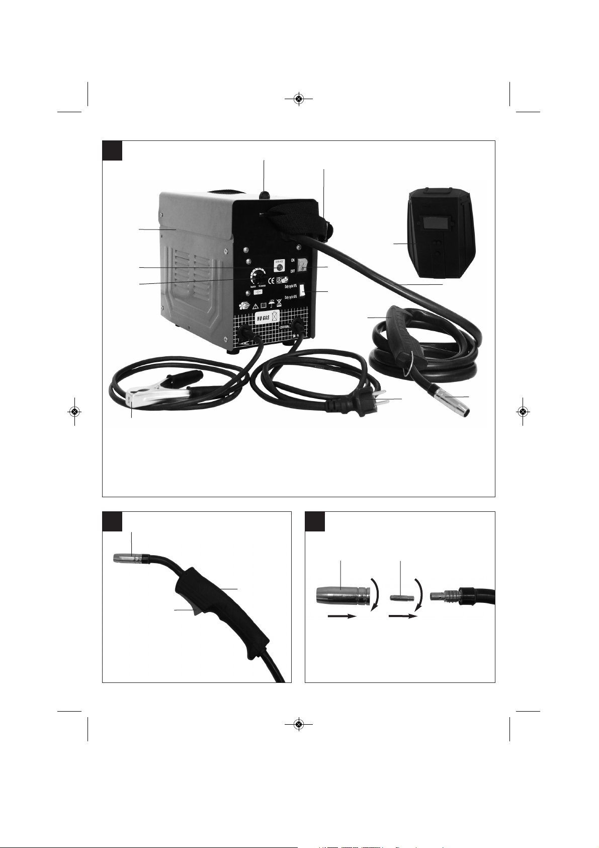
2. Layout and items supplied (Fig. 1-8)
1. Carrying strap
2. Thermostat control lamp
3. Housing cover
4. ON/OFF switch
5. Welding wire speed controller
6. Switch for welding current adjustment
7. Mains plug
8. Earth terminal
9. Hose package
10. Welding nozzle
11. Burner
12. Fastening screw for housing cover
13. Welding screen
14. Burner switch
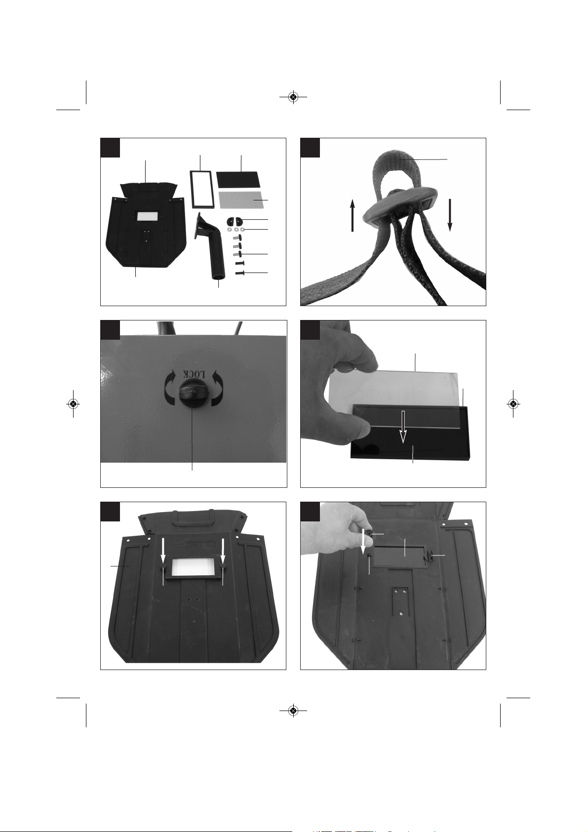
2.1 Assembly material
k. 1 x Safety glass frame
l. 1 x Welding glass
m. 1 x Transparent safety glass
n. 2 x Safety glass retaining bushes
o. 3 x Nut for handle
p. 3 x Screws for handle
q. 2 x Safety glass retaining pin
r. 1 x Handle
s. 1 x Welding screen frame
3. Intended use
The flux cored welding set is designed for selfshielding flux cored welding using suitable wire. The
additional application of gas is not required.
The equipment is to be used only for its prescribed
purpose. Any other use is deemed to be a case of
misuse. The user / operator and not the
manufacturer will be liable for any damage or injuries
of any kind caused as a result of this.
Please note that our equipment has not been
designed for use in commercial, trade or industrial
applications. Our warranty will be voided if the
equipment is used in commercial, trade or industrial
businesses or for equivalent purposes.
4. Technical data
Mains connection: 230 V ~ 50 Hz
Welding current: 45-90 A
Duty cycle X% 10 60
Welding current I2(A): 90 45
Idling voltage: 31 V
Max. welding wire drum: 0.4 kg
Welding wire diameter 0.9 mm
Fuse: 16 A
Weight: 14 kg
10
GB
Anleitung_BT_FW_100_GB_SPK7__ 13.03.13 13:12 Seite 10
Page 11

11
GB
5. Before starting the equipment
5.1 Assembly (Fig. 7-13)
5.1.1 Fitting the carrying strap (1)
n Guide the carrying strap (1) through the slit on
the rear of the equipment, over the housing
cover (3) and through the slit on the front of
equipment. Connect the ends of the carrying
strap as shown in Figure 5 and adjust the strap
to the required length.
Fitting the welding screen (13)
n Place the welding glass (l) and the transparent
safety glass (m) over it in the frame for the safety
glass (k) (Fig. 7).
n Press the safety glass retaining pins (q) into the
holes in welding screen frame (s) from the
outside. (Fig. 8).
n Place the frame for the safety glass (k) with the
welding glass (l) and transparent safety glass (m)
from the inside into the recess in the welding
frame (s), press the safety glass retaining
bushes (n) on to the safety glass retaining pins
(q) until they engage to secure the frame for the
safety glass (k). The transparent safety glass (m)
must be on the outside. (Fig. 9).
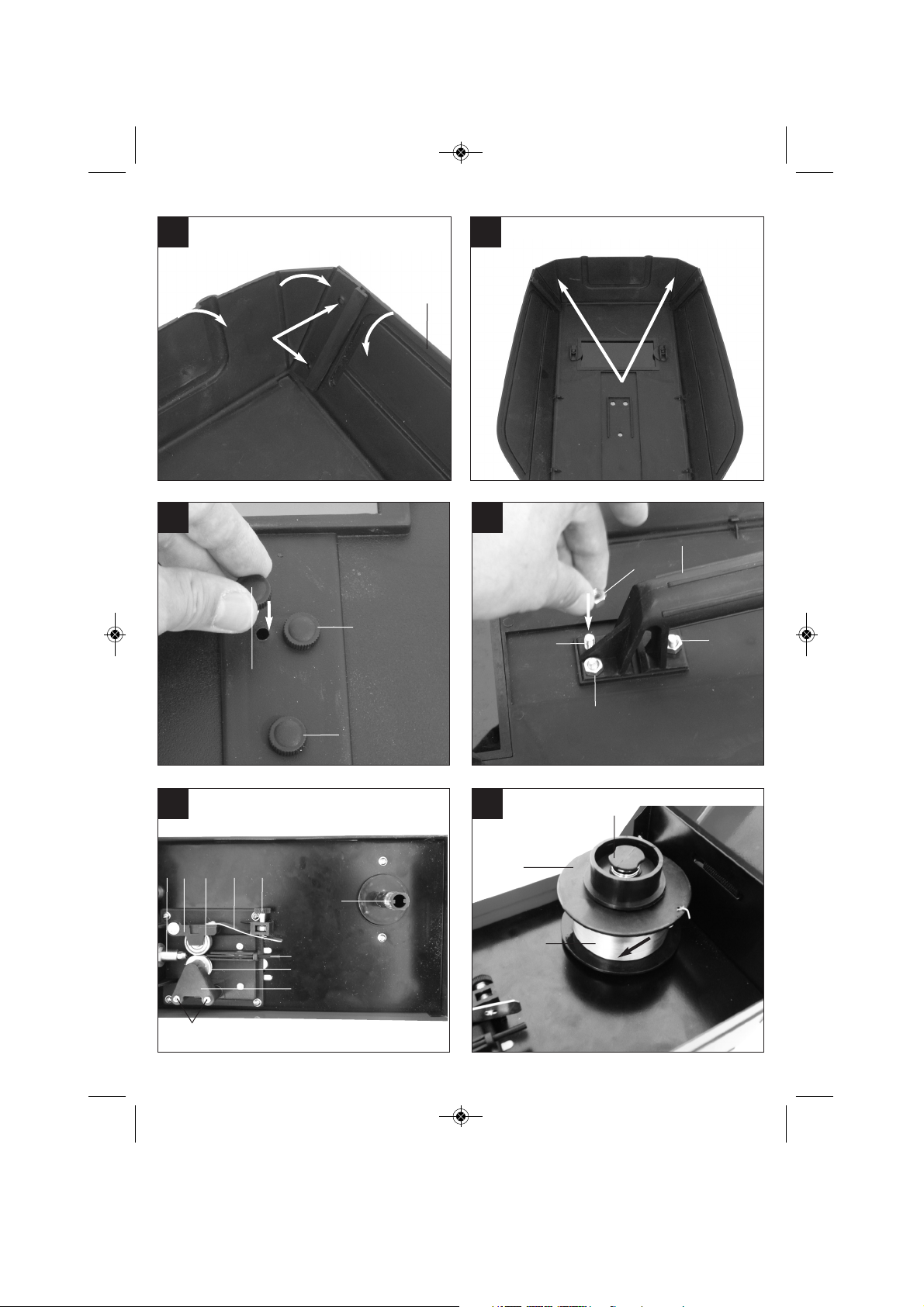
n Bend the top of the welding screen frame (s)
inwards (Fig. 10/1) and fold down the top corners
(Fig. 10/2) Now bend the outer sides of the
welding screen frame (l) inwards (Fig. 10/3) and
connect them by pressing the top corners and
outer sides together. When the retaining pins
engage, you should be able to hear 2 clear clicks
on each side (Fig. 10/4).
n When the top corners of the welding screen are
connected as shown in Figure 11, place the
screws for the handle (p) from the outside
through the three holes in the welding screen.
(Fig. 12).
n Turn over the welding screen and place the
handle (r) over the threads on the three screws
for the handle (p). Secure the handle (r) to the
welding screen using the three nuts for the
handle (o). (Fig. 13).
5.2 Mains connection
n Before you connect the equipment to the mains
supply make sure that the data on the rating
plate are identical to the mains data.
n The equipment may only be operated from
properly earthed and fused shock-proof sockets.
5.3 Fitting the wire spool (Fig. 1, 2, 3, 14 – 22)
The wire spool is not supplied.
5.3.1 Wire types
Various welding wires are required for different
applications. The welding set can be used with
welding wires with a diameter of 0.9 mm. The
appropriate feed rollers and contact tubes are
supplied with the set. The feed roller, contact tube
and wire cross-section must always match each
other.
5.3.2 Wire spool capacity
Wire spools with a maximum weight of 0.4 kg can be
fitted in the welding set.
5.3.3 Inserting the wire spool
n Unlock the housing cover (Fig. 1/3) by turning
the fastening screw (Fig. 6/12) through 90° and
flip open the cover.
n Check that the windings on the spool do not
overlap so as to ensure that the wire can be
unwound evenly.
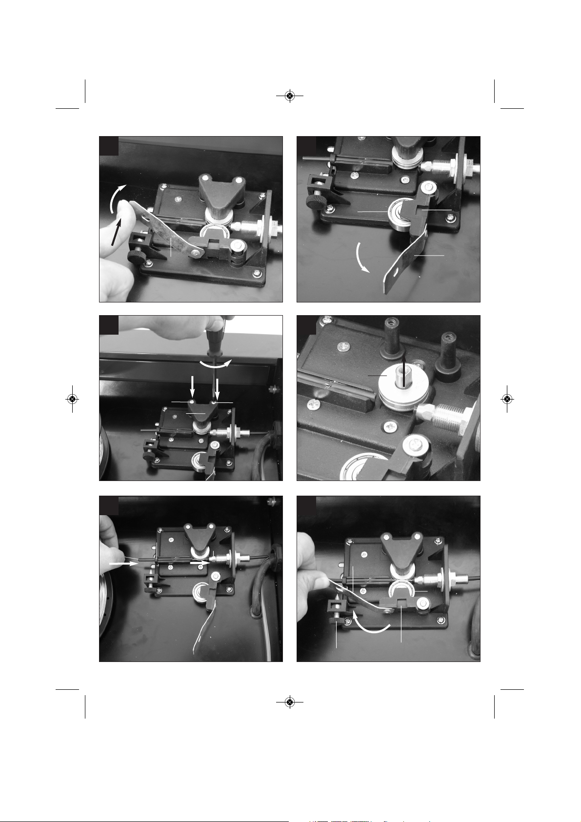
Description of the wire guide unit (Fig. 14-22)
A Wire spool
B Spool holder
C Guide tube
D Adjusting screw for roller brake
E Screws for feed roller holder
F Fee roller holder
G Feed roller
H Hose package mounting
I Pressure roller
J Pressure roller holder
K Pressure roller spring
L Adjusting screw for counter-pressure
Inserting the wire spool (Fig. 14, 15)
Place the wire spool (A) on the spool holder (B).
Ensure that the end of the welding wire is unwound
on the side of the wire guide, see arrow.
Inserting the welding wire and adjusting the wire
guide (Fig. 16-22)
n Push the pressure roller spring (K) upwards and
swing it forwards (Fig. 16).
n Pull the pressure roller holder (J) with the
pressure roller (I) and pressure roller spring (K)
downwards (Fig. 17).
n Undo the screws for the feed roller holder (E)
and pull off the feed roller holder (F) upwards
(Fig. 18).
n Check the feed roller (G). The appropriate wire
thickness must be specified on the top of the
feed roller (G). The feed roller (G) is fitted with
Anleitung_BT_FW_100_GB_SPK7__ 13.03.13 13:12 Seite 11
Page 12

12
GB
two guide grooves. Turn the feed roller (G) over
if necessary or replace it. (Fig. 19).
n Position the feed roller holder (F) again and
secure it.
n Remove the gas nozzle (Fig. 2/10) from the
burner (Fig. 2/11) by turning it clockwise,
unscrew the contact tube (Fig. 3/15). (Fig. 2 – 3).
Place the hose package (Fig. 1/9) on the floor as
straight as possible pointing away from the
welding set.
n Cut off the first 10 cm of the welding wire to
produce a straight cut with no shoulders, warping
or dirt. Deburr the end of the welding wire.
n Push the welding wire through the guide tube (C)
between the pressure and feed rollers (G/I) into
the hose package mounting (H). (Fig. 20)
Carefully push the welding wire by hand into the
hose package until it projects out of the hose
package by approx. 1 cm at the burner (Fig.
2/11).
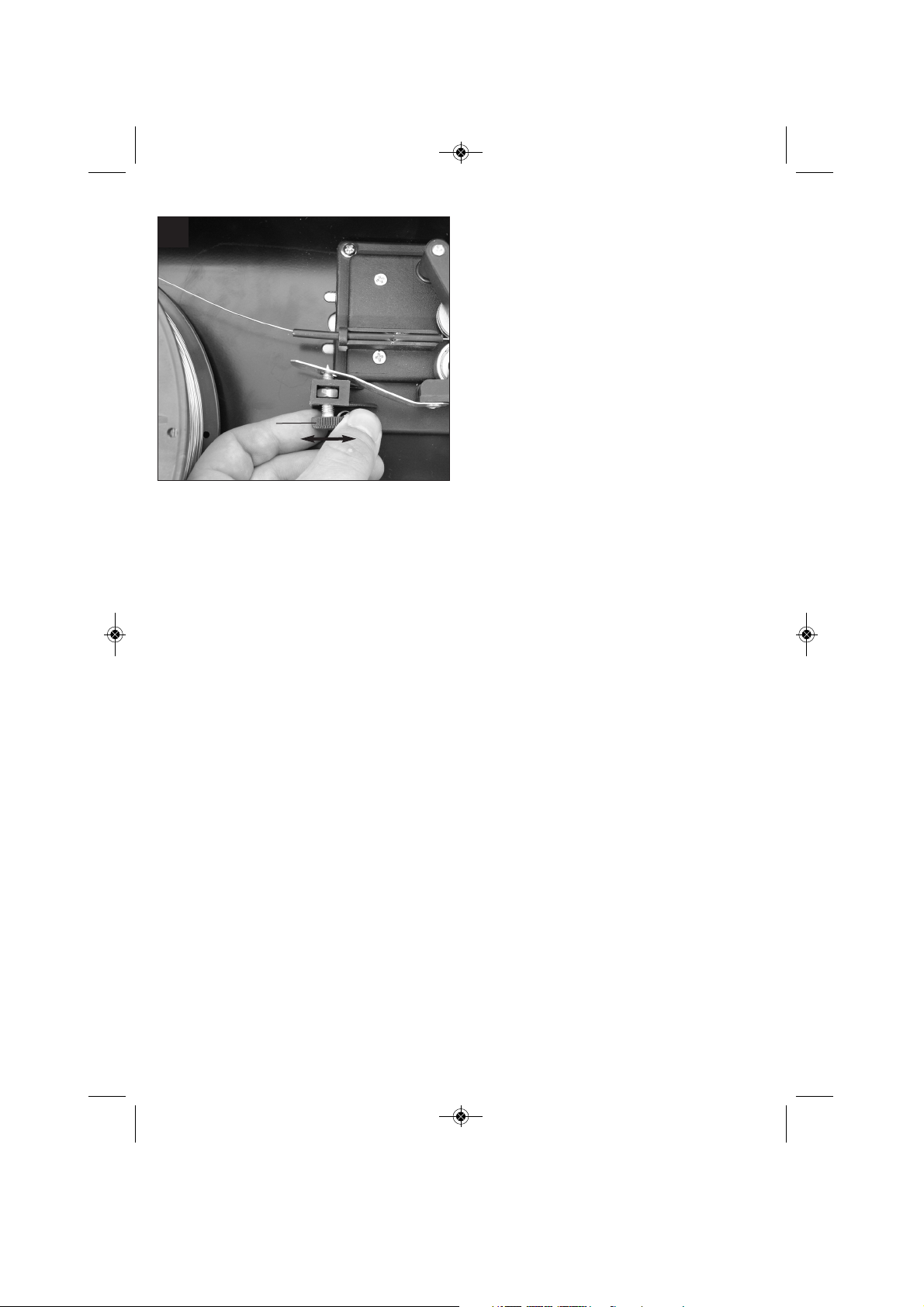
n Undo the adjusting screw for counter-pressure
(L) a few turns. (Fig. 22).
n Push the pressure roller holder (J) with pressure
roller (I) and pressure roller spring (K) upwards
again and attach the pressure roller spring (K) to
the adjusting screw for counter-pressure (L)
again (Fig. 21).
n Now set the adjusting screw for counter-pressure
(L) so that the welding wire is positioned firmly
between the pressure roller (I) and feed roller (G)
without being crushed. (Fig. 22).
n Screw the appropriate contact tube (Fig. 3/15) for
the welding wire diameter on to the burner (Fig.
2/11) and fit the gas nozzle(Fig. 2/10), turning it
clockwise.
n Set the adjusting screw for the roller brake (D) so
that the wire can still be moved and the roller
stops automatically after the wire guide has been
braked.
6. Operation
6.1 Setting
Since the welding set must be set to suit the specific
application, we recommend that the settings be
made on the basis of a test weld.
6.1.1 Setting the welding current
The welding current can be set to 2 different levels
using the welding current adjustment switch (Fig.
1/6). The required welding current depends on the
material thickness, the required penetration depth
and the welding wire diameter.
6.1.2 Setting the wire feed speed
The wire feed speed is automatically adjusted to the
current setting. The final wire feed speed setting can
be made on the welding wire speed controller (Fig.
1/5). It is advisable to start with the medium setting
and to re-adjust the speed as necessary. The
required quantity of wire depends on the material
thickness, the penetration depth, the welding wire
diameter and also the size of the gap to be bridged
between the workpieces you wish to weld.
6.2 Electrical connection
6.2.1 Mains connection
See point 5.2
6.2.2 Connecting the earth terminal (Fig. 1/8)
Connect the welding set’s earth terminal (8) in the
immediate vicinity of the welding position if possible.
Ensure that the contact point is bare metal.
6.3 Welding
When all the electrical connections for the power
supply and welding current circuit have been made,
you can proceed as follows:
The workpieces for welding must be clear of paint,
metallic coatings, dirt, rust, grease and moisture in
the area where they are to be welded.
Set the welding current and wire feed (see 6.1.1 –
6.1.3) as required.
Hold the welding screen (Fig. 4/13) in front of your
face and move the welding nozzle to the point on the
workpiece where you wish to complete the weld.
Now press the burner switch (Fig. 2/14).
Anleitung_BT_FW_100_GB_SPK7__ 13.03.13 13:12 Seite 12
Page 13

When the arc is burning, the welding set will feed
wire into the weld pool. When the weld nugget is
large enough, move the burner slowly along the
required edge. Move it to and fro if necessary to
enlarge the weld pool a little.
Find the ideal setting of the welding current and wire
feed speed by carrying out a test weld. Ideally an
even welding noise will be audible. The penetration
depth should be as deep as possible, but the weld
pool must not be allowed to fall through the
workpiece.
Do not remove the slag until the weld has cooled. If
you want to continue a welding job on an interrupted
weld seam, the slag from your initial attempt must
first be removed.
6.4 Safety equipment
6.4.1 Thermostat
The welding set is fitted with an overheating guard
that protects the welding transformer from
overheating. If the overheating guard trips, the
control lamp (2) on your set will be lit. Allow the
welding set to cool for a time.
7. Cleaning, maintenance and ordering
of spare parts
Always pull out the mains power plug before starting
any cleaning work.
7.1 Cleaning
n Keep all safety devices, air vents and the motor
housing free of dirt and dust as far as possible.
Wipe the equipment with a clean cloth or blow it
down with compressed air at low pressure.
n We recommend that you clean the equipment
immediately after you use it.
n Clean the equipment regularly with a damp cloth
and some soft soap. Do not use cleaning agents
or solvents; these may be aggressive to the
plastic parts in the equipment. Ensure that no
water can get into the interior of the equipment.
7.2 Servicing
There are no parts inside the equipment which
require additional maintenance.
7.3 Ordering replacement parts:
Please provide the following information on all orders
for spare parts:
n Model/type of the equipment
n Article number of the equipment
n ID number of the equipment
n Spare part number of the required spare part
For our latest prices and information please go to
www.isc-gmbh.info
8. Disposal and recycling
The equipment is supplied in packaging to prevent it
from being damaged in transit. The raw materials in
this packaging can be reused or recycled. The
equipment and its accessories are made of various
types of material, such as metal and plastic.
Defective components must be disposed of as
special waste. Ask your dealer or your local council.
13
GB
Anleitung_BT_FW_100_GB_SPK7__ 13.03.13 13:12 Seite 13
Page 14
14
GB
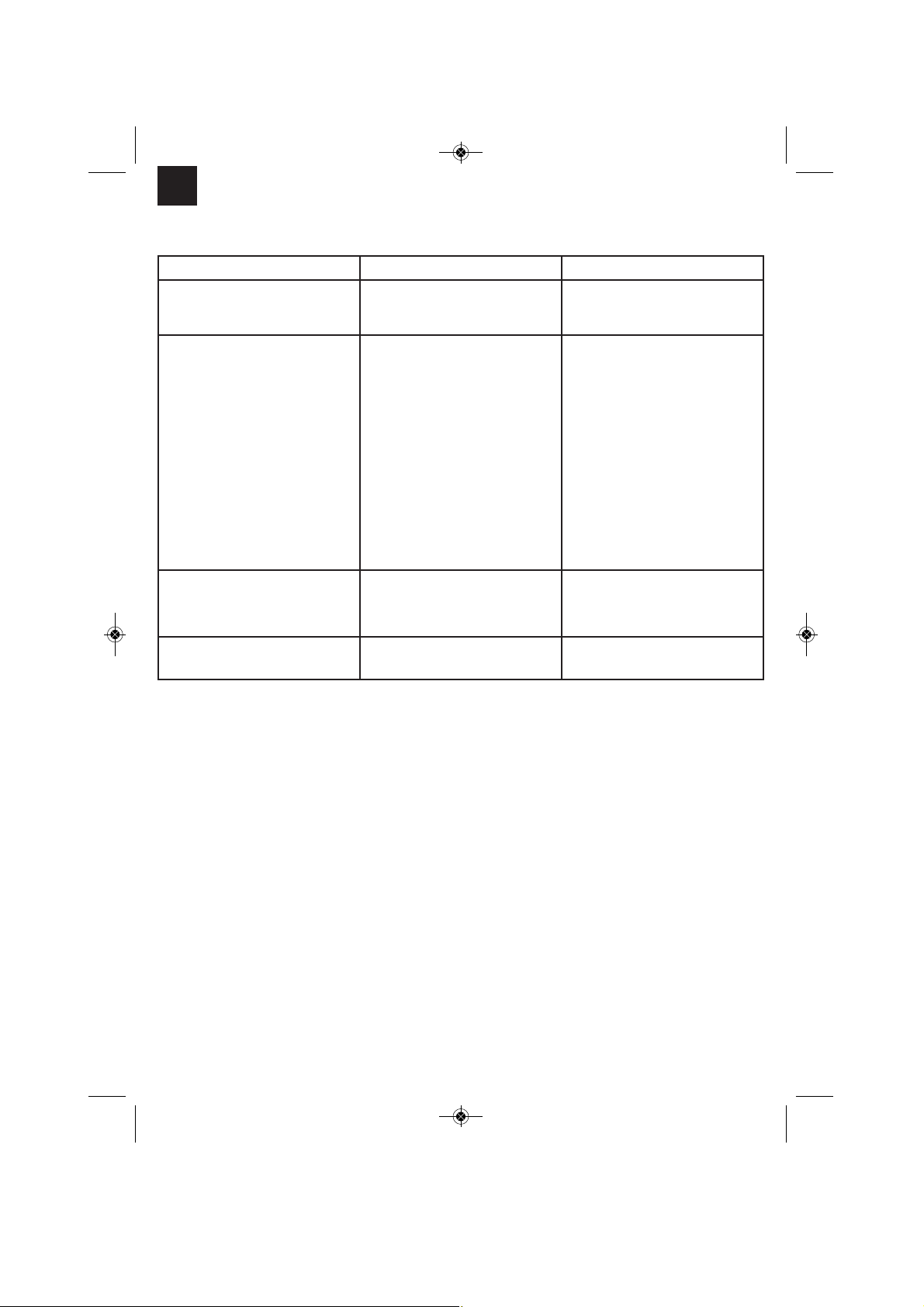
Fault Cause Remedy
Feed roller does not turn Power supply not connected
Wire feed controller set to 0
Check connection
Check setting
Feed roller turns, but does not feed
any wire
Incorrect roller pressure (see 5.3.3)
Roller brake set too firmly (see
5.3.3)
Dirty / damaged feed roller (see
5.3.3)
Damaged hose package
Contact tube wrong size / dirty /
worn (see 5.3.3)
Welding wire welded to the gas
nozzle / contact tube
Check setting
Check setting
Clean or replace
Check the wire guide jacket
Clean or replace
Release
After a lengthy period of use the
welding set does not work any
longer, the thermostat (2) control
light is lit
The welding set has overheated
due to being used for too long and
a failure to observe the reset time
Leave the set to cool down for at
least 20 – 30 minutes
Very poor weld Incorrect current / feed setting (see
6.1.1/6.1.2)
Check setting
9. Troubleshooting
Anleitung_BT_FW_100_GB_SPK7__ 13.03.13 13:12 Seite 14
Page 15

15
GB
10. Key to symbols
EN 60974-1 European standard for
arc welding sets and
welding power supplies
with limited on time
Do not store or use the
equipment in wet or
damp conditions or in
the rain.
U
s
Standardized operating
voltage
Single-phase mains
connection
U
1
Mains voltage ~ 50 Hz Mains frequency
I1max Rated maximum mains
current
Symbol for falling
characteristic curve
Read the operating
instructions carefully
before using the welding
set and follow them
Self-shielding flux cored
welding
U
0
Rated idling voltage IP 21 S Protection type
I
2
Welding current X On-load factor
Ø mm Welding wire diameter I1eff Effective value of the
highest line current
Single-phase
transformer
1쓒
1쓒
1 ~
Anleitung_BT_FW_100_GB_SPK7__ 13.03.13 13:12 Seite 15
Page 16

t For EU countries only
Never place any electric tools in your household refuse.
To comply with European Directive 2002/96/EC concerning old electric and electronic equipment and its
implementation in national laws, old electric tools have to be separated from other waste and disposed of
in an environment-friendly fashion, e.g. by taking to a recycling depot.
Recycling alternative to the demand to return electrical devices:
As an alternative to returning the electrical device, the owner is obliged to cooperate in ensuring that the
device is properly recycled if ownership is relinquished. This can also be done by handing over the used
device to a returns center, which will dispose of it in accordance with national commercial and industrial
waste management legislation. This does not apply to the accessories and auxiliary equipment without
any electrical components which are included with the used device.
16
t
Given unfavorable conditions in the power supply the equipment may cause the voltage to drop temporarily. If the supply
impedance “Z” at the connection point to the public power supply exceeds 0,448 Ω it may be necessary to take further measures
before the equipment can be used as intended from this power supply. If necessary, you can ask your local electricity supply
company for the impedance value.
Anleitung_BT_FW_100_GB_SPK7__ 13.03.13 13:12 Seite 16
Page 17

17
The reprinting or reproduction by any other means, in whole or in part,
of documentation and papers accompanying products is permitted only
with the express consent of ISC GmbH.
Technical changes subject to change
Anleitung_BT_FW_100_GB_SPK7__ 13.03.13 13:12 Seite 17
Page 18

18
Anleitung_BT_FW_100_GB_SPK7__ 13.03.13 13:12 Seite 18
Page 19

19
t
GUARANTEE CERTIFICATE
Dear Customer,
All of our products undergo strict quality checks to ensure that they reach you in perfect condition. In the unlikely
event that your device develops a fault, please contact our service department at the address shown on this
guarantee card. Of course, if you would prefer to call us then we are also happy to offer our assistance under the
service number printed below. Please note the following terms under which guarantee claims can be made:
1. These guarantee terms cover additional guarantee rights and do not affect your statutory warranty rights.
We do not charge you for this guarantee.
2. Our guarantee only covers problems caused by material or manufacturing defects, and it is restricted to the
rectification of these defects or replacement of the device. Please note that our devices have not been
designed for use in commercial, trade or industrial applications. Consequently, the guarantee is invalidated
if the equipment is used in commercial, trade or industrial applications or for other equivalent activities. The
following are also excluded from our guarantee: compensation for transport damage, damage caused by
failure to comply with the installation/assembly instructions or damage caused by unprofessional
installation, failure to comply with the operating instructions (e.g. connection to the wrong mains voltage or
current type), misuse or inappropriate use (such as overloading of the device or use of non-approved tools
or accessories), failure to comply with the maintenance and safety regulations, ingress of foreign bodies into
the device (e.g. sand, stones or dust), effects of force or external influences (e.g. damage caused by the
device being dropped) and normal wear resulting from proper operation of the device.
This applies in
particular to rechargeable batteries for which we nevertheless issue a guarantee period of 12 months.
The guarantee is rendered null and void if any attempt is made to tamper with the device.
3. The guarantee is valid for a period of 2 years starting from the purchase date of the device. Guarantee
claims should be submitted before the end of the guarantee period within two weeks of the defect being
noticed. No guarantee claims will be accepted after the end of the guarantee period. The original guarantee
period remains applicable to the device even if repairs are carried out or parts are replaced. In such cases,
the work performed or parts fitted will not result in an extension of the guarantee period, and no new
guarantee will become active for the work performed or parts fitted. This also applies when an on-site
service is used.
4. In order to assert your guarantee claim, please send your defective device postage-free to the address
shown below. Please enclose either the original or a copy of your sales receipt or another dated proof of
purchase. Please keep your sales receipt in a safe place, as it is your proof of purchase. It would help us if
you could describe the nature of the problem in as much detail as possible. If the defect is covered by our
guarantee then your device will either be repaired immediately and returned to you, or we will send you a
new device.
Of course, we are also happy offer a chargeable repair service for any defects which are not covered by the
scope of this guarantee or for units which are no longer covered. To take advantage of this service, please send
the device to our service address.
Anleitung_BT_FW_100_GB_SPK7__ 13.03.13 13:12 Seite 19
Page 20

EH 03/2013 (01)
Anleitung_BT_FW_100_GB_SPK7__ 13.03.13 13:12 Seite 20
 Loading...