


 Loading...
Edwards nXDS15iR, nXDS20i, nXDS15iC, nXDS15i, nXDS6i Instruction Manual
...A735-01-880
Issue F
Instruction Manual
nXDS Scroll Pump
Description |
Item Number |
|
|
nXDS6i |
A735-01-983 |
nXDS10i |
A736-01-983 |
nXDS15i |
A737-01-983 |
nXDS20i |
A738-01-983 |
nXDS6iC |
A735-02-983 |
nXDS10iC |
A736-02-983 |
nXDS15iC |
A737-02-983 |
nXDS20iC |
A738-02-983 |
nXDS6iR |
A735-03-983 |
nXDS10iR |
A736-03-983 |
nXDS15iR |
A737-03-983 |
nXDS20iR |
A738-03-983 |
|
|
Original Instructions

Declaration of Conformity
Edwards Ltd,
Innovation Drive,
Burgess Hill,
West Sussex, RH15 9TW, UK
The following products: |
|
|
nXDS6i scroll pump |
100-127/200-240V, 50/60Hz |
A735-01-983 |
nXDS10i scroll pump |
100-127/200-240V, 50/60Hz |
A736-01-983 |
nXDS15i scroll pump |
100-127/200-240V, 50/60Hz |
A737-01-983 |
nXDS20i scroll pump |
100-127/200-240V, 50/60Hz |
A738-01-983 |
nXDS6iC scroll pump |
100-127/200-240V, 50/60Hz |
A735-02-983 |
nXDS10iC scroll pump |
100-127/200-240V, 50/60Hz |
A736-02-983 |
nXDS15iC scroll pump |
100-127/200-240V, 50/60Hz |
A737-02-983 |
nXDS20iC scroll pump |
100-127/200-240V, 50/60Hz |
A738-02-983 |
nXDS6iR scroll pump |
100-127/200-240V, 50/60Hz |
A735-03-983 |
nXDS10iR scroll pump |
100-127/200-240V, 50/60Hz |
A736-03-983 |
nXDS15iR scroll pump |
100-127/200-240V, 50/60Hz |
A737-03-983 |
nXDS20iR scroll pump |
100-127/200-240V, 50/60Hz |
A738-03-983 |
Is in conformity with the relevant requirements of European CE legislation:
2006/42/EC |
Machinery directive |
2014/35/EU |
Low voltage directive |
2014/30/EU |
Electromagnetic compatibility (EMC) directive |
2014/34/EU |
ATEX directive on use in potentially explosive atmospheres |
|
II 3 G Ex h IIB T4 Gc Internal Atmospheres Only, Tech File ref 209 |
2011/65/EU |
Restriction of certain hazardous substances (RoHS) directive |
Based on the relevant requirements of harmonised standards:
EN 1012-2:1996 |
Compressors and vacuum pumps. Safety requirements. Vacuum pumps |
+A1:2009 |
|
BS EN ISO 80079- |
Non-electrical equipment for explosive atmospheres. Basic method and requirement |
36:2016 |
|
BS EN ISO 80079- |
Non-electrical equipment for explosive atmospheres. Non-electrical type of |
37:2016 |
constructional safety ‘c’ |
EN 61010-1:2010 |
Safety requirements for electrical equipment for measurement, control and |
|
laboratory use. General requirements |
EN 61326-1:2013 |
Electrical equipment for measurement, control and laboratory use. EMC |
|
requirements. General requirements |
|
Class A Emissions, Industrial Immunity |
The product also complies with the following:
CSA-C22.2 |
Safety requirements for electrical equipment for measurement, control and |
No.61010-1-12 |
laboratory use – Part 1: General requirements |
UL61010-1 |
Safety requirements for electrical equipment for measurement, control and |
3rd Edition |
laboratory use – Part 1: General requirements |
This covers all product serial numbers from the date of this declaration onwards.
|
|
19.10.2018, Burgess Hill |
|
|
|
Mr Ian Keech |
|
Date and Place |
Vice President Engineering, High Vacuum Division |
|
|
This product has been manufactured under a quality management system certified to ISO 9001:2015.
This declaration is based on the requirements of EN ISO 17050-1 and the relevant directives.
<![endif]>P200-06-720-F

P200-10-019
Issue D
Material Declaration
In accordance with the requirements of the Chinese regulatory requirement on the Management Methods for the Restriction of the Use of Hazardous Substances in Electrical and Electronic Products Order No. 32 (also known as ‘China RoHS2’) and SJ/T 11364 Marking for the Restricted Use of Hazardous Substances in Electronic and Electrical Products:
|
|
|
|
|
|
|
|
|
|
Product Labels |
|
|
||
Product |
Product Label |
|
|
|
|
|
Meaning |
|
||||||
|
|
|
|
|
|
|
|
|
This product contains hazardous substances in at least one of the |
|||||
All pumps in the |
|
|
|
|
|
|
|
|
homogeneous materials used which are above the limit requirement |
|||||
|
|
20 |
|
|
||||||||||
list below |
|
|
|
|
in GB/T 26572 as detailed in the declaration table below. |
|||||||||
|
|
|
|
|
|
|
|
|||||||
|
|
|
|
|
|
|
|
|
These parts can safely be used for the environmental protection use |
|||||
|
|
|
|
|
|
|
|
|
||||||
|
|
|
|
|
|
|
|
|
period as indicated. |
|
|
|||
|
|
|
|
|
|
|
|
|
|
|
|
|||
Pump Type |
|
|
|
|
|
Pump Size |
|
|
|
|||||
RV Pumps |
|
|
|
|
|
RV3,5,8,12, E Lab, nRVi |
|
|
|
|||||
EM Small Pumps |
|
|
|
|
|
E2M0.7, 1.5, E1M18, E2M18, 28, 30, nE2M40i |
|
|
||||||
nEXT Pumps |
|
|
|
|
|
nEXT 85, 240, 300, 400, Splitflow |
|
|
||||||
nXDS pumps |
|
|
|
|
|
nXDS 6, 10, 15, 20 |
|
|
|
|||||
EXT pumps |
|
|
|
|
|
EXT75DX |
|
|
|
|
|
|
||
XDS pumps |
|
|
|
|
|
XDS35, 46, 100 |
|
|
|
|||||
Diaphragm |
|
|
|
|
|
XDD 1, D lab |
|
|
|
|||||
Turbo Pump Carts |
|
|
|
|
|
T station, nEXPT, nEXT station |
|
|
|
|||||
|
|
|
|
|
|
|
|
|
|
|
|
|
||
|
|
|
|
|
|
|
|
|
Materials Content Declaration |
|
||||
|
|
|
|
|
|
|
|
|
|
|
|
|
|
|
|
|
|
|
|
|
|
|
|
|
|
|
|
|
|
|
|
|
|
|
|
|
|
|
|
|
|
|
|
|
|
|
|
|
|
|
|
|
|
|
|
|
|
||
|
|
|
|
|
|
Hexavalent |
Polybrominated |
|||||||
Part name |
|
Lead |
|
|
|
Mercury |
|
Cadmium |
|
Polybrominated |
||||
|
|
|
|
|
|
Chromium |
diphenyl ethers |
|||||||
|
|
(Pb) |
|
|
|
(Hg) |
|
(Cd) |
|
biphenyls (PBB) |
||||
|
|
|
|
|
|
|
(Cr VI) |
(PBDE) |
||||||
|
|
|
|
|
|
|
|
|
|
|
|
|
||
|
|
X |
|
|
|
O |
|
O |
|
O |
O |
O |
||
Cast Aluminium |
|
|
|
|
|
|
||||||||
|
|
|
|
|
|
|
|
|
|
|
|
|
|
|
|
|
X |
|
|
|
O |
|
O |
|
O |
O |
O |
||
Brass pipe Fittings |
|
|
|
|
|
|
||||||||
|
|
|
|
|
|
|
|
|
|
|
|
|
|
|
|
|
X |
|
|
|
O |
|
O |
|
O |
O |
O |
||
Brass Connectors |
|
|
|
|
|
|
||||||||
|
|
|
|
|
|
|
|
|
|
|
|
|
|
|
O GB/T 26572 |
|
|||||||||||||
O: Indicates that the hazardous substance contained in all of the homogeneous materials for this part is below the limit requirement in GB/T 26572.
X GB/T26572
X: Indicates that the hazardous substance contained in at least one of the homogeneous materials used for this part is above the limit requirement of GB/T26572.
NOTES: These products are EU RoHS compliant, the following Exemptions apply: 6(b) Lead as an alloying element in aluminium containing up to 0.4% by weight. 6(c) Copper alloy containing up to 4% lead by weight
Packaging Information
Pallet |
Over-shipper |
Protection Pieces |
Support Braces |
|
|
|
|
NW |
|
|
|
|
|
|
|
Recyclable Natural Wood |
Recyclable Cardboard |
Recyclable Polypropylene |
Recyclable Mild Steel |
|
|
|
|
This page has been intentionally left blank.

|
|
|
A735-01-880 Issue F |
|
|
|
|
||
|
Contents |
|
||
|
Section |
Page |
||
|
1 |
Introduction ........................................................................................ |
1 |
|
|
1.1 |
Scope of this manual .................................................................................................... |
1 |
|
|
1.2 |
ATEX directive implication ............................................................................................. |
2 |
|
|
1.3 |
General description ..................................................................................................... |
2 |
|
|
1.4 |
Pump controller.......................................................................................................... |
3 |
|
|
1.5 |
Logic interface ........................................................................................................... |
4 |
|
|
1.6 |
Gas ballast control ...................................................................................................... |
4 |
|
|
2 |
Technical data ..................................................................................... |
7 |
|
|
2.1 |
Operating and storage conditions ..................................................................................... |
7 |
|
|
2.2 |
Performance.............................................................................................................. |
7 |
|
|
2.2.1 |
General................................................................................................................... |
. 7 |
|
|
2.2.2 |
Pumping media........................................................................................................... |
8 |
|
|
2.2.3 |
Performance characteristics ........................................................................................... |
8 |
|
|
2.3 |
Mechanical data ........................................................................................................ |
11 |
|
|
2.3.1 |
General................................................................................................................... |
11 |
|
|
2.3.2 |
Sound and vibration data.............................................................................................. |
11 |
|
|
2.3.3 |
Construction............................................................................................................. |
11 |
|
|
2.4 |
Electrical data .......................................................................................................... |
11 |
|
|
2.4.1 |
Electrical cables ........................................................................................................ |
12 |
|
|
2.5 |
Logic interface data.................................................................................................... |
12 |
|
|
2.6 |
LED indicators ........................................................................................................... |
14 |
|
|
3 |
Installation ....................................................................................... |
15 |
|
|
3.1 |
Safety..................................................................................................................... |
15 |
|
|
3.2 |
System design considerations......................................................................................... |
15 |
|
|
3.3 |
Unpack and inspect .................................................................................................... |
17 |
|
|
3.4 |
Position the pump ...................................................................................................... |
17 |
|
|
3.4.1 |
Mechanical fixing ....................................................................................................... |
17 |
|
|
3.5 |
Connect to the vacuum system....................................................................................... |
17 |
|
|
3.6 |
Electrical installation .................................................................................................. |
18 |
|
|
3.6.1 |
Fuses and circuit breakers ............................................................................................ |
18 |
|
|
3.6.2 |
Electrical supply connection .......................................................................................... |
19 |
|
|
3.6.3 |
Disconnect the pump from the electrical supply .................................................................. |
19 |
|
|
3.7 |
Connection for remote control and monitoring.................................................................... |
19 |
|
|
3.7.1 |
Connect the logic interface to the control equipment ........................................................... |
19 |
|
|
4 |
Operation ......................................................................................... |
21 |
|
|
4.1 |
Operational modes ..................................................................................................... |
21 |
|
|
4.2 |
Manual operation ....................................................................................................... |
21 |
|
|
4.2.1 |
Start and stop ........................................................................................................... |
22 |
|
|
4.2.2 |
Standby................................................................................................................... |
22 |
|
|
4.3 |
Parallel control and monitoring ...................................................................................... |
23 |
|
|
4.4 |
Analogue speed control................................................................................................ |
24 |
|
|
4.4.1 |
Hardware configuration ............................................................................................... |
25 |
|
|
4.4.2 |
Operation ................................................................................................................ |
25 |
|
|
4.5 |
Auto-run.................................................................................................................. |
26 |
|
| <![if ! IE]> <![endif]>gp/0281/01/18 |
4.6 |
Use of gas ballast control ............................................................................................. |
26 |
|
4.6.1 |
Gas ballast control |
26 |
||
|
||||
|
4.7 |
Start up procedure ..................................................................................................... |
26 |
|
|
4.8 |
To achieve ultimate vacuum.......................................................................................... |
27 |
|
|
4.9 |
To pump condensable vapours ....................................................................................... |
27 |
|
|
|
|
||
|
© Edwards Limited 2018. All rights reserved. |
Page i |
||
<![endif]>Contents

A735-01-880 Issue F
<![endif]>Contents
4.10
5
5.1
5.2
5.3
5.4
5.5
5.6
5.7
5.8
5.9
5.10
5.11
5.11.1
5.11.2
5.11.3
5.11.4
5.11.5
5.11.6
Shut down................................................................................................................ |
27 |
Maintenance...................................................................................... |
29 |
Safety information...................................................................................................... |
29 |
Maintenance plan....................................................................................................... |
30 |
Inspect and clean the inlet strainer ................................................................................. |
30 |
Clean the external fan cover ......................................................................................... |
30 |
Check the pump performance (service indicator) ................................................................. |
30 |
Replace the tip-seals................................................................................................... |
31 |
Replace the pump bearings (service indicator) .................................................................... |
31 |
Replace the pump controller (service indicator) .................................................................. |
31 |
Electrical safety check................................................................................................. |
31 |
Service indicator codes ................................................................................................ |
32 |
Fault finding............................................................................................................. |
32 |
The pump has failed to start or has stopped....................................................................... |
32 |
The pump has failed to achieve the required performance ..................................................... |
32 |
The pump has poor ultimate vacuum................................................................................ |
33 |
The pump is noisy ...................................................................................................... |
33 |
The pump surface temperature is high ............................................................................. |
33 |
Alarm indicator codes.................................................................................................. |
34 |
6 |
Storage and disposal ............................................................................ |
37 |
6.1 |
Storage ................................................................................................................... |
37 |
6.2 |
Disposal .................................................................................................................. |
37 |
7 |
Spares and accessories ......................................................................... |
39 |
7.1 |
Introduction ............................................................................................................. |
39 |
7.2 |
Accessories .............................................................................................................. |
40 |
7.2.1 |
Silencer................................................................................................................... |
41 |
7.2.2 |
Gas ballast adaptor..................................................................................................... |
41 |
7.2.3 |
Gas ballast adaptor blank ............................................................................................. |
41 |
7.2.4 |
Vibration isolators ...................................................................................................... |
41 |
7.2.5 |
Inlet/exhaust filter..................................................................................................... |
41 |
7.2.6 |
Exhaust nozzle .......................................................................................................... |
42 |
7.2.7 |
Chemical resistance conversion kit .................................................................................. |
42 |
7.2.8 |
Electrical cables ........................................................................................................ |
42 |
7.2.9 |
Pump-to-controller cable ............................................................................................. |
42 |
7.3 |
Spares .................................................................................................................... |
43 |
7.3.1 |
Tip-seal kit (Youtube video https://www.youtube.com/watch?v=vKnh9dxOyhE) ........................... |
43 |
7.3.2 |
Cooling fan............................................................................................................... |
43 |
7.3.3 |
Gas ballast knob ........................................................................................................ |
43 |
7.3.4 |
Silencer spares kit ...................................................................................................... |
43 |
7.3.5 |
Inlet/exhaust filter spares ............................................................................................ |
43 |
7.3.6 |
Bearing replacement kit (not field serviceable) ................................................................... |
44 |
7.3.7 |
Exhaust and ballast valve kit ......................................................................................... |
44 |
|
For return of equipment, complete the HS Forms at the end of this manual. |
|
Page ii |
© Edwards Limited 2018. All rights reserved. |

|
|
A735-01-880 Issue F |
Illustrations |
|
|
Figure |
|
Page |
1 |
nXDS scroll pump ......................................................................................................... |
3 |
2 |
Quick start guide (manual control mode)............................................................................. |
5 |
3 |
nXDS6i Performance characteristics ................................................................................... |
9 |
4 |
nXDS10i Performance characteristics ................................................................................. |
9 |
5 |
nXDS15i Performance characteristics ................................................................................ |
10 |
6 |
nXDS20i Performance characteristics ................................................................................ |
10 |
7 |
LED indicators ............................................................................................................ |
14 |
8 |
Installation drawing ..................................................................................................... |
16 |
9 |
User interface panel .................................................................................................... |
22 |
10 |
Logic interface connections - parallel control ...................................................................... |
23 |
11 |
Logic interface connections - analogue speed control............................................................. |
24 |
12 |
Analogue speed control................................................................................................. |
25 |
13 |
Poor ultimate vacuum flow chart ..................................................................................... |
33 |
14 |
Noisy pump flow chart .................................................................................................. |
34 |
15 |
nXDS accessories......................................................................................................... |
40 |
Tables |
|
|
Table |
|
Page |
1 |
nXDS Control modes ...................................................................................................... |
6 |
2 |
Operating and storage conditions ...................................................................................... |
7 |
3 |
Environmental conditions ............................................................................................... |
7 |
4 |
General characteristics .................................................................................................. |
7 |
5 |
Performance characteristics ............................................................................................ |
8 |
6 |
General mechanical data............................................................................................... |
11 |
7 |
Sound and vibration data............................................................................................... |
11 |
8 |
Electrical ratings for continuous operation.......................................................................... |
11 |
9 |
Recommended regional supply protection........................................................................... |
11 |
10 |
Recommended cord sets................................................................................................ |
12 |
11 |
Logic interface technical data......................................................................................... |
12 |
12 |
Logic interface connector pins ........................................................................................ |
13 |
13 |
LED indicators ............................................................................................................ |
14 |
14 |
Maintenance plan........................................................................................................ |
30 |
15 |
Flashing service codes .................................................................................................. |
32 |
16 |
Flashing error codes..................................................................................................... |
35 |
17 |
Silencer.................................................................................................................... |
41 |
18 |
Gas ballast adaptor...................................................................................................... |
41 |
19 |
Gas ballast blank adaptor .............................................................................................. |
41 |
20 |
Vibration isolators ....................................................................................................... |
41 |
21 |
Inlet/exhaust filter...................................................................................................... |
41 |
22 |
Exhaust nozzle ........................................................................................................... |
42 |
23 |
Chemical resistance conversion kit ................................................................................... |
42 |
24 |
Electrical cables ......................................................................................................... |
42 |
25 |
Pump-to-controller cables ............................................................................................. |
42 |
26 |
Tip-seal kit................................................................................................................ |
43 |
27 |
Cooling fan................................................................................................................ |
43 |
28 |
Gas ballast knob ......................................................................................................... |
43 |
<![endif]>Contents
© Edwards Limited 2018. All rights reserved. |
Page iii |

A735-01-880 Issue F
<![endif]>Contents
29 |
Silencer spares kit ....................................................................................................... |
43 |
30 |
Inlet/exhaust filter spares ............................................................................................. |
43 |
31 |
Bearing replacement kit................................................................................................ |
44 |
32 |
Exhaust and ballast valve kit .......................................................................................... |
44 |
Associated publications
Publication title |
Publication number |
Vacuum Pump and Vacuum System Safety |
P400-40-100 |
nXDS Serial Comms Interface Instruction Manual |
A735-01-860 |
Trademark credits
Edwards and the Edwards logo are trademarks of Edwards Limited, Innovation Drive, Burgess Hill, West Sussex, RH15 9TW, UK.
Page iv |
© Edwards Limited 2018. All rights reserved. |
A735-01-880 Issue F
1 Introduction
1.1Scope of this manual
This manual provides installation, operation and maintenance instructions for the Edwards nXDS series of scroll pump. The pump must be used as specified in this manual or the protection provided by the equipment may be impaired. Read this manual before installing and operating the pump.
Important safety information is highlighted as WARNING and CAUTION instructions; these instructions must be obeyed. The use of WARNINGS and CAUTIONS is defined below.
WARNING
Warnings are given where failure to observe the instruction could result in injury or death to people. The actual symbol shown varies according to the hazard.
CAUTION
Cautions are given where failure to observe the instruction could result in damage to the equipment, associated equipment and process.
Pressures are stated as absolute pressures unless otherwise stated.
The units used throughout this manual conform to the SI international system of units of measurement. The following warning labels may be present on the pump and used throughout the product documentation.
Warning – an appropriate safety instruction should be followed or a caution to a potential hazard exists.
Warning – dangerous voltage. Indicates hazards arising from dangerous voltages.
Warning – hot surfaces. To indicate that the marked item can be hot and should not be touched without taking precautions.
Warning – risk of explosion. Indicates the potential risk of explosion.
Warning – heavy object. Indicates the potential risk of physical injury and requires suitable lifting equipment to move.
<![endif]>Introduction
© Edwards Limited 2018. All rights reserved. |
Page 1 |

A735-01-880 Issue F
<![endif]>Introduction
1.2
ATEX directive implication
This equipment is designed to meet the requirements of Group II Category 3G in respects to ignition sources internal to the pump. This classification is in accordance with Directive 2014/34/EU.
The pumping mechanism and its mechanical components exposed to the “INTERNAL ATMOSPHERES” within the nXDS pump system is defined as: equipment group II; equipment category 3 – in accordance with the ATEX directive. This designation ONLY applies to the mechanical pumping mechanism, which is hermetically sealed from the external pump system and its operating environment. An ATEX category has not been assigned in respect of potential ignition sources on the outside of the equipment as the equipment has not been designed for use where there is an external potentially explosive atmosphere.
There is no potential source of ignition within the pump during normal operation but there may be potential sources of ignition under conditions of rare or unexpected malfunction as defined in the Directive. As a result of this, it is necessary to consider the potential consequences of ignition sources occurring under rare or expected malfunction. (Ref ATEX137 1992/92/EC).
When flammable materials are present within the equipment you must:
Not allow air to enter the equipment.
Ensure the system is leak tight.
Use an inert gas purge (for example, nitrogen) to dilute any flammable gasses or vapours entering the pump inlet, and/or use an inert gas purge to reduce the concentration of flammable gases or vapours in the pump and in the exhaust pipeline, to less than one quarter of the gases published Lower Explosion Limits (LEL).
Do not pump pyrophoric materials, process debris could produce an ignition source on the scroll surface.
Do not locate the pump in an ATEX zoned area, the ATEX specification is not applicable for external atmospheres.
When planning to pump hazardous substances with this pump, read the related chapters in the Safety Booklet and in these Operating Instructions first.
Further details can be obtained by contacting Edwards.
1.3General description
The nXDS pump is shown in Figure 1.
The nXDS pump is a truly dry vacuum pump as all the bearings, with their hydrocarbon lubricant, are isolated from the vacuum space. The nXDS pump is suitable for use on vapour handling processes, and may be used for some pumping applications involving corrosive substances. For information on pumping flammable gases, contact Edwards.
The body of the pump includes a fixed scroll and an orbiting scroll. The orbiting scroll is controlled by an electric motor through an eccentric cam on the motor drive shaft. The movement of the orbiting scroll, meshed with the fixed scroll, forms successive crescent shaped volumes in the pump. Gas that enters the pump through the inlet is compressed by the movement of the orbiting scroll and swept towards the centre of the fixed scroll. The compressed gas enters the exhaust port near the centre of the fixed scroll and is exhausted from the pump through the outlet.
Refer to Section 2.1 for details of operating conditions.
Page 2 |
© Edwards Limited 2018. All rights reserved. |

A735-01-880 Issue F
1.4Pump controller
The integral pump controller manages the supply of current to a three-phase electric motor in accordance with operating conditions. The controller monitors power and temperature, and will protect the pump in the event of operation under sustained high load or under fault conditions.
The controller provides the user interface (refer to Figure 1). The pump may be operated in these modes:
Manually, using the buttons on the interface panel. Refer to Figures 2 and 9.
Remotely via serial communications or digital and analogue process control (parallel), via the 15-way D-type logic interface connector. Refer to Section 1.5.
Figure 1 - nXDS scroll pump
<![endif]>Introduction
1. |
Lifting eye |
7. |
15-way D-type connector |
2. |
NW25 inlet port |
8. |
USB port (service mode only) |
3. |
Gas ballast control |
9. |
User interface panel |
4. |
Cooling fan |
10. Mains power connector |
|
5. |
NW25 exhaust port |
11. Secondary earth bond point |
|
6. |
Rubber feet |
|
|
© Edwards Limited 2018. All rights reserved. |
Page 3 |

A735-01-880 Issue F
<![endif]>Introduction
1.5Logic interface
The pump controller can be operated via the 15-way D-type logic interface connector. The signals on the logic interface are of the following types:
Control inputs: these are switch-type and analogue signals that are used to control the pump
Status outputs: these outputs identify the status of the system Tab
The logic interface has been designed to support both serial control, parallel control and monitoring, operating though one connector. For serial control either RS232 or RS485 can be selected.
For Control Modes refer to Table 1.
For Logic interface data refer to Section 2.5.
1.6Gas ballast control
To pump high vapour loads, gas ballast can be delivered into the pump to prevent condensation of the vapour carried by the pumped gases.
Air can be introduced to the low vacuum stages through the gas ballast control (Figure 1, item 3). Alternatively, an inert gas such as nitrogen can be supplied through a suitable external valve and by using the appropriate adaptor, available as an accessory. Refer to Section 7.
Page 4 |
© Edwards Limited 2018. All rights reserved. |
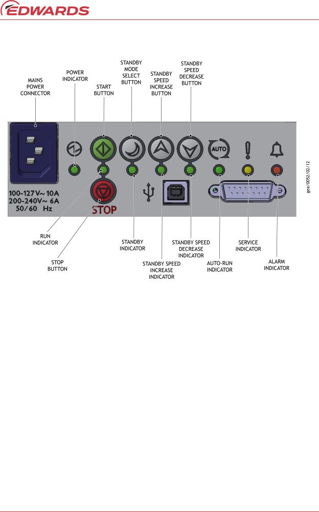
Figure 2 - Quick start guide (manual control mode)
A735-01-880 Issue F
<![if ! IE]><![endif]>Introduction
OPERATION |
SELECT |
STATUS |
SECTION |
|
|
|
|
|
|
Apply power |
MAINS |
The pump will remain off (factory default). |
3.6.2 |
|
POWER |
The POWER INDICATOR will illuminate. |
|||
|
|
|||
|
|
|
|
|
|
|
The pump will accelerate up to full running speed.* |
|
|
Start the pump |
START |
The RUN INDICATOR will flash while accelerating. |
4.2.1 |
|
BUTTON |
The RUN INDICATOR will remain on when the pump reaches |
|||
|
|
|||
|
|
full speed. |
|
|
|
|
|
|
|
|
|
The pump will decelerate and stop running. |
|
|
Stop the pump |
STOP BUTTON |
The RUN INDICATOR will flash while decelerating. |
4.2.1 |
|
|
|
The RUN INDICATOR will go off when the pump has stopped. |
|
|
|
|
|
|
|
Select and deselect |
STANDBY MODE |
When engaged, the STANDBY INDICATOR will illuminate and |
4.2.2 |
|
the standby speed |
SELECT BUTTON |
the pump will run at the standby speed setting. Factory |
||
default is 70% of full speed. |
|
|||
|
|
|
|
|
|
STANDBY SPEED |
The pump speed will increase. |
|
|
Increase or |
INCREASE |
The INCREASE STANDBY INDICATOR will remain illuminated |
4.2.2 |
|
decrease the pump |
BUTTON |
when the pump reaches a maximum of 100% of full speed. |
|
|
speed when in |
STANDBY SPEED |
The pump speed will decrease. |
|
|
standby mode |
DECREASE |
The DECREASE STANDBY INDICATOR will remain illuminated |
4.2.2 |
|
|
BUTTON |
when the pump reaches a minimum of 67% of full speed. |
|
|
|
|
|
|
|
Select and deselect |
START or STOP |
When engaged, the AUTO-RUN INDICATOR will illuminate. |
|
|
the Auto-run |
The pump will re-start automatically after the power has |
4.5 |
||
BUTTON (>8 sec) |
||||
function |
been restored. |
|
||
|
|
|
|
*The pump is set to 30 Hz rotational full speed (factory default)
© Edwards Limited 2018. All rights reserved. |
Page 5 |
A735-01-880 Issue F
<![endif]>Introduction
Table 1 - nXDS Control modes
Configuration |
Control mode |
Manual/Section |
|
|
|
|
Manual control |
Section 1 |
|
via |
Figure 2 |
|
nXDS user interface |
in this manual |
|
|
|
|
Serial control |
|
|
via (TIC) |
Manual |
|
*Turbo Instrument |
|
|
D397-22-880 |
|
|
Controller or |
|
|
|
|
|
Turbo Controller |
|
|
|
|
|
Parallel control |
|
|
via (TAG) |
Manual |
|
Turbo & Active Gauge |
D395-92-880 |
|
Controller |
|
|
|
|
|
Parallel control |
Section 1.4 |
|
via Digital I/O |
|
|
in this manual |
|
|
e.g. PLC control |
|
|
|
|
|
|
|
|
Parallel control |
|
|
via Digital I/O and |
Section 4.4 |
|
Analogue speed |
Figure 11 |
|
control source |
|
|
|
|
|
Serial control |
|
|
via RS232 or |
Manual |
|
RS485 Comms |
A735-01-860 |
|
Interface |
|
|
|
|
Note: Table 1 shows additional Edwards products, such as DX / nEXT Turbo pumps and active gauges that can be controlled at the same time using the various control methods displayed above.
Page 6 |
© Edwards Limited 2018. All rights reserved. |

A735-01-880 Issue F
2 Technical data
WARNING
If the nXDS pump is operated outside the specified limits, the pump housing may become hot.
2.1Operating and storage conditions
Table 2 - Operating and storage conditions
Operating and storage conditions |
|
nXDS |
|
|
|
Ambient temperature range (storage) |
|
–30 °C to +70 °C |
Ambient temperature range (operation) |
|
+5 °C to +40 °C |
Maximum humidity (storage in original packaging) |
|
95% RH |
Maximum humidity (operation) |
|
90% RH |
|
|
|
Table 3 - Environmental conditions |
||
|
|
|
Environmental conditions |
||
|
|
|
Pollution |
Pollution degree 2 |
|
Installation |
Installation category II |
|
Altitude restriction |
Max 2000 m* |
|
Area of use |
Indoor |
|
|
|
|
*The product can be used up to an altitude of 3000 m. However, the product is only ETL certified for use up to 2000 m.
2.2Performance
2.2.1General
Table 4 - General characteristics
Description |
nXDS6i |
nXDS10i |
nXDS15i |
nXDS20i |
|
|
|
|
|
|
|
Peak pumping speed (m3h-1) |
6.2 |
11.4 |
15.1 |
22.0 |
|
Maximum permitted continuous inlet pressure (mbar)* |
200 |
200 |
200 |
50 |
|
Maximum permitted exhaust pressure (bar gauge)† |
1 |
1 |
1 |
1 |
|
Maximum permitted gas ballast inlet pressure (bar gauge) |
0.5 |
0.5 |
0.5 |
0.5 |
|
|
|
|
|
|
|
Maximum recommended chamber volume to pump down |
25 |
50 |
75 |
75 |
|
from atmospheric pressure (litres)‡ |
|||||
|
|
|
|
||
Maximum pressure rise when stopped, with no inlet or gas |
7 |
7 |
7 |
7 |
|
ballast flow (mbar) |
|||||
|
|
|
|
||
|
|
|
|
|
|
Leak tightness (mbar ls-1) |
1 x 10⁻⁶ |
1 x 10⁻⁶ |
1 x 10⁻⁶ |
1 x 10⁻⁶ |
*These pumps are designed to pump down from atmospheric pressure, but prolonged operation at inlet
pressures higher than specified may reduce bearing life.
†These pumps are intended to exhaust to atmospheric pressure. High exhaust pressure may reduce tip-seal life.
‡Larger volumes may be pumped, but prolonged operation at inlet pressures higher than specified may reduce bearing life. The nXDS20i is optimised for constant throughput and is not recommended for cyclic duty.
<![endif]>data Technical
© Edwards Limited 2018. All rights reserved. |
Page 7 |

A735-01-880 Issue F
<![endif]>data Technical
Note: If the pump is operated outside the specified limits, then the pump housing may become hot; the controller may reduce the motor speed; and tip seal wear rate will be increased.
2.2.2Pumping media
WARNING
Do not use the nXDS pump to pump pyrophoric materials or dust.
The pump is designed to pump the following gases:
Air
Carbon dioxide
Helium
Carbon monoxide
Nitrogen
Argon
Oxygen (O2)
The pump can be used to pump water vapour. Caution must be taken to ensure that vapour does not condense inside the pump. Refer to Section 4.6.1 on how to prevent condensation of water vapour in the pump.
If pumping a vapour or gas not in the list above, contact Edwards for advice.
2.2.3Performance characteristics
The position of the gas ballast control defines the performance characteristics of the pump. These performance characteristics are listed in Table 5.
Table 5 - Performance characteristics
Description |
|
nXDS6i |
nXDS10i |
nXDS15i |
nXDS20i |
|
|
|
|
|
|
|
|
Pump ultimate |
Gas ballast position 0 |
2 x10⁻² |
7 x 10⁻³ |
7 x 10⁻³ |
3 x 10⁻² |
|
(mbar) |
Gas ballast position 1 |
5 x 10⁻² |
4 x 10⁻² |
4 x 10⁻² |
6 x 10⁻² |
|
Gas ballast flow |
Gas ballast position 1 |
12 |
16 |
31 |
24 |
|
(l min-1) |
||||||
|
|
|
|
|
Page 8 |
© Edwards Limited 2018. All rights reserved. |
Loading...