


 Loading...
B722-40-880
Issue E Original
Instruction Manual
EXT Compound Turbomolecular Pumps
EXT75DX, EXT75iDX, EXT255DX and EXT255iDX
Description |
|
Item Number |
|
|
|
EXT75DX |
ISO63 |
B722-41-000 |
EXT75DX |
CF63 |
B722-42-000 |
EXT75DX |
NW40 |
B722-43-000 |
EXT75DX |
ISO100 |
B722-45-000 |
EXT75DX |
ISO100 (NW25 Backing) |
B722-46-000 |
EXT75DX |
ISO63 Reversed |
B722-48-000 |
EXT75iDX |
NW40 |
B722-35-000 |
EXT75iDX |
ISO63 (NW16 Interstage) |
B722-37-000 |
EXT75iDX |
ISO63 (NW25 Interstage) |
B722-38-000 |
EXT255DX |
ISO100 |
B753-11-000 |
EXT255DX |
CF100 |
B753-12-000 |
EXT255iDX |
ISO100 (Interstage) |
B753-13-000 |
|
|
|

This page has been intentionally left blank.

|
|
|
B722-40-880 Issue E |
|
|
|
|
||
|
Contents |
|
||
|
Section |
Page |
||
|
1 |
Introduction ....................................................................................... |
1 |
|
|
1.1 |
Scope and definitions ................................................................................................... |
1 |
|
|
1.2 |
General description ..................................................................................................... |
1 |
|
|
1.3 |
Drive electronics ......................................................................................................... |
2 |
|
|
1.4 |
Operational features .................................................................................................... |
3 |
|
|
1.4.1 |
Power limit setting ...................................................................................................... |
3 |
|
|
1.4.2 |
Standby speed ............................................................................................................ |
3 |
|
|
1.4.3 |
Timer ...................................................................................................................... |
3 |
|
|
1.4.4 |
Analogue output ......................................................................................................... |
4 |
|
|
1.4.5 |
Automatic vent options ................................................................................................. |
4 |
|
|
1.4.6 |
Normal speed setting .................................................................................................... |
4 |
|
|
1.4.7 |
Electronic braking ....................................................................................................... |
5 |
|
|
1.5 |
Logic interface ........................................................................................................... |
5 |
|
|
1.5.1 |
Parallel control and monitoring ....................................................................................... |
5 |
|
|
1.5.2 |
Full serial control ........................................................................................................ |
6 |
|
|
1.5.3 |
Serial control with parallel monitoring ............................................................................... |
6 |
|
|
1.5.4 |
Parallel control with occasional serial monitoring or serial set-up .............................................. |
6 |
|
|
1.5.5 |
Podule configuration (serial set-up) .................................................................................. |
6 |
|
|
2 |
Technical data .................................................................................... |
7 |
|
|
2.1 |
General .................................................................................................................... |
7 |
|
|
2.2 |
Pumping media ........................................................................................................... |
7 |
|
|
2.3 |
Vent gas specification and vent control data ...................................................................... |
13 |
|
|
2.4 |
Purge gas specification ................................................................................................ |
14 |
|
|
2.5 |
Cooling water ............................................................................................................ |
14 |
|
|
2.6 |
Materials exposed to gases pumped ................................................................................. |
14 |
|
|
2.7 |
Electrical data ........................................................................................................... |
15 |
|
|
2.8 |
Logic interface connector ............................................................................................. |
15 |
|
|
2.9 |
Podule connector socket .............................................................................................. |
16 |
|
|
2.10 |
Indicator LEDs ........................................................................................................... |
18 |
|
|
2.11 |
Operating and storage environment ................................................................................. |
18 |
|
|
3 |
Installation ....................................................................................... |
19 |
|
|
3.1 |
Unpack and inspect ..................................................................................................... |
19 |
|
|
3.2 |
Typical installation ..................................................................................................... |
19 |
|
|
3.3 |
Connection to the vacuum system ................................................................................... |
19 |
|
|
3.3.1 |
Inlet-screen (supplied fitted) ......................................................................................... |
21 |
|
|
3.3.2 |
Mechanical fixing ....................................................................................................... |
22 |
|
|
3.3.3 |
Inlet-connection and orientation ..................................................................................... |
22 |
|
|
3.3.4 |
Base mounting ........................................................................................................... |
22 |
|
|
3.3.5 |
Backing connection ..................................................................................................... |
23 |
|
|
3.3.6 |
Interstage connection (iDX variants only) ........................................................................... |
23 |
|
|
3.4 |
Purge gas connection ................................................................................................... |
24 |
|
|
3.4.1 |
Connect the purge gas ................................................................................................. |
24 |
|
|
3.4.2 |
Recommended purge gas flow ........................................................................................ |
24 |
|
|
3.5 |
Electrical installation .................................................................................................. |
24 |
|
|
3.5.1 |
Introduction ............................................................................................................. |
24 |
|
|
3.5.2 |
Earth (ground) connections ........................................................................................... |
24 |
|
dcs/7590/09/07 |
3.5.3 |
Connect the logic interface to the TIC .............................................................................. |
24 |
|
3.5.4 |
Connect the logic interface to your control equipment |
24 |
||
|
||||
|
3.5.5 |
Connect the electrical supply ......................................................................................... |
25 |
|
|
3.6 |
Parallel interface mode ................................................................................................ |
26 |
|
|
|
|
||
|
© Edwards Limited 2007. All rights reserved. |
Page i |
||
|
Edwards and the Edwards logo are trademarks of Edwards Limited. |
|
||
Contents

B722-40-880 Issue E
Contents
3.7
3.7.1
3.7.2
3.7.3
3.7.4
3.7.5
3.7.6
3.7.7
3.8
3.8.1
3.8.2
3.8.3
3.8.4
3.9
3.9.1
3.9.2
3.9.3
Serial interface mode .................................................................................................. |
27 |
Connect the serial interface to your control equipment ......................................................... |
27 |
Serial enable ............................................................................................................. |
28 |
Serial protocol ........................................................................................................... |
28 |
Message structure ....................................................................................................... |
29 |
Command set ............................................................................................................ |
30 |
Simultaneous parallel and serial operation ......................................................................... |
30 |
Multi-drop mode ........................................................................................................ |
33 |
Vent options, vent valve connection and control .................................................................. |
34 |
Manual vent valve ...................................................................................................... |
34 |
TAV5 or TAV6 solenoid vent valve .................................................................................... |
34 |
Controlled venting ...................................................................................................... |
35 |
Alternative valve connected to the vacuum system .............................................................. |
35 |
Cooling ................................................................................................................... |
36 |
Introduction ............................................................................................................. |
36 |
Forced air cooling ....................................................................................................... |
36 |
Water-cooling ........................................................................................................... |
36 |
4 |
Operation ........................................................................................ |
39 |
4.1 |
Configuring the DX pump using serial commands .................................................................. |
39 |
4.1.1 |
Power limit setting ..................................................................................................... |
39 |
4.1.2 |
Powering a fan from the podule ...................................................................................... |
40 |
4.1.3 |
Controlled venting options ............................................................................................ |
40 |
4.1.4 |
Standby speed setting .................................................................................................. |
41 |
4.1.5 |
Normal speed setting ................................................................................................... |
41 |
4.1.6 |
Timer setting and options ............................................................................................. |
42 |
4.1.7 |
Analogue signal options ................................................................................................ |
43 |
4.1.8 |
Electronic braking options ............................................................................................. |
43 |
4.1.9 |
Factory settings ......................................................................................................... |
44 |
4.1.10 |
Assigning a multi-drop address ....................................................................................... |
44 |
4.2 |
Configuring the DX pump using a TIC ................................................................................ |
45 |
4.3 |
Start-up .................................................................................................................. |
45 |
4.3.1 |
Close the vent valve .................................................................................................... |
45 |
4.3.2 |
Pre-start checks ......................................................................................................... |
46 |
4.4 |
Operation with parallel control and monitoring ................................................................... |
46 |
4.4.1 |
Start the pump .......................................................................................................... |
46 |
4.4.2 |
Running at standby speed ............................................................................................. |
46 |
4.4.3 |
Stop the pump ........................................................................................................... |
46 |
4.4.4 |
Parallel monitoring ..................................................................................................... |
47 |
4.5 |
Operation with serial control and monitoring ...................................................................... |
47 |
4.5.1 |
Delayed start ............................................................................................................ |
47 |
4.5.2 |
Start the pump .......................................................................................................... |
47 |
4.5.3 |
Standby speed ........................................................................................................... |
47 |
4.5.4 |
Stop the pump ........................................................................................................... |
48 |
4.5.5 |
Temperature readings ................................................................................................. |
48 |
4.5.6 |
Link parameter readings ............................................................................................... |
48 |
4.5.7 |
Measured motor speed ................................................................................................. |
48 |
4.6 |
Simultaneous parallel and serial operation ......................................................................... |
49 |
4.7 |
Operation with a TIC ................................................................................................... |
49 |
4.8 |
Decelerating and venting .............................................................................................. |
49 |
4.9 |
Operation at extreme conditions ..................................................................................... |
49 |
4.9.1 |
Operation with high inlet pressure ................................................................................... |
49 |
4.9.2 |
Operation at high temperatures ...................................................................................... |
50 |
4.9.3 |
Operation at over-speed ............................................................................................... |
50 |
4.9.4 |
Electrical supply failure ............................................................................................... |
50 |
4.10 |
Bakeout ................................................................................................................... |
51 |
5 |
Maintenance ..................................................................................... |
53 |
5.1 |
Introduction ............................................................................................................. |
53 |
Page ii |
|
© Edwards Limited 2007. All rights reserved. |
|
Edwards and the Edwards logo are trademarks of Edwards Limited. |
|

|
|
B722-40-880 Issue E |
5.2 |
Bearing maintenance ................................................................................................... |
53 |
5.3 |
Rotor life ................................................................................................................. |
53 |
5.4 |
Clean the external surfaces of the pump ........................................................................... |
53 |
5.5 |
Fault finding ............................................................................................................. |
54 |
5.5.1 |
Flashing error codes .................................................................................................... |
56 |
5.5.2 |
Decoding system status words ........................................................................................ |
56 |
5.5.3 |
Useful service information ............................................................................................ |
59 |
6 |
Storage and disposal ........................................................................... |
61 |
6.1 |
Storage ................................................................................................................... |
61 |
6.2 |
Disposal ................................................................................................................... |
61 |
7 |
Service, spares and accessories .............................................................. |
63 |
7.1 |
Introduction ............................................................................................................. |
63 |
7.2 |
Service .................................................................................................................... |
63 |
7.2.1 |
Returning a pump for service ......................................................................................... |
63 |
7.3 |
Spares ..................................................................................................................... |
63 |
7.3.1 |
ISX inlet-screen ......................................................................................................... |
63 |
7.3.2 |
Inlet-strainer ............................................................................................................ |
64 |
7.3.3 |
Inlet-flange seals ........................................................................................................ |
64 |
7.4 |
Accessories ............................................................................................................... |
64 |
7.4.1 |
Installation ............................................................................................................... |
64 |
7.4.2 |
ACX air-cooler ........................................................................................................... |
64 |
7.4.3 |
WCX water-cooler ...................................................................................................... |
64 |
7.4.4 |
BX bakeout band ........................................................................................................ |
65 |
7.4.5 |
TAV vent-valve and vent-port adaptor .............................................................................. |
65 |
7.4.6 |
VRX vent-restrictor ..................................................................................................... |
65 |
7.4.7 |
Vent-port adaptor ...................................................................................................... |
65 |
7.4.8 |
PRX purge-restrictor .................................................................................................... |
66 |
7.4.9 |
Vibration isolators ...................................................................................................... |
66 |
7.4.10 |
FL20K foreline trap ..................................................................................................... |
66 |
7.4.11 |
Podule connector plug ................................................................................................. |
66 |
7.4.12 |
TIC turbo and instrument controllers ................................................................................ |
66 |
7.4.13 |
TIC PC Program .......................................................................................................... |
67 |
|
Index .............................................................................................. |
69 |
|
For return of equipment, complete the HS Forms at the end of this manual. |
|
Illustrations
Figure |
|
Page |
1 |
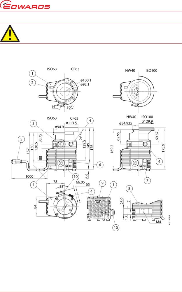
EXT75DX dimensions (mm) ............................................................................................ |
11 |
2 |
EXT255DX dimensions (mm) ........................................................................................... |
12 |
3 |
Maximum allowed rate of pressure rise during venting: pressure against time |
|
|
(with pump initially at full rotational speed) ...................................................................... |
13 |
4 |
Podule connector plug ................................................................................................. |
17 |
5 |
Typical pumping system with a DX pump ........................................................................... |
20 |
6 |
Correct installation of the inlet-screen (EXT75DX) ................................................................ |
21 |
7 |
Correct installation of the inlet-screen (EXT255DX) .............................................................. |
21 |
8 |
Logic interface connections - parallel mode ....................................................................... |
26 |
9 |
Logic interface connections - serial mode .......................................................................... |
27 |
10 |
Conceptual diagram for multi-drop connection .................................................................... |
29 |
11 |
Schematic diagram of the logic interface connections ........................................................... |
33 |
12 |
Installation of optional accessories and spares .................................................................... |
67 |
Contents
© Edwards Limited 2007. All rights reserved. |
Page iii |
Edwards and the Edwards logo are trademarks of Edwards Limited. |
|

B722-40-880 Issue E
Contents
Tables |
|
|
Table |
|
Page |
1 |
Power limits .............................................................................................................. |
3 |
2 |
General data .............................................................................................................. |
7 |
3 |
DX pumps technical data ............................................................................................... |
8 |
4 |
DX pumps technical data ............................................................................................... |
9 |
5 |
DX pumps technical data .............................................................................................. |
10 |
6 |
Vent gas specification and vent control ............................................................................. |
13 |
7 |
Purge gas specification ................................................................................................ |
14 |
8 |
Cooling water specification ........................................................................................... |
14 |
9 |
Logic interface technical data ........................................................................................ |
15 |
10 |
Logic interface connector pins ....................................................................................... |
17 |
11 |
Podule technical data .................................................................................................. |
17 |
12 |
Indicator LEDs ........................................................................................................... |
18 |
13 |
Operating and storage environment ................................................................................. |
18 |
14 |
Checklist of components ............................................................................................... |
19 |
15 |
Summary of commands that can be sent to the DX pump ........................................................ |
30 |
16 |
Command abbreviations ............................................................................................... |
32 |
17 |
Error codes ............................................................................................................... |
32 |
18 |
Vent options ............................................................................................................. |
35 |
19 |
Vent-restrictor orifice diameter (with atmospheric pressure at the inlet of the vent-valve) .............. |
35 |
20 |
Power limit setting ..................................................................................................... |
39 |
21 |
Analogue signal options ................................................................................................ |
43 |
22 |
Behaviour of a pump when the power is re-instated after an electrical supply failure ..................... |
52 |
23 |
Fault finding ............................................................................................................. |
54 |
24 |
Flashing error codes .................................................................................................... |
56 |
25 |
Hexadecimal conversion table ........................................................................................ |
57 |
26 |
Status flags .............................................................................................................. |
57 |
27 |
Example decoding of system status words .......................................................................... |
58 |
28 |
Inlet-flange seals ........................................................................................................ |
64 |
29 |
Vent restrictors ......................................................................................................... |
65 |
Trademark credits
Windows™ is trademark of Microsoft Corporation.
Page iv |
© Edwards Limited 2007. All rights reserved. |
|
Edwards and the Edwards logo are trademarks of Edwards Limited. |
B722-40-880 Issue E
1 Introduction
1.1Scope and definitions
This manual provides installation, operation, maintenance and storage instructions for the Edwards DX Compound Turbomolecular Pumps. You must use the DX pumps as specified in this manual. If you do not, the protection provided by the DX pumps may be impaired.
Read this manual before you install and operate the DX pump. Important safety information is highlighted as WARNING and CAUTION instructions; you must obey these instructions. The use of WARNINGS and CAUTIONS is defined below.
WARNING
Warnings are given where failure to observe the instruction could result in injury or death to people.
CAUTION
Cautions are given where failure to observe the instruction could result in damage to the equipment, associated equipment and process.
The units used throughout this manual conform to the SI international system of units of measurement. When flow rates are specified, the abbreviation ‘sccm’ is used to mean standard cubic centimetres per minute. This is a flow of 1 cm3 min-1 at an ambient temperature of 0 ºC and a pressure of 1013 mbar (1.013 x 10⁵ Pa).
In accordance with standard EN61010, the following warning label appears on the DX pump:
Warning - refer to accompanying documentation.
Warning - hot surfaces.
The units used throughout this manual conform to the SI international system of units of measurement; where appropriate US equivalent units of measurement are also given.
1.2General description
WARNING
Improper use of the equipment could cause damage to it or injury to people. The user is responsible for the safe operation, installation and monitoring of the system.
WARNING
The Podule contains electrolytic capacitors and, under certain fault conditions, may emit dangerous fumes. Ensure that the Podule is operated in a well-ventilated area.
Introduction
© Edwards Limited 2007. All rights reserved. |
Page 1 |
Edwards and the Edwards logo are trademarks of Edwards Limited. |
|

B722-40-880 Issue E
Introduction
CAUTION
Do not attempt to separate the Podule from the pump since this will cause damage to the electrical connections.
The DX pumps consist of the compound turbomolecular pump with a permanently attached Podule containing drive electronics.
The Podule controls the electrical supply to the pump. It has no manual controls and can only be operated through the logic interface. To operate the DX pump you must connect it to your own control equipment and power supply or alternatively use the Edwards TIC Turbo Instrument Controller or TIC Turbo Controller.
The Podule drives the brush-less d.c. motor in the pump. The pump has three Hall effect devices that operate as rotor position sensors and ensure that the drive current is correctly commutated around the motor phase-windings.
The vacuum pump contains turbomolecular blades and a Holweck drag mechanism on a single shaft; the Holweck mechanism allows operation at higher backing pressures than pure turbomolecular pumps.
DX pumps are supplied with an inlet-screen fitted into the bore of the inlet-flange. Both the EXT255iDX and the EXT75iDX with an NW25 interstage port are supplied with an inlet-strainer that fits into the interstage-port. The inletscreen and inlet-strainer protect the pump against damage that would be caused by debris entering the pump. The inlet-screen also protects the user against injury from the sharp blades in the pump.
Note: The EXT75iDX with an NW16 interstage port is not supplied with an inlet-strainer.
The DX pumps have a vent-port for venting the pump and vacuum system to atmospheric pressure. The pump is supplied with a manual vent-valve fitted; this can be replaced with a TAV5 or TAV6 solenoid-operated vent-valve (available as accessories – see Section 7).
The DX pumps have a purge-port: an inert purge gas can be introduced to protect the bearing and motor from corrosion, or the bearing lubricant from oxidisation. An optional vent-port adapter and purge restrictor can be fitted to the purge-port to control the flow rate of the purge gas and to filter the gas supply. (Refer to Section 7).
Air-coolers and a water-cooling block are available as optional accessories to cool the DX pumps. (Refer to Section 7).
1.3Drive electronics
The Podule contains the drive electronics that control the pump operation and accessories such as a TAV vent valve or air cooler. There is a connector socket on the top of the Podule where the TAV vent valve or air cooler can be plugged-in. (Refer to Section 2.9)
The Podule has two indicator LEDs that signal the status and operation of the pump, that can also be used for faultfinding if a problem should occur. (Refer to Section 2.10)
The drive electronics system has a number of built-in safety features to protect the DX pumps from damage in the event of sustained high pressure or temperature:
zThe electronics constantly monitor the temperature inside the Podule and the temperature of the motor within the pump. If either part becomes too hot, the electronics reduce the power supplied to the pump motor and the pump speed will drop. If the pump rotational speed falls below 50% full speed, the electronics may trip into Fail condition, depending on how you have configured the system. (Refer to Section 1.4.3).
zIf the DX pump's inlet pressure increases, the power supplied to the pump-motor increases to counteract the gas frictional load. However, when the built-in maximum power limit is reached, the speed of the pump will start to drop. If the pump rotational speed falls below 50% full speed, the electronics may trip into Fail condition, depending on how you have configured the system. (Refer to Section 1.4.3).
zIn the event of an electrical supply failure, the drive electronics uses the motor within the pump as a generator. This means the DX pumps have their own regenerative supply and do not require a separate battery for emergency power back-up. The regenerated energy is used to maintain the electrical supply to the connector socket on the Podule until the pump speed falls to below 50% of full rotational speed: this will ensure that the vent valve remains shut until below 50% of full rotational speed and will prevent the pump from venting at full speed, provided that there is not too much loading on the 24 V supply to the pump.
Page 2 |
© Edwards Limited 2007. All rights reserved. |
|
Edwards and the Edwards logo are trademarks of Edwards Limited. |
B722-40-880 Issue E
1.4Operational features
In addition to the basic start and stop commands, the DX pumps have several other features for improved functionality. This allows you to tailor the pump operation to your particular application. Refer to Table 15 for factory default settings of the parameters discussed in the following Sections.
1.4.1Power limit setting
You can select the maximum power that will be drawn by the pump (refer to Section 4.1.1). The more power you supply, the quicker the pump will accelerate to reach full speed. Therefore if your application requires fast cycling, you should set the power limit to the maximum value. If ramp time is not important in your application, you can use a lower power limit, down to a minimum value, refer to Table 1.
Table 1 - Power limits
Pump |
Maximum value setting |
Minimum value setting |
|
|
|
EXT75DX |
120 W |
50 W |
EXT255DX |
200 W |
80 W |
|
|
|
You must make sure that the power supply you use is capable of delivering sufficient power to the DX pump. By choosing a lower power limit setting, you could use a smaller power supply. For more information, refer to Section 2.7.
1.4.2Standby speed
In Standby mode the pump rotational speed is lower than the full rotational speed.
If your application does not require the pump to be running at maximum speed at all times, you can use the Standby speed feature rather than switching the pump off. This can save you time since you do not have to stop or vent the pump and you do not have to wait as long for the pump to accelerate back to full speed.
The Standby speed is a user-selectable value (refer to Section 4.1.4).
1.4.3Timer
When the pump is started, an internal timer is automatically started within the drive electronics. If the pump fails to reach 50% of full rotational speed within the timeout period, the Podule will signal a Fail and will decelerate the pump to rest. This is a safety feature and prevents the Podule driving the pump at maximum power for a long time, which could cause damage. The pump may fail to reach 50% speed if the gas load is too high (for example if there is a leak in the system), if the backing pump fails, or if the pump is too hot.
The timeout period is a user-selectable feature (refer to Section 4.1.6), so if your application requires the pump to ramp up slowly, you can extend the timeout period. The Timer is permanently enabled for ramp-up.
The Timer has an additional function: if the pump rotational speed drops below 50% full speed for any reason, you may wish to allow the pump time to recover rather than trigger a Fail condition. The Timer starts as soon as the speed drops to below 50% full speed. If, during the timeout period, the pump recovers to above 50% full speed then the Timer will be reset. If the pump rotational speed fails to recover by the end of the timeout period, the Podule will trigger a Fail condition and will decelerate the pump to rest. When you receive the pump, the Timer function will be enabled, however you can disable it if you wish to. With the Timer disabled, the pump will Fail and decelerate to rest as soon as pump rotational speed falls below 50%.
Introduction
© Edwards Limited 2007. All rights reserved. |
Page 3 |
Edwards and the Edwards logo are trademarks of Edwards Limited. |
|

B722-40-880 Issue E
Introduction
1.4.4Analogue output
The Podule produces an analogue output that allows you to monitor four different system parameters:
zMeasured pump rotational speed
zMeasured motor power
zMeasured motor temperature
zMeasured controller temperature
The analogue output signal ranges from 0 to 10 V and is directly proportional to the system parameter (refer to Section 2.8).
Connect the analogue output to a suitable meter or indicator to display the appropriate system parameter or connect to your control equipment (for example, to operate other components in the pumping system at preset values).
You can only monitor one system parameter at a time using the analogue output. However, it is easy to configure the Podule to monitor a different system parameter (refer to Section 4.1.7).
1.4.5Automatic vent options
An Edwards TAV vent valve can be connected directly to the DX pump’s Podule. The Podule is capable of controlling a number of different venting options.
The drive electronics can control the rate of venting. Using this feature the pump can be vented from full rotational speed in a controlled manner that will not damage the pump bearings. Once the pump rotational speed has dropped to below 50% of maximum speed, it is safe to hard vent (open the vent valve fully.)
There are many venting options available to you, such as:
zHard vent when rotational speed drops below 50%
zControlled vent when above 50% speed and hard vent below 50% speed
zHard vent immediately through a suitable restrictor
A full list of the venting options is given in Section 3.8.
In addition there is a feature that allows a delayed start of the DX pump. With this feature you can close the vent valve before you start the DX pump. This allows the backing pump to reduce the pressure in the vacuum system before starting the DX pump.
If you do not wish to use the Podule to control a TAV vent valve, you could use it to run a fan instead. You can configure the Podule so that the fan is permanently enabled.
1.4.6Normal speed setting
The Normal Speed is a user-selectable parameter that can be set anywhere from 50% to 100% of full rotational speed. When the pump reaches Normal Speed, a signal is available on the Normal pin of the logic interface connector. You can use this signal to control your application since it shows that pump speed, and therefore vacuum performance, has reached a minimum specific level. The default setting is 80% of full rotational speed. Refer to Section 4.1.5 for instructions on altering the Normal Speed setting.
Page 4 |
© Edwards Limited 2007. All rights reserved. |
|
Edwards and the Edwards logo are trademarks of Edwards Limited. |

B722-40-880 Issue E
1.4.7Electronic braking
The pump has a user selectable Electronic Braking option, which is disabled by default. With this option disabled the pump will draw power from the supply when accelerating and running and will coast down when decelerating.
The Electronic Braking function may be enabled to reduce the pump deceleration time and to recover some energy from the pump. This is achieved by returning power from the pump to the electrical supply. The rate at which electrical energy is returned to the supply is regulated so as to limit the supply voltage to 24 V +10%. In order to achieve the fastest electronic braking times there must be somewhere for the returned power to go such as:
za supply capable of receiving the returned power
zother devices sharing the 24 V bus with the pump
za load resistor of approximately 10 Ω switched across the 24 V supply when decelerating the pump
1.5Logic interface
The Podule can only be operated through the logic interface. The signals on the logic interface are of three types:
zControl inputs: these are switch-type signals that are used to control the pump
zStatus outputs: these outputs identify the status of the system
zAnalogue output: this provides a 0 – 10 V output for a number of pump parameters.
The logic interface has been designed to include both serial and parallel modes of control and monitoring, operating through one connector. The pump can be operated using either serial or parallel method or some combination of the two.
The logic interface can be plugged directly into the Edwards TIC Turbo Controller or TIC Turbo Instrument Controller and then use the functionality that they provide. Alternatively, the logic interface can be connected to a customers own control system. The most useful arrangements are described in the sections below.
For more information about the logic interface, refer to Section 2.8.
1.5.1Parallel control and monitoring
The simple parallel interface is a quick and easy way to control the pump; this is the same interface used on existing 24V Edwards Turbo Pumps. The controls that are available to use are Start and Standby. You can monitor the system status using the Normal, Fail and Analogue output signals.
Note: The Serial Enable switch MUST be open (no connection).
Refer to Section 3.6 for more detailed instructions of how to use the parallel interface.
A system operating in pure parallel mode has no facility to adjust the configuration settings stored in the Podule (for example, power limit setting or controlled venting options). This would place a restriction in that all these features would be at their factory default settings. However, the Podule could be configured separately before fitting the DX pump to the system. This is covered in more detail in Section 1.5.5.
Introduction
© Edwards Limited 2007. All rights reserved. |
Page 5 |
Edwards and the Edwards logo are trademarks of Edwards Limited. |
|

B722-40-880 Issue E
Introduction
1.5.2Full serial control
The serial communications link provides complete control and monitoring using just three signal lines. The Serial data RX and TX use the same connector pins as the parallel signals Standby and Fail respectively.
The Serial Enable signal MUST be linked to 0 V for the system to accept commands in Serial control mode. This is a safety feature and acts as an interlock. In addition, the parallel Start signal must be left unconnected for Serial commands to be accepted in full Serial control mode.
The Podule will still provide the Normal and Analogue signals on the logic interface connector even when operating in full Serial control mode. The status of the Normal signal can also be obtained by interrogating the system status via the Serial interface.
For more information about the Serial interface, refer to Section 3.7.
1.5.3Serial control with parallel monitoring
Since Normal and Analogue signals remain available even using Serial control mode, it is possible to control the pump via the Serial interface whilst monitoring these signals using a parallel link.
Again, the Serial data RX and TX use the same connector pins as the parallel signals Standby and Fail respectively so these parallel control and monitoring signals are not available. The Serial Enable signal MUST be linked to 0 V and the Start switch must remain open (no connection).
1.5.4Parallel control with occasional serial monitoring or serial set-up
This method of control is best for users who normally wish to operate the pump in parallel mode but occasionally want to adjust the configuration settings stored in the Podule or to monitor operational status of the pump.
Whilst operating in Parallel mode, the same controls and monitoring signals are available as described in
Section 1.5.1. It must be remembered that the Serial data RX shares the same connector pin as the Standby signal so the pump cannot be commanded into Standby speed using this line.
The Serial Enable signal must be linked to 0 V for serial communications to take place. We suggest that you make a special cable for serial communications that includes a link between Serial Enable and 0 V. This way, Serial Enable is automatically activated when the cable is connected and then deactivated when the cable is removed.
1.5.5Podule configuration (serial set-up)
All the configuration settings stored within the Podule are retained even when power to the DX pump is removed. This means that it is possible to use a separate system to configure the Podule before fitting the DX pump to your application. This gives the benefit of tailoring the pump functionality to a customer application and allows the pump to be operated using a simple parallel interface system.
To configure the DX pump, either use your own simple serial system or use the Edwards TIC Turbo Controller or Turbo Instrument Controller. The TICs have a feature which allows storage of a DX pump’s configuration. The configuration can then be downloaded to another DX pump. This is useful when configuring a number of DX pumps with the same settings before they are fitted to a system.
The TIC is supplied with a WindowsTM based PC program which allows the DX pump to be configured from a single PC. The program has a simple user interface which means that it is not necessary to use the ASCII message protocol described in Section 3.7. The TIC PC Program has a facility to save multiple DX pump configurations which can then be downloaded into other DX pumps.
Page 6 |
© Edwards Limited 2007. All rights reserved. |
|
Edwards and the Edwards logo are trademarks of Edwards Limited. |
B722-40-880 Issue E
2 Technical data
2.1General
|
|
Table 2 - General data |
|
|
|
|
|
General items |
|
Reference data |
|
|
|
|
|
Performance |
|
Refer to Table 3 |
|
Dimensions |
|
|
Refer to Figure 1 and 2 |
Maximum inlet-flange temperature |
|
|
|
ISO63 / ISO100 / NW40 |
|
70 °C with cooling water |
|
DN63CF (EXT75DX) / DN100CF (EXT255DX) |
|
100 °C bakeout, with cooling water |
|
Maximum permitted external magnetic field |
|
|
|
EXT255DX |
|
3.5 mT horizontal field, 7 mT vertical field |
|
EXT75DX |
|
5 mT |
|
Pollution degree |
|
CAN/CSA, UL, EN61010 part 1 |
|
Equipment type |
|
Fixed equipment, for indoor use only |
|
Enclosure protection (installed) |
|
|
|
EXT255DX and 255iDX |
|
IP50 |
|
EXT75DX and 75iDX/NW25 |
|
IP50 |
|
EXT75iDX/NW16 |
|
IP50 |
|
|
|
|
|
2.2 |
Pumping media |
|
|
WARNING
Vent dangerous gases and gas mixtures safely, do not expose people to these gases. If pumping hazardous gases or vapours, observe the safety recommendations of the supplier of the gas/ vapour.
WARNING
Do not use the DX pump to pump pyrophoric or explosive gas mixtures, as it is not suitable for this purpose. The pump and its connections are not designed to contain an explosion.
WARNING
In the interstage versions of the DX pumps, gas pumped through the interstage port will mix with gas pumped through the pump inlet. Ensure that the gases will not react or combine to form dangerous gases and substances.
WARNING
Do not expose any part of the human body to vacuum.
data Technical
© Edwards Limited 2007. All rights reserved. |
Page 7 |
Edwards and the Edwards logo are trademarks of Edwards Limited. |
|

B722-40-880 Issue E
data Technical
CAUTION
Do not use the DX pump to pump gases containing more than 20% oxygen unless the pump is gas purged. If you do, the lubricant will polymerise and the pump may fail prematurely.
CAUTION
Do not use a DX pump to pump mercury vapour and do not allow mercury (for example, from a McLeod gauge) to come into contact with the pump. If you do, the pump rotor may corrode and fail.
Note: Concentrations of gases may be modified by the compression of the pump.
The pumps are designed to pump the following residual gases normally used in high-vacuum systems:
z |
Air |
z |
Carbon dioxide |
z |
Methane |
z |
Neon |
z |
Propane |
z |
Krypton |
z |
Butane |
z |
Helium |
z |
Carbon monoxide |
z |
Ethane |
z |
Nitrogen |
z |
Argon |
zHydrogen
You can use the pump to pump oxygen and water vapour, subject to the following conditions:
zOxygen – when the pump is purged by an inert gas, oxygen can be pumped at concentrations above 20% by volume. Refer to Section 2.4 for Purge gas specification. However, if the pump is not purged, the oxygen concentration must be less than 20% by volume.
zWater vapour - you must ensure that vapour does not condense inside the pump; refer to Section 3.9.3.
If you wish to pump a gas not in the list above, contact your supplier for advice. If you do not contact your supplier, you may invalidate the warranty on the pump. The pump is not suitable for pumping aggressive or corrosive gases.
Table 3 - DX pumps technical data
Parameter |
EXT75DX |
EXT75DX |
EXT75DX |
EXT75DX |
|
ISO63 |
63CF |
NW40 |
ISO100 |
||
|
|||||
|
|
|
|
|
|
Mass |
3.0 kg |
4.9 kg |
2.9 kg |
3.2 kg |
|
Inlet-flange |
DN63ISO-K |
DN63CF |
DN40NW |
DN100ISO-K |
|
Outlet-flange |
DN16NW |
DN16NW |
DN16NW |
DN16NW |
|
Vent-port |
1/8 inch BSP |
1/8 inch BSP |
1/8 inch BSP |
1/8 inch BSP |
|
Purge-port |
1/8 inch BSP |
1/8 inch BSP |
1/8 inch BSP |
1/8 inch BSP |
|
Interstage-port (optional) |
DN25NW and |
- |
- |
- |
|
|
DN16NW |
|
|
|
|
Inlet pumping speed |
|
|
|
|
|
N |
61 l s-1 |
61 l s-1 |
42 l s-1 |
66 l s-1 |
|
2 |
|
|
|
|
|
He |
57 l s -1 |
57 l s-1 |
49 l s-1 |
59 l s-1 |
|
H |
53 l s-1 |
53 l s-1 |
48 l s-1 |
54 l s-1 |
|
2 |
|
|
|
|
|
Inlet compression ratio |
|
|
|
|
|
N2 |
>1 x 10¹¹ |
>1 x 10¹¹ |
>1 x 10¹¹ |
>1 x 10¹¹ |
|
He |
1 x 10⁶ |
1 x 10⁶ |
1 x 10⁶ |
1 x 10⁶ |
|
H2 |
5 x 10⁴ |
5 x 10⁴ |
5 x 10⁴ |
5 x 10⁴ |
Page 8 |
© Edwards Limited 2007. All rights reserved. |
|
Edwards and the Edwards logo are trademarks of Edwards Limited. |

B722-40-880 Issue E
Table 3 - DX pumps technical data (continued)
Parameter |
EXT75DX |
EXT75DX |
EXT75DX |
EXT75DX |
|
ISO63 |
63CF |
NW40 |
ISO100 |
||
|
|||||
|
|
|
|
|
|
Interstage pumping speed, for interstage |
|
|
|
|
|
DX pumps with N2 (DN16NW port) |
|
|
|
|
|
70 sccm flow through interstage-port |
10 l s-1 |
- |
- |
- |
|
5 sccm flow through interstage-port |
3 l s-1 |
- |
- |
- |
|
Interstage pumping speed, for |
|
|
|
|
|
N2 |
- |
- |
- |
- |
|
He |
- |
- |
- |
- |
|
Ultimate pressure: |
|
|
|
|
|
with rotary vane backing pump:* |
<5 x 10⁻⁹ mbar |
<5 x 10⁻¹⁰ mbar |
<5 x 10⁻⁹ mbar |
<5 x 10⁻⁹ mbar |
|
with diaphragm backing pump:† |
<5 x 10⁻⁸mbar |
<5 x 10⁻⁹ mbar |
<5 x 10⁻⁸ mbar |
<5 x 10⁻⁸ mbar |
*Ultimate pressure 48 hours after bakeout with 2-stage rotary vane backing-pump.
†Ultimate pressure 48 hours after bakeout with Pb < 5 mbar (500 Pa).
Table 4 - DX pumps technical data
Parameter |
EXT255DX ISO100 |
EXT255iDX ISO100 |
EXT255DX |
|
100CF |
||||
|
|
|
||
|
|
|
|
|
Mass |
6.25 kg |
6.25 kg |
8.5 kg |
|
Inlet-flange |
DN100ISO-K |
DN100ISO-K |
DN100CF |
|
Outlet-flange |
DN25NW |
DN25NW |
DN25NW |
|
Vent-port |
1/8 inch BSP |
1/8 inch BSP |
1/8 inch BSP |
|
Purge-port |
1/8 inch BSP |
1/8 inch BSP |
1/8 inch BSP |
|
Interstage-port (optional) |
- |
DN25NW |
- |
|
Inlet pumping speed |
|
|
|
|
N2 |
220 l s-1 * |
220 l s-1 * |
220 l s-1 * |
|
He |
230 l s-1 * |
230 l s-1 * |
230 l s-1 * |
|
H2 |
180 l s-1 * |
180 l s-1 * |
180 l s-1 * |
|
Inlet compression ratio |
|
|
|
|
N |
>1 x 10⁸ |
>1 x 10⁸ |
>1 x 10⁸ |
|
2 |
|
|
|
|
He |
4 x 10⁵ |
3 x 10⁵ |
4 x 10⁵ |
|
H |
1 x 10⁴ |
1 x 10⁴ |
1 x 10⁴ |
|
2 |
|
|
|
|
Interstage pumping speed, for |
|
|
|
|
interstage DX pumps with N2 |
|
|
|
|
70 sccm flow through interstage-port |
- |
- |
- |
|
5 sccm flow through interstage-port |
- |
- |
- |
|
Interstage pumping speed, for |
|
|
|
|
N2 |
- |
10 l s-1 |
- |
|
He |
- |
8 l s-1 |
- |
|
Ultimate pressure: |
|
|
|
|
with rotary vane backing pump: † |
<5 x 10⁻⁹ mbar |
<5 x 10⁻⁹ mbar |
<5 x 10⁻¹⁰ mbar |
|
|
(DN100ISO-K inlet- |
(DN100ISO-K inlet- |
(DN100CF inlet-flange) |
|
|
flange) |
flange) |
|
|
|
|
|
|
data Technical
© Edwards Limited 2007. All rights reserved. |
Page 9 |
Edwards and the Edwards logo are trademarks of Edwards Limited. |
|

B722-40-880 Issue E
data Technical
Table 4 - DX pumps technical data (continued)
Parameter |
EXT255DX ISO100 |
EXT255iDX ISO100 |
EXT255DX |
|
100CF |
||||
|
|
|
||
|
|
|
|
|
with diaphragm backing pump: ‡ |
<5 x 10⁻⁸ mbar |
<5 x 10⁻⁸ mbar |
<5 x 10⁻⁹ mbar |
|
|
(DN100ISO-K inlet- |
(DN100ISO-K inlet- |
(DN100CF inlet-flange) |
|
|
flange) |
flange) |
|
|
|
|
|
|
*Pumping speeds are without inlet-screen or inlet-strainer. Inlet-screens and inlet-strainers reduce speed by approximately 10%.
†Ultimate pressure 48 hours after bakeout with 2-stage rotary vane backing-pump
‡Ultimate pressure 48 hours after bakeout with Pb < 5 mbar (500 Pa).
Table 5 - DX pumps technical data
Parameter |
EXT75DX |
EXT255DX |
|
|
|
Critical backing pressure * |
|
|
N2 |
8 mbar |
12 mbar |
He |
6.5 mbar |
9 mbar |
H2 |
2.5 mbar |
2.5 mbar |
Minimum backing pump displacement |
0.6 m3 h-1 |
0.6 m3 h-1 |
Maximum Continuous Backing Pressure † |
|
|
(at Ultimate Inlet Pressure) |
|
|
Nitrogen: |
|
|
Water Cooling (40 °C ambient) ‡ |
4 mbar |
7 mbar |
Forced Air Cooling (35 °C ambient) |
5 mbar |
5 mbar |
Natural Convection Cooling (30 °C ambient) |
2 mbar |
2 mbar |
|
|
|
Maximum continuous inlet pressure † |
|
|
(at Ultimate Backing Pressure) |
|
|
Nitrogen: |
|
|
Water cooling (40 ºC ambient) ‡ |
2 x 10⁻² mbar |
1 x 10⁻² mbar |
Forced Air cooling at (35 ºC ambient) |
3 x 10⁻² mbar |
8 x 10⁻³ mbar |
Natural Convection Cooling (30 °C ambient) |
8 x 10⁻³ mbar |
2 x 10⁻³ mbar |
Argon: |
|
|
Water cooling (40 ºC ambient) ‡ |
4 x 10⁻³ mbar |
7 x 10⁻³ mbar |
Forced Air cooling at (35 ºC ambient) |
4 x 10⁻³ mbar |
5 x 10⁻³ mbar |
Natural Convection Cooling (30 °C ambient) |
1 x 10⁻³ mbar |
1 x 10⁻³ mbar |
Recommended backing pump ** |
RV3 |
RV12 |
Operating attitude |
Vertical and upright |
Vertical and upright |
|
through to horizontal ± 2 ° |
through to horizontal ± 2 ° |
|
|
|
Nominal rotational speed |
90,000 revolutions per |
60,000 revolutions per |
|
minute |
minute |
|
|
|
Starting time to 90% speed †† |
110 seconds |
78 seconds |
Sound power level (1 metre away) |
< 50 dB(A) |
<50 dB(A) |
|
|
|
*Pumping speed is reduced to 90% of its original value.
†Above this pressure, rotational speed drops below nominal. Values for maximum continuous inlet pressure
obtained using a RV12 backing pump. Refer to Section 3.9 for cooling conditions.
‡Cooling water temperature at 15 °C. Cooling water flow rate at 30 l hr-1.
** |
A suitable diaphram pump with ultimate <5 mbar may also be used. |
†† |
Power limit setting 80 W (EXT75DX), 160 W (EXT255DX). |
Page 10 |
© Edwards Limited 2007. All rights reserved. |
|
Edwards and the Edwards logo are trademarks of Edwards Limited. |
B722-40-880 Issue E
WARNING
Do not exceed the maximum continuous operating pressure. Doing so can result in dangerous rotor temperatures and will shorten the life of the pump.
Figure 1 - EXT75DX dimensions (mm)
data Technical
1. |
Podule |
6. |
Purge port (blanked off) |
2. |
Podule connector socket (for fan/TAV valve) |
7. |
Earth connection |
3. |
Interstage port (EXT75iDX only) |
8. |
Cooling block mounting face |
4. |
Manual vent valve in vent port |
9. |
Podule indicator LEDs |
5. |
Logic interface connector |
10. Backing port |
|
© Edwards Limited 2007. All rights reserved. |
Page 11 |
Edwards and the Edwards logo are trademarks of Edwards Limited. |
|
B722-40-880 Issue E
data Technical
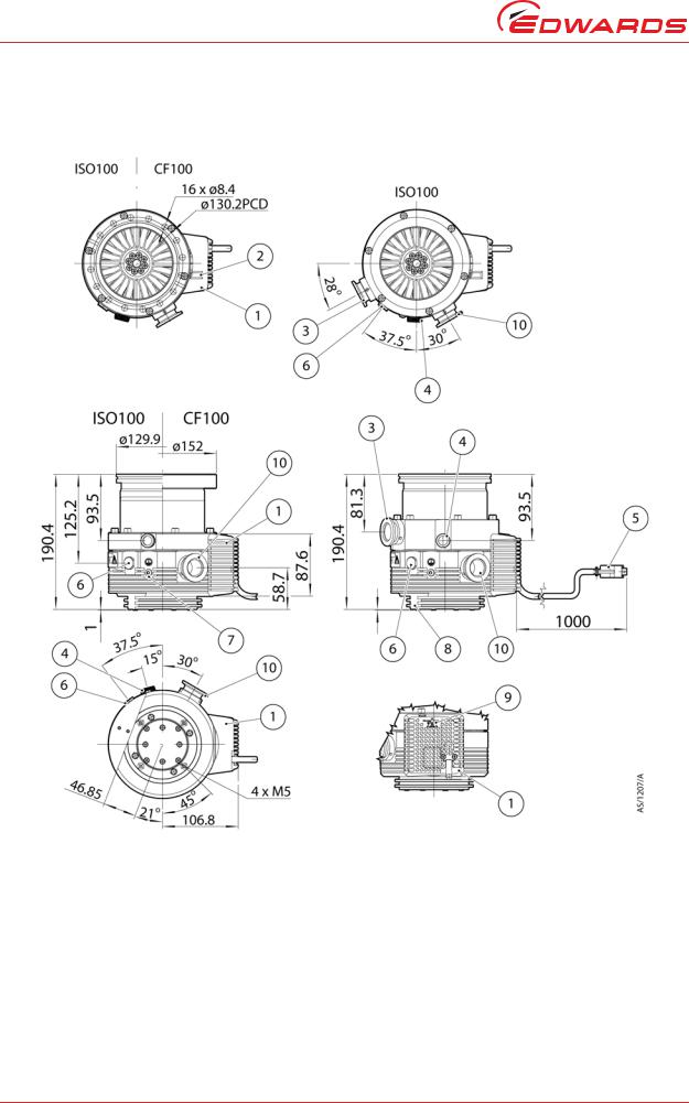
Figure 2 - EXT255DX dimensions (mm)
1. |
Podule |
6. |
Purge port (blanked off) |
2. |
Podule connector socket (for fan/TAV valve) |
7. |
Earth connection |
3. |
Interstage port (EXT255iDX only) |
8. |
Cooling block mounting frame |
4. |
Manual vent valve in vent port |
9. |
Podule indicator LEDs |
5. |
Logic interface connector |
10. Backing port |
|
Page 12 |
© Edwards Limited 2007. All rights reserved. |
|
Edwards and the Edwards logo are trademarks of Edwards Limited. |
B722-40-880 Issue E
2.3Vent gas specification and vent control data
Although the pump may be vented to atmosphere, high relative humidity of the air may greatly increase the subsequent pump-down time. To reduce pump-down times you should vent with dry, clean gases. Refer to Section 3.8 for a description of the vent options and the vent valve connection and refer to Section 4.1.3 for configuring the venting options.
Table 6 - Vent gas specification and vent control
Vent gas specification and control |
Reference data |
|
|
Vent gas |
Dry air, nitrogen, argon or other inert gases |
Maximum dew point at atmospheric pressure |
-22 °C |
Maximum size of particulates |
1 µm |
Maximum concentration of oil |
0.1 parts per million |
Recommended time for rotational speed to reach 50% |
> 15 seconds |
Maximum allowed rate of pressure rise |
Refer to Figure 3 |
|
|
Figure 3 - Maximum allowed rate of pressure rise during venting: pressure against time (with pump initially at full rotational speed)
data Technical
© Edwards Limited 2007. All rights reserved. |
Page 13 |
Edwards and the Edwards logo are trademarks of Edwards Limited. |
|

B722-40-880 Issue E
data Technical
2.4Purge gas specification
Table 7 - Purge gas specification
Purge gas specification |
Reference data |
|
|
|
|
Purge gas |
Dry air, nitrogen, argon or other inert gases |
|
Maximum dew point at atmospheric pressure |
-22 °C |
|
Maximum size of particulates |
1 µm |
|
Maximum concentration of oil |
0.1 parts per million |
|
Allowable purge gas flow (when required) |
20 to 50 sccm (0.33 to 0.84 mbar l s-1 or 33 to 84 Pa l s-1) |
|
Recommended purge gas flow |
25 sccm (0.42 mbar l s-1, 42 Pa l s-1) |
|
Maximum allowable purge gas supply pressure |
2 bar (gauge); 29 psi, 3 x 10⁵ Pa |
|
Table 8 - Cooling water specification |
||
|
|
|
Cooling water specification |
|
Reference data |
|
|
|
Quality |
|
Mechanically clean and optically clear with no deposits |
|
|
or turbidity |
pH value |
|
6.0 to 8.0 |
Maximum calcium carbonate concentration |
|
75 parts per million |
Maximum chloride concentration |
|
100 parts per million |
Minimum oxygen concentration |
|
4 parts per million |
Minimum cooling water flow rate (at 15 °C) |
|
15 l hr-1 |
Water temperature |
|
Refer to Table 5 |
Maximum water pressure |
|
5 bar (gauge), 73.5 psig, 6 x 10⁵ Pa |
Materials exposed to cooling-water |
|
Nickel plated brass |
|
|
|
2.5Cooling water
The above cooling water specification corresponds to a typical high-quality drinking water specification. Check with your water supply authority if you are in doubt about the quality of your supply.
2.6Materials exposed to gases pumped
The following materials and component types are exposed to the gases pumped:
Aluminium alloys, stainless steels, fluoroelastomer and nitrile O-rings, hydrocarbon lubricant, felt, rare earth magnets, silicon nitride, phenolic resin, carbon-fibre reinforced epoxy resin, fire retardant polypropylene, polyamide and PVC.
Page 14 |
© Edwards Limited 2007. All rights reserved. |
|
Edwards and the Edwards logo are trademarks of Edwards Limited. |

B722-40-880 Issue E
2.7Electrical data
DX pumps can be driven either by your own system or by the Edwards TIC Turbo Instrument Controller or TIC Turbo Controller.
If you wish to use your own system, the size of the power supply you must use depends on your application. The power limit setting determines how quickly you can ramp up the pump and dictates the size of power supply you will need. If you have serial communications capability, or have access to an Edwards TIC, you can select the power limit setting of the DX pump. Refer to Table 9 for the maximum and minimum power limit settings for DX pumps and for the associated maximum input current requirements. If your application requires rapid cycling of the pump, you can achieve faster ramp times if you use a power supply that delivers higher current, up to a maximum in accordance with Table 9.
If you do not have the facility to adjust the power limit setting, you must use a power supply capable of delivering enough current to meet the Edwards factory default power limit setting, shown in Table 9. For the EXT75DX this would be around 4 amps and for the EXT255DX it would be around 7 amps.
If you intend to drive the DX pump using an Edwards TIC, be aware that there are several variants. Contact Edwards to determine which is most suitable for your application.
2.8Logic interface connector
DX pumps have a 15-way logic interface connector on the end of the logic interface cable (see Figure 1 and 2, items 11 and 3 respectively). The logic interface connector can be plugged directly into the Edwards TIC Turbo Instrument Controller or TIC Turbo Controller. You must use a suitable connector mating half (not supplied) to connect the DX pump to your own equipment. Refer to Table 9 for the connector mating half type and to Table 10 for Logic Interface connector pins for the electrical connections.
Table 9 - Logic interface technical data
Logic interface item |
EXT75DX |
EXT255DX |
|
|
|
Connector * |
15-way D-type male |
15-way D-type male |
DX pumps electrical supply: |
|
|
Allowable voltage range |
24 V d.c. +5%, -10% |
24 V d.c. +5%, -10% |
(including any ripple) |
(21.6 to 25.2 V d.c.) |
(21.6 to 25.2 V d.c.) |
Maximum voltage ripple |
0.5 V r.m.s. |
0.5 V r.m.s. |
Maximum input current with |
<6 A at 24 V during ramp |
<10 A at 24 V during ramp |
maximum power limit setting |
|
|
Maximum input current with |
<3 A at 24 V |
<5 A at 24 V |
minimum power limit setting |
|
|
Fuse (or equivalent current |
6 A type 'T' IEC approved or |
10 A type 'T' IEC approved or |
limiting device) rating |
6 A time delay fuse UL/CSA approved |
10 A time delay fuse UL/CSA |
|
|
approved |
Factory default setting |
80 W |
160 W |
Maximum power limit |
120 W |
200 W |
Minimum power limit |
50 W |
80 W |
|
|
|
Hardware control input signal: |
|
|
Enabled control voltage: low |
0 to 0.8 V d.c. (Iout = 0.55 mA |
0 to 0.8 V d.c. (Iout = 0.55 mA |
(close) |
nominal) |
nominal) |
Disabled control voltage: high |
4 to 26.4 V d.c. (Internal pull up to |
4 to 26.4 V d.c. (Internal pull up to |
(open) |
6.35 V nominal) |
6.35 V nominal) |
|
|
|
data Technical
© Edwards Limited 2007. All rights reserved. |
Page 15 |
Edwards and the Edwards logo are trademarks of Edwards Limited. |
|

B722-40-880 Issue E
data Technical
Table 9 - Logic interface technical data (continued)
Logic interface item |
EXT75DX |
EXT255DX |
|
|
|
Analogue output: |
|
|
Output voltage |
0 to 10 V d.c. (directly proportional |
0 to 10 V d.c. (directly proportional |
|
to measured parameter) |
to measured parameter) |
|
Motor speed: 0 - 1500 Hz (0-100%) |
Motor speed: 0 - 1000 Hz (0-100%) |
|
Motor power: 0 - 120 W |
Motor power: 0 - 200 W |
|
Motor temperature: 0 - 100 °C |
Motor temperature: 0 - 100 °C |
|
Controller temperature: 0 - 100 °C |
Controller temperature: 0 - 100 °C |
Output current |
≤ 5 mA |
≤ 5 mA |
|
|
|
NORMAL status output: |
|
|
Type |
Open collector transistor |
Open collector transistor |
< Normal speed (default 80%) |
Off (2.2 kΩ pull up to 12 V d.c.) |
Off (2.2 kΩ pull up to 12 V d.c.) |
≥ Normal speed |
On (<0.8 V d.c. sinking 20 mA) |
On (<0.8 V d.c. sinking 20 mA) |
Rating |
20 mA to 0 V |
20 mA to 0 V |
|
|
|
FAIL status output: |
|
|
Type |
Open collector transistor |
Open collector transistor |
Fail |
Off (3.3 kΩ pull up to 12 V d.c.) |
Off (3.3 kΩ pull up to 12 V d.c.) |
OK |
On (<0.1 V d.c. sinking 1.7 mA, |
On (<0.1 V d.c. sinking 1.7 mA, |
|
<0.8 V d.c. sinking 20 mA) |
<0.8 V d.c. sinking 20 mA) |
Rating |
20 mA to 0 V |
20 mA to 0 V |
|
|
|
*Mating half of connector not supplied.
2.9Podule connector socket
The DX pump has a 2-way Podule Connector Socket in the top of the Podule. When you receive the pump, this connector will be concealed by a black protective cover. If you intend to use the connector, this cover should be removed by levering with a small screwdriver. The mating plug for this connector is supplied with the pump.
The connector is intended to drive a vent valve or fan connected to the two pins. The connector mating plug is shown in Figure 4, with the polarity of the pins marked when the vent valve/fan is energised.
The podule connector plug is available as an accessory, see Section 7.4.
Page 16 |
© Edwards Limited 2007. All rights reserved. |
|
Edwards and the Edwards logo are trademarks of Edwards Limited. |
Loading...