


 Loading...
M561-00-880
Issue C Original
Instruction Manual
iXH, iXL and pXH Dry Pumping Systems
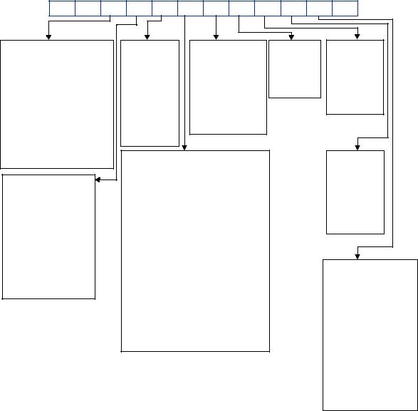
iXH and pXH Dry Pumping Systems
A |
C |
X |
|
X |
X |
X |
X |
X |
X |
X |
X |
0 |
|
Booster Size |
|
|
|
TMS System |
|
Exhaust |
|
|
Seals |
|
Pump |
||
|
|
|
|
|
|
|
|
|
|
|
|
|
Motor |
Low Voltage |
High Voltage |
|
0 |
= Standard |
|
0 = r |
|
|
0 = r |
|
0 = None |
||
0 = None |
A = None |
|
1 |
= T-Variant |
|
1 = Standard |
|
1 = r |
|
||||
|
2 |
= T-Variant |
|
without |
|
|
2 =Standard |
|
1 = 4.5 kW |
||||
1 = 600G |
B = 600G |
|
|
+ heated |
|
check valve. |
|
|
|
2 = 7.5 kW |
|||
2 = r |
C = r |
|
|
booster |
|
2 = r |
|
|
|
|
3 = 11 kW |
||
3 = 1200 |
D = 1200 |
|
3 |
= r |
|
|
3 = Standard with |
|
|
|
|
||
4 = 1800 |
E = 1800 |
|
4 |
= r |
|
|
check valve. |
|
|
|
|
||
5 = 3000 |
F = 3000 |
|
5 |
= r |
|
|
|
|
|
|
|
|
|
6 = 4500 |
G = 4500 |
|
Gas Module |
|
|
|
|
|
|
Booster |
|||
7 = 6000 |
H = 6000 |
|
|
|
|
|
|
|
|||||
|
|
|
|
|
|
|
|
|
|
Motor |
|||
|
|
|
|
0 |
= None (pXH) |
|
6 = Single Mode + |
|
|
|
|||
Dry Pump |
|
|
|
|
|
|
|
|
|||||
|
|
|
1 |
= Loadlock |
|
(44 slm flow) |
|
|
|
0 = None |
|||
|
|
|
|
|
|
|
|
||||||
Standard |
|
Harsh |
|
|
(4 slm flow) |
|
|
|
|
|
|
1 = 1.9 kW |
|
|
|
2 |
= Single Mode |
|
7 = Single Mode + |
|
|
|
2 = 4.5 kW |
||||
|
|
|
|
|
|
|
|
||||||
0 = None (pXH) |
|
A = 100 |
|
|
(44 slm flow) |
|
(96 slm flow) |
|
|
|
3 = 7.5 kW |
||
|
|
3 |
= Single Mode |
|
8 = Single Mode + |
|
|
|
4 = r |
||||
1 = 100 |
|
B = 200 |
|
|
|
|
|
||||||
|
|
|
(96 slm flow) |
|
(133 slm flow) |
|
|
|
|
||||
2 = 200 |
|
C = 300 |
|
|
|
|
|
|
|
||||
|
|
4 |
= Single Mode |
|
9 = Single Mode + |
|
|
|
|
||||
3 = 300 |
|
D = 450 |
|
|
|
|
|
|
|||||
|
|
|
(133 slm flow) |
(204 slm flow) |
|
|
|
|
|||||
4 = r |
|
E = 500 |
|
|
|
|
|
Special |
|||||
|
|
5 |
= Single Mode |
|
A = Multi Mode |
|
|
|
|||||
5 = r |
|
|
|
|
|
|
|
Features |
|||||
|
|
|
|
(204 slm flow) |
(44 slm flow) |
|
|
|
|||||
6 = r |
|
|
|
|
|
|
|
|
|||||
|
|
|
|
|
|
|
B = Multi Mode |
|
|
|
|
||
7 = r |
|
|
|
|
|
|
|
|
|
|
0 = None |
||
|
|
|
|
|
|
|
(96 slm flow) |
|
|
|
|||
|
|
|
|
|
|
|
|
|
|
|
1 = Application Specific |
||
|
|
|
|
|
|
|
|
C = Multi Mode |
|
|
|
||
|
|
|
|
|
|
|
|
|
|
|
2 = Application Specific |
||
|
|
|
|
|
|
|
|
(133 slm flow) |
|
|
|
||
|
|
|
|
|
|
|
|
|
|
|
3 = Application Specific |
||
|
|
|
|
|
|
|
|
D = Multi Mode |
|
|
|
||
|
|
|
|
|
|
|
|
|
|
|
4 = Application Specific |
||
|
|
|
|
|
|
|
|
(204 slm flow) |
|
|
|
||
|
|
|
|
|
|
|
|
|
|
|
5 = Application Specific |
||
|
|
|
|
|
|
|
|
|
|
|
|
|
|
|
|
|
|
|
|
|
|
|
|
|
|
|
6 = Application Specific |
|
|
|
|
|
|
|
|
|
|
|
|
|
7 = Application Specific |
|
|
|
|
|
|
|
|
|
|
|
|
|
8 = Application Specific |
Where r = reserved for future use |
|
|
|
|
|
|
|
|
9 = Application Specific |
||||
|
|
|
|
|
|
|
|
|
|||||
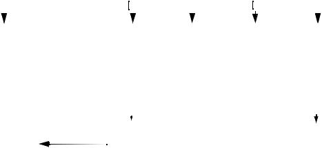
iXL Dry Pumping Systems
|
|
|
|
A |
|
S |
|
X |
|
X |
|
X |
|
X |
|
|
|
X |
|
|
X |
|
X |
|
X |
0 |
|
|
0 |
|
|
|||||||||||||||||||
|
|
|
|
|
|
|
|
|
|
|
|
|
|
|
|
|
|
|
|
|
|
|
|
|
|
|
|
|
|
|
|
|
|
|
|
|
|
|
|
|
|
|
|
|
|
|
||||
|
|
|
|
|
|
|
|
|
|
|
|
|
|
|
|
|
|
|
|
|
|
|
|
|
|
|
|
|
|
|
|
|
|
|
|
|
|
|
|
|||||||||||
|
|
|
|
|
|
|
|
|
|
|
|
|
|
|
|
|
|
|
|
|
|
|
|
|
|
|
|
|
|
|
|
|
|
|
|
|
|
|
|
|
|
|
|
|
|
|
|
|
|
|
Booster Size |
|
|
|
|
|
|
|
TMS System |
|
|
Exhaust |
|
|
|
|
Seals |
|
|
|
Pump |
|
|||||||||||||||||||||||||||||
|
|
|
|
|
|
|
|
|
|
|
|
|
|
|
|
|
|
|
|
|
|
|
|
|
|
|
|
|
|
|
|
|
|
|
|
|
|
|
|
|
|
|
|
Motor |
|
|||||
Low Voltage |
High Voltage |
|
|
|
0 = Standard |
|
|
0 = r |
|
|
|
|
|
|
|
|
|
0 = r |
|
|
|
|
|
|
|
|
|
|
|
|||||||||||||||||||||
|
|
|
|
|
|
|
|
|
|
|
1 = r |
|
|
|
|
1 = Standard |
|
|
|
1 = r |
|
|
|
|
0 = None |
|
||||||||||||||||||||||||
0 |
= None |
A = None |
|
|
|
|
|
|
|
|
|
|
|
|
|
|
|
|
|
without |
|
|
|
|
|
2 = Standard |
|
1 = 4.5 kW |
|
|||||||||||||||||||||
1 |
= r |
B = r |
|
|
|
|
|
|
|
|
|
|
|
|
|
|
|
|
|
|
|
check valve. |
|
|
|
3 = EES |
|
|
2 = 7.5 kW |
|
||||||||||||||||||||
|
|
|
|
|
|
|
|
|
|
|
|
|
|
|
|
|
|
|
|
|
||||||||||||||||||||||||||||||
2 = r |
C = r |
|
|
|
|
|
|
|
|
|
|
|
|
|
|
|
|
|
|
2 = r |
|
|
|
|
|
|
|
|
|
|
|
|
|
|
|
|
3 = 11 kW |
|
||||||||||||
|
|
|
|
|
|
|
|
|
|
|
|
|
|
|
|
|
|
|
|
|
|
|
|
|
|
|
|
|
|
|
|
|
|
|||||||||||||||||
3 |
= r |
D = r |
|
|
|
|
|
|
|
|
|
|
|
|
|
|
|
|
|
|
3 = r |
|
|
|
|
|
|
|
|
|
|
|
|
|
|
|
|
|
|
|
|
|
|
|
||||||
4 |
= 1800 |
E = 1800 |
|
|
|
|
|
|
|
|
|
|
|
|
|
|
|
|
|
|
|
|
|
|
|
|
|
|
|
|
|
|
|
|
|
|
|
|
|
|
|
|
|
|
|
|||||
5 |
= 3000 |
F = 3000 |
|
|
|
|
|
|
|
|
|
|
|
|
|
|
|
|
|
|
|
|
|
|
|
|
|
|
|
|
|
|
|
|
|
|
|
|
|
|
|
|
|
|
|
|||||
|
|
|
|
|
|
|
|
|
|
|
|
Gas Module |
|
|
|
|
|
|
|
|
|
|
|
|
|
|
|
|
|
|
|
|
|
|
Booster |
|
||||||||||||||
|
|
|
|
|
|
|
|
|
|
|
|
|
|
|
|
|
|
|
|
|
|
|
|
|
|
|
|
|
|
|
||||||||||||||||||||
|
|
|
|
|
|
|
|
|
|
|
|
0 |
= None |
|
|
|
|
|
|
|
|
|
|
|
|
|
|
|
|
|
|
|
|
|
|
|
|
Motor |
|
|||||||||||
Dry Pump |
|
|
|
|
|
|
|
|
|
|
|
|
|
|
|
|
|
|
|
|
|
|
|
|
|
|
|
|
|
|
|
|
|
|
|
|
|
|
|
|||||||||||
0 |
= None |
|
|
|
|
|
|
|
1 |
= Loadlock (4 slm flow) |
|
|
|
|
|
|
|
|
|
|
|
|
|
0 = None |
|
|||||||||||||||||||||||||
|
|
|
|
|
|
|
2 |
= r |
|
|
|
|
|
|
|
|
|
|
|
|
|
|
|
|
|
|
|
|
|
|
|
|
1 = r |
|
||||||||||||||||
1 |
= r |
|
|
|
|
|
|
|
3 |
= r |
|
|
|
|
|
|
|
|
|
|
|
|
|
|
|
|
|
|
|
|
|
|
|
|
2= 4.5 kW |
|
||||||||||||||
2 |
= r |
|
|
|
|
|
|
|
4 |
= r |
|
|
|
|
|
|
|
|
|
|
|
|
|
|
|
|
|
|
|
|
|
|
|
|
3 = 7.5 kW |
|
||||||||||||||
3 |
= 250 |
|
|
|
|
|
|
|
|
|
|
|
|
|
|
|
|
|
|
|
|
|
|
|
|
|
|
|
|
|
|
|
|
|
|
|
|
|
|
|
|
4 = r |
|
|||||||
|
|
|
|
|
|
|
|
|
|
|
|
|
|
|
|
|
|
|
|
|
|
|
|
|
|
|
|
|
|
|
|
|
|
|
|
|
|
|
|
|
||||||||||
4 |
= r |
|
|
|
|
|
|
|
|
|
|
|
|
|
|
|
|
|
|
|
|
|
|
|
|
|
|
|
|
|
|
|
|
|
|
|
|
|
|
|
|
|
||||||||
|
|
|
|
|
|
|
|
|
|
|
|
|
|
|
|
|
|
|
|
|
|
|
|
|
|
|
|
|
|
|
|
|
|
|
|
|
|
|
|
|
|
|
|
|
|
|
||||
5 |
= 500 |
|
|
|
|
|
|
|
|
|
|
|
|
|
|
|
|
|
|
|
|
|
|
|
|
|
|
|
|
|
|
|
|
|
|
|
|
|
|
|
|
|
|
|
|
|
|
|
||
|
|
|
|
|
|
|
|
|
|
|
|
|
|
|
|
|
|
|
|
|
|
|
|
|
|
|
|
|
|
|
|
|
|
|
|
|
|
|
|
|
|
|
|
|
|
|
||||
6 |
= 750 |
|
|
|
|
|
|
|
|
|
|
|
|
|
|
|
|
|
|
|
|
|
|
|
|
|
|
|
|
|
|
|
|
|
|
|
|
|
|
|
|
|
|
|
|
|
|
|
||
|
|
|
|
|
|
|
|
|
|
|
|
|
|
|
|
|
|
|
|
|
|
|
|
|
|
|
|
|
|
|
|
|
|
|
|
|
|
|
|
|
|
|
|
|
|
|
|
|
|
|
Where r = reserved for future use

Declaration of Conformity
We, Edwards Limited,
Crawley Business Quarter,
Manor Royal,
Crawley,
West Sussex RH10 9LW, UK
declare under our sole responsibility, as manufacturer and person within the EU authorised to assemble the technical file, that the product(s)
|
Low Volt Systems |
High Volt Systems |
|
(200 - 230V) |
(380 - 460V) |
iXH100 |
AC010xy21000 |
ACA10xy21000 |
iXH200H |
AC0B0xy22000 |
ACAB0xy22000 |
iXH610 |
AC110xy21100 |
ACB10xy21100 |
iXH1210 |
AC310xy21200 |
ACD10xy21200 |
iXH1210H |
AC3A0xy22200 |
ACDA0xy22200 |
iXH1210HT |
AC3A1xy22200 |
ACDA1xy22200 |
iXH1220H |
AC3B0xy22200 |
ACDB0xy22200 |
iXH1220HT |
AC3B1xy22200 |
ACDB1xy22200 |
iXH1220HTX |
AC3B2xy22200 |
ACDB2xy22200 |
iXH1820 |
AC420xy22200 |
ACE20xy22200 |
iXH1820H |
AC4B0xy22200 |
ACEB0xy22200 |
iXH1820T |
AC421xy22200 |
ACE21xy22200 |
Where x = 1, 2, 3, 4, 5, 6, 7, 8, 9, A, B, C or D depending on gas module type
Where y=1 means 'no check valve' and y=3 means 'check valve supplied'
to which this declaration relates is in conformity with the following standard(s) or other normative document(s):
EN1012-2: 1997 Compressor and Vacuum Pumps Safety Requirements; Part 2 - Vacuum Pumps. EN61010-1: 2010 Safety Requirements for Electrical Equipment for Measurement, Control and
Laboratory Use; Part 1 – General Requirements.
EN 61326-1: 2006 Electrical equipment for measurement, control and laboratory use - EMC requirements (Industrial Location Immunity – Class A Emissions)
EN50581:2012 Technical Documentation for the Assessment of Electrical and Electronic Products with respect to the Restriction of Hazardous Substances
ANSI/UL 61010-1 and CAN/CSA-C22.2 No. 61010-1, 2nd Edition July 12, 2004, including revision July 22, 2005 - Safety Requirements for Electrical Equipment for Measurement, Control and Laboratory Use, Part 1: General Requirements
SEMI S2-0709 - Environmental, Health, and Safety Guideline for Semiconductor Manufacturing Equipment
when installed in accordance with the instruction manual supplied with the pump, following the provisions of:
2006/95/EC |
Low Voltage Directive. |
2004/108/EC |
Electromagnetic Compatibility Directive. |
2006/42/EC |
Machinery Safety Directive. |
2011/65/EU* |
Restriction of Certain Hazardous Substances (RoHS) Directive |
* i.e. The product(s) contain less than - 0.1wt% for hexavalent chromium, lead, mercury, PBB and PBDE; 0.01wt% for cadmium - in homogeneous materials (subject to the exemptions allowed by the Directive). The RoHS Directive does not legally apply to industrial vacuum equipment until July 2019 (July 2017 for instruments).
Note: This declaration covers all product serial numbers from the date this Declaration was signed onwards.
22.10.2013, Burgess Hill
Mr Mark Hope, Global Technical Support Manager |
Date and Place |
This product has been manufactured under a quality system certified to ISO9001:2008
P200-02-320 Issue J

Declaration of Conformity
We, |
Edwards Limited, |
|
Crawley Business Quarter |
|
Manor Royal, |
|
Crawley, |
|
West Sussex RH10 9LW, UK |
declare under our sole responsibility, as manufacturer and person within the EU authorised to assemble the technical file, that the product(s)
|
Low Volt Systems |
High Volt Systems |
|
(200-230V) |
(380-460V) |
iXH3030 |
AC530xy22300 |
ACF30xy22300 |
iXH3030T |
AC531xy22300 |
ACF31xy22300 |
iXH3030TX |
AC532xy22300 |
ACF32xy22300 |
iXH3045H |
AC5D0xy23310 |
ACFD0xy23310 |
iXH4545HT |
AC6D1xy23300 |
ACGD1xy23300 |
iXH4545HT |
- |
ACGD1B123390 |
iXH6045H |
AC7D0xy23300 |
ACHD0xy23300 |
iXH6045H |
AC7D02123310 |
ACHD02123310 |
iXH6045HT |
AC7D1xy23300 |
ACHD1xy23300 |
iXH450H |
AC0D0xy23000 |
ACAD0xy23000 |
pXH4500 |
AC6000120300 |
ACG000120300 |
pXH4500 |
- |
ACG000120310 |
pXH6000 |
AC7000120300 |
ACH000120300 |
iXL500Q |
AS450zy23300 |
ASE50zy23300 |
iXL500R |
AS550zy23300 |
ASF50zy23300 |
Where x = 1, 2, 3, 4, 5, 6, 7, 8, 9, A, B, C or D depending on gas module type
Where y = 1 means 'no check valve' and y=3 means 'check valve supplied'
Where z = 1, 2, 3, 5, A or B depending on gas module type for iXL
to which this declaration relates is in conformity with the following standard(s) or other normative document(s)
EN1012-2: 1997 |
Compressor and Vacuum Pumps Safety Requirements. Part 2 - Vacuum Pumps |
EN61010-1: 2010 |
Safety Requirements for Electrical Equipment for Measurement, Control and Laboratory |
|
Use. Part 1 – General Requirements. |
EN 61326-1: 2006 |
Electrical equipment for measurement, control and laboratory use - EMC requirements |
|
(Industrial Location Immunity – Class A Emissions) |
EN50581:2012 |
Technical Documentation for the Assessment of Electrical and Electronic Products |
|
with respect to the Restriction of Hazardous Substances |
ANSI/UL 61010-1 and CAN/CSA-C22.2 No. 61010-1, 2nd Edition July 12, 2004, including revision July 22, 2005 - Safety Requirements for Electrical Equipment for Measurement, Control and Laboratory Use, Part 1: General Requirements
SEMI S2-0709 - Environmental, Health, and Safety Guideline for Semiconductor Manufacturing Equipment
when installed in accordance with the instruction manual supplied with the pump, following the provisions of:
2006/95/EC |
Low Voltage Directive |
2004/108/EC |
Electromagnetic Compatibility Directive |
2006/42/EC |
Machinery Safety Directive |
2011/65/EU* |
Restriction of Certain Hazardous Substances (RoHS) Directive |
* i.e. The product(s) contain less than - 0.1wt% for hexavalent chromium, lead, mercury, PBB and PBDE; 0.01wt% for cadmium - in homogeneous materials (subject to the exemptions allowed by the Directive). The RoHS Directive does not legally apply to industrial vacuum equipment until July 2019 (July 2017 for instruments).
Note: This declaration covers all product serial numbers from the date this Declaration was signed onwards.
22.10.2013, Burgess Hill
Mr Mark Hope, Global Technical Support Manager |
Date and Place |
This product has been manufactured under a quality system certified to ISO9001:2008
P200-02-720 Issue K

Declaration of Conformity
We, |
Edwards Limited, |
|
Crawley Business Quarter, |
|
Manor Royal, |
|
Crawley, |
|
West Sussex, RH10 9LW, UK |
declare under our sole responsibility, as manufacturer and person within the EU authorised to assemble the technical file, that the product(s)
|
Low Volt Systems |
High Volt Systems |
|
(200-230V) |
(380-460V) |
iXH500H |
AC0E0xy23000 |
ACAE0xy23000 |
iXH3050H |
AC5E0xy23310 |
ACFE0xy23310 |
iXH3050HTX |
AC5E2xy23300 |
ACFE2xy23300 |
iXH4550HT |
AC6E1xy23300 |
ACGE1xy23300 |
iXH6050H |
AC7E0xy23300 |
ACHE0xy23300 |
iXH6050HT |
AC7E1xy23300 |
ACHE1xy23300 |
Where x = 1, 2, 3, 4, 5, 6, 7, 8, 9, A, B, C or D depending on gas module type
Where y = 1 means ‘no check valve’ and y = 3 means ‘check valve supplied’
to which this declaration relates is in conformity with the following standard(s) or other normative document(s)
EN1012-2:1996, A1: 2009 |
Compressors and Vacuum Pumps. Safety Requirements. |
|
|
Part 2 - Vacuum Pumps. |
|
EN61010-1: 2010 |
Safety Requirements for Electrical Equipment for Measurement, |
|
|
Control and Laboratory Use. Part 1 - General Requirements. |
|
EN 61326-1: 2006 |
Electrical equipment for measurement, control and laboratory |
|
|
Use - EMC requirements. (Industrial Location Immunity |
|
|
- |
Class A Emissions) |
EN50581:2012 |
Technical Documentation for the Assessment of Electrical and Electronic Products |
|
|
with respect to the Restriction of Hazardous Substances |
|
ANSI/UL 61010-1 and CAN/CSA-C22.2 No. 61010-1, 2nd Edition July 12, 2004, including revision July 22, 2005 – Safety Requirements for Electrical Equipment for Measurement, Control and Laboratory Use - Part 1: General Requirements
and fulfils all the relevant provisions of
2006/42/EC |
Machinery Directive |
2006/95/EC |
Low Voltage Directive |
2004/108/EC |
Electromagnetic Compatibility (EMC) Directive |
2011/65/EU* |
Restriction of Certain Hazardous Substances (RoHS) Directive |
* i.e. The product(s) contain less than - 0.1wt% for hexavalent chromium, lead, mercury, PBB and PBDE; 0.01wt% for cadmium - in homogeneous materials (subject to the exemptions allowed by the Directive). The RoHS Directive does not legally apply to industrial vacuum equipment until July 2019 (July 2017 for instruments).
Note: This declaration covers all product serial numbers from the date this Declaration was signed onwards.
22.10.2013, Burgess Hill
Mr Mark Hope, Global Technical Support Manager |
Date and Place |
This product has been manufactured under a quality system certified to ISO9001:2008
P200-06-000 Issue C

Declaration of Conformity
We, |
Edwards Limited, |
|
|
|
Crawley Business Quarter, |
|
|
|
Manor Royal, |
|
|
|
Crawley, |
|
|
|
West Sussex |
RH10 9LW, UK |
|
declare under our sole responsibility, as manufacturer and person within the EU authorised to assemble the |
|||
technical file, that the product(s) |
|
||
|
|
Low Volt Systems |
High Volt Systems |
|
|
(200-230V) |
(380-460V) |
|
iXL250Q |
AS43001x2300 |
ASE3001x2300 |
|
iXL750Q |
AS46001x4300 |
ASE6001x4300 |
|
iXL750R |
AS56001x4300 |
ASF6001x4300 |
Where x = 2 means 'standard booster oilbox evacuation' and x=3 means 'external booster oilbox evacuation'
to which this declaration relates is in conformity with the following standard(s) or other normative document(s)
EN1012-2: 1997 |
Compressor and Vacuum Pumps Safety Requirements. Part 2 - Vacuum Pumps |
EN61010-1: 2010 |
Safety Requirements for Electrical Equipment for Measurement, Control and Laboratory |
|
Use. Part 1 – General Requirements. |
EN 61326-1: 2006 |
Electrical equipment for measurement, control and laboratory use - EMC requirements |
|
(Industrial Location Immunity – Class A Emissions) |
ANSI/UL 61010-1 and CAN/CSA-C22.2 No. 61010-1, 2nd Edition July 12, 2004, including revision July 22, 2005 - Safety Requirements for Electrical Equipment for Measurement, Control and Laboratory Use, Part 1: General Requirements
when installed in accordance with the instruction manual supplied with the pump, following the provisions of:
2006/95/EC |
Low Voltage Directive |
2004/108/EC |
Electromagnetic Compatibility Directive |
2006/42/EC |
Machinery Safety Directive |
Note: This declaration covers all product serial numbers from the date this Declaration was signed onwards.
|
|
22.10.2013, Burgess Hill |
Mr Mark Hope, Global Technical Support Manager |
|
Date and Place |
This product has been manufactured under a quality system certified to ISO9001:2008
P200-06-620 Issue B

P601-01-100
Issue C Original
The Chinese regulatory requirement on the Control of Pollution Caused by Electronic Information Products No. 39 (also known as ‘China RoHS’) mandates that manufacturers of certain categories of electronic products sold in China after 1st March 2007 –
Mark the product and packaging
Define the Product’s Environment Protection Use Period (EPUP)
Provide a Materials Content Declaration.
|
|
|
|
Product Labels |
|
|
|
|
|
|
|
Product |
Product Label |
|
Meaning |
||
|
|
|
|
|
|
All iXH, iXL500 and |
|
|
|
|
Indicates toxic or hazardous substance contained in at least |
pXH models |
|
|
|
|
|
|
|
|
|
|
|
|
20 |
|
|
one of the homogeneous materials used for this part is |
|
|
|
|
|
||
|
|
|
|
above the limit requirement in SJ/T11363-2006. |
|
|
|
|
|
|
Environmental Protection Use Period is 20 years. |
|
|
|
|
|
|
Packaging information
Pallet |
Overshipper |
Protection Pieces |
Support Braces |
|
|
|
|
NW |
|
|
|
|
|
|
|
Recyclable Natural Wood |
Recyclable Cardboard |
Recyclable Polypropylene |
Recyclable Mild Steel |
|
|
|
|
Environment Protection Use Period (EPUP)
This is the period in years during which the toxic or hazardous substances or elements contained in this product will not leak or mutate under normal operating conditions so that the use of such electronic information products will not result in any severe environmental pollution, any bodily injury or damage to any assets.
The Environmental Protection Use Period is 20 years for this product.
For the purposes of EPUP, normal operating conditions are considered to be use in accordance with the product’s instruction manual.
Materials Content Declaration for all iXH, iXL & pXH models
|
|
|
Toxic or Hazardous Substances and Elements |
|
|||
Part name |
|
|
|
|
|
|
|
Lead (Pb) |
Mercury (Hg) |
Cadmium (Cd) |
Hexavalent |
Poly brominated |
Poly brominated |
||
|
|||||||
|
Chromium (Cr (VI)) |
biphenyls (PBB) |
diphenyl ethers (PBDE) |
||||
|
|
|
|
||||
|
|
|
|
|
|
|
|
Motor (Mechanical |
O |
O |
O |
O |
O |
O |
|
Booster) |
|||||||
|
|
|
|
|
|
||
|
|
|
|
|
|
|
|
Motor (pump) |
O |
O |
O |
O |
O |
O |
|
|
|
|
|
|
|
|
|
Pump & Booster |
O |
O |
O |
O |
O |
O |
|
|
|
|
|
|
|
|
|
Electronics and Controls |
O |
O |
X |
O |
O |
O |
|
|
|
|
|
|
|
|
|
Cooling System |
O |
O |
O |
O |
O |
O |
|
|
|
|
|
|
|
|
|
Purge System |
O |
O |
O |
O |
O |
O |
|
|
|
|
|
|
|
|
|
O: Indicates that this toxic or hazardous substance contained in all of the homogeneous materials for this part is below the limit requirement in SJ/T11363-2006.
X: Indicates that this toxic or hazardous substance contained in at least one of the homogeneous materials used for this part is above the limit requirement in SJ/T11363-2006.
DJD 24/03/10

|
|
|
|
M561-00-880 Issue C |
|
|
|
|
|
||
|
|
Contents |
|
||
|
|
Section |
Page |
||
|
1 |
Introduction ....................................................................................... |
1 |
||
|
1.1 |
Scope and definitions ................................................................................................... |
1 |
||
|
1.2 |
Applications ............................................................................................................... |
2 |
||
|
1.3 |
Description ................................................................................................................ |
2 |
||
|
1.4 |
Priority of control ........................................................................................................ |
2 |
||
|
1.5 |
Active utility control .................................................................................................... |
3 |
||
|
2 |
Technical data .................................................................................... |
5 |
||
|
2.1 |
General technical data .................................................................................................. |
5 |
||
|
2.2 |
Performance data ........................................................................................................ |
7 |
||
|
2.3 |
Loading data .............................................................................................................. |
8 |
||
|
2.4 |
Nitrogen purge data ..................................................................................................... |
9 |
||
|
2.5 |
Electrical data ........................................................................................................... |
11 |
||
|
2.6 |
Cooling-water data ..................................................................................................... |
17 |
||
|
2.7 |
T variants ................................................................................................................ |
20 |
||
|
2.8 |
Tracer gas analysis ..................................................................................................... |
20 |
||
|
3 |
Installation ....................................................................................... |
23 |
||
|
3.1 |
Locate the dry pumping system ...................................................................................... |
24 |
||
|
3.2 |
Lubrication ............................................................................................................... |
25 |
||
|
3.3 |
Connect the dry pumping system to your vacuum/exhaust system ............................................. |
25 |
||
|
3.4 |
Connect to your factory extraction system (optional) ............................................................ |
27 |
||
|
3.5 |
Connect the nitrogen supply .......................................................................................... |
28 |
||
|
3.5.1 |
Flammable/pyrophoric materials .................................................................................... |
28 |
||
|
3.5.2 |
Gas purges ............................................................................................................... |
29 |
||
|
3.6 |
Leak-test the system ................................................................................................... |
29 |
||
|
3.7 |
Electrical supply ........................................................................................................ |
29 |
||
|
3.7.1 |
Mains supply cable connection ....................................................................................... |
31 |
||
|
3.8 |
Connect an additional RF earth (ground) (optional) .............................................................. |
35 |
||
|
3.9 |
Connect to your emergency stop circuit ............................................................................ |
35 |
||
|
3.10 |
Connect and set up the cooling-water .............................................................................. |
36 |
||
|
3.11 |
Accessories ............................................................................................................... |
37 |
||
|
3.12 |
Commission the system ................................................................................................ |
37 |
||
|
3.13 |
Install additional safety equipment .................................................................................. |
38 |
||
|
4 |
Operation ........................................................................................ |
39 |
||
|
4.1 |
Start-up .................................................................................................................. |
39 |
||
|
4.1.1 |
MicroTIM operation ..................................................................................................... |
40 |
||
|
4.1.2 |
PDT operation ........................................................................................................... |
40 |
||
|
4.1.3 |
Front panel control operation ........................................................................................ |
40 |
||
|
4.2 |
Status indicators ........................................................................................................ |
40 |
||
|
4.3 |
Manual shut-down ...................................................................................................... |
41 |
||
|
4.3.1 |
Shut-down modes ....................................................................................................... |
41 |
||
|
4.3.2 |
MicroTIM operation ..................................................................................................... |
41 |
||
|
4.3.3 |
PDT operation ........................................................................................................... |
41 |
||
|
4.3.4 |
Front panel control operation ........................................................................................ |
41 |
||
|
4.4 |
Automatic shut-down .................................................................................................. |
42 |
||
gea/0179/01/12 |
4.5 |
Unplanned shut-down and alarms .................................................................................... |
43 |
||
4.6 |
Emergency stop |
44 |
|||
|
|||||
|
4.7 |
Restart the pump after an emergency stop or automatic shut-down .......................................... |
44 |
||
|
4.8 |
Advanced control and monitoring .................................................................................... |
44 |
||
|
|
|
|
||
|
|
© Edwards Limited 2012. All rights reserved. |
Page i |
||
|
|
Edwards and the Edwards logo are trademarks of Edwards Limited. |
|
||
Contents

M561-00-880 Issue C
Contents
5
5.1
5.2
5.3
5.4
5.5
5.6
5.6.1
5.6.2
5.6.3
5.7
Maintenance ..................................................................................... |
45 |
Safety and maintenance frequency .................................................................................. |
45 |
Relocate the system for maintenance ............................................................................... |
46 |
Draining the cooling water ............................................................................................ |
47 |
General maintenance .................................................................................................. |
48 |
Inspect the connections, pipelines, cables and fittings .......................................................... |
48 |
Gas module configuration ............................................................................................. |
49 |
iXH single mode and single mode+ ................................................................................... |
49 |
Multi mode ............................................................................................................... |
49 |
iXL variants .............................................................................................................. |
50 |
System operating temperature configuration ...................................................................... |
50 |
6 |
Transportation, storage and disposal ........................................................ |
51 |
6.1 |
Transportation .......................................................................................................... |
51 |
6.2 |
Storage ................................................................................................................... |
51 |
6.3 |
Disposal ................................................................................................................... |
51 |
7 |
Service, spares and accessories .............................................................. |
53 |
7.1 |
Introduction ............................................................................................................. |
53 |
7.2 |
Service .................................................................................................................... |
53 |
7.3 |
Ordering accessories ................................................................................................... |
54 |
Appendix A1 Pump display terminal .................................................................. |
57 |
|
A1.1 |
LEDs ....................................................................................................................... |
57 |
A1.2 |
Pump start / stop and control ........................................................................................ |
57 |
A1.3 |
Warning / Alarm display and acknowledgement ................................................................... |
58 |
A1.4 |
Menus ..................................................................................................................... |
58 |
A1.4.1 |
Normal menu ............................................................................................................ |
58 |
A1.4.2 |
Status menu ............................................................................................................. |
59 |
A1.4.3 |
SETUP menu ............................................................................................................. |
60 |
A1.4.4 |
COMMANDS menu ....................................................................................................... |
61 |
A1.4.5 |
INV FAULT HIST (Display Inverter Fault History) menu ........................................................... |
61 |
A1.4.6 |
SOFTWARE VERSION Display menu ................................................................................... |
62 |
A1.4.7 |
FIT ACCESSORY menu .................................................................................................. |
62 |
A1.4.8 |
IP Configuration menu ................................................................................................. |
62 |
A1.4.9 |
Display attributes menu ............................................................................................... |
63 |
Appendix A2 Troubleshooting .......................................................................... |
65 |
|
A2.1 |
Warnings ................................................................................................................. |
65 |
A2.1.1 |
LED warning indicators ................................................................................................. |
65 |
A2.1.2 |
PDT warnings ............................................................................................................ |
65 |
A2.2 |
Alarms .................................................................................................................... |
68 |
A2.2.1 |
LED alarm indicators ................................................................................................... |
68 |
A2.2.2 |
PDT alarms ............................................................................................................... |
68 |
A2.3 |
Inverter warnings and alarms ......................................................................................... |
70 |
A2.4 |
Other problems ......................................................................................................... |
75 |
A2.4.1 |
Pump controller communications .................................................................................... |
75 |
|
For return of equipment, complete the HS Forms at the end of this manual. |
|
Page ii |
© Edwards Limited 2012. All rights reserved. |
|
Edwards and the Edwards logo are trademarks of Edwards Limited. |
|
|
M561-00-880 Issue C |
Illustrations |
|
|
Figure |
|
Page |
1 |
Applications ............................................................................................................... |
2 |
2 |
The front panel controls ................................................................................................ |
3 |
3 |
Front view of pumping system ......................................................................................... |
3 |
4 |
The controls/connectors on the rear of the pump ................................................................. |
4 |
5 |
Centre of gravity and levelling foot loads ........................................................................... |
9 |
6 |
Reduce the effective system footprint .............................................................................. |
25 |
7 |
Connecting the pump inlet ............................................................................................ |
27 |
8 |
The Harting Han® K 4/4 cable-mounted connector ............................................................... |
32 |
9 |
The Harting 100A axial screw module cable-mounted connector ............................................... |
33 |
10 |
Customer connection kit - combination low volts iXL750 ........................................................ |
34 |
11 |
Electrical connector locking mechanism ............................................................................ |
35 |
A1 |
Pump display terminal ................................................................................................. |
57 |
Tables |
|
|
Table |
|
Page |
1 |
General technical data .................................................................................................. |
5 |
2 |
General technical data .................................................................................................. |
6 |
3 |
Performance data ........................................................................................................ |
7 |
4 |
Loading data (refer to Figure 5) ....................................................................................... |
8 |
5 |
Nitrogen purge data for iXH and iXL systems ........................................................................ |
9 |
6 |
Gas module types and flows .......................................................................................... |
10 |
7 |
Electrical data iXH100 to iXH1820/H/T ............................................................................. |
11 |
8 |
General electrical data ................................................................................................ |
14 |
9 |
Electrical connections .................................................................................................. |
15 |
10 |
Wire assembly according to VDE 0295 ............................................................................... |
16 |
11 |
Water cooling system data ............................................................................................ |
17 |
12 |
Cooling water supply temperature ................................................................................... |
18 |
13 |
Water consumption data ............................................................................................... |
19 |
14 |
Heater data .............................................................................................................. |
20 |
15 |
Tracer gas test parameters ........................................................................................... |
20 |
16 |
Tracer gas test system parameters .................................................................................. |
20 |
17 |
Worst case test results ................................................................................................. |
21 |
18 |
Extraction rates required by system variant ....................................................................... |
22 |
19 |
Alarm actions ............................................................................................................ |
42 |
20 |
Pump protection sensors .............................................................................................. |
43 |
21 |
Dry pump and booster temperature settings ....................................................................... |
50 |
22 |
Accessories ............................................................................................................... |
54 |
23 |
Seismic bracket kits .................................................................................................... |
55 |
24 |
Exhaust check valve kits ............................................................................................... |
55 |
A1 |
Pump start control ...................................................................................................... |
57 |
A2 |
Pump stop and control ................................................................................................. |
58 |
A3 |
Normal menu ............................................................................................................ |
58 |
A4 |
Normal menu ............................................................................................................ |
59 |
A5 |
Status menu ............................................................................................................. |
59 |
A6 |
SETUP menu ............................................................................................................. |
60 |
A7 |
COMMANDS menu ....................................................................................................... |
61 |
A8 |
GAS VALVES menu ...................................................................................................... |
61 |
A9 |
INV FAULT HIST (Display Inverter Fault History) menu ........................................................... |
61 |
A10 |
FIT ACCESSORY menu .................................................................................................. |
62 |
Contents
© Edwards Limited 2012. All rights reserved. |
Page iii |
Edwards and the Edwards logo are trademarks of Edwards Limited. |
|

M561-00-880 Issue C
Contents
A11
A12
A13
A14
A15
A16
A17
A18
A19
A20
IP Configuration menu ................................................................................................. |
62 |
Display attributes menu ............................................................................................... |
63 |
SELECT LINE (Normal display selection menu) ..................................................................... |
63 |
UNITS (Units to display) ................................................................................................ |
63 |
Warnings ................................................................................................................. |
65 |
Alarms .................................................................................................................... |
68 |
Hexadecimal to digital conversion ................................................................................... |
70 |
Inverter alarm codes ................................................................................................... |
71 |
Inverter warnings codes ............................................................................................... |
72 |
Inverter diagnostic display text ...................................................................................... |
73 |
Associated publications
Publication title |
Publication number |
Vacuum Pump and Vacuum System Safety |
P400-40-100 |
Semiconductor Pumping Application Guide |
P411-00-090 |
Trademark Credits
Han® is a registered trademark of Harting Electric GmbH
EtherCon® is a registered trademark of Neutrik® AG
Fomblin® is a registered trademark of Solvay Solexis SpA
Page iv |
© Edwards Limited 2012. All rights reserved. |
|
Edwards and the Edwards logo are trademarks of Edwards Limited. |
M561-00-880 Issue C
1 Introduction
1.1Scope and definitions
This manual provides installation, operation and maintenance instructions for the Edwards iXH, iXL and pXH dry pumping systems. You must use your pumping system as specified in this manual otherwise the protection provided by the equipment may be impaired.
Read this manual before you install and operate your pump. Important safety information is highlighted as WARNING and CAUTION instructions; you must obey these instructions. The use of WARNINGS and CAUTIONS is defined below.
WARNING
Warnings are given where failure to observe the instruction could result in injury or death to people.
CAUTION
Cautions are given where failure to observe the instruction could result in damage to the equipment, associated equipment and/or process.
The units throughout this manual conform to the SI international system of units of measurement.
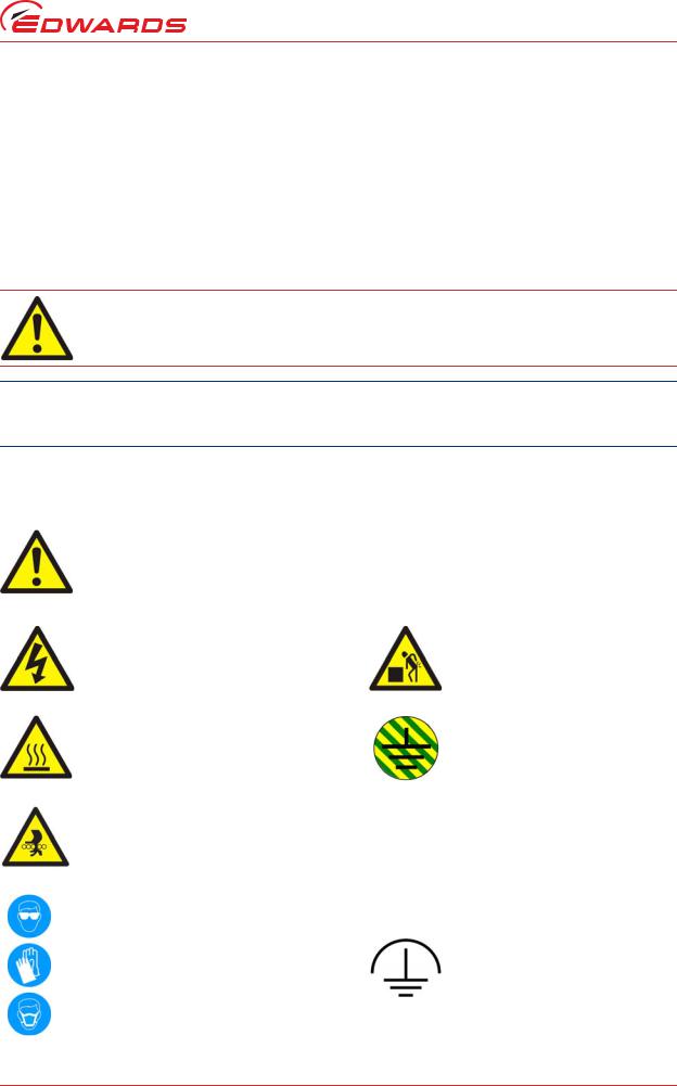
The following warning labels are on the pump:
Warning - Refer to accompanying documentation.  Warning - Maximum angle between paired slings
Warning - Risk of electric shock. |
Warning - Heavy object. |
Warning - Hot surfaces. |
Protective earth (ground). |
Warning - Moving parts present.
Warning - use protective equipment. |
RF earth (ground). |
Introduction
© Edwards Limited 2012. All rights reserved. |
Page 1 |
Edwards and the Edwards logo are trademarks of Edwards Limited. |
|

M561-00-880 Issue C
Introduction
The following warnings only appear in this manual:
Warning - Risk of explosion. |
Warning - pressurised. |
Material Safety Data Sheets for chemicals supplied by Edwards can be obtained by contacting Edwards, or on www.edwardsvacuum.com.
1.2Applications
iXH, iXL and pXH pumping systems are intended for use on the Semiconductor, Solar and FPD processes shown in Figure 1.
Figure 1 - Applications
iXH, iXL and pXH applications
ALD |
Metal Etch |
RTP |
HDP-CVD |
Metrology |
SACVD |
Implant Source |
Oxide etch |
Silicon Etch |
Lithography |
PECVD |
Strip/Ashing |
Load lock |
PVD Pre-Clean |
Transfer |
LPCVD |
PVD Process |
|
MOCVD |
RTA |
|
|
|
|
The iXL systems are intended for use on clean duty applications.
If you use the system on an application for which it is not suitable, you may invalidate your warranties. If in doubt, contact Edwards who will advise you as to the suitability of the system for any particular application.
1.3Description
The iXH dry pump range has been developed to meet the demanding requirements for process pumping solutions in the Semiconductor, Flat Panel and Solar industries. The range sets new standards for harsh process capability, reliability and reduced cost of ownership in low footprint packages.
The iXL pump range has been developed to meet cyclic loadlock duty applications used in the flat panel and solar industries.
The pXH booster systems are not intended for use as stand-alone units. Each system must be backed using a suitable Edwards dry pump selected to match process and performance specifications.
1.4Priority of control
The pumping system can be controlled by a number of modules: the front control panel (refer to Figure 2), a Pump Display Terminal (PDT), the Edwards System Controller or by the tool through the MicroTIM or one of the serial interfaces. Only one of these can have control of the system at any one time. That is, once one of these has control of the system, control requests from the others are denied.
In addition to the control modules listed above, the pXH proximity booster can control or be controlled by the Edwards backing pump. Contact Edwards for more information on how to control a pXH using an iXH or other Edwards pumping system.
The PDT indicates who is in control. LEDs are also provided on the rear panel, front panel or PDT, which illuminate to indicate 'in control'.
Page 2 |
© Edwards Limited 2012. All rights reserved. |
|
Edwards and the Edwards logo are trademarks of Edwards Limited. |
M561-00-880 Issue C
1.5Active utility control
The Active Utility Control (Green Mode) function reduces utility consumption of the system while on stand-by. The Green Mode functionality is controlled by the on/off process signal from the Tool Interface Module. Contact Edwards for advice on application and activation.
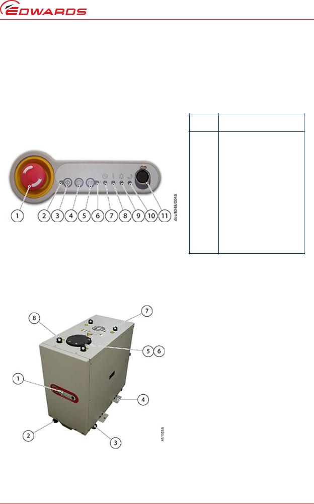
Figure 2 - The front panel controls
Item Control/connector
identification
1 EMS button
2 Running LED (green)
3 Start button
4 Stop button
5 Local control button
6 Local control LED (green)
7 Power LED (green)
8 Warning LED (amber)
9 Alarm LED (red)
10 Green Mode LED (green)
11 PDT (Pump Display Terminal) connection
Figure 3 - Front view of pumping system
Introduction
Item |
Control/connector |
|
identification |
||
|
||
|
|
|
1 |
Front panel control |
|
2 |
Levelling feet (4 off) |
|
3 |
Castors (4 off) |
|
4 |
Seismic bracket (4 off if |
|
|
fitted) |
|
5 |
Pumped gas inlet connection |
|
6 |
RF Earth (ground) cable |
|
7 |
Extraction port |
|
8 |
Lifting eyebolts (4 off) |
|
|
|
Note: iXH 100, iXH 200H and iXH 610 variants have only two eyebolts provided for lifting.
© Edwards Limited 2012. All rights reserved. |
Page 3 |
Edwards and the Edwards logo are trademarks of Edwards Limited. |
|
M561-00-880 Issue C
Introduction
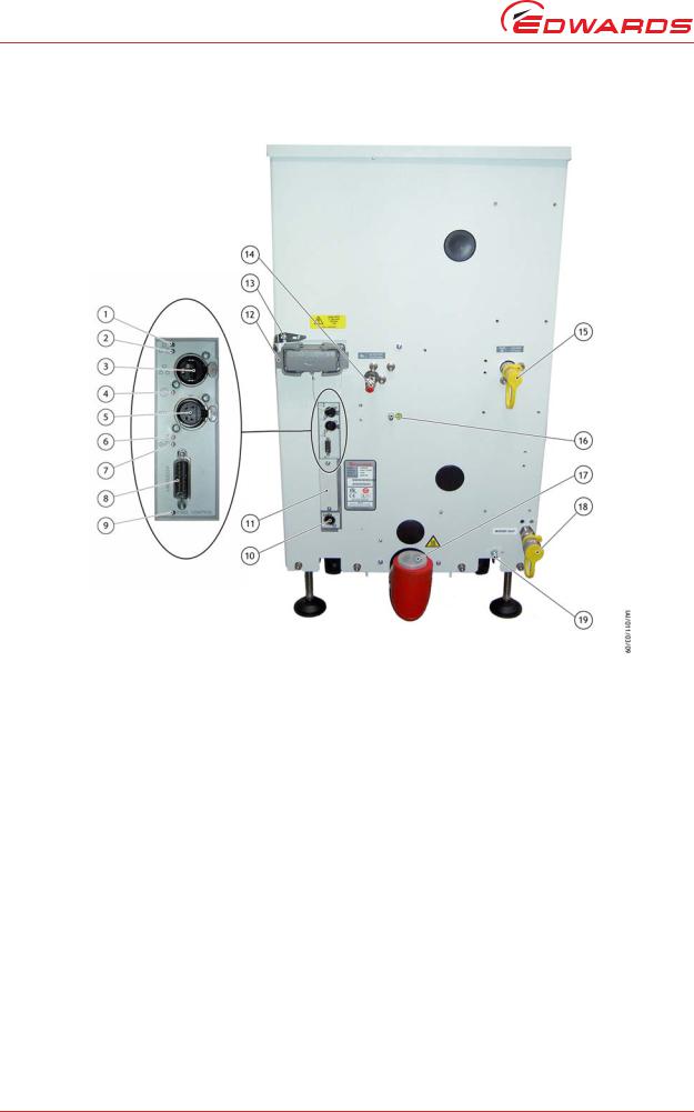
Figure 4 - The controls/connectors on the rear of the pump
Item |
Control/connector identification |
|
|
1 |
Ethernet LAN LED (green) |
2 |
Ethernet link LED (yellow) |
3 |
Ethernet connection |
4 |
Power LED (green) |
5 |
System interface |
6 |
Warning LED (yellow) |
7 |
Running and Alarm LEDs (2 colours, |
|
either green or red) |
8 |
Accessory interface |
9 |
MicroTIM in control LED (green) |
10 |
EMS interface |
|
|
Item |
Control/connector identification |
|
|
11 |
Micro TIM connection (if fitted) |
12 |
Electrical supply connection |
13 |
Electrical connector locking |
|
mechanism |
14 |
Nitrogen purge connection |
15 |
Cooling water supply connection |
16 |
Protective earth (ground) stud |
17 |
Exhaust gas outlet connection |
18 |
Cooling water return connection |
19 |
RF earth (ground) stud |
|
|
Page 4 |
© Edwards Limited 2012. All rights reserved. |
|
Edwards and the Edwards logo are trademarks of Edwards Limited. |

Edwards the and Edwards |
.2012 Limited Edwards © |
are logo |
rights All |
trademarks |
.reserved |
.Limited Edwards of |
|
5 Page
2 Technical data
2.1General technical data
Table 1 - General technical data
|
|
|
|
Characteristics |
|
|
|
|
||
|
|
|
|
|
|
|
|
|
|
|
|
Body dimensions |
|
|
|
|
|
|
|
|
|
Pump |
Length x Width x |
Mass |
Noise level |
Typical |
Initial force |
Sustained |
Pump inlet |
Exhaust gas |
Extraction |
|
Height |
(excluding |
vibration |
to push the |
force to push |
flange |
port |
||||
|
(at ultimate) |
outlet |
||||||||
|
(excludes exhaust |
packaging) |
level at inlet |
pump† |
the pump† |
(bolted) |
diameter |
|||
|
enclosure)* |
|
|
|
|
|
|
|
|
|
Units |
mm |
kg |
dB(A) |
mm/s |
kg force |
kg force |
|
|
mm |
|
|
|
|
|
|
|
|
|
|
|
|
iXH100 |
784 x 390 x 526 |
260 |
< 70 |
< 1.5 |
< 20 |
< 4 |
ISO63 |
NW40 |
105 |
|
iXH200H |
901 x 390 x 526 |
287 |
< 70 |
< 1.5 |
< 20 |
< 4 |
ISO63 |
NW40 |
105 |
|
iXH450H |
1000 x 517 x 650 |
455 |
< 70 |
< 1.5 |
< 20 |
< 10 |
ISO63 |
NW40 |
105 |
|
iXH500H |
1000 x 517 x 650 |
490 |
< 70 |
< 1.5 |
< 20 |
< 10 |
ISO63 |
NW40 |
105 |
|
iXH610 |
784 x 390 x 780 |
355 |
< 70 |
< 1.5 |
< 20 |
< 4 |
ISO100 |
NW40 |
105 |
|
iXH1210/H |
784 x 390 x 780 |
413 - 430 |
< 70 |
< 1.5 |
< 20 |
< 4 |
ISO100 |
NW40 |
105 |
|
iXH1220H/T |
901 x 390 x 780 |
455 - 460 |
< 70 |
< 1.5 |
< 20 |
< 4 |
ISO100 |
NW40 |
105 |
|
iXH1820/H/T |
901 x 390 x 780 |
471 - 487 |
< 70 |
< 1.5 |
< 20 |
< 4 |
ISO160 |
NW40 |
105 |
|
iXH3030/T |
915 x 517 x 966 |
619 - 624 |
< 70 |
< 1.5 |
< 20 |
< 10 |
ISO160 |
NW40 |
105 |
|
iXH3045H |
1000 x 517 x 966 |
776 |
70 |
< 1.5 |
< 20 |
< 10 |
ISO160 |
NW40 |
105 |
|
iXH3050H |
1000 x 517 x 966 |
811 |
70 |
< 1.5 |
< 20 |
< 10 |
ISO160 |
NW40 |
105 |
|
iXH4545HT |
1000 x 517 x 966 |
814 |
70 |
< 1.5 |
< 20 |
< 10 |
ISO200 |
NW40 |
105 |
|
iXH4550HT |
1000 x 517 x 966 |
849 |
70 |
< 1.5 |
< 20 |
< 10 |
ISO200 |
NW40 |
105 |
|
iXH6045H/T |
1080 x 517 x 966 |
860 - 865 |
74 |
< 1.5 |
< 20 |
< 10 |
ISO250 |
NW40 |
105 |
|
iXH6050H/T |
1080 x 517 x 966 |
899 |
70 |
< 1.5 |
< 20 |
< 10 |
ISO250 |
NW40 |
105 |
|
pXH4500 |
1086 x 517 x 531 |
400 |
< 70 |
< 1.5 |
< 20 |
< 10 |
ISO200 |
ISO160 |
- |
|
pXH6000 |
1086 x 517 x 531 |
435 |
< 70 |
< 1.5 |
< 20 |
< 10 |
ISO250 |
ISO160 |
- |
|
iXL250Q |
1092 x 390 x 830 |
515 |
<64 |
<1.5 |
<20 |
<10 |
ISO160 |
NW40 |
105 |
|
iXL500Q |
1186 x 517 x 966 |
860 |
< 70 |
< 1.5 |
< 20 |
< 10 |
ISO160 |
NW50 |
105 |
|
iXL500R |
1186 x 517 x 966 |
874 |
< 70 |
< 1.5 |
< 20 |
< 10 |
ISO160 |
NW50 |
105 |
|
|
|
|
|
|
|
|
|
|
|
|
C Issue 880-00-M561
Technicaldata

6 Page
.reserved rights All .2012 Limited Edwards © .Limited Edwards of trademarks are logo Edwards the and Edwards
|
|
|
Table 1 - General technical data (continued) |
|
Technicaldata |
||||||
|
|
|
|
|
|
|
|
||||
|
|
|
|
|
|
|
|
|
|
|
|
|
|
|
|
Characteristics |
|
|
|
|
|
|
|
|
|
|
|
|
|
|
|
|
|
|
|
|
Body dimensions |
Mass |
|
|
|
Sustained |
Pump inlet |
|
|
|
|
Pump |
Length x Width x |
Noise level |
Typical |
Initial force |
|
Exhaust gas |
Extraction |
|
|||
Height |
(excluding |
vibration |
to push the |
force to push |
flange |
|
port |
|
|||
|
(at ultimate) |
|
outlet |
|
|||||||
|
(excludes exhaust |
packaging) |
level at inlet |
pump† |
the pump† |
(bolted) |
|
diameter |
|
||
|
enclosure)* |
|
|
|
|
|
|
|
|
|
|
Units |
mm |
kg |
dB(A) |
mm/s |
kg force |
kg force |
|
|
|
mm |
|
|
|
|
|
|
|
|
|
|
|
|
|
iXL750Q |
1622 x 517 x 1031 |
918 |
<70 |
<1.5 |
22 |
<10 |
ISO160 |
|
NW50 |
105 |
|
iXL750R |
1622 x 517 x 1031 |
976 |
<70 |
<1.5 |
22 |
<10 |
ISO160 |
|
NW50 |
105 |
|
|
|
|
|
|
|
|
|
|
|
|
|
*Contact Edwards for installation drawings
†Measured in laboratory on level concrete surface
Table 2 - General technical data
Item |
Description |
Rating |
Units |
|
|
|
|
|
Intended use |
Indoor |
|
|
|
|
|
|
Ambient temperature range: |
|
|
|
Operating |
5 to 40 |
°C |
Operating conditions |
Storage |
-45 to 55 |
°C |
|
|
|
|
|
Maximum relative humidity: |
80% for temperatures up to 31 °C decreasing linearly to 50% relative |
|
|
|
humidity at 40 °C |
|
|
|
|
|
|
Maximum operating altitude |
2000 |
m |
|
|
|
|
|
Pollution degree |
2 (IEC 61010) |
|
|
|
|
|
|
Pump, shaft and rotors |
Cast Iron, Steel |
|
|
|
|
|
Materials in contact with process gas |
Seals |
PTFE and fluoroelastomer |
|
|
|
|
|
|
Gas system |
Stainless steel, aluminium, brass, PTFE and fluoroelastomer |
|
|
|
|
|
Degree of protection provided by |
Enclosure protection when installed |
IP21D (IEC60529) |
|
enclosure |
|
|
|
|
|
|
|
C Issue 880-00-M561

Edwards the and Edwards |
.2012 Limited Edwards © |
are logo |
rights All |
trademarks |
.reserved |
.Limited Edwards of |
|
7 Page
2.2Performance data
Table 3 - Performance data
|
|
Characteristics |
|
Pump |
|
|
|
Typical peak pumping speed |
Ultimate |
Maximum continuous inlet pressure |
|
|
(shaft seal purge only) |
||
|
|
|
|
|
|
|
|
Units |
m3/h |
mbar |
mbar |
iXH100 |
100 |
< 3 x 10⁻² |
1000 |
iXH200H |
215 |
< 3 x 10⁻² |
1000 |
iXH450H |
500 |
< 3 x 10⁻² |
1000* |
iXH500H |
500 |
< 3 x 10⁻² |
1000* |
iXH610 |
665 |
< 5 x 10⁻³ |
1000 |
iXH1210/H |
1025 - 1065 |
< 5 x 10⁻³ |
1000 |
iXH1220H/T |
1200 - 1250 |
< 5 x 10⁻³ |
1000 |
iXH1820/H/T |
1700 - 1900 |
< 5 x 10⁻³ |
1000 |
iXH3030/T |
2750 - 2900 |
< 5 x 10⁻³ |
1000* |
iXH3045H |
3225 |
< 5 x 10⁻³ |
1000* |
iXH3050H |
3200 |
< 5 x 10⁻³ |
1000* |
iXH4545HT |
4450 |
< 5 x 10⁻³ |
1000* |
iXH4550HT |
4220 |
< 5 x 10⁻³ |
1000* |
iXH6045H/T |
5000 - 5200 |
< 5 x 10⁻³ |
1000* |
iXH6050H/T |
5000 - 5200 |
< 5 x 10⁻³ |
1000* |
pXH4500 |
N/A |
< 5 x 10⁻³† |
1000* |
pXH6000 |
N/A |
< 5 x 10⁻³† |
1000* |
iXL250Q |
1900 |
< 1 x 10⁻³ |
1000* |
iXL500Q |
2150 |
< 5 x 10⁻³ |
1000* |
iXL500R |
3100 |
< 5 x 10⁻³ |
1000* |
iXL750Q |
2300 |
< 1 x 10⁻³ |
1000* |
iXL750R |
3450 |
< 1 x 10⁻³ |
1000* |
*Speed may be limited
†Ultimate achieved when pXH used in conjunction with an appropriate backing pump. Please contact Edwards to discuss your application. The pXH does not have a shaft seal purge.
C Issue 880-00-M561
Technicaldata

8 Page
.reserved rights All .2012 Limited Edwards © .Limited Edwards of trademarks are logo Edwards the and Edwards
2.3 |
Loading data |
|
|
|
|
|
|
|
Technicaldata |
||||
|
Table 4 - Loading data (refer to Figure 5) |
|
|
|
|
|
|||||||
|
|
|
|
|
|
|
|
|
|
||||
|
|
|
|
|
|
|
|
|
|
|
|
|
|
|
|
Pump |
|
Dimension to centre of gravity |
|
|
|
Load at levelling foot position |
|
|
|||
|
|
|
|
|
|
|
|
|
|
|
|
|
|
|
|
A |
B |
C |
D |
E |
|
1 |
2 |
3 |
4 |
|
|
|
|
|
|
|
|||||||||
|
|
|
|
|
|
|
|
|
|
|
|
|
|
|
|
Units |
mm |
mm |
mm |
mm |
mm |
|
kg |
kg |
kg |
kg |
|
|
|
|
|
|
|
|
|
|
|
|
|
|
|
|
|
iXH100 |
697 |
295 |
165.5 |
311 |
280 |
|
80 |
59 |
51 |
70 |
|
|
iXH200H |
814 |
403 |
165.5 |
311 |
261 |
|
77 |
76 |
66 |
68 |
|
|
|
iXH450H |
924 |
443 |
220 |
427 |
323 |
|
122 |
112 |
106 |
115 |
|
|
|
iXH500H |
924 |
422 |
220 |
427 |
324 |
|
137 |
115 |
109 |
129 |
|
|
|
|
iXH610 |
697 |
329 |
165.5 |
311 |
374 |
|
100 |
89 |
78 |
88 |
|
|
iXH1210/H |
697 |
330 |
165.5 |
311 |
430 |
|
122 |
106 |
94 |
108 |
|
|
|
iXH1220H/T |
814 |
457 |
165.5 |
311 |
430 |
|
107 |
136 |
120 |
94 |
|
|
|
iXH1820/H/T |
814 |
400 |
165.5 |
311 |
433 |
|
134 |
127 |
112 |
118 |
|
|
|
iXH3030/T |
829 |
395 |
230 |
436 |
545 |
|
183 |
147 |
131 |
164 |
|
|
|
iXH3045H |
924 |
422 |
220.5 |
427 |
534 |
|
218 |
183 |
171 |
203 |
|
|
|
iXH3050H |
924 |
409 |
220 |
427 |
524 |
|
233 |
185 |
174 |
219 |
|
|
|
iXH4545HT |
924 |
422 |
220.5 |
427 |
539 |
|
228 |
192 |
180 |
214 |
|
|
|
iXH4550HT |
924 |
411 |
220.5 |
427 |
529 |
|
243 |
195 |
183 |
228 |
|
|
|
iXH6045H/T |
1004 |
398 |
220.5 |
427 |
549 |
|
269 |
177 |
166 |
252 |
|
|
|
iXH6050H/T |
1004 |
388 |
220.5 |
427 |
539 |
|
285 |
179 |
168 |
267 |
|
|
|
pXH4500 |
990 |
460.5 |
225 |
438 |
325 |
|
110 |
96 |
90 |
104 |
|
|
|
pXH6000 |
990 |
422 |
224.5 |
438 |
326 |
|
128 |
95 |
90 |
122 |
|
|
|
iXL250Q |
1038 |
421 |
130.5 |
261 |
463 |
|
154 |
103 |
103 |
154 |
|
|
|
iXL500Q |
1110 |
497 |
219 |
427 |
468 |
|
212 |
172 |
164 |
202 |
|
|
|
iXL500R |
1110 |
497 |
219 |
427 |
468 |
|
241 |
195 |
185 |
229 |
|
|
|
iXL750Q |
1547 |
730.9 |
169 |
338 |
512.2 |
|
215 |
244 |
244 |
215 |
|
|
|
iXL750R |
1547 |
722.1 |
169 |
338 |
534.6 |
|
229 |
259 |
259 |
229 |
|
|
|
|
|
|
|
|
|
|
|
|
|
|
|
|
|
|
|
|
|
|
|
|
|
|
|
|
|
|
C Issue 880-00-M561
Edwards the and Edwards |
.2012 Limited Edwards © |
are logo |
rights All |
trademarks |
.reserved |
.Limited Edwards of |
|
9 Page
Figure 5 - Centre of gravity and levelling foot loads
2.4Nitrogen purge data
Table 5 - Nitrogen purge data for iXH and iXL systems
Characteristics |
Rating |
Units |
|
|
|
Nitrogen supply pressure range |
2.5-6.9 |
bar gauge |
|
36 - 100 |
psi gauge |
|
|
|
Nitrogen supply quality |
To ISO 8573 |
|
|
|
|
Nitrogen inlet connection |
1/4 inch tube fitting |
|
|
|
|
Note: pXH systems do not have a nitrogen purge facility.
C Issue 880-00-M561
Technicaldata

10 Page
.reserved rights All .2012 Limited Edwards © .Limited Edwards of trademarks are logo Edwards the and Edwards
|
|
|
|
|
|
Technicaldata |
|||
Note: If you are not sure which gas module is fitted to your system, find the product code number on the label on the rear of the pump and then refer to the |
|||||||||
product configurators at the start of this manual. |
|
|
|
|
|
|
|
|
|
|
|
Table 6 - Gas module types and flows |
|
|
|
|
|
||
For iXH systems: |
|
|
|
|
|
|
|
|
|
|
|
|
|
|
|
|
|
|
|
Gas module |
|
Module |
Total flow, |
Total flow, |
Total flow |
Total flow |
Total flow |
|
|
|
with |
with inlet |
|
|
|||||
Description |
sizes |
harsh |
medium |
with inlet |
Units |
|
|||
type |
exhaust |
and exhaust |
|
||||||
|
available |
setting |
setting |
purge |
|
|
|||
|
|
purge |
purge |
|
|
||||
|
|
|
|
|
|
|
|
||
|
|
|
|
|
|
|
|
|
|
Loadlock |
Shaft seal only |
4 |
4 |
- |
- |
- |
- |
- |
|
|
|
|
|
|
|
|
|
|
|
|
|
44 |
44 |
28 |
- |
- |
- |
slm |
|
Single mode |
Gas ballast purge with harsh/medium |
96 |
96 |
56 |
- |
- |
- |
slm |
|
manually selected |
133 |
133 |
88 |
- |
- |
- |
slm |
|
|
|
|
||||||||
|
|
204 |
204 |
133 |
- |
- |
- |
slm |
|
|
|
|
|
|
|
|
|
|
|
|
|
44 |
44 |
28 |
60 |
- |
- |
slm |
|
Single mode + |
Gas ballast purge with harsh/medium |
96 |
96 |
56 |
122 |
- |
- |
slm |
|
133 |
133 |
88 |
173 |
- |
- |
slm |
|
||
|
manually selected + inlet purge |
|
|||||||
|
|
204 |
204 |
133 |
264 |
- |
- |
slm |
|
|
|
|
|
|
|
|
|
|
|
|
|
44 |
44 |
22 |
60 |
94 |
110 |
slm |
|
Multi mode |
Gas ballast purge with electronically selected |
96 |
96 |
34 |
122 |
146 |
172 |
slm |
|
harsh/medium + inlet purge + exhaust purge |
133 |
133 |
65 |
173 |
183 |
223 |
slm |
|
|
|
|
||||||||
|
|
204 |
204 |
* |
264 |
254 |
314 |
slm |
|
|
|
|
|
|
|
|
|
|
|
*Contact Edwards
Note: H variant pumps fitted with Single Mode+ modules include the innovative Gas BusterTM inlet purge for improved powder handling.
For iXL systems:
iXL systems are designed for use on clean applications only.
C Issue 880-00-M561

Edwards the and Edwards |
.2012 Limited Edwards © |
are logo |
rights All |
trademarks |
.reserved |
.Limited Edwards of |
|
11 Page
2.5Electrical data
Table 7 - Electrical data iXH100 to iXH1820/H/T
Characteristics |
iXH100 |
iXH200H |
iXH450H |
iXH500H |
iXH610 |
iXH1210 |
iXH1210H |
iXH1220H/T |
iXH1820/H/T |
Units |
|
|
|
|
|
|
|
|
|
|
|
Dry pump motor rating |
4.5 |
7.5 |
11 |
11 |
4.5 |
4.5 |
7.5 |
7.5 |
7.5 |
kW |
|
|
|
|
|
|
|
|
|
|
|
Mechanical booster |
- |
- |
- |
- |
1.9 |
4.5 |
4.5 |
4.5 |
4.5 |
kW |
motor rating |
|
|
|
|
|
|
|
|
|
|
|
|
|
|
|
|
|
|
|
|
|
Current rating |
21 |
38 |
44 |
44 |
28 |
28 |
38 |
38 |
38 |
A |
(200 - 230 V systems) |
|
|
|
|
|
|
|
|
|
|
|
|
|
|
|
|
|
|
|
|
|
Current rating |
11 |
20 |
23 |
23 |
14 |
14 |
20 |
20 |
20 |
A |
(380 - 460 V systems) |
|
|
|
|
|
|
|
|
|
|
|
|
|
|
|
|
|
|
|
|
|
Recommended branch |
25 |
45 |
55 |
55 |
35 |
35 |
45 |
45 |
45 |
A |
circuit fuse UL |
|
|
|
|
|
|
|
|
|
|
(200 - 230 V systems) |
|
|
|
|
|
|
|
|
|
|
|
|
|
|
|
|
|
|
|
|
|
Recommended branch |
25 |
40 |
45 |
45 |
30 |
30 |
40 |
40 |
40 |
A |
circuit fuse IEC |
|
|
|
|
|
|
|
|
|
|
(200 - 230 V systems) |
|
|
|
|
|
|
|
|
|
|
|
|
|
|
|
|
|
|
|
|
|
Recommended branch |
15 |
25 |
30 |
30 |
20 |
20 |
25 |
25 |
25 |
A |
circuit fuse UL |
|
|
|
|
|
|
|
|
|
|
(380 - 460 V systems) |
|
|
|
|
|
|
|
|
|
|
|
|
|
|
|
|
|
|
|
|
|
Recommended branch |
15 |
20 |
25 |
25 |
15 |
15 |
20 |
20 |
20 |
A |
circuit fuse IEC |
|
|
|
|
|
|
|
|
|
|
(380 - 460 V systems) |
|
|
|
|
|
|
|
|
|
|
|
|
|
|
|
|
|
|
|
|
|
Min cable size for 200 - |
6 (8)* |
10 (6) |
10 (6) |
10 (6) |
6 (8)* |
6 (8)* |
10 (6) |
10 (6) |
10 (6) |
mm2 (AWG) |
230 V systems (or |
|
|
|
|
|
|
|
|
|
|
corresponding AWG |
|
|
|
|
|
|
|
|
|
|
size) |
|
|
|
|
|
|
|
|
|
|
|
|
|
|
|
|
|
|
|
|
|
Min cable size for 380 - |
6 (8)* |
6 (8)* |
6 (8)* |
6 (8)* |
6 (8)* |
6 (8)* |
6 (8)* |
6 (8)* |
6 (8)* |
mm2 (AWG) |
460 V systems (or |
|
|
|
|
|
|
|
|
|
|
corresponding AWG |
|
|
|
|
|
|
|
|
|
|
size) |
|
|
|
|
|
|
|
|
|
|
|
|
|
|
|
|
|
|
|
|
|
Mains connector |
Han® K 4/4 |
Han® K 4/4 |
Han® K 4/4 |
Han® K 4/4 |
Han® K 4/4 |
Han® K 4/4 |
Han® K 4/4 |
Han® K 4/4 |
Han® K 4/4 |
- |
|
|
|
|
|
|
|
|
|
|
|
*The minimum geometric wire gauge for Han® K 4/4 is 6mm2 and minimum AWG size is 8 AWG
C Issue 880-00-M561
Technicaldata

12 Page
.reserved rights All .2012 Limited Edwards © .Limited Edwards of trademarks are logo Edwards the and Edwards
Technicaldata
Table 7 - Electrical data iXH3030/T to pXH6000 (continued)
Characteristics |
iXH3030/T |
iXH3045H |
iXH3050H |
iXH4545HT |
iXH4550HT |
iXH6045H/T |
iXH6050H/T |
pXH4500 |
pXH6000 |
Units |
|
|
|
|
|
|
|
|
|
|
|
Dry pump motor rating |
7.5 |
11 |
11 |
11 |
11 |
11 |
11 |
- |
- |
kW |
|
|
|
|
|
|
|
|
|
|
|
Mechanical booster |
7.5 |
7.5 |
7.5 |
7.5 |
7.5 |
7.5 |
7.5 |
7.5 |
7.5 |
kW |
motor rating |
|
|
|
|
|
|
|
|
|
|
|
|
|
|
|
|
|
|
|
|
|
Current rating |
44 |
63 |
63 |
63 |
63 |
63 |
63 |
28 |
28 |
A |
(200 - 230 V systems) |
|
|
|
|
|
|
|
|
|
|
|
|
|
|
|
|
|
|
|
|
|
Current rating |
23 |
32 |
32 |
32 |
32 |
32 |
32 |
14 |
14 |
A |
(380 - 460 V systems) |
|
|
|
|
|
|
|
|
|
|
|
|
|
|
|
|
|
|
|
|
|
Recommended branch |
55 |
80 |
80 |
80 |
80 |
80 |
80 |
35 |
35 |
A |
circuit fuse UL |
|
|
|
|
|
|
|
|
|
|
(200 - 230 V systems) |
|
|
|
|
|
|
|
|
|
|
|
|
|
|
|
|
|
|
|
|
|
Recommended branch |
45 |
65 |
65 |
65 |
65 |
65 |
65 |
30 |
30 |
A |
circuit fuse IEC |
|
|
|
|
|
|
|
|
|
|
(200 - 230 V systems) |
|
|
|
|
|
|
|
|
|
|
|
|
|
|
|
|
|
|
|
|
|
Recommended branch |
30 |
40 |
40 |
40 |
40 |
40 |
40 |
20 |
20 |
A |
circuit fuse UL |
|
|
|
|
|
|
|
|
|
|
(380 - 460 V systems) |
|
|
|
|
|
|
|
|
|
|
|
|
|
|
|
|
|
|
|
|
|
Recommended branch |
25 |
35 |
35 |
35 |
35 |
35 |
35 |
15 |
15 |
A |
circuit fuse IEC |
|
|
|
|
|
|
|
|
|
|
(380 - 460 V systems) |
|
|
|
|
|
|
|
|
|
|
|
|
|
|
|
|
|
|
|
|
|
Min cable size for 200 - |
10 (6) |
25 (4) |
25 (4) |
25 (4) |
25 (4) |
25 (4) |
25 (4) |
6 (8)* |
6 (8)* |
mm2 (AWG) |
230 V systems (or |
|
|
|
|
|
|
|
|
|
|
corresponding AWG |
|
|
|
|
|
|
|
|
|
|
size) |
|
|
|
|
|
|
|
|
|
|
|
|
|
|
|
|
|
|
|
|
|
Min cable size for 380 - |
6 (8)* |
10 (6)† |
10 (6)† |
10 (6)† |
10 (6)† |
10 (6)† |
10 (6)† |
6 (8)* |
6 (8)* |
mm2 (AWG) |
460 V systems (or |
|
|
|
|
|
|
|
|
|
|
corresponding AWG |
|
|
|
|
|
|
|
|
|
|
size) |
|
|
|
|
|
|
|
|
|
|
|
|
|
|
|
|
|
|
|
|
|
Mains connector |
Han® K 4/4 |
Han® 100 A |
Han® 100 A |
Han® 100 A |
Han® 100 A |
Han® 100A |
Han® 100A |
Han® K 4/4 |
Han® K 4/4 |
- |
|
|
module |
module |
module |
module |
module |
module |
|
|
|
|
|
|
|
|
|
|
|
|
|
|
*The minimum geometric wire gauge for Han® K 4/4 is 6mm² and minimum AWG size is 8 AWG
†The minimum geometric wire gauge for Han® 100A module is 10mm² and minimum AWG size is 6 AWG
C Issue 880-00-M561

Edwards the and Edwards |
.2012 Limited Edwards © |
are logo |
rights All |
trademarks |
.reserved |
.Limited Edwards of |
|
13 Page
Table 7 - Electrical data iXL250Q, iXL500Q/R and iXL750Q/R (continued)
Characteristics |
iXL250Q |
iXL500Q |
iXL500R |
iXL750Q |
iXL750R |
Units |
|
|
|
|
|
|
|
Dry pump motor rating |
7.5 |
11 |
11 |
22 |
22 |
kW |
|
|
|
|
|
|
|
Mechanical booster motor rating |
4.5 |
7.5 |
7.5 |
7.5 |
705 |
kW |
|
|
|
|
|
|
|
Current rating (200 - 230 V systems) |
38 |
75 |
63 |
140 |
135 |
A |
|
|
|
|
|
|
|
Current rating (380 - 460 V systems) |
20 |
40 |
32 |
78 |
74 |
A |
|
|
|
|
|
|
|
Recommended branch circuit fuse UL (200 - 230 V |
50 |
100 |
80 |
170 |
160 |
A |
systems) |
|
|
|
|
|
|
|
|
|
|
|
|
|
Recommended branch circuit fuse IEC (200 - 230 V |
35 |
80 |
65 |
140 |
135 |
A |
systems) |
|
|
|
|
|
|
|
|
|
|
|
|
|
Recommended branch circuit fuse UL (380 - 460 V |
25 |
50 |
40 |
95 |
90 |
A |
systems) |
|
|
|
|
|
|
|
|
|
|
|
|
|
Recommended branch circuit fuse IEC (380 - 460 V |
20 |
50 |
35 |
80 |
75 |
A |
systems) |
|
|
|
|
|
|
|
|
|
|
|
|
|
Min cable size for 200 - 230 V systems (or corresponding |
10 (8) |
25 (4) |
25 (4) |
50 (1/0) |
50 (1/0) |
mm2 (AWG) |
AWG size) |
|
|
|
|
|
|
|
|
|
|
|
|
|
Min cable size for 380 - 460 V systems (or corresponding |
6 (8)* |
10 (6)† |
10 (6)† |
25 (4) |
25 (4) |
mm2 (AWG) |
AWG size) |
|
|
|
|
|
|
|
|
|
|
|
|
|
Mains connector for 200 - 230 V systems |
Han® K 4/4 |
Han® 100 A |
Han® 100 A |
Han® 200 A |
Han® 200 A |
- |
|
|
module |
module |
module |
module |
|
|
|
|
|
|
|
|
Mains connector for 380 - 460 V systems |
Han® K 4/4 |
Han® 100 A |
Han® 100 A |
Han® 100 A |
Han® 100 A |
- |
|
|
module |
module |
module |
module |
|
|
|
|
|
|
|
|
†The minimum geometric wire gauge for Han® 100A module is 10mm² and minimum AWG size is 6 AWG
C Issue 880-00-M561
Technicaldata

14 Page
.reserved rights All .2012 Limited Edwards © .Limited Edwards of trademarks are logo Edwards the and Edwards
|
Technicaldata |
||
|
Table 8 - General electrical data |
|
|
|
|
|
|
Description |
Rating |
Units |
|
|
|
|
|
Supply voltage 3-phase |
either 200 - 230 or 380 - 460 (see rating plate) |
V a.c. |
|
Frequency |
50/60 |
Hz |
|
Wiring configuration |
3 wire plus earth (ground) |
|
|
Branch circuit protection requirement |
Current rating, refer to Table 7 |
|
|
|
Fuse Class gG (IEC 60269), UL class T, class J or class RK5, Bussmann type JJS or equivalent |
|
|
|
I2t characteristic rated to 600 V |
|
|
Voltage tolerance range |
+/- 10% |
|
|
Installation category |
II (IEC 60664) |
|
|
Input supply voltage unbalance |
Should not exceed 2% when assessed over any one minute period |
|
|
Short circuit current rating (when installed with |
200 |
kA |
|
class T or class J fuses) |
|
|
|
Second protective earth (ground) conductor |
Must be fitted with cross-sectional area at least equal to phase conductor size up to 16 mm2 |
|
|
Maximum permitted overcurrent protection for |
|
|
|
systems with the Han® K 4/4 mains connector* |
|
|
|
for 200 - 230 V systems |
60 |
A |
|
for 380 - 460 V systems |
35 |
A |
|
Typical earth leakage† |
|
|
|
For 200 - 230 V systems |
|
|
|
- for iXL750Q and iXL750R |
9 |
mA |
|
- for all other systems |
<5 |
mA |
|
For 380 - 460 V systems |
|
|
|
- for iXL750Q and iXL750R |
18 |
mA |
|
- for all other systems |
<10 |
mA |
|
|
|
|
|
*If you use overcurrent protection above the ratings in Table 7 for systems with the Han® K 4/4, the minimum cable sizes no longer apply and you must ensure that the pump cable size is appropriately rated and in accordance with local legislation and electrical regulations. Ensure that cable size is compatible with the mains connector, refer to Table 9.
†Typical earth leakage values were measured at steady-state conditions. Note that higher leakage currents may occur:
i)under transient conditions such as power on or pump acceleration or
ii)with abnormal supply configurations such as a missing or earthed phase or unbalanced supply voltages.
Contact Edwards for more information about configuration requirements for earth leakage reduction.
C Issue 880-00-M561

Edwards the and Edwards |
.2012 Limited Edwards © |
are logo |
rights All |
trademarks |
.reserved |
.Limited Edwards of |
|
15 Page
Table 9 - Electrical connections
Description |
Mating Connector description / external supply rating |
Internal supply rating |
|
|
|
Mains connection |
Refer to Table 7 for the mains connector fitted to each variant. |
|
|
Connector is either: |
|
Refer to installation section for wiring diagram |
Harting Han® K 4/4-F finger safe |
|
|
09 38 008 2703, 6-16 mm2 fine stranded wire |
|
|
(VDE 0295 class 5, refer to Table 10), 8.9mm max insulation diameter |
|
|
Or |
|
|
Harting Han® Axial Screw module 100A (2 off required), 09 14 002 2753 10-25 mm2 |
|
|
or 09 14 002 2751, 16-35 mm2 fine stranded wire |
|
|
(VDE 0295 class 5, refer to Table 10) |
|
|
Or |
|
|
Harting Han® Axial Screw module 200A (3 off required), part number of mating |
|
|
half suitable for 25 - 40 mm2 wire is 09 14 001 2763 or 09 14 001 2762 for |
|
|
40 - 70 mm2 wire. Use fine stranded wire (VDE 0295 class 5, refer to Table 10) |
|
PDT Interface (front) |
XLR type 5-way plug |
24 V d.c. 0.2 A |
|
|
|
System Interface (rear) |
XLR type 5-way plug |
24 V d.c. 0.75 A* |
Ethernet interface |
Standard RJ45 type or Neutrik® EtherCon® RJ45 |
(IEEE802.3i |
|
10 Base T Ethernet) |
|
|
|
|
|
|
|
EMS interface |
XLR type 6-way plug |
|
External emergency stop switch |
|
|
Pin 1 - supply, Pin 2 - return |
|
24 V d.c. 100 mA |
Note: If there is no external connection a link |
|
|
plug must be fitted to operate the pump. |
|
|
Internal emergency stop switch |
|
|
Pin 3 - common, Pin 4 - normally open |
30 V a.c. 1 A, 60 V d.c. 0.55 A |
|
Comms 24 V supply |
|
24 V d.c. 0.75 A* |
Pin 5 - supply, Pin 6 - 0 V supply common |
|
|
Chassis |
|
|
|
|
|
C Issue 880-00-M561
Technicaldata
Loading...