


 Loading...
D372-17-880
Issue C
Instruction Manual
Equipment Support Toolkit (EST)
Description |
Item Number |
|
|
Equipment Support Toolkit (EST) |
D372-19-650D |
|
|
Original Instructions
This page has been intentionally left blank.

|
|
|
D372-17-880 Issue C |
|
|
|
|
||
|
Contents |
|
||
|
Section |
Page |
||
|
1 |
Introduction ....................................................................................... |
1 |
|
|
1.1 |
Scope and definitions ................................................................................................... |
1 |
|
|
1.2 |
Introduction .............................................................................................................. |
1 |
|
|
2 |
Installation ......................................................................................... |
3 |
|
|
2.1 |
Computer requirements ................................................................................................ |
3 |
|
|
2.2 |
Installing the EST software application .............................................................................. |
3 |
|
|
2.3 |
Removing EST from your system ....................................................................................... |
4 |
|
|
2.4 |
Registering and activating your product ............................................................................. |
4 |
|
|
2.5 |
Establish communications between EST and equipment .......................................................... |
6 |
|
|
3 |
Equipment support toolkit - main features ................................................. |
11 |
|
|
4 |
Using the monitoring tools .................................................................... |
15 |
|
|
4.1 |
Overview ................................................................................................................. |
16 |
|
|
4.2 |
Equipment detection ................................................................................................... |
16 |
|
|
4.3 |
The Alert Handler ....................................................................................................... |
17 |
|
|
4.4 |
Equipment Control ...................................................................................................... |
18 |
|
|
4.5 |
Viewing parameters using the gauge tool ........................................................................... |
18 |
|
|
4.6 |
Parameter message monitoring ....................................................................................... |
20 |
|
|
4.7 |
Reading system serial numbers ....................................................................................... |
21 |
|
|
4.8 |
Viewing alert setpoints ................................................................................................ |
22 |
|
|
4.9 |
Using the Parameter Trend Viewer (live data graphing) ......................................................... |
22 |
|
|
5 |
The Configuration Handler .................................................................... |
25 |
|
|
5.1 |
Selecting the Configuration Handler ................................................................................. |
25 |
|
|
5.2 |
Configuration Handler toolset ........................................................................................ |
25 |
|
|
5.3 |
Configuration Handler - creating a new folder ..................................................................... |
26 |
|
|
5.4 |
Configuration Handler - viewing a configuration set .............................................................. |
26 |
|
|
5.5 |
Configuration Handler - renaming a set ............................................................................. |
27 |
|
|
5.6 |
Configuration Handler - deleting a set .............................................................................. |
28 |
|
|
5.7 |
Configuration Handler - duplicating a set ........................................................................... |
28 |
|
|
5.8 |
Configuration Handler - comparing a set ........................................................................... |
28 |
|
|
5.9 |
Configuration Handler - importing a set ............................................................................ |
29 |
|
|
5.10 |
Configuration Handler - acquiring configuration data ............................................................ |
31 |
|
|
5.10.1 |
Acquiring data from equipment ...................................................................................... |
31 |
|
|
5.10.2 |
Acquiring data from a TIM Recipe Handler ......................................................................... |
35 |
|
|
5.11 |
Configuration Handler - applying configuration data ............................................................. |
36 |
|
|
5.11.1 |
Applying a Configuration Set .......................................................................................... |
37 |
|
|
5.11.2 |
Applying Sets to a TIM Recipe Handler .............................................................................. |
40 |
|
|
5.12 |
Configuration Handler - Recipe Handler Utilities .................................................................. |
42 |
|
|
6 |
The Data Logger ................................................................................ |
45 |
|
|
6.1 |
Retrieving data using the Internal Logger Utility .................................................................. |
45 |
|
|
6.2 |
Exporting Internal logged data using ‘Export Logged Data Sets’ ................................................ |
46 |
|
|
6.3 |
Deleting Sets of logged data .......................................................................................... |
48 |
|
|
7 |
Selecting display unit preferences ........................................................... |
49 |
|
cg/04/13 |
8 |
XML equipment data synchronisation ........................................................ |
51 |
|
9 |
The Equipment Clock Synchronisation tool |
53 |
||
|
||||
|
|
|
||
|
© Edwards Limited 2017. All rights reserved. |
Page i |
||
|
Edwards and the Edwards logo are trademarks of Edwards Limited. |
|
||
Contents

D372-17-880 Issue C
Contents
10
11
11.1
11.2
11.3
View/change the ethernet settings .......................................................... |
55 |
Service tools ..................................................................................... |
57 |
Device defaulter ........................................................................................................ |
57 |
TIM/ AIM/ iTIM/ MicroTIM I/O Viewer ............................................................................... |
58 |
Zero Sensors ............................................................................................................. |
58 |
12 |
The Help Menu .................................................................................. |
59 |
12.1 |
Help > About ............................................................................................................. |
59 |
12.2 |
Help > Licence .......................................................................................................... |
60 |
13 |
Troubleshooting ................................................................................. |
61 |
|
For return of equipment, complete the HS Forms at the end of this manual. |
|
Illustrations |
|
|
Figure |
|
Page |
1 |
Removing EST from your system ....................................................................................... |
4 |
2 |
Registration screen ...................................................................................................... |
5 |
3 |
Mail details and security code ......................................................................................... |
5 |
4 |
Activation code window ................................................................................................ |
6 |
5 |
Licence validation ....................................................................................................... |
6 |
6 |
PLF RS232 communications windows (initial settings) ............................................................. |
7 |
7 |
Serial communication settings ......................................................................................... |
8 |
8 |
Detected equipment (serial) ........................................................................................... |
8 |
9 |
Adding Ethernet PLF communications ................................................................................ |
9 |
10 |
Setting the IP address on a Windows PC ............................................................................ |
10 |
11 |
Equipment list in EST window ........................................................................................ |
10 |
12 |
Typical EST main view (iGX pump connected) ..................................................................... |
11 |
13 |
EST menus ............................................................................................................... |
12 |
14 |
Device information pop-up window .................................................................................. |
12 |
15 |
Detected equipment icon ............................................................................................. |
12 |
16 |
Detected equipment, system controller example ................................................................. |
13 |
17 |
The monitoring menu .................................................................................................. |
15 |
18 |
Example overview ...................................................................................................... |
16 |
19 |
Alert Handler (maximised) ............................................................................................ |
17 |
20 |
Alert Handler (minimised) ............................................................................................. |
17 |
21 |
Alert message information ............................................................................................ |
17 |
22 |
Alert over (coloured text on white background and end time shown) ......................................... |
18 |
23 |
Equipment control ...................................................................................................... |
18 |
24 |
Typical gauge pane view (iF400 default selection) ................................................................ |
19 |
25 |
Gauges - select parameters ........................................................................................... |
20 |
26 |
Parameter message monitor .......................................................................................... |
20 |
27 |
Serial number viewer .................................................................................................. |
21 |
28 |
Setpoint viewer ......................................................................................................... |
22 |
29 |
Parameter trend view .................................................................................................. |
23 |
30 |
Select setpoint limits ................................................................................................... |
23 |
31 |
Selecting the Configuration Handler ................................................................................. |
25 |
32 |
EST Configuration Handler toolbar ................................................................................... |
25 |
33 |
EST Configuration Handler, tool selection drop down list ........................................................ |
26 |
34 |
Creating a new folder .................................................................................................. |
26 |
35 |
Viewing a set ............................................................................................................ |
27 |
36 |
Compare Sets, compare sets for comparison ....................................................................... |
28 |
Page ii |
© Edwards Limited 2017. All rights reserved. |
|
Edwards and the Edwards logo are trademarks of Edwards Limited. |

|
|
D372-17-880 Issue C |
37 |
Importing a Configuration Set, select source folder .............................................................. |
29 |
38 |
Importing a Configuration Set, source folder selected ........................................................... |
29 |
39 |
Importing a Configuration Set, select set for import ............................................................. |
30 |
40 |
Importing a Configuration Set, confirm import .................................................................... |
30 |
41 |
Importing a Configuration Set, import successful ................................................................. |
31 |
42 |
Select acquired data source (equipment) ........................................................................... |
32 |
43 |
Choose configuration items ........................................................................................... |
33 |
44 |
Individual configuration items selected ............................................................................. |
33 |
45 |
Acquired data report ................................................................................................... |
34 |
46 |
Naming an acquired set ................................................................................................ |
34 |
47 |
Select acquired data source (Recipe Handler) ..................................................................... |
35 |
48 |
Acquire data from TIM, choose equipment type ................................................................... |
35 |
49 |
Acquire data from TIM, choose items ............................................................................... |
36 |
50 |
Apply Set to equipment, selecting a set ............................................................................ |
37 |
51 |
Apply Set, select equipment (system) as destination ............................................................. |
38 |
52 |
Apply Set, check offset ................................................................................................ |
38 |
53 |
Apply Set, display contents ........................................................................................... |
39 |
54 |
Apply Set to equipment ................................................................................................ |
39 |
55 |
Select TIM Recipe Handler ............................................................................................ |
40 |
56 |
View TIM Recipe Handler contents (TIM/iTIM only) ............................................................... |
41 |
57 |
View MicroTIM Recipe Handler contents ............................................................................ |
42 |
58 |
MicroTIM and TIM/iTIM Recipe Handler Utility, example views ................................................. |
43 |
59 |
Internal Logger Utility start screen .................................................................................. |
45 |
60 |
Internal Logger Utility, enter log file name and description ..................................................... |
45 |
61 |
Internal Logger Utility, select internal log ......................................................................... |
46 |
62 |
Internal Logger Utility, acquiring internal logs .................................................................... |
46 |
63 |
Selecting a logged data set for export .............................................................................. |
47 |
64 |
Choose a name and location for the exported set ................................................................. |
47 |
65 |
Deleting logged data ................................................................................................... |
48 |
66 |
Unit Preference Selection (default shown) ......................................................................... |
49 |
67 |
XML synchronisation start screen ..................................................................................... |
51 |
68 |
Establish internet connection ......................................................................................... |
51 |
69 |
Checking/updating equipment XML files ............................................................................ |
52 |
70 |
XML synchronisation .................................................................................................... |
52 |
71 |
Clock Synchronisation tool ............................................................................................ |
53 |
72 |
Set date .................................................................................................................. |
53 |
73 |
View/change ethernet settings ....................................................................................... |
55 |
74 |
Device defaulter ........................................................................................................ |
57 |
75 |
TIM/ AIM/ iTIM/ MicroTIM I/O Viewer ............................................................................... |
58 |
76 |
Zero Sensors ............................................................................................................. |
58 |
77 |
Help About pane ........................................................................................................ |
59 |
78 |
Licence Manager pane ................................................................................................. |
60 |
Contents
© Edwards Limited 2017. All rights reserved. |
Page iii |
Edwards and the Edwards logo are trademarks of Edwards Limited. |
|

D372-17-880 Issue C
ContentsAssociated publications
Publication title
Vacuum Pump and Vacuum System Safety
Publication number
P400-40-100
Page iv |
© Edwards Limited 2017. All rights reserved. |
|
Edwards and the Edwards logo are trademarks of Edwards Limited. |

D372-17-880 Issue C
1 Introduction
1.1Scope and definitions
This manual provides installation and operating instructions for the Edwards Equipment Support Toolkit (abbreviated to 'EST') software. This software must be used in accordance with this manual.
Read this manual before installing and using the EST software. Important safety information is highlighted as WARNING and CAUTION instructions; these instructions must be obeyed. The use of WARNINGS and CAUTIONS is defined below.
WARNING
Warnings are given where failure to observe the instruction could result in injury or death to people.
CAUTION
Cautions are given where failure to observe the instruction could result in damage to the equipment, associated equipment and process.
Throughout this manual, page and figure numbers are sequential.
1.2Introduction
The EST software is a PC based, Microsoft™ Windows compatible program that provides a user with enhanced control and monitoring of an attached Edwards dry pumping system.
EST can be used with the PDT or system connection of the following range of Edwards products:
iXH, iXL, iXM, GXS, pXH
iGX, GX, pHMB
IPX, EPX with End User Module
iL, iH (MK2 and later)
iF
Axiom
Multiple pump systems using the System Controller and combinations of the above pumps
Introduction
© Edwards Limited 2017. All rights reserved.© Edwards Limited 2017. All rights reserved. |
Page 1 |
Edwards and the Edwards logo are trademarks of Edwards Limited. |
|

D372-17-880 Issue C
This page has been intentionally left blank.
Page 2 |
© Edwards Limited 2017. All rights reserved. |
|
Edwards and the Edwards logo are trademarks of Edwards Limited. |

D372-17-880 Issue C
2 Installation
2.1Computer requirements
The following hardware and software will be required to run the EST software with satisfactory performance:
Processor |
Processor 1.5 GHz or better |
Operating System |
Microsoft™ Windows 10 / 8 / 7 / XP |
|
(32-bit or 64-bit OS supported) |
RAM |
2 GB RAM minimum |
HDD Space |
10% of free Hard Drive space |
|
(minimum 5 GB) |
Graphics |
1024x768 Graphics minimum |
|
(1280x1024 or better recommended) |
EST does not support the following pre-Windows XP operating Systems: Windows 98, Windows 2000/ME, Windows Vista.
EST is not compatible with the Apple™ MAC OS.
Edwards cannot be held responsible for any problems resulting from the use of EST with an operating system other than Windows 10 / 8 / 7 or XP.
2.2Installing the EST software application
Note: To install and use EST, the user is required to have Local Administrator Rights. If in doubt please contact your IT department.
The EST application (D37219650) can be downloaded from the Internet website:
www.upgrades.edwardsvacuum.com/producttemplate/en/index.html
Customers purchasing EST are supplied with a kit that includes a card with a serial number code. This unique code must be used to register each installation of EST prior to first use. Detailed instructions for registering EST are provided later in this manual.
Ensure that all other applications are closed down and no error messages are present. If installing over a previous version of EST, it is recommended that you go to Control Panel > Add or Remove Programs and delete all previous versions of EST.
Copy the EST setup file to a local folder on your PC via your Internet browser and then run it.
EST setup performs a local user install, meaning each user has the to install it on a a given PC.
Follow the on-screen instructions to complete the installation.
Installation
© Edwards Limited 2017. All rights reserved.© Edwards Limited 2017. All rights reserved. |
Page 3 |
Edwards and the Edwards logo are trademarks of Edwards Limited. |
|

D372-17-880 Issue C
Installation
2.3Removing EST from your system
EST can be removed from your system by going to the 'Add or Remove Programs' utility on the Control Panel.
Figure 1 - Removing EST from your system
2.4Registering and activating your product
Before using EST, the package must be registered and activated via email. The EST kit contains a card that has a unique serial number. The serial number is used by Edwards to identify your personal copy of EST. The Licence Agreement with Edwards Limited permits one instance of EST to be installed per serial number. After installation, the card with the serial number should be kept in a secure place.
To register and activate your copy of EST, go to Start, Programs, Edwards Applications and select the Equipment Support Toolkit package. On running EST for the first time, the following Registration and Activation sequence will be initiated:
Page 4 |
© Edwards Limited 2017. All rights reserved. |
|
Edwards and the Edwards logo are trademarks of Edwards Limited. |
Figure 2 - Registration screen
D372-17-880 Issue C
Installation
The registration screen requires the user to enter the serial number from the EST kit card and full address details. To enable the 'Request Activation Code' button, every line of the address details must be completed. It is important that the user name and address details are entered correctly as the information is used by Edwards Limited to inform users of product updates.
Click on the 'Request Activation Code' button to proceed.
Figure 3 - Mail details and security code
If you are installing EST on a PC with email capability that is connected to the internet, use the 'Mail' button to send your registration details and security code to the Licence Mailbox:-
Licence@edwardsvacuum.com
If you do not have access to email from the EST host PC, use the 'Copy Data to Clipboard' to paste the information into a text document. The document can then be copied onto another PC and e-mailed to the Licence Mailbox above.
Note: The Licence Mailbox at Edwards is administered manually. A response to your request will usually be made within 24 hours but can take longer at weekends or when National holidays occur.
Upon receiving the activation code, click on 'Enter Code' and type or paste the number into the space provided as shown below:
© Edwards Limited 2017. All rights reserved.© Edwards Limited 2017. All rights reserved. |
Page 5 |
Edwards and the Edwards logo are trademarks of Edwards Limited. |
|

D372-17-880 Issue C
Installation
Click on OK.
Figure 4 - Activation code window
Figure 5 - Licence validation
Click on 'OK'. The Equipment Support Toolkit is now ready for use.
Note: The application will restart after the registration process is complete.
2.5Establish communications between EST and equipment
Connection to compatible Edwards equipment can be achieved using the USB to 5-way XLR (RS232 Serial) Lead - Part No. D49951139. This cable is supplied as part of the USB Pump RS232 Interface Kit, part no. D372-15-805. The package is normally supplied as part of the Equipment Support Toolkit bundle.
Windows will attempt to install the USB driver automatically soon after the USB cable is first plugged in. If this is unsuccessful please refer to the detailed instructions for setting up and using the cable, plus USB drivers, that are available on the Edwards Software Downloads website:
http://upgrades.edwardsvacuum.com/producttemplate/en/est.shtml
Note: iH pre mk5 and EPX End User Module have an RJ12 connector, the following conversion cable is required:
D37370726 |
PDT ADAPTOR,RJ12 PLG/5W XLR SKT |
The cable is also included as part of the package 'USB Pump RS232 Interface Kit' (Edwards Item number D37215805).
For pumps that are equipped with a LON port only, (iQ, iL, iPX), please contact Edwards for further information.
The cable and drivers should be installed before continuing with this section.
Connection to compatible Edwards equipment can be also achieved via Ethernet TCP/IP communications, using standard RJ45 to RJ45 patch cable.
Page 6 |
© Edwards Limited 2017. All rights reserved. |
|
Edwards and the Edwards logo are trademarks of Edwards Limited. |

D372-17-880 Issue C
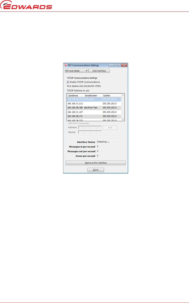
Communications between EST and the connected equipment utilise an Edwards® proprietary protocol named 'Pump Local Format' (or PLF).
To configure PLF communications, launch EST and select the 'Options' menu. Select the utility 'PLF Communications Settings'
Figure 6 - PLF RS232 communications windows (initial settings)
Upon opening the PLF Communications Settings window for the first time, settings panes for both LON and serial communications will be displayed.
To enable your communications hardware, proceed as follows:
Installation
© Edwards Limited 2017. All rights reserved.© Edwards Limited 2017. All rights reserved. |
Page 7 |
Edwards and the Edwards logo are trademarks of Edwards Limited. |
|

D372-17-880 Issue C
Installation
Figure 7 - Serial communication settings
Follow the above steps to select desired serial port (note that actual port allocations may differ from the example shown above).Successful Communications will be indicated by the interface status changing to 'open (packed)'. Additionally, the 'Detected Equipment' window will show the identity of the connected equipment (see example below).
Figure 8 - Detected equipment (serial)
Page 8 |
© Edwards Limited 2017. All rights reserved. |
|
Edwards and the Edwards logo are trademarks of Edwards Limited. |
D372-17-880 Issue C
If the pump is iGX, iXH, iXL, iXM, GXS or CXS, then Ethernet communications can be used to talk to the pump. This is the fastest communications protocol for these pump types and is therefore recommended. To select Ethernet communications with a pump, choose PLF over TCP/IP as the PLF communications settings.
If the pump isn't already connected to an Ethernet network, plug a cable directly from the pump to the Ethernet socket on your PC. If it is on a network, connect your PC to the switch nearest the pump with an Ethernet cable.
Figure 9 - Adding Ethernet PLF communications
To find the IP address of your pump, connect a PDT and look under Setup->IP Config->IP address.
This IP address should be listed as one of the addresses in the table TC/IP Addresses to use. Select it and then press 'Done' to enable communications. Alternatively, you can identify the pump using its serial number and then press 'Done'.
If the pump is not in the list of IP addresses, then the PC's net mask or IP address domain might not be set correctly. In that case, go to the Windows Control Panel/Network and Sharing Center and select the ethernet connection to be used. Edit the Local Area Connection properties by pressing the LAN settings button, selecting Internet Protocol Version 4 (TCP/IPv4) from the list and press 'Properties'. Enter a compatible IP address to make the pump visible (one with the same Subnet ID. If both your PC and the pump are already on the same network, then you shouldn't need to do this.
Installation
© Edwards Limited 2017. All rights reserved.© Edwards Limited 2017. All rights reserved. |
Page 9 |
Edwards and the Edwards logo are trademarks of Edwards Limited. |
|

D372-17-880 Issue C
Installation
Figure 10 - Setting the IP address on a Windows PC
Once you have Ethernet communications with the pump, then the pump will be listed with its IP address in the left hand side 'Equipment' box in the EST window.
Figure 11 - Equipment list in EST window
Page 10 |
© Edwards Limited 2017. All rights reserved. |
|
Edwards and the Edwards logo are trademarks of Edwards Limited. |

D372-17-880 Issue C
3Equipment support toolkit - main features
Figure 12 - Typical EST main view (iGX pump connected)
Key to EST Main View:
1.Main Menu and navigation icons - provides access to Monitoring menu, Service menu, Utility menu, Logger menu, options and Help. Each menu will be covered in more detail in later sections.
features main - toolkit support Equipment
© Edwards Limited 2017. All rights reserved.© Edwards Limited 2017. All rights reserved. |
Page 11 |
Edwards and the Edwards logo are trademarks of Edwards Limited. |
|
D372-17-880 Issue C
features main - toolkit support Equipment
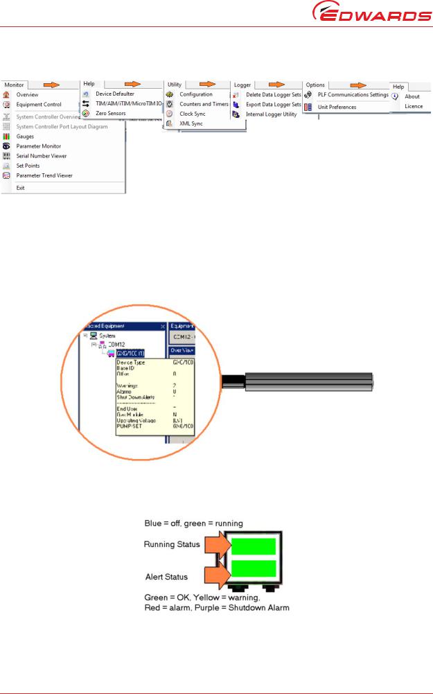
Figure 13 - EST menus
2.Equipment Control - enables the pump to be started and stopped and provides feedback of pump status. The user can also take control from another control source such as a pump display terminal (PDT).
3.Detected Equipment. The currently connected equipment is shown here. Placing your mouse pointer directly over the equipment name will display a pop-up window showing details of the connected device.
Figure 14 - Device information pop-up window
The equipment icon gives an instant indication of the running status and the alert status. When connected to equipment hosting multiple devices, a separate icon will be shown for each device.
Figure 15 - Detected equipment icon
Page 12 |
© Edwards Limited 2017. All rights reserved. |
|
Edwards and the Edwards logo are trademarks of Edwards Limited. |

D372-17-880 Issue C
Figure 16 - Detected equipment, system controller example
4.Main window. The example in figure 19 shows the default Overview page. Different pages (or tools) can be chosen from the icons or from the menu system. The various tools available will be described in later sections of this manual.
5.Alert handler - lists alerts as they occur and provides a simple alert administration facility. The user can clear individual alerts, all alerts or all inactive alerts. Clearing active alerts will result in the alerts re-appearing in the alert handler as they are broadcast from the connected equipment. The Alert Handler is covered in more detail in a later section.
6.Communications Activity Window - shows message activity between EST and connected equipment.
7.Indicators to show when last XML synchronisation occurred and status of EST Licence. The XML files contain equipment-specific messages that are used by EST.
features main - toolkit support Equipment
© Edwards Limited 2017. All rights reserved.© Edwards Limited 2017. All rights reserved. |
Page 13 |
Edwards and the Edwards logo are trademarks of Edwards Limited. |
|

D372-17-880 Issue C
This page has been intentionally left blank.
Page 14 |
© Edwards Limited 2017. All rights reserved. |
|
Edwards and the Edwards logo are trademarks of Edwards Limited. |
D372-17-880 Issue C
4 Using the monitoring tools
EST provides a comprehensive set of tools to monitor connected equipment. The tools can be accessed via the Monitoring menu shown below:
Figure 17 - The monitoring menu
The monitoring menu is split into two sections:
The top section contains the 'default' tools that normally occupy the application - these tools are enabled and shown at their maximum size when the application is first opened
The lower section of the monitoring menu lists a selection of single-task monitoring tools that enable the user to monitor equipment data in more detail
The following sections explain how to use each tool.
tools monitoring the Using
© Edwards Limited 2017. All rights reserved.© Edwards Limited 2017. All rights reserved. |
Page 15 |
Edwards and the Edwards logo are trademarks of Edwards Limited. |
|
Loading...