

Page 1

Data Power Solutions
Installation Guide
Issue: IPN 997-00012-41D
Issue Date: December 2006
Eaton Corporation
Telecommunications Solutions Division
www.powerware.com
DCinfo@eaton.com
Page 2

Eaton Corporation disclaims any liability for direct, indirect, incidental, special or
consequential damages arising out of the application or use of any information contained
in this document. The foregoing disclaimer applies to damages or personal injury,
property damage, loss of operation, loss of profits, loss of product or loss of time, whether
incurred by the purchaser, the purchaser’s employees or third party.
Information in this document does not constitute a warranty, representation or guarantee
concerning the suitability or performance of Powerware products. No such warranty,
representation or guarantee is expressed or implied.
Information contained in this document is subject to change without further notice.
Powerware and DCTools are trade names, trademarks, and/or service marks of Eaton
Power Quality Corporation or its subsidiaries and affiliates. Unless otherwise noted,
brands, product names, trademarks or registered trademarks are the property of their
respective holders.
Subject to the right to use its equipment, Eaton Corporation does not convey any right,
title or interest in its intellectual property, including, without limitation, its patents,
copyrights and know-how.
No part of this document may be reproduced or transmitted in any form, by any means or
for any purpose other than the Purchaser’s personal use, without the express written
permission of Eaton Corporation.
Copyright © 2005-2006 Eaton Corporation
All Rights Reserved
Page 3

.
Purpose
This guide provides instructions to correctly install, commission and operate Data Power
Solutions.
Audience
This guide is intended for use by IT professionals who have a sound working knowledge of
safe working practices.
Scope
This guide covers installation, commissioning and operation of Data Power Solutions,
controlled by SM45 supervisory modules.
About This Guide
It does not cover:
• Installation and characterization of batteries.
• Changing the pre-configured configuration values. For full details on changing the pre-
configured configuration values, refer to the SM45 Front Panel Menu Structure (on the
inside back cover) or DCTools online help.
Related Information
DCTools Online Help
Application Note AN0080: Ventilation of VRLA Batteries
Reporting Problems with This Guide
Please use the fax or email addresses below to report any problems you find in this guide.
Powerware DC Marketing Services
FAX: ++64 3 343 5660
EMAIL: DCMarketingNZ@eaton.com
Copyright © 2005-2006 Eaton Corporation. All Rights Reserved.
IPN 997-00012-41D December 2006
i
Page 4

About This Guide
For Further Information and Technical Assistance
Eaton recognizes the need to keep you informed about the availability of current product
information
For up-to-date product information and a complete listing of worldwide sales offices, visit
the Powerware website at: http://www.powerware.com
For comprehensive product data sheets and application notes please contact your local
Powerware DC product representative or email: DCinfo@eaton.com
For technical assistance, contact your local Powerware DC product representative in the first
instance, alternatively phone (++64) 3 343-7448 or email CustomerServiceNZ@eaton.com
.
ii
Copyright © 2005-2006 Eaton Corporation. All Rights Reserved.
IPN 997-00012-41D December 2006
Page 5

.
About This Guide
Purpose......................................................................................................................................i
Audience ...................................................................................................................................i
Scope..........................................................................................................................................i
Related Information.................................................................................................................i
Reporting Problems with This Guide....................................................................................i
For Further Information and Technical Assistance............................................................ii
Chapter 1 General Description
Overview...............................................................................................................................1-1
Data Power Solutions Product Range...............................................................................1-2
APS3-05X (Rack-Mounted Versions)........................................................................................1-3
APS3-06X (Desktop Versions)...................................................................................................1-4
APS6-05X (Rack-Mounted Versions)........................................................................................1-5
Access Power Rectifiers.......................................................................................................1-6
SM45 Supervisory Module.................................................................................................1-7
Low Voltage Disconnect (if applicable)............................................................................1-8
Chapter 2 Pre-Installation
Overview...............................................................................................................................2-1
Warnings...............................................................................................................................2-2
Inspecting the Equipment and Reporting Damage.........................................................2-6
Table of Contents
Chapter 3 Installation
Overview...............................................................................................................................3-1
Mounting the Power System..............................................................................................3-2
DC Installation Practices.....................................................................................................3-3
Connecting the DC Load Cables........................................................................................3-3
APS3-05X and APS6-05X (Rack-Mounted Versions)..............................................................3-4
APS3-06X (Desktop Versions)...................................................................................................3-5
Installing the External Batteries (if applicable)................................................................3-7
Connecting the Battery Cables (if applicable)..................................................................3-8
Installing the Battery Temperature Sensor (if batteries are fitted)..............................3-10
Connecting the Power System to the AC Supply..........................................................3-12
Chapter 4 Commissioning
Overview...............................................................................................................................4-1
Inserting the Access Power Rectifiers...............................................................................4-2
Pre-Power-Up Check...........................................................................................................4-3
Applying AC Power............................................................................................................4-4
Configuring the Power System for Operation.................................................................4-4
Using the Front Panel Keypad..................................................................................................4-4
Using DCTools............................................................................................................................4-5
Applying DC Power to the Load.......................................................................................4-8
Copyright © 2005-2006 Eaton Corporation. All Rights Reserved.
IPN 997-00012-41D December 2006
iii
Page 6

Table of Contents
Chapter 5 Operations
Overview...............................................................................................................................5-1
About the SM45 Front Panel ..............................................................................................5-2
The Keypad and LED Indicators..............................................................................................5-2
The Display Indicators............................................................................................................... 5-2
The Audible Indicator................................................................................................................ 5-3
Display Time-out........................................................................................................................ 5-3
Changing the Display Contrast................................................................................................ 5-3
About Display Modes..........................................................................................................5-4
Changing Display Modes..........................................................................................................5-4
Scrolling within a Display Mode.............................................................................................. 5-4
Using Edit Mode......................................................................................................................... 5-4
Viewing System Values (Main Display Mode)................................................................5-5
Viewing Alarms and System Status Messages (Status View Mode)............................5-6
Viewing and Editing Configuration Parameters.............................................................5-7
Chapter 6 Communications
Overview...............................................................................................................................6-1
Communications Options...................................................................................................6-2
DCTools Setup......................................................................................................................6-3
SM45 Ethernet Setup...........................................................................................................6-3
Setting Up SNMP Traps......................................................................................................6-4
Entering the “sysObjectID” of a Power System...............................................................6-5
Synchronizing the SM45 Real-time Clock........................................................................6-6
Chapter 7 Maintenance
Overview...............................................................................................................................7-1
Troubleshooting...................................................................................................................7-2
Replacing a Rectifier............................................................................................................7-6
Removing a Rectifier.................................................................................................................. 7-6
Inserting a Rectifier.................................................................................................................... 7-8
Replacing AC Input Fuses..................................................................................................7-9
Replacing the SM45 Real-time Clock Battery.................................................................7-10
Appendix A Glossary of Alarms
Appendix B Control Function Glossary
Battery Current Limit (BCL).....................................................................................................B-1
Battery Test..................................................................................................................................B-1
Equalize.......................................................................................................................................B-1
Low Volts Disconnect................................................................................................................B-2
Temperature Compensation.....................................................................................................B-2
Appendix C Specifications
Equipment Incident Report
Worldwide Support
iv
Copyright © 2005-2006 Eaton Corporation. All Rights Reserved.
IPN 997-00012-41D December 2006
Page 7

Overview
Topic Page
Data Power Solutions Product Range 1-2
Access Power Rectifiers 1-6
SM45 Supervisory Module 1-7
Low Voltage Disconnect (if applicable) 1-8
Chapter 1
General Description
Copyright © 2005-2006 Eaton Corporation. All Rights Reserved.
IPN 997-00012-41D December 2006
1-1
Page 8

General Description
Data Power Solutions Product Range
Data Power Solutions provide high reliability 48 V DC power for Power over Ethernet,
network, data and telecommunications equipment.
Each power system includes AC/DC rectifier modules, a supervisory module to provide
control and communications functions, circuit breakers to protect the output cabling, and
output terminals to connect the cables to the DC powered equipment and optional batteries.
Six models (with eight variants each) are available, as shown on the following three pages.
• APS3-058-x – rack-mounted version, without battery option
• APS3-059-x – rack-mounted version, with battery option
• APS3-060-x – desktop version, without battery option
• APS3-061-x – desktop version, with battery option
• APS6-058-x – rack-mounted version, without battery option
• APS6-059-x – rack-mounted version, with battery option
Where “–x” indicates the model variant with the following type and number of circuit
breakers:
x Number of 25A
Circuit
Breakers
Number of 6A
Circuit
Breakers
0 4 4
1 5 3
2 6 2
3 7 1
4 8 0
5 3 5
6 2 6
7 1 7
8 0 8
AC Input: Data Power Solutions can be powered by a wide range of AC power distribution
systems such as single-phase, two-phase, three-phase (L-N) and three-phase (L-L).
Depending on the nominal voltage of the AC supply (120 V or 240 V), the power systems are
equipped with either APU48 or APR48 rectifiers. Fused AC power sockets (one per rectifier)
are available for connecting the power system to the AC supply.
DC Output: Eight floating DC outlets are available for connecting equipment power cables.
Each DC outlet is protected by a corresponding 6 A or 25 A load circuit breaker. Any
combination of 6 A or 25 A rated load circuit breakers (up to a maximum of eight) can be
fitted, depending on customer requirements.
Battery Option: External VRLA 48 V batteries can be connected to APS3-059, APS3-061 and
APS6-059 models to provide backup power during AC outages. The battery float voltage is
temperature compensated.
1-2
Copyright © 2005-2006 Eaton Corporation. All Rights Reserved.
IPN 997-00012-41D December 2006
Page 9
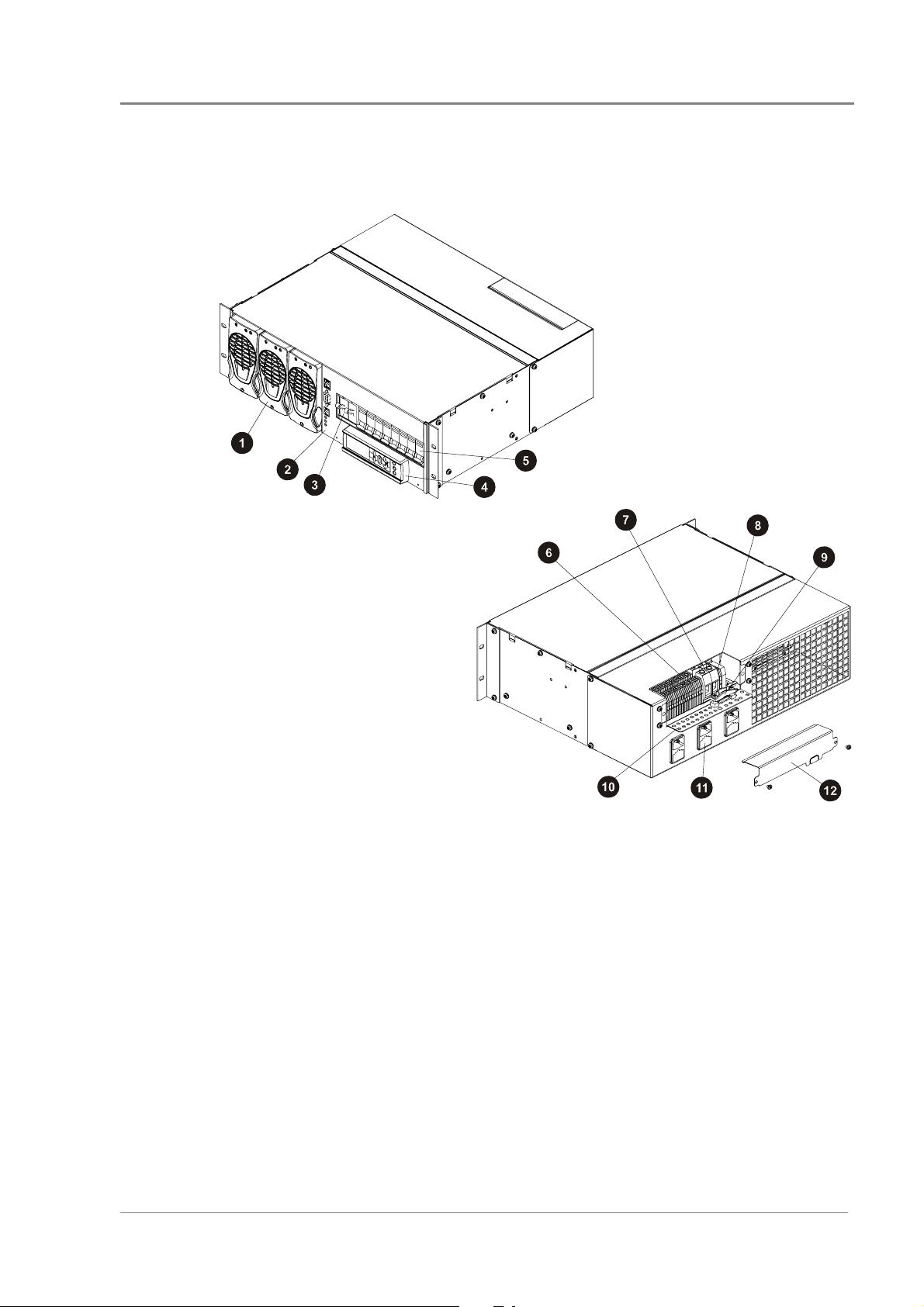
APS3-05X (Rack-Mounted Versions)
Data Power Solutions Product Range
Up to three Access Power Rectifiers, numbered 1
"
to 3 from left to right (see page 1-
SM45 Supervisory Module (see page 1-
#
One 2-pole Battery Circuit Breaker
$
(APS3-059 only)
SM45 Display Module with keypad and LED
%
indicators (see Chapter 5)
Load Circuit Breakers – any combination of 6 A
!
or 25 A rated circuit breakers up to a maximum of
eight, depending on customer requirements
Copyright © 2005-2006 Eaton Corporation. All Rights Reserved.
IPN 997-00012-41D December 2006
6)
7)
16 DC Load Terminal Blocks (2 per DC Outlet)
&
Two Battery Terminal Blocks (APS3-059 only)
3
Two Battery Temperature Sensor Terminal
4
Blocks (APS3-059 only)
Battery Cable Clamp (APS3-059 only)
5
Cable Support Bracket
'
Three fused AC Power Sockets (one per rectifier)
(
and labeled K1 to K3. K1 powers Rectifier 1, etc.
DC Output Cover (remove to access DC Output
)
terminations)
1-3
Page 10
General Description
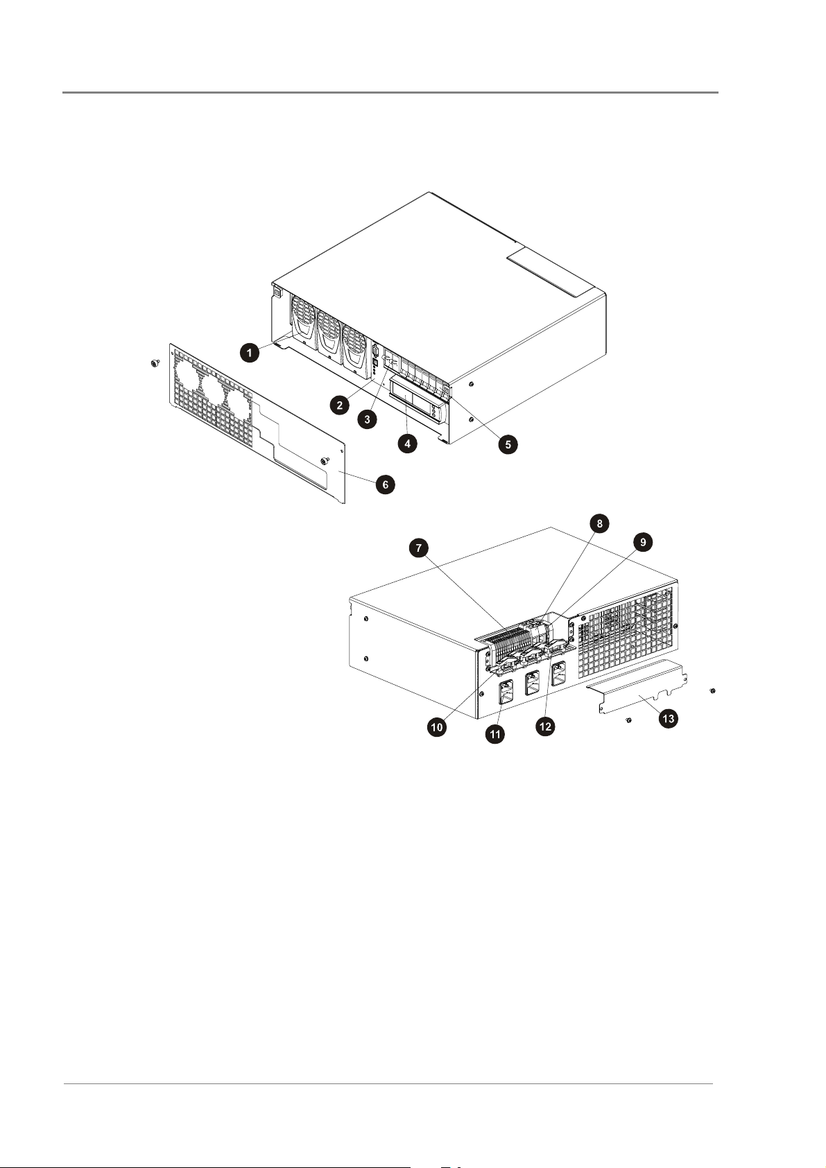
APS3-06X (Desktop Versions)
Up to three Access Power Rectifiers, numbered 1
"
to 3 from left to right (see page 1-
SM45 Supervisory Module (see page 1-
#
One 2-pole Battery Circuit Breaker
$
(APS3-061 only)
SM45 Display Module with keypad and LED
%
indicators (see Chapter 5
Load Circuit Breakers – any combination of 6 A
!
or 25 A rated circuit breakers up to a maximum of
eight, depending on customer requirements
Front Cover
&
)
)
6
16 DC Load Terminal Blocks (2 per DC Outlet)
3
Two Battery Terminal Blocks (APS3-061 only)
)
7
4
Two Battery Temperature Sensor Terminal
5
Blocks (APS3-061 only)
Four Nylon Strain Relief Clamps
'
Three fused AC Power Sockets (one per rectifier)
(
and labeled K1 to K3. K1 powers Rectifier 1, etc.
One Battery Cable Clamp (APS3-061 only)
)
DC Output Cover (remove to access DC output
*
terminations)
1-4
Copyright © 2005-2006 Eaton Corporation. All Rights Reserved.
IPN 997-00012-41D December 2006
Page 11
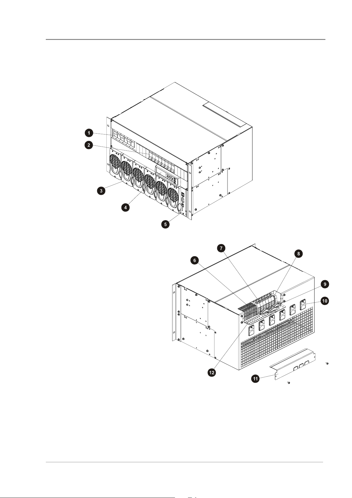
APS6-05X (Rack-Mounted Versions)
Data Power Solutions Product Range
Three 2-pole Battery Circuit
"
Breakers (APS6-059 only)
Load Circuit Breakers – any
#
combination of 6 A or 25 A
rated circuit breakers up to a
maximum of eight, depending
on customer requirements
Up to six Access Power Rectifiers,
$
numbered 1 to 6 from left to right
(see page 1-
SM45 Display Module with
%
keypad and LED indicators
(see Chapter 5)
SM45 Supervisory Module
!
(see page 1-
6)
7)
& 16 DC Load Terminal Blocks
(2 per DC Outlet)
Six Battery Terminal Blocks
3
(APS6-059 only)
Two Battery Temperature Sensor
4
Terminal Blocks (APS6-059 only)
Three Battery Cable Clamps
5
(APS6-059 only)
Six fused AC Power Sockets (one per rectifier) and labeled K1 to K6. K1 powers Rectifier 1, etc.
'
DC Output Cover (remove to access DC output terminations)
(
Cable Support Bracket
)
Copyright © 2005-2006 Eaton Corporation. All Rights Reserved.
IPN 997-00012-41D December 2006
1-5
Page 12
General Description
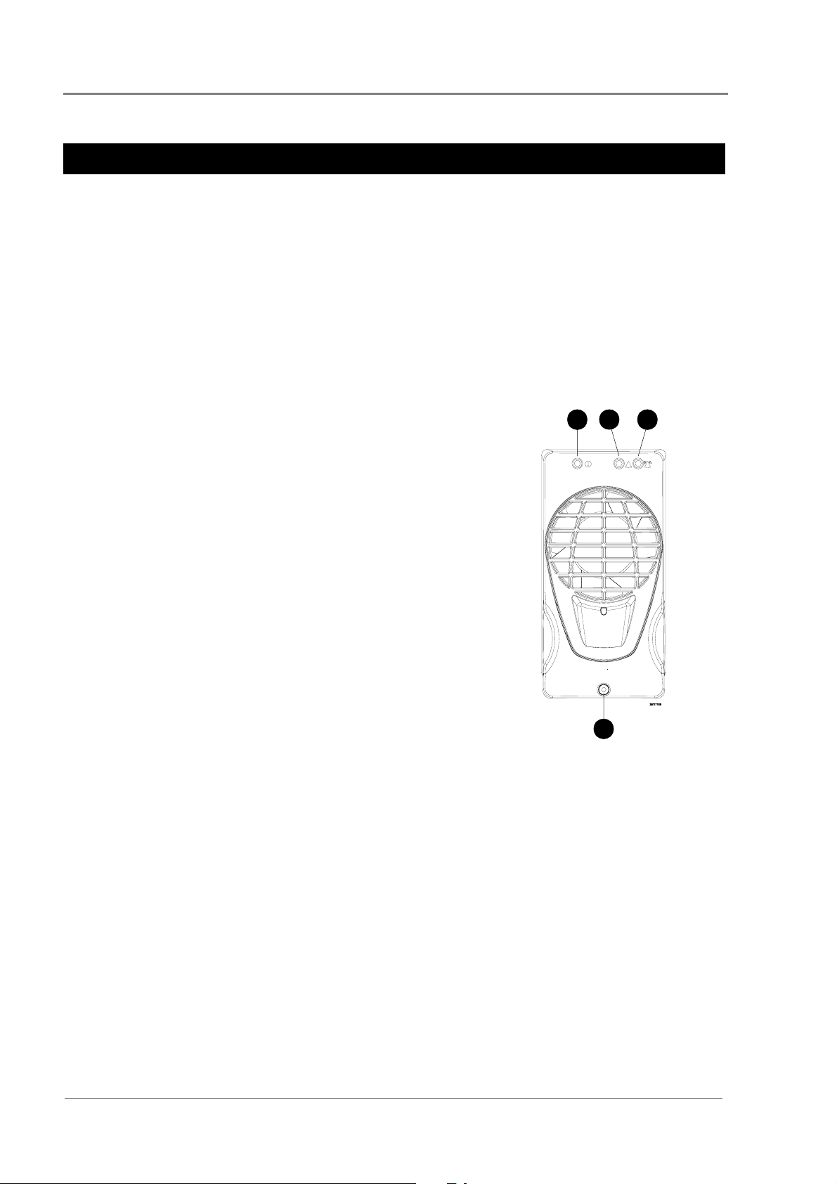
Access Power Rectifiers
Two types of fan-cooled, hot-pluggable Access Power Rectifiers are available.
• APU48 – 48 V, 720 W, (120 - 240 V AC)
• APR48 – 48 V, 1500 W, (208 - 240 V AC)
There are three status indicator LEDs on the Access Power Rectifier front panel (Power On,
Urgent Alarm and Non-Urgent Alarm).
Details about replacing a rectifier can be found in Chapter 7.
Power On LED (Green) – indicates that the rectifier is
"
powered.
Non-Urgent Alarm LED (Yellow) – indicates non-critical
#
conditions, such as:
• Rectifier in power/current limit mode
(This normally happens for a short period of time
when the batteries are recharging.)
• Rectifier operating in temperature turndown mode,
because of high ambient temperature or low AC
supply voltage
2
1
3
Urgent Alarm LED (Red) – indicates critical fault
$
conditions, that require urgent attention, such as:
• Rectifier failed
• Rectifier shut down
• AC supply failed (green LED off)
• Very high AC supply voltage
• DC overvoltage
% Retaining Screw (loosen to remove rectifier)
4
1-6
Copyright © 2005-2006 Eaton Corporation. All Rights Reserved.
IPN 997-00012-41D December 2006
Page 13
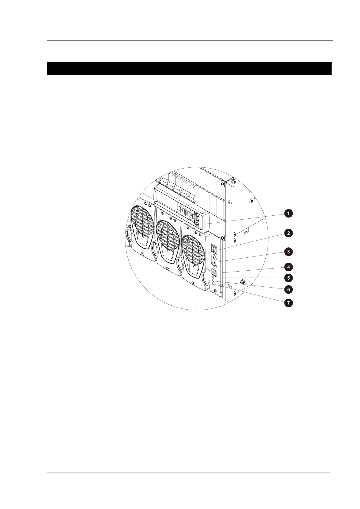
SM45 Supervisory Module
The SM45 supervisory module is an advanced control and monitoring solution for Data
Power Solutions.
It provides a full suite of advanced communications options, including built-in Ethernet
interface, Web server and SNMP agent. Details about the communications options can be
found in Chapter 6.
Alarm notifications may be by SNMP traps.
The SM45 has an onboard audible indicator and two alarm LEDs. Details about the SM45
front panel can be found in Chapter 5.
SM45 Supervisory Module
" Display Module with Keypad (see Chapter 5)
# Ethernet Interface
$ RS-232 Serial Interface
! Power On LED (green)
& Non-urgent Alarm LED (yellow)
3 Urgent Alarm LED (red)
% Not used
Copyright © 2005-2006 Eaton Corporation. All Rights Reserved.
IPN 997-00012-41D December 2006
1-7
Page 14

General Description
Low Voltage Disconnect (if applicable)
APS3-059, APS3-061 and APS6-059 models are equipped with a Low Voltage Disconnect
(LVD) module.
The LVD disconnects the batteries at the LVD disconnect voltage to prevent damage to the
batteries due to excessive deep discharge. After the batteries are disconnected, they recover
to their open-circuit voltage. The LVD reconnects the batteries automatically after the AC
supply is restored. After the batteries are reconnected, the power system recharges the
batteries and powers the loads.
Both the LVD disconnect and reconnect voltages are configurable. The default LVD
disconnect voltage is set to 44 V and the reconnect voltage to 48 V. This hysteresis band
ensures that the open-circuit recovery of the discharged batteries does not rise above the
LVD reconnect voltage.
1-8
Copyright © 2005-2006 Eaton Corporation. All Rights Reserved.
IPN 997-00012-41D December 2006
Page 15

Overview
Topic Page
Warnings 2-2
Inspecting the Equipment and Reporting Damage 2-6
Chapter 2
Pre-Installation
Copyright © 2005-2006 Eaton Corporation. All Rights Reserved.
IPN 997-00012-41D December 2006
2-1
Page 16

Pre-Installation
Warnings
This section contains important warnings relating to:
• AC Inputs
• Equipment Classification
• Batteries (if applicable)
• DC Outputs
• Rectifiers
• Location and Environment
• Servicing
• EMC Compliance
AC Inputs
• Desktop Versions:
Pluggable Type A: Except for 120V input, if APS3-06X power systems are fitted with
three rectifiers, then only two AC power cords may be connected to one building
branch circuit. The third AC power cord must be connected to a separate building
branch circuit. Failure to do so voids all safety approvals.
• The maximum earth leakage current of each Access Power Rectifier is 1.5 mA. Ensure
that any upstream Residual Current Devices (RCDs) are appropriately rated.
• The AC power cords (supplying the power system) must be suitably rated for the
environment and AC power distribution system. In addition, these AC power cords
must be approved and installed to comply with local wiring regulations.
• The earth conductor of each AC power cord must have a minimum cross sectional
area of 1 mm
• The maximum length of each AC power cord should not exceed 3m (10 feet), unless
local wiring regulations permit otherwise.
• Ensure that the AC supply is disconnected from those fused AC power sockets before
checking or replacing their respective fuses.
• Each socket, K1 to K3 (APS3), and K1 to K6 (APS6), contain two fuses, FS1 and FS2.
CAUTION: DOUBLE-POLE / NEUTRAL FUSING
• Use only 15 A, 250 VAC, 6.3 x 32 mm, fast-acting fuses of the same type (Bussman
ABC-15 or Littelfuse 314-015 Type 3AB) for continued protection against risk of fire.
2
(0.00155 in2).
Equipment Classification
• Data Power Solutions are classified as “Class 1” equipment that must be provided
with an earth connected to the “Protective Earthing Conductor” in the building
wiring. The earth conductor of each AC power cord must be connected to the
“Protective Earthing Conductor” in the building wiring.
2-2
• APS3-06X (desktop versions) are classed as “Pluggable equipment Type A” and
intended for use as “Desktop units”. All other units, APS3-05X and APS6-05X are
“Pluggable Equipment Type B” or for “Permanently connection” in host equipment.
Copyright © 2005-2006 Eaton Corporation. All Rights Reserved.
IPN 997-00012-41D December 2006
Page 17

Warnings
Batteries (if applicable)
• Always install the batteries according to the relevant battery manufacturer’s
instructions.
• Batteries are powerful sources of energy and present a potential electrical shock and
energy hazard. The energy hazard is always present, even if the batteries are not
connected. Avoid short circuiting terminals of opposite polarity.
• Batteries are heavy, awkward to handle and can cause personal injury. To prevent
back injury, use correct lifting and bending techniques when moving batteries. If the
batteries are too heavy to move, request assistance. Always comply with the relevant
company rules or local regulations.
• Remove or cover rings, wristwatch and other metal jewelry that might be exposed to
battery terminals, before installing batteries.
• Do not wear synthetic clothing when installing batteries.
• Always use insulated tools.
• Only use a clean soft damp cloth for cleaning the batteries. Do not use cleaning
detergents or chemicals.
• When unpacking the batteries inspect them carefully for leaks, corrosion and possible
damage. Report any damage or other battery related problems immediately to your
battery supplier.
• Do not remove the factory-fitted transit insulation covers from the batteries until
access to the battery terminals is required.
• Do not place tools, loose cables or metal objects (such as interconnecting bars) on top
of batteries.
• Do not drop tools, loose cables or metal objects onto intercell connections or terminals
of opposite polarity.
• Only terminate cables and interconnecting bars after confirming that the termination
will not create a short circuit.
• Always tighten the battery terminal bolts according to the battery manufacturer’s
specification. Failing to do so can cause erratic battery performance, possible damage
to the battery, and/or personal injury.
• Always ensure that any shrouding supplied with the batteries is correctly fitted to
cable connectors.
Copyright © 2005-2006 Eaton Corporation. All Rights Reserved.
IPN 997-00012-41D December 2006
2-3
Page 18

Pre-Installation
DC Outputs
• The DC outlets are floating to meet the isolation requirements for powering Power
• On APS3-06X (desktop versions), run the load cables through the supplied nylon
Rectifiers
• To reduce the risk of electric shock and maintain optimum system cooling, always
• To avoid electrical shock, do not place hands inside the rectifier shelf.
• Rectifier cases may exceed 100ºC (212ºF), especially after prolonged operation. Use
over Ethernet IEEE802.3af compatible devices.
In non-Power over Ethernet applications the positive or negative output of the DC
outlets can be referenced to earth, if required.
strain relief clamps. Failure to fit the strain relief clamps and using the incorrect
torque setting for tightening their captive screws voids all safety approvals.
cover empty rectifier slots with blanking panels (Part Number: IPN 621-05722-63A).
suitable gloves to remove the hot rectifier.
• Do not attempt to disassemble rectifiers. Return them, (in their original packaging)
along with the completed Equipment Incident Report, to your local Powerware DC
product representative for replacement or repair.
Location and Environment
• Data Power Solutions (rack-mounted and desktop versions) meet the safety and fire
enclosure requirements (as specified in AS/NZS 60950.1, EN 60950-1, IEC 60950-1
and UL 60950-1). Always mount APS3-05X and APS6-05X powers systems in 19-inch
wide host equipment racks (enclosed or open type) securely bolted to the floor and
position the desktop versions (APS3-06X) on a surface that supports the weight (12kg
/ 26lb) of the power system.
• To maintain optimum system cooling, keep the front and rear of the power system
clear from walls or other equipment. The minimum recommended clearance distance
at the front and rear of the power system is 50 mm (2”). No top and bottom clearance
is required.
• The location must provide adequate airflow around the unit, in an atmosphere free
from excessive dust, corrosive fumes or conductive contaminants.
• Dust build-up within the DC power system may cause premature failure. In dusty
environments filter the ventilation air entering the equipment room. Ensure regular
cleaning of the air filters.
2-4
• Do not allow water or any foreign object to enter the power system. Do not place
objects containing liquid on top of or near the unit.
• Flooded cell and VRLA lead acid batteries can emit explosive gases and must be
installed with adequate ventilation. Refer to the battery manufacturer or supplier for
advice on minimum ventilation levels, or refer to Application Note AN0080 available
from Eaton.
Copyright © 2005-2006 Eaton Corporation. All Rights Reserved.
IPN 997-00012-41D December 2006
Page 19

Warnings
Servicing
• Data Power Solutions contain hazardous voltages. Do not attempt to disassemble or
service the unit if you are not qualified. Only service personnel of Eaton
Corporation’s Telecommunications Solutions Division or their authorized service
agents are permitted to service the unit.
• If the power system requires servicing other than external battery or rectifier
replacement, isolate the unit first, as follows:
1 Unplug the AC supply cords from the AC power outlets.
2 Disconnect the external batteries, by switching off the battery circuit breakers.
EMC Compliance
• Data Power Solutions may be used in close proximity to other electronic equipment
provided installation is carried out according to instructions in this manual.
However, proper installation and compliance with EMC standards does not
guarantee that the power system will not respond to electromagnetic disturbances, or
will not cause interference to other equipment in a particular installation.
• Data Power Solutions comply with part 15 of the FCC (Federal Communications
Commission) rules. Operation is subject to the following two conditions:
1 This device may not cause harmful interference, and
2 This device must accept any interference received, including interference that
may cause undesired operation.
• Changes or modifications to Data Power Solutions not approved by Eaton
Corporation could void FCC authority to operate that equipment.
• Data Power Solutions have been tested and found to comply with the limits for a
Class B digital device, pursuant to part 15 of the FCC Rules. These limits are designed
to provide reasonable protection against harmful interference in a residential
installation. This equipment generates, uses, and can radiate radio frequency energy
and, if not installed and used in accordance with the instructions, may cause harmful
interference to radio communications. However, there is no guarantee that the
interference will not occur in a particular installation. If this equipment does cause
harmful interference to radio or television reception, which can be determined by
turning the equipment off and on, the user is encouraged to try to correct the
interference by one or more of the following measures:
Reorient or relocate the receiving antenna.
Increase the separation between the equipment and receiver.
Connect the equipment into an outlet on a circuit different f rom that to which the
receiver is connected.
Consult the dealer or an experienced radio/TV technician for help.
Copyright © 2005-2006 Eaton Corporation. All Rights Reserved.
IPN 997-00012-41D December 2006
2-5
Page 20

Pre-Installation
Inspecting the Equipment and Reporting Damage
Unpack the power system and inspect it carefully for possible damage that may have
occurred while in transit.
Next, check the equipment against the packing list (supplied with the equipment) and
ensure that you have received the correct type of Access Power Rectifiers (either APR48 or
APU48).
Report any damage or incorrect shipment immediately, using a copy of the Equipment
Incident Report (at the back of this guide) to supply all relevant details. Fax the completed
form to your local Powerware DC product representative.
Keep the original packaging. You will need it if any equipment needs to be returned to your
local Powerware DC product representative.
2-6
Copyright © 2005-2006 Eaton Corporation. All Rights Reserved.
IPN 997-00012-41D December 2006
Page 21

Overview
Topic Page
Mounting the Power System 3-2
DC Installation Practices 3-3
Connecting the DC Load Cables 3-3
Installing the External Batteries (if applicable) 3-7
Connecting the Battery Cables (if applicable) 3-8
Installing the Battery Temperature Sensor (if batteries are fitted) 3-10
Connecting the Power System to the AC Supply 3-12
Chapter 3
Installation
Copyright © 2005-2006 Eaton Corporation. All Rights Reserved.
IPN 997-00012-41D December 2006
3-1
Page 22
Installation
Mounting the Power System
Location and Environment
Data Power Solutions (rack-mounted and desktop versions) meet the safety and fire
enclosure requirements (as specified in AS/NZS 60950.1, EN 60950-1, IEC 60950-1 and
UL 60950-1).
• Rack-Mounted Versions: APS3-05X and APS6-05X series power systems may be
mounted in 19-inch wide host equipment racks (enclosed or open type) securely bolted
to the floor.
• Desktop Versions: APS3-06X series power systems may be positioned on any surface
that supports the weight of the power system.
The location must provide adequate airflow around the unit, (as per Clearance Requirements
below) in an atmosphere free from excessive dust, corrosive fumes, or conductive
contaminants.
Dust build-up within the DC power system may cause premature failure. In dusty
environments filter the ventilation air entering the equipment room. Ensure regular cleaning
of the air filters.
VRLA lead acid batteries can emit explosive gases and must be installed with adequate
ventilation. Refer to the battery manufacturer or supplier for advice on minimum ventilation
levels, or refer to Application Note AN0080 available from Eaton.
Clearance Requirements
All Data Power Solutions (rack-mounted and desktop versions) require the following
minimum clearances:
• Front and Rear Clearance – 50 mm (2”) from walls and other equipment, required for
optimum system cooling and access.
• Top and Bottom Clearance – None
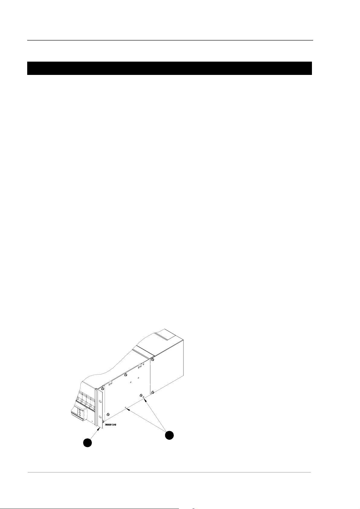
Rack Installation (rack-mounted versions only)
" APS3-05X and APS6-05X power systems come
pre-assembled with two 19-inch rack-mounting
brackets.
# The two rack-mounting brackets can be moved
backwards and lined up with alternative
bracket-mounting holes, to provide greater
mounting flexibility. Ensure the same screws are
used.
2
1
3-2
Copyright © 2005-2006 Eaton Corporation. All Rights Reserved.
IPN 997-00012-41D December 2006
Page 23

Important Notes for Rack Mounted Systems:
• If this DC power system is installed in a closed or multi-unit rack assembly ensure that
the ambient temperature is less than 40°C.
• Ensure that the air flow is not restricted.
• Ensure that the system’s weight is adequately and evenly supported.
• Take note of the maximum AC current stated on the nameplate. Ensure that the AC
supply is correctly rated.
• Ensure that reliable earthing is maintained. Carefully check earth continuity from the
branch circuit to the DC power system.
DC Installation Practices
Before you start connecting the DC load and battery cables (if applicable) to a power system,
please read the following DC Installation Practices:
• On APS3-06X (desktop versions), run the DC load cables through the supplied nylon
strain relief clamps at the rear. (See page 3clamps and using the incorrect torque setting for tightening their captive screws voids all
safety approvals.
DC Installation Practices
5 for details.) Failure to fit the strain relief
• To easily distinguish between positive and negative load cables, we recommend using
cables with different colors (as specified by local wiring regulations). The same applies
to battery cables (if applicable).
• To reduce inductive coupling, separate DC load, battery and communications cabling
from AC supply cables. If the cables have to cross, run them at right angles to the AC
supply cables.
• In order to minimize parasitic cable inductance and reduce electromagnetic interference
(EMI), all DC load cables should be routed in close proximity to one another, and large
current loops should be avoided. The same applies to battery cables (if applicable).
Connecting the DC Load Cables
Eight DC outlets (labeled 1 to 8) are available for connecting your equipment power cables.
Each DC outlet is protected by a corresponding 6 A or 25 A circuit breaker (accessible from
the DC distribution at the front). The current rating of the corresponding circuit breaker
determines the current rating of a DC outlet.
The DC outlets are floating to meet the isolation requirements for powering
Power over Ethernet IEEE802.3af compatible devices. In non-Power over Ethernet applications
the positive or negative output of the DC outlets can be referenced to earth, if required.
Copyright © 2005-2006 Eaton Corporation. All Rights Reserved.
IPN 997-00012-41D December 2006
3-3
Page 24
Installation
DC Load Cable Specifications
No DC load cables are supplied.
DC load cables are sized differently, depending on whether you connect to 6A or 25A
DC outlets. All DC load cables must meet the following specifications and no other cable
sizes must be used.
6 A DC Outlets:
25 A DC Outlets:
UL 1015*, 18 AWG (1mm
UL 1015*, 12 AWG (4mm
2
), multi-strand cable
2
), multi-strand cable
Cable Length:
*Required to maintain approval compliance.
3m (10 feet) maximum
APS3-05X and APS6-05X (Rack-Mounted Versions)
3
2
1
4
" Terminate the negative load cable(s) at the (-) terminal block(s) of the DC outlet(s).
# Terminate the positive load cable(s) at the (+) terminal block(s) of the DC outlet(s).
Ensure that the polarity at the DC outlet(s) matches the power input polarity of your
equipment. Connecting reverse polarity equipment power cables to the DC outlets of a
power system might cause damage to your equipment. Such damage is not covered by
our warranty.
Ensure that the correct cable sizes have bee used (18 AWG for 6 A outlets and 12 AWG
for 25 A outlets).
$ To ensure reliable connections at the terminal blocks of the DC outlets, torque the clamp-screws
0.4 – 0.6 Nm (3.5 – 5.3 lb-in).
% Use cable-ties (not supplied) and the provided cable-tie holes on the cable support bracket to tie
down the load cables.
3-4
Copyright © 2005-2006 Eaton Corporation. All Rights Reserved.
IPN 997-00012-41D December 2006
Page 25

APS3-06X (Desktop Versions)
Before proceeding check you have:
• 4 x load cable clamps
• 8 x 25mm blunt ended screws
• 8 x 5mm and 4 x 10mm cable sleeves (50mm long)
Depending on the cables sizes, not all sleeves will be required.
Connecting the DC Load Cables
• 1mm
• 4mm
2
(18 AWG) cable for connection to 6A outlets
2
(12 AWG) cable for connection to 25A outlets
Step 1 - Fit load cable clamps
Insert the square ends of the load cable clamps into the holes in the back of the
system.
Engage two turns of each retaining screw. This will ensure that the clamp does
not move when the wires and sleeves are inserted.
Fit all clamps even if you do not use them all. Tighten unused clamps to prevent
access to the DC outputs.
Step 2 - Strip cable ends
Strip approximately 10mm (3/8”) from the cable ends. We recommend fitting cable ferrules
over the cable ends.
Copyright © 2005-2006 Eaton Corporation. All Rights Reserved.
IPN 997-00012-41D December 2006
3-5
Page 26

Installation
Step 3 – Fit cables and sleeves
To maintain safety approvals insert only the following numbers of cables per clamp,
with sleeves where applicable. This will ensure that cables are retained correctly in
their clamps.
Feed the cables through the clamps as follows, depending on cable size:
2
(18 AWG) – 2 cable pairs* per clamp:
1mm
2
4mm
(12 AWG) – 1 or 2 cable pairs per clamp
Do not tighten the clamps at this stage.
Step 4 – Terminate cables
" 2 x 5mm sleeves
# 10mm sleeve
* If only one cable pair is required
then use a dummy pair with
sleeves to make up the space.
Terminate the negative load cable(s) at the (-) terminal block(s) of the DC
outlet(s).
Terminate the positive load cable(s) at the (+) terminal block(s) of the DC
outlet(s).
Tighten the terminal screws. Required torque: 0.4 – 0.6 Nm (3.5 – 5.3 lb-in).
Ensure that the polarity at the DC outlet(s) matches the power input polarity of your
equipment. Connecting reverse polarity equipment power cables to the DC outlets of
a power system might cause damage to your equipment. Such damage is not covered
by our warranty.
Ensure that the correct cable sizes have been used (1mm
2
and 4mm
/12 AWG for 25 A outlets).
2
/18 AWG for 6 A outlets
Step 5 – Arrange sleeves and tighten clamp screws
Arrange the sleeves so that they are all within 10mm (3/8”) of the terminals.
Tighten all cable clamp screws. Required torque: 1.5 – 2 Nm (13.2 – 17.7 lb-in).
Tighten the screws of any unused clamps to prevent access to the DC output
terminations.
Procedure complete
3-6
Copyright © 2005-2006 Eaton Corporation. All Rights Reserved.
IPN 997-00012-41D December 2006
Page 27

Installing the External Batteries (if applicable)
Installing the External Batteries (if applicable)
This section applies to APS3-059, APS3-061 and APS6-059 power systems only.
One 48 V battery string can be connected to APS3-059 and APS3-061 and up to three 48 V
battery strings to APS6-059 power systems.
A 48 V battery string consists of either:
• 24 Valve Regulated Lead Acid (VRLA) 2 V cells or
• Four VRLA 12 V monoblocs
Because of the wide range of battery types and sizes available, we do not supply batteries
with the above mentioned power systems and therefore do not cover battery installation in
this guide. Always install batteries according to the relevant battery manufacturer’s
instructions.
Battery Sizing
Battery manufacturers provide various types of information for sizing batteries such as
constant current discharge and constant power discharge data. Your battery supplier will be
able to assist you with sizing the battery for your application.
Before a battery can be sized, the following information is required.
• Required backup time
• Minimum cell voltage (typically 1.83 V per Cell)
• Load profile
• Operating temperature
In telecommunications and data applications most loads are constant power for a specified
backup time. Therefore, for sizing a battery for the required backup time, constant power
discharge data should be used.
For charging the battery, constant current discharge data should be used. When charging
the battery, battery current limit should be used to set the battery charge to no more than the
maximum recharge specified by the battery manufacturer.
Batteries for use in North America must be a UL recognized type, category BAZR2.
Battery Location
Valve Regulated Lead Acid (VRLA) batteries emit very small amounts of hydrogen gas into
the surrounding atmosphere under normal float charging conditions. For that reason
batteries should never be installed in a sealed enclosure or cabinet.
Install the batteries in a well-ventilated location to prevent accumulation of hydrogen gas to
flammable or explosive levels.
Building air conditioning and ventilation systems already in place for optimum equipment
operation and comfort of personnel usually meet or exceed VRLA battery ventilation
requirements. For specific battery ventilation requirements, always refer to the battery
manufacturer’s installation instructions.
Copyright © 2005-2006 Eaton Corporation. All Rights Reserved.
IPN 997-00012-41D December 2006
3-7
Page 28

Installation
Avoid:
• Installing the batteries next to any heating source or under air ducts.
• Exposing part of a battery string to direct sunlight.
• Any other locations that would cause temperature variations within the batteries.
Battery Fault Protection
A fault protection device (such as a circuit breaker or fuse) must be fitted in series with one
of the battery cables of each battery string.
The fault protection device must be:
• Located as close as practical to the corresponding battery string output terminal and
• Capable of disconnecting the potential fault current of the battery string.
The battery circuit breaker(s) of the power system can not be considered as the fault
protection device for the battery string(s) and associated wiring.
The interrupt rating of the battery circuit breaker(s) fitted within the power systems is 10 kA.
Therefore, the maximum potential short-circuit current of a 48 V battery string must be
limited to less than 10 kA or the total internal impedance of the battery string should be
greater than 5.7 mΩ.
If a smaller rated external fault protection device is used, then batteries with appropriate
internal impedance need to be selected.
Connecting the Battery Cables (if applicable)
This section applies to APS3-059, APS3-061 and APS6-059 power systems only.
Before You Start
Ensure that all the circuit breakers at the front of the power system and the external battery
circuit breaker (close to the battery output terminals) are switched OFF.
Before proceeding check you have:
• Battery cable clamp(s) (one for APS3 models, three for APS6-059)
• 2 x 25mm blunt ended screws per clamp
• 1 x 16mm cable sleeve (50mm long) per clamp
• Battery cable (see specifications below).
Battery Cable Specifications
No battery cables are supplied with APS3-059, APS3-061 and APS6-059 power systems. All
battery cables must meet the following specifications and no other cable sizes must be used.
Cable Style and Size:
UL 1283*, 4 AWG (25mm
2
), multi-strand cable
Cable Length:
*Required to maintain approval compliance.
Copyright © 2005-2006 Eaton Corporation. All Rights Reserved.
3-8
3m (10 feet) maximum
IPN 997-00012-41D December 2006
Page 29

Connecting the Battery Cables (if applicable)
Step 1 - Prepare cable clamp
Cut off the two inside posts of the battery cable clamp to enable the battery
cables and sleeve to fit.
Step 2 – Strip cable and fit sleeve
Strip approximately 17mm (3/4”) of the insulation from the cable ends. We
recommend fitting cable ferrules over the cable ends.
Feed both battery cables through the 16mm sleeve.
Step 3 – Terminate cable
Terminate the positive battery cable at the Battery (+) terminal block.
Terminate the negative battery cable at the Battery (-) terminal block.
Tighten the terminal screws. Required torque: 2.5 - 3 Nm (22.1 – 26.5 lb-in).
Ensure that the polarity at the battery terminal blocks matches the polarity of the
external battery. Connecting a reverse polarity battery to a power system will cause
damage to the rectifier modules. Such damage may not be covered by the warranty.
" 16mm battery cable sleeve.
# Battery cable clamp with posts removed.
Step 4 – Arrange sleeve and clamp the battery cables
Arrange the cable sleeve so that it is within 10mm (3/8”) of the terminals.
Tighten the cable clamp screws. Required torque: 1.5 – 2 Nm (13.2 – 17.7 lb-in).
Copyright © 2005-2006 Eaton Corporation. All Rights Reserved.
IPN 997-00012-41D December 2006
3-9
Page 30

Installation
Step 5 – Repeat for other battery cables (if required)
Repeat the above procedure to connect up to three battery strings to an APS6-
059 power system.
Step 6 – Remove knockout and fit cover
Remove the battery cable knockout(s) on the DC output cover.
" Battery cable knockout.
Remove any sharp edges, in particular the remaining knock-out webs.
Fit the DC output cover.
Procedure complete
Installing the Battery Temperature Sensor (if batteries are fitted)
This section applies to APS3-059, APS3-061 and APS6-059 power systems only.
Each APS3-059, APS3-061 and APS6-059 power system is supplied with a battery
temperature sensor and standard 2 m (6.5 feet) long cable (factory-fitted to the sensor).
Longer cables are available from your local Powerware DC product representative or you
can make up your own. We strongly recommend limiting the maximum cable length of the
battery temperature sensor to 20 m (65 feet) because of noise considerations.
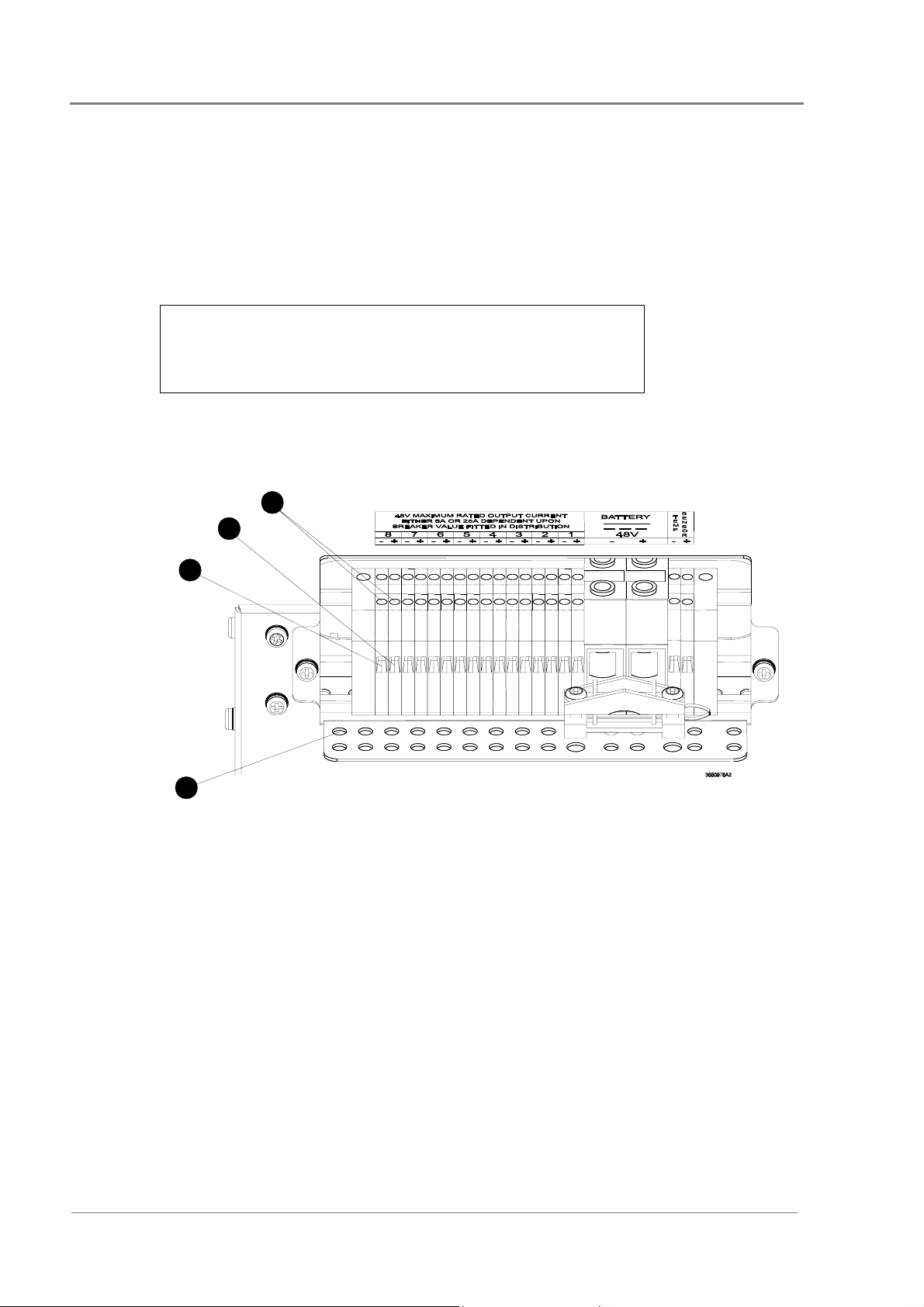
Connecting the Battery Temperature Sensor Cable
There are two screw-clamp terminal blocks at the rear of APS3-059, APS3-061 and APS6-059
power systems for terminating the battery temperature sensor cable, as shown below.
The two terminal blocks are labeled TEMP SENSOR (+) and TEMP SENSOR (-).
3-10
Copyright © 2005-2006 Eaton Corporation. All Rights Reserved.
IPN 997-00012-41D December 2006
Page 31

Installing the Battery Temperature Sensor (if batteries are fitted)
" Terminate the Black/White wire at TEMP SENSOR (+) and the Black wire at
TEMP SENSOR (-), as shown.
# To ensure reliable connections at the battery temperature sensor terminal blocks, torque the
clamp-screws 0.4 – 0.6 Nm (3.5 – 5.3 lb-in).
$ Use cable-ties (not supplied) and the provided cable-tie holes on the cable support bracket to tie
down the battery temperature sensor cable.
On APS3-061 power systems, there is a cable-tie hole on the bracket behind the battery
cable clamp, to tie down the battery temperature sensor cable.
Mounting the Battery Temperature Sensor
The battery temperature sensor is designed to measure the average ambient temperature
around the batteries. It is important to mount the battery temperature sensor at a location
that truly reflects the average ambient temperature of the batteries.
Attaching the battery temperature sensor to the battery stand (centered and above the
batteries) may provide the most reliable temperature reading.
If possible, avoid:
• Placing the battery temperature sensor on top of battery cases.
• Attaching the battery temperature sensor to battery cables, terminals or interconnecting
bars.
• Exposing the battery temperature sensor to direct sunlight and drafts from the airconditioning system or open windows.
• Running the battery temperature sensor cable along power or earth cables.
Copyright © 2005-2006 Eaton Corporation. All Rights Reserved.
IPN 997-00012-41D December 2006
3-11
Page 32

Installation
Connecting the Power System to the AC Supply
Data Power Solutions can be connected to single-phase (L-N), two-phase (L-L), three-phase
(L-N) and three-phase (L-L) AC power distribution systems.
Fused AC power sockets (one per rectifier) are available for connecting the power system to
the AC supply. These fused AC power sockets are labeled K1 to K3 on APS3 and K1 to K6
on APS6 power systems. AC power socket K1 powers Rectifier 1, etc. (See Chapter 1 for
location of Rectifier 1.)
No AC power cords are supplied with the power systems.
AC Supply Requirements
• AC Power Cords – The AC power cords (supplying the power system) must be suitably
rated for the environment and AC distribution system. In addition, these AC power
cords must be approved and installed to comply with local wiring regulations. (See
Appendix C for maximum AC input current specifications.)
The earth conductor of each AC power cord must have a minimum cross sectional area
of 1 mm
The maximum length of each AC power cord should not exceed 3m (10 feet), unless local
wiring regulations permit otherwise.
• Desktop Versions – If APS3-06X power systems are fitted with three rectifiers, then only
two AC power cords may be connected to one building branch circuit. The third AC
power cord must be connected to a separate building branch circuit. Failure to do so
voids all safety approvals.
• Earthing – Data Power Solutions are classified as “Class 1” equipment that must be
provided with an earth connected to the “Protective Earthing Conductor” in the building
wiring. The earth conductor of each AC power cord must be connected to the
“Protective Earthing Conductor” in the building wiring.
• Earth Leakage Current – The maximum earth leakage current of each Access Power
Rectifier is 1.5 mA. Ensure that any upstream Residual Current Devices (RCDs) are
appropriately rated.
AC Installation
Install all AC cabling between the AC power source and the power system according to the
AC Supply Requirements above, but do NOT switch on the AC supply at this stage.
2
(0.00155 in2).
3-12
Copyright © 2005-2006 Eaton Corporation. All Rights Reserved.
IPN 997-00012-41D December 2006
Page 33

Overview
Topic Page
Inserting the Access Power Rectifiers 4-2
Pre-Power-Up Check 4-3
Applying AC Power 4-4
Configuring the Power System for Operation 4-4
Applying DC Power to the Load 4-8
Chapter 4
Commissioning
Copyright © 2005-2006 Eaton Corporation. All Rights Reserved.
IPN 997-00012-41D December 2006
4-1
Page 34

Commissioning
Inserting the Access Power Rectifiers
Do NOT switch on the AC supply at this stage.
Step 1 – Unpack the rectifiers
Unpack the rectifiers and inspect them carefully for possible damage that may
have occurred in transit. Report any damage immediately, using a copy of the
Equipment Incident Report (located at the back of this guide) to supply all
relevant details. Fax the completed form to your local Powerware DC product
representative.
Keep the original packaging. You will need this if any equipment needs to be
returned to your nearest authorized service agent for replacement or repair.
Step 2 – Align the rectifier with the burst-out guides in the shelf
Step 3 – Push in the rectifier
1 Slowly push in the rectifier, sliding it along the burst-out guides, as shown
To avoid injury to your hands, keep your fingers clear, as shown in
the diagram below.
below, until it plugs firmly into the backplane connector.
4-2
2 Tighten the rectifier retaining screw with a Pozidriv® screwdriver.
Copyright © 2005-2006 Eaton Corporation. All Rights Reserved.
IPN 997-00012-41D December 2006
Page 35

Pre-Power-Up Check
Use the checklist below to complete initial checks before progressing further.
Checklist
Pre-Power-Up Check
All AC and DC cabling is installed
All cabling is neat and correctly insulated
DC battery and load cabling has the correct polarity
All panels are in place and all empty rectifier slots are covered
with blanking panels
The AC supply to the power system is switched OFF
All circuit breakers at the front of the power system are
switched OFF
Batteries (if fitted) are isolated from the power system
Copyright © 2005-2006 Eaton Corporation. All Rights Reserved.
IPN 997-00012-41D December 2006
4-3
Page 36

Commissioning
Applying AC Power
1 Switch on the AC supply.
2 Check that each rectifier starts up and that the green
the red urgent
troubleshooting section in Chapter 7).
3 Check that the SM45 supervisory module has powered up and that the green
Power On LED on both the SM45 and the display module is on.
and yellow non-urgent alarm LEDs are off. (If not consult the
Depending on your configuration settings, the urgent and/or non-urgent alarm LED(s)
may also be on.
4 Check that all installed rectifiers are communicating and that the SM45 supervisory
module has correctly registered all rectifiers, by viewing the individual rectifier currents
in Main Display Mode. (See front panel menu structure on inside front cover or
Viewing System Values in Chapter 5 for details.)
If no load is connected each rectifier will show 0 A.
Configuring the Power System for Operation
Each power system is supplied with a pre-loaded configuration file.
It is important that the settings of this configuration file are checked/verified and changed as
required for site-specific conditions. In particular settings that may affect the performance
and life expectancy of the battery must be checked and set according to the battery
manufacturer’s recommendations.
Power On LED is on and both
Only those configuration parameters that are most likely to be changed on-site can be
configured from the front panel. For entering and editing of all other configuration
parameters (such as mapping of alarms to relays and setting up communications) a laptop
computer and the latest version of DCTools is required. The latest version of DCTools can be
downloaded from http://www.powerware.com/downloads
We recommend using DCTools for configuring your power system for operation.
Using the Front Panel Keypad
Scroll through the SM45’s Configuration Mode and change the configuration settings as
required.
A list of all the configuration settings that can be changed from the front panel can be f ound
on the inside back cover.
For details about changing configuration settings from the front panel, see
Viewing and Editing Configuration Parameters in Chapter 5.
4-4
Copyright © 2005-2006 Eaton Corporation. All Rights Reserved.
IPN 997-00012-41D December 2006
Page 37

Using DCTools
Before you start, you need
• A PC (preferably a laptop) with the latest version of DCTools installed.
• A null modem cable
Step 1 – Connect a PC to the RS-232 port of the APS DC power system
1 Connect the null modem cable between the RS-232 port of the power system
Configuring the Power System for Operation
and the serial port of your laptop or PC.
2 Start DCTools by double clicking on the DCTools icon
Step 2 – Check that your PC port is specified correctly
1 Double-click on the DCTools icon
the DCTools Connection List. The default connection is COM1.
2 If the port properties are correct, enable the connection by selecting the
Active check box
The correct port properties are, (Protocol: S3P and S3P Address: 0).
If the port properties are incorrect, select the relevant connection from the
Connection List and click the
dialog, edit the properties as necessary and click OK.
If the connection is successful, the DCTools System Summary (Home) screen
is displayed as shown.
of that connection.
in the Windows™ task bar to display
toolbar button. In the Comms Properties
on the desktop.
Copyright © 2005-2006 Eaton Corporation. All Rights Reserved.
IPN 997-00012-41D December 2006
4-5
Page 38

Commissioning
Step 3 – Check through the loaded configuration and make changes as required
Check through the loaded configuration in DCTools by clicking on the hotlinks
at the top of the DCTools System Summary (Home) screen and make changes as
required.
The DCTools System Summary (Home) screen below shows the main
configuration hotlinks, followed by a list of what can be configured under each
hotlink.
Hotlink Click to …
Configuration
Alarms Configure system alarms (see Example 1)
Analogs
Digitals
Relays
Toggle relay states when performing a Relay Test and
Control
LVD
Enable/disable LVD(s) and to configure the LVD settings
Rectifiers
Enter site specific information and synchronize the SM45
real-time clock with the internal UTC time of your PC under
Identity
Set up Ethernet communications and SNMP traps under
Communications
Configure analog inputs, current inputs and external analog
inputs
Set-up user alarms
configure external digital inputs
Configure the settings of control functions such as Manual
Equalize, Temperature Compensation, Battery Test, Fast
Charge, Battery Current Limit and Active Voltage Control.
Configure rectifier settings
, and sysObjectID under SNMP
4-6
Copyright © 2005-2006 Eaton Corporation. All Rights Reserved.
IPN 997-00012-41D December 2006
Page 39

Configuring the Power System for Operation
Example 1 Reconfiguring System Alarms
In general reconfiguring system alarms requires the following:
• Changing the urgency (Disabled, Relay Only, Urgent or
Non Urgent)
• Setting the alarm thresholds and recognition times
For example, to reconfigure an alarm, follow the steps below.
1 From the DCTools System Summary (Home) screen, click
the Alarms
hotlink. The Alarm Table screen is then
displayed.
2 To change the urgency of an alarm, double-click on the
Urgency for that alarm, then click the
the new urgency from the popup list.
3 To change alarm thresholds and recognition times, click
the
button to the left of Alarm Configuration at the
bottom of the Alarm Table screen and change the settings
as required.
button and select
Copyright © 2005-2006 Eaton Corporation. All Rights Reserved.
IPN 997-00012-41D December 2006
4-7
Page 40

Commissioning
Applying DC Power to the Load
1 Check the DC output voltage and polarity of the power system and battery string(s).
2 Switch on the Battery MCB(s) (if fitted) and check that the Battery Fuse Fail alarm clears.
When connecting multiple battery strings in parallel to the system DC bus, ensure that
the individual strings are of similar voltage.
3 Check the Battery Current reading, if batteries are fitted. (The actual value depends on
the state of charge of the batteries.)
4 Switch on the Load MCB(s). Check that the load (the equipment) powers up and that the
Load Fuse Fail alarm clears.
5 Check the rectifier currents and verify that the load current is representative of what the
load draws and also that the power system has sufficient capacity.
6 Charge the batteries (if fitted) according to the battery manufacturer’s recommendations.
Manual Equalize can be started from DCTools or the front panel.
Manual Equalize increases the system voltage to the pre-configured equalize voltage for
the pre-configured equalize duration. After the pre-configured equalize duration has
expired, the power system voltage reverts back to normal battery float voltage
automatically.
7 Fit the DC output cover.
4-8
Copyright © 2005-2006 Eaton Corporation. All Rights Reserved.
IPN 997-00012-41D December 2006
Page 41

Overview
Topic Page
About the SM45 Front Panel 5-2
About Display Modes 5-4
Viewing System Values (Main Display Mode) 5-5
Viewing Alarms and System Status Messages (Status View Mode) 5-6
Viewing and Editing Configuration Parameters 5-7
Chapter 5
SM45 Operations
Copyright © 2005-2006 Eaton Corporation. All Rights Reserved.
IPN 997-00012-41D December 2006
5-1
Page 42

SM45 Operations
About the SM45 Front Panel
The Keypad and LED Indicators
Backlit LCD Display
"
Keypad
#
Power On LED (green) – indicates that the SM45 is powered
$
21
3
4
5
Non-urgent Alarm LED (yellow) – indicates one or more active non-urgent alarms
%
Urgent Alarm LED (red) – indicates one or more active urgent alarms
!
Scroll Keys: Press these keys to scroll through lists and menus and to increase or decrease
configuration values.
Information Key: Press this key to view status messages and a list of active alarms in Status
View Mode.
Enter Key: Press this key to go to Configuration Mode and Edit Mode, save configuration
changes, clear alarms or toggle relay states.
Escape Key: Press this key to go to Main Display Mode or cancel configuration changes.
The Display Indicators
The following display indicators may appear on the screen from time to time.
Indicates an urgent alarm.
Indicates a non-urgent alarm.
???
5-2
disconnected or unconfigured sensor.
Indicates which scroll key to press, to view further display items.
Copyright © 2005-2006 Eaton Corporation. All Rights Reserved.
IPN 997-00012-41D December 2006
Indicates that the system value cannot be displayed, because of a failed,
Page 43

The Audible Indicator
The SM45 has an onboard audible indicator.
The audible indicator informs you about pressing invalid keys and active alarms as follows:
• One beep every 2 seconds - indicates that a non-urgent alarm is active
• A continuous sound - indicates that an urgent alarm is active
An urgent alarm always overrides a non-urgent alarm.
► To disable the audible indicator (when an alarm is active)
• Press any key
At the next active alarm, the audible indicator is automatically enabled again.
Display Time-out
About the SM45 Front Panel
The SM45 has a display time-out function – that is, if no keys are pressed for a
predetermined time interval, the SM45 reverts back to the default display (total rectifier
current).
The predetermined time interval varies (according to the display mode you are in) as
follows:
• Edit Mode – no time-out
• All other display modes – 2 minutes
Changing the Display Contrast
The display contrast can be adjusted from 0 (lowest contrast) to 63 (highest contrast).
► To change the display contrast
1 Press the
2 Press the
3 Press the
4 Press either the
changes are immediately visible.)
key to enter Configuration Mode.
key to scroll down to Display Contrast.
key to enter Edit Mode.
or key to change the display contrast as appropriate. (Contrast
5 Press the
6 Press the
key to save the new value.
key to return to Main Display Mode.
Copyright © 2005-2006 Eaton Corporation. All Rights Reserved.
IPN 997-00012-41D December 2006
5-3
Page 44

SM45 Operations
About Display Modes
The SM45 front panel menu structure consists of four display modes:
• Main Display Mode – for viewing system values
• Status View Mode – for viewing system statuses as well as viewing and clearing alarms
• Configuration Mode – for viewing settings of configurable parameters
• Edit Mode – for editing the configurable parameters in Configuration Mode
For quick and easy reference, graphical representations of the menu structure are printed on
the inside front and back covers.
Changing Display Modes
► To enter a display mode
• From Main Display Mode, press the key to enter Status View Mode and Alarm Mode.
• From Main Display Mode, press the key to enter Configuration Mode and Edit Mode.
► To exit a display mode
• Press the key to return from any mode to Main Display Mode.
Scrolling within a Display Mode
► To scroll within a display mode
• Press the key to scroll up within a display mode.
• Press the key to scroll down within a display mode.
To scroll through a display mode faster, hold down the or key.
Using Edit Mode
For details about viewing and editing configuration parameters, see page 2-7.
5-4
Copyright © 2005-2006 Eaton Corporation. All Rights Reserved.
IPN 997-00012-41D December 2006
Page 45

Viewing System Values (Main Display Mode)
Viewing System Values (Main Display Mode)
Nine system values (as at right) can
be viewed in Main Display Mode.
If a system value is not available (for
example, because of an incorrectly
configured or disconnected battery
temperature sensor), the following is
displayed.
Details about the other display
indicators can be found on page 2-
Total Rectifier
Current
(Default Display)
2.
Main Display Mode
► To view system values
1 Press the
through the system values in
Main Display Mode.
2 Only six individual rectifier
currents are displayed at once.
If more than six rectifiers are
installed, press the
to scroll through the list.
3 Press the
the top of the list – total rectifier
current.
or key to scroll
key to return to
or key
Total output
power delivered
by the rectifiers
as a percentage of
available power
Individual
Rectifier
Currents
Copyright © 2005-2006 Eaton Corporation. All Rights Reserved.
IPN 997-00012-41D December 2006
5-5
Page 46

SM45 Operations
Viewing Alarms and System Status Messages (Status View Mode)
Status View Mode displays alarm and status messages.
The appearance of one of the following display indicators in Main Display Mode indicates
the presence of an alarm message.
indicates an urgent alarm
indicates a non-urgent alarm
Details about the other display indicators can be found on page 2-
Rules for displaying alarms and system status
• Active alarms are always displayed before status messages.
• Urgent alarms are always displayed before non-urgent alarms.
• Alarms with their urgency set to Disabled are not displayed.
2.
Important note about Rect Comms Lost alarm
If a rectifier is removed, a Rectifier Comms Lost alarm is displayed after 10 seconds. The
operator or installer then has the opportunity to clear the alarm immediately to prevent
triggering an external alarm device. The alarm must be cleared within the configurable
Alarm Recognition Time (default is 10 seconds), otherwise an external alarm is generated.
Rects Comms Lost is remotely displayed as Multiple Rectifier Comms Lost.
► To view and clear alarms
1 From Main Display Mode, press the
2 Press the
3 Press the
Lost, Rects Comms Lost and Battery Test Fail.)
4 Press the
key to scroll through the list of alarms.
key to clear the alarms. (Only three alarms can be cleared – Rect Comms
key to return to Main Display Mode.
key to enter Status View Mode.
For a comprehensive list of alarms (that can be displayed in Status View Mode) see
Appendix A.
► To view system status messages
1 Press the
If there are active alarms, press the
control status list is displayed after the last alarm.
2 Press the
3 Press the
5-6
key to enter Status View Mode.
key to scroll to the bottom of the alarm list. The
or key to scroll through the list of status messages.
key to return to Main Display Mode.
Copyright © 2005-2006 Eaton Corporation. All Rights Reserved.
IPN 997-00012-41D December 2006
Page 47

Viewing and Editing Configuration Parameters
Viewing and Editing Configuration Parameters
Configuration Mode displays only those configuration parameters that are most likely to be
changed on-site. Configuration parameters configurable from the front panel are changed in
Edit Mode.
For viewing and editing all other configuration parameters a laptop computer or remote
access is required. See Chapter 3 for details about the standard communications options.
► To view and edit a configuration parameter
1 From Main Display Mode, press the
2 Press the
3 Press the
4 Press either the
5 Press the
6 Press the
7 Press the
key to scroll down to the required parameter.
key to enter Edit Mode.
or key to change the value as appropriate.
key to save the new value and return to Configuration Mode, or
key to cancel the change and return to Configuration Mode.
key to return to Main Display Mode.
key to enter Configuration Mode.
Copyright © 2005-2006 Eaton Corporation. All Rights Reserved.
IPN 997-00012-41D December 2006
5-7
Page 48

SM45 Operations
5-8
Copyright © 2005-2006 Eaton Corporation. All Rights Reserved.
IPN 997-00012-41D December 2006
Page 49

Overview
Topic Page
Communications Options 6-2
DCTools Setup 6-3
SM45 Ethernet Setup 6-3
Setting Up SNMP Traps 6-4
Entering the “sysObjectID” of a Power System 6-5
Synchronizing the SM45 Real-time Clock 6-6
Chapter 6
Communications
Copyright © 2005-2006 Eaton Corporation. All Rights Reserved.
IPN 997-00012-41D December 2006
6-1
Page 50

Communications
Communications Options
The SM45 supervisory module communicates to a designated PC (running the DCTools
software) via a:
• Standard RS-232 serial interface, or
• Ethernet 10BaseT interface, both accessible from the front panel
Shown below are the two standard communications options.
Direct Connection
Ethernet
6-2
Copyright © 2005-2006 Eaton Corporation. All Rights Reserved.
IPN 997-00012-41D December 2006
Page 51

DCTools Setup
For your chosen communications option, configure the communications settings, in DCTools
according to the table below.
Then check that DCTools communicates correctly.
Properties Direct Connection Ethernet
Comms Enabled True True
Protocol S3P S3P
Connect Using COM1 Local Network
S3P Address 0 0
Server IP Address – 10.64.129.1 (See Note 1)
Server Port – 14000
DCTools Setup
Telnet – Cleared
Note 1:
Allocated by network administrator
SM45 Ethernet Setup
Before an SM45 supervisory module can communicate over an IP network with DCTools, the
SM45 must be set up for Ethernet communications.
Use the front panel or DCTools for configuring the SM45 supervisory module for Ethernet
communications.
Setup of Ethernet communications requires the following:
• The network administrator assigning a unique IP address to each SM45 supervisory
module to be connected to the IP network
• Setting the assigned IP address for each SM45
• Setting the net mask / subnet mask and gateway address for each SM45 as appropriate
► To configure the SM45 for Ethernet communications using DCTools
1 From the DCTools System Summary (Home) screen, click the Configuration
then Communications
2 Under Ethernet, enter the assigned IP address, subnet mask and gateway address.
Copyright © 2005-2006 Eaton Corporation. All Rights Reserved.
to display the Communications view.
IPN 997-00012-41D December 2006
hotlink and
6-3
Page 52

Communications
Setting Up SNMP Traps
The SM45 supervisory module can be configured to send alarms as SNMP traps to up to
eight different SNMP trap receivers.
To send alarms as SNMP traps, first set up Ethernet communications (see page 6-
3 for
details), and then use DCTools to set up SNMP traps as follows:
1 From the DCTools System Summary (Home) screen, click the Configuration
Communications
2 Click the
hotlink to display the Communications view.
button to the left of SNMP to display the SNMP configuration view.
and then
3 Do not change the default settings of SNMP Read Community (public) and SNMP
Write Community (private), unless requested by the network administrator.
4 Configure Trap Repeat and Trap Repeat Rate as appropriate.
5 For each receiver, configure the following parameters using the configuration guidelines.
Parameter Configuration Guidelines
Name Enter the name of the SNMP trap receiver (20 characters
maximum).
Level SNMP Trap Level – controls reporting of specific events for each
receiver as follows:
• Select All Events And Alarms to receive events and urgent
and non-urgent alarms. (Typically events are status
messages such as Equalize Active.)
• Select Urgent And Non Urgent Alarms to receive both
urgent and non-urgent alarm notifications.
• Select Urgent Alarms Only to receive only urgent alarm
notifications.
• Select Disabled to temporarily disable notifications to the
receiver.
IP Address Enter the IP address of the trap receiver that has been assigned
by the network administrator.
Port Enter the port number of the trap receiver that has been
assigned by the network administrator.
Trap Community A form of password. Use public, unless the network
administrator has assigned a new password.
Mode Select:
• Normal Traps for sending traps to any network
management system, except PowerManagerII
• Acknowledged Summary Trap for sending traps to
PowerManagerII only
6-4
Copyright © 2005-2006 Eaton Corporation. All Rights Reserved.
IPN 997-00012-41D December 2006
Page 53

Entering the “sysObjectID” of a Power System
Entering the “sysObjectID” of a Power System
“sysObjectID” is a unique identifier that allows the network management system to identify
an item (in this case a power system) on the network.
The unique identifiers are listed in the table below.
APS3-058:
1.3.6.1.4.1.1918.10.1
APS3-059:
APS3-060:
APS3-061:
APS6-058:
APS6-059:
1.3.6.1.4.1.1918.10.2
1.3.6.1.4.1.1918.10.3
1.3.6.1.4.1.1918.10.4
1.3.6.1.4.1.1918.10.5
1.3.6.1.4.1.1918.10.6
► To enter the “sysObjectID” of a power system using DCTools
1 From the DCTools System Summary (Home) screen, click the Configuration
then Communications
2 Click the
3 Click the
button to the left of SNMP and scroll down to the bottom of the SNMP view.
button to the left of sysObjectID Component to display the sysObjectID
entry view.
4 Enter only the last three parts of the power system’s unique identifier into the
appropriate sysObjectID fields. (See Example 1 below.)
Example 1
to display the Communications view.
The unique identifier of an APS6-058 power system is
1.3.6.1.4.1.1918.10.5.
The last three parts (1918.10.5) are entered as shown below.
hotlink and
Copyright © 2005-2006 Eaton Corporation. All Rights Reserved.
IPN 997-00012-41D December 2006
6-5
Page 54

Communications
Synchronizing the SM45 Real-time Clock
The SM45 features a battery-backed real-time clock for accurate date-time stamping of all
alarms and control processes. Battery back up ensures that the date and time is maintained
while the SM45 is not powered.
The real-time clock is set to Coordinated Universal Time (UTC) during manufacture. If
required, the time can be corrected by synchronizing it with the internal UTC time of your
PC.
PC real-time clocks are not always accurate. Ensure that the time of your PC is correct before
synchronizing.
► To synchronize the SM45 real-time clock using DCTools
1 Ensure that the SM45 is powered and connected to DCTools.
2 From the DCTools System Summary (Home) screen, click the Configuration
then Identity
3 Under Time Synchronization, click the Synchronize button to synchronize the real-time
clock.
to display the System Identification view.
hotlink and
6-6
Copyright © 2005-2006 Eaton Corporation. All Rights Reserved.
IPN 997-00012-41D December 2006
Page 55

Overview
Topic Page
Troubleshooting 7-2
Replacing a Rectifier 7-6
Replacing AC Input Fuses 7-9
Replacing the SM45 Real-time Clock Battery 7-10
Chapter 7
Maintenance
Copyright © 2005-2006 Eaton Corporation. All Rights Reserved.
IPN 997-00012-41D December 2006
7-1
Page 56

Maintenance
Troubleshooting
Use the table below to troubleshoot minor power system installation and operational
problems. If you still cannot solve a problem, contact your local Powerware DC product
representative for assistance.
Problem Possible Cause/s Required Action
All rectifiers are off
(no LEDs on) and
SM45 display is blank
Green LED of one or
more rectifiers is off
Rectifier red LED on
AC power to the system is off
and the batteries are fully
discharged or disconnected.
AC power to rectifier(s) off or
one or more phases are off
Rectifier is not fully inserted. Check that the rectifier is fully
Internal rectifier fault Remove the rectifier and insert
Very low AC voltage or AC
supply failed
AC overvoltage None. The power system will
Restore AC power.
Restore AC power.
inserted.
another one in the same slot.
If the second rectifier operates
normally, the first rectifier is
faulty and must be returned to
your local Powerware DC
product representative.
Check the AC supply. The
power system will return to
normal operation when the AC
supply has returned to within its
specified AC input voltage
range. See Appendix C.
return to normal operation when
the AC supply has returned to
within its specified AC input
voltage range, as specified in
Appendix C.
Rectifier shut down Check if a rectifier has in fact
been shut down, using DCTools.
If yes, turn on the rectifier using
DCTools.
Rectifier(s) failed Use DCTools to determine if a
rectifier has failed or has been
shut down.
If a rectifier has failed, replace it.
If a rectifier has been shut down,
refer to required action for
Rectifier Shut Down.
DC overvoltage Remove and re-insert rectifier(s)
after approximately 5 seconds.
7-2
Copyright © 2005-2006 Eaton Corporation. All Rights Reserved.
IPN 997-00012-41D December 2006
Page 57

Troubleshooting
Problem Possible Cause/s Required Action
Rectifier yellow LED
on
High system output
voltage
Rectifier power limit is active. Check if the power system is
recovering from a recent AC
power outage. The power system
may still be charging the
batteries after the power outage.
No further action is required.
Check that the rectifier capacity
of the power system is not
exceeded. Additional rectifiers
may be required.
Rectifier temperature
turndown is active, due to
low AC supply voltage or
excessive ambient
temperature.
None. The power system will
return to normal operation when
the AC supply has returned to
within its rated AC input voltage
or operating temperature range,
as specified in Appendix C.
Equalize, Fast Charge and/or
Temperature Compensation
Disable active processes if not
required.
process is active
Incorrect float voltage setting
at supervisory module
Check the float voltage setting of
the supervisory module.
Low system output
voltage (rectifiers not
in current limit)
Low system output
voltage and rectifier
yellow LEDs are on
(rectifiers are in
current limit).
Record new setting.
Faulty rectifier Remove rectifier modules one at
a time. (The output voltage
returns to normal when faulty
rectifier is removed.)
Replace faulty rectifier.
Rectifiers not on Restore AC power.
Battery Test and/or
Temperature Compensation
Disable active processes if not
required.
process is active.
Incorrect float voltage setting
at supervisory module.
Check the float voltage setting of
the supervisory module.
Record new setting.
Load is too high for rectifier
capacity.
Battery is recharging after AC
power outage.
continued
Reduce load or add rectifier
modules.
Check battery has recharged
within expected time.
Copyright © 2005-2006 Eaton Corporation. All Rights Reserved.
IPN 997-00012-41D December 2006
7-3
Page 58

Maintenance
Problem Possible Cause/s Required Action
SM45 does not
correctly register the
current shunts and
the displayed values
are over range.
SM45 display is
blank.
SM45 green
Power On LED off.
SM45 red LED on SM45 “Urgent Alarm” is active. Check the type of “Urgent
SM45 yellow LED
on
Local/External current shunt
selector switches in the wrong
position.
Faulty SM45 display or
disconnected display loom.
SM45 is not powered Check the SM45 card is fully
SM45 is faulty. Contact your local Powerware
SM45 “Non-Urgent Alarm” is
active.
Contact your local Powewrware
DC product representative.
Contact your local Powewrware
DC product representative.
inserted into the backplane.
DC product representative.
Alarm” using DCTools or press
the
key on the SM45 front
panel.
Check the type of “Non-urgent
Alarm” using DCTools or press
the
key on the SM45 front
panel.
No Ethernet
communications
between SM45 and
local PC
No communications
between SM45 and
local PC
Wrong IP address, netmask
and/or incompatible network
Gateway may be required
Faulty communications cable Replace faulty cable.
The Telnet Active check box in
the DCTools Comms Properties
dialog is enabled.
Incorrect cable Check that a null modem cable
Null modem cable not plugged
into PC or plugged into the
wrong port.
Communications port settings
of PC do not match that of the
RS-232 serial port of the power
system.
Incorrect S3P address. Check that the S3P address in
continued
Check the settings with the
network administrator.
Disable the Telnet Active check
box in the DCTools Comms
Properties dialog.
has been used.
Check that the null modem
cable is plugged into the PC and
into the correct port.
Reconfigure the PC port
properties (19K2 8 N 1).
DCTools is set to 0.
7-4
Copyright © 2005-2006 Eaton Corporation. All Rights Reserved.
IPN 997-00012-41D December 2006
Page 59

Troubleshooting
Problem Possible Cause/s Required Action
SM45 displays
Config Error
SM45 displays ???
Missing configuration Download the appropriate
configuration file into the SM45.
Invalid configuration Contact your local Powerware
DC product representative.
Incorrect number of cells in a
battery string – a result of a
mismatch between string
voltage and nominal rectifier
Check the number of cells in a
battery string, nominal voltage
of each cell and the nominal
voltage of the rectifiers.
output voltage.
Incorrectly configured,
disconnected or failed sensor
Configure, connect or replace
sensor.
Copyright © 2005-2006 Eaton Corporation. All Rights Reserved.
IPN 997-00012-41D December 2006
7-5
Page 60

Maintenance
Replacing a Rectifier
Access Power Rectifiers can be replaced without switching off the power system and
disconnecting the equipment it powers.
Only service personnel should replace faulty rectifiers.
This section covers the following procedures.
• Removing a Rectifier
• Inserting a Rectifier
Removing a Rectifier
To reduce the risk of electric shock and maintain optimum system cooling, always
cover empty rectifier slots with blanking panels.
To avoid electric shock do not place hands inside the rectifier shelf.
Do not attempt to disassemble faulty rectifiers. Return them, (in their original
packaging) along with the completed Equipment Incident Report, to your nearest
authorized service agent for replacement or repair.
This note applies to APS3-06X desktop versions only:
To gain access to the rectifiers, remove the front cover of the APS3-06X power system first.
Step 1 – Loosen the rectifier retaining screw with a Pozidriv® screwdriver
7-6
Copyright © 2005-2006 Eaton Corporation. All Rights Reserved.
IPN 997-00012-41D December 2006
Page 61

Step 2 – Pull out the rectifier
Replacing a Rectifier
Grip the rectifier front panel with one hand as indicated by the arrows in the
diagram below and slowly pull it out from the shelf, supporting the base of the
rectifier with your other hand.
Rectifier cases may exceed 100ºC (212ºF), especially after prolonged
operation. Use suitable gloves to remove the hot rectifier.
To avoid damage to the connector do not rest the rectifier on its connector, once
it has been removed from the shelf.
Procedure complete
You must now insert a replacement rectifier into the empty slot (see page 7-8), or fit a
blanking panel (Part Number: IPN 621-05722-63A).
Copyright © 2005-2006 Eaton Corporation. All Rights Reserved.
IPN 997-00012-41D December 2006
7-7
Page 62

Maintenance
Inserting a Rectifier
Step 1 – Align the new rectifier with the burst-out guides in the shelf
Step 2 – Push in the rectifier
1 Slowly push in the rectifier, until the rear connector of the rectifier engages
2 Tighten the rectifier retaining screw.
To avoid injury to your hands, keep your fingers clear, as shown in
the diagram below.
fully with the backplane connector.
3 Check that the rectifier’s
alarm LEDs are off.
Power On LED turns on and the and
The alarm LED turns on for about 1 second when the rectifier powers
up.
4 Fit the front cover (APS3-06X desktop versions only).
Procedure complete
7-8
Copyright © 2005-2006 Eaton Corporation. All Rights Reserved.
IPN 997-00012-41D December 2006
Page 63

Replacing AC Input Fuses
Replacing AC Input Fuses
Each AC power socket has two fuses (one in the phase (L) and another in the neutral (N) AC
input line) to protect the power system against certain internal fault conditions.
Only service personnel should replace the AC input fuses.
Ensure that the AC supply is disconnected from those fused AC power sockets
before checking or replacing their respective fuses.
CAUTION: DOUBLE-POLE / NEUTRAL FUSING
Use only 15 A, 250 VAC, 6.3 x 32 mm, fast-acting fuses of the same type
(Bussman ABC-15 or Littelfuse 314-015 Type 3AB) for continued protection against
risk of fire.
► To check and replace AC input fuses
1 Disconnect the AC power cord from the fused AC power socket of the rectifier that is not
operating.
The fused AC power sockets of APS3 power systems are labeled (K1 to K3) and
(K1 to K6) on APS6 power systems. AC power socket K1 powers Rectifier 1.
(See Data Power Solutions diagrams in Chapter 1 for location of Rectifier 1.)
2 With a suitable flat-blade screwdriver, press down the fuse drawer tab to release it from
the fuse holder.
3 Remove the fuse drawer and check both fuses.
4 Replace any blown fuses only with 15 A, 250 VAC, 6.3 x 32 mm, fast-acting fuses of the
same type (Bussman ABC-15 or Littelfuse 314-015 Type 3AB).
5 Re-insert the fuse drawer into the fuse holder and press the fuse drawer until it locks
into position.
6 Reconnect the AC power cord.
7 Check if the affected rectifier powers up and that its green
If not, then that rectifier is faulty and needs to be replaced. (See page 7about replacing a rectifier.)
If the faulty rectifier has been replaced once and the fuses of that AC power socket blow
again, then there is a problem with the internal wiring of the power system. In that
instance, contact your local Powerware DC product representative for assistance.
Power On LED is on.
6 for details
Copyright © 2005-2006 Eaton Corporation. All Rights Reserved.
IPN 997-00012-41D December 2006
7-9
Page 64

Maintenance
Replacing the SM45 Real-time Clock Battery
A 3.6 V lithium battery provides power to the real-time clock when the SM45 is not powered.
Only service personnel should replace the real-time clock battery.
The battery can be replaced with a Tadiran TL-5902/S, or equivalent ½AA non-rechargeable
lithium battery.
There is a risk of explosion if the used battery is replaced with an incorrect type.
Dispose of the used battery according to the battery manufacturer’s instructions.
7-10
Copyright © 2005-2006 Eaton Corporation. All Rights Reserved.
IPN 997-00012-41D December 2006
Page 65

AC Fail
ACD Fan Fail
Aux Temp High
Aux Temp Low
Aux Temp Sensor Fail
Appendix A
Glossary of Alarms
All rectifiers are reporting loss of AC power.
The AC Distribution cooling system or fan controller has failed.
The auxiliary temperature sensor is at a temperature above the high
temperature set point.
The auxiliary temperature sensor is at a temperature below the low
temperature set point.
The auxiliary temperature sensor is incorrectly configured,
disconnected, not fitted or faulty.
Batt Temp High
Batt Temp Low
Battery Fuse Fail
(displayed as Batt Fuse Fail)
Battery Test Active
Battery Test Fail
Equalize Active
Fast Charge Active
High Float
High Load
In Discharge
Load Fuse Fail
Low Float
Low Load
This alarm indicates either thermal runaway of the batteries or that
the batteries are operating at a temperature that may cause reduced
battery life.
This alarm indicates a risk to the battery standby power system.
Note that lower temperatures reduce the battery capacity.
The batteries may no longer be powering the load.
A Battery Test is active.
The batteries do not have the required capacity or are not operating
in a fully charged state.
An Equalize process is active.
A Fast Charge process is active.
The float voltage is above its normal range.
The bus voltage is higher than the range that is safe for a reliable
load.
The batteries are discharging.
The Load Fuse Fail digital input to the SM45 is active.
The float voltage is below its normal range.
The bus voltage is below its normal range.
Copyright © 2005-2006 Eaton Corporation. All Rights Reserved.
IPN 997-00012-41D December 2006
A-1
Page 66

Glossary of Alarms
gg
LVD1 Disconnect
LVD1 Fail
LVD1 Manual
LVD2 Disconnect
LVD2 Fail
LVD2 Manual
MOV Fail
Multiple Rectifier Comms Lost
(displayed as Rects Comms Lost)
Multiple Rectifier Fail
(displayed as Mult. Rect Fail)
Partial AC Fail
Rectifier Comms Lost
(displayed as Rect Comms Lost)
Rectifier Fail
Sensor Fail
System Overload
The operating conditions of the power system have automatically
triggered a low voltage disconnect.
LVD1 is faulty.
A local operator has manually triggered LVD1. (APS6-059 only)
The operating conditions of the power system have automatically
triggered a low voltage disconnect.
LVD2 is faulty.
A local operator has manually triggered LVD2. (APS6-059 only)
The surge protection system has failed. One or more MOV
cartridges may need to be replaced.
Normally this alarm indicates that multiple rectifiers have been
removed during routine maintenance. However, faulty rectifier
communications or losing the rectifier communications bus can also
tri
er this alarm. If removing multiple rectifiers triggers this alarm,
you can reset it from the front panel before it triggers an external
alarm.
Multiple rectifiers are faulty or their AC power has been removed
without causing partial or total AC failure.
More than 20% of the rectifiers are reporting loss of AC power or
loss of a phase.
A rectifier has been removed during routine maintenance. However,
faulty rectifier communications or losing the rectifier
communications bus can also trigger this alarm. If removing a
rectifier triggers this alarm, you can reset it from the front panel
before it triggers an external alarm.
A rectifier is faulty or its AC power has been removed without
causing partial or total AC failure. You can reset a Rectifier Fail
alarm from the front panel before it triggers an external alarm.
The current, temperature or voltage sensing system is faulty.
The power system is operating close to its maximum capacity and
more rectifiers may need to be inserted. The System Overload
threshold is configurable.
A-2
Copyright © 2005-2006 Eaton Corporation. All Rights Reserved.
IPN 997-00012-41D December 2006
Page 67

Battery Current Limit (BCL)
Battery Current Limit automatically limits the battery charge current within a configured
range (a percentage of the C10 rating of the battery) by varying the system voltage.
Enable Battery Current Limit to prevent:
• Overcharging of the batteries in under-loaded systems
• Overgassing of the batteries
BCL Engine Run Limit limits the battery charge current to a preset value, when the power
system is powered by a standby engine/alternator during an extended AC power outage. A
smaller engine/alternator set can therefore be used without excessively pulling down the
alternator voltage.
If BCL Engine Run Limit is enabled, then:
• The battery current limit process will use the Engine Run Limit as the charge parameter
rather than Battery Current Limit, and
Appendix B
Control Function Glossary
• The User Digital Input and User Alarm number (as specified by the Engine Run Digital
Battery Test
Battery Test is a preventative maintenance tool that monitors the discharge capabilities to
ensure that the condition of the battery has not deteriorated over time.
The SM45 supervisory module temporarily reduces the output voltage of the rectifiers just
below the bus voltage for a set duration. The battery now supplies power to the load. A
battery test passes if the battery capacity remains above a predetermined level for the
duration of the test.
Battery Test does NOT function during a Fast Charge or Equalize process or during the first
Equalize
Equalize charges the batteries at a higher voltage after they have been fully charged to
ensure that all individual cell voltages are the same.
Battery manufacturers recommend that batteries be equalized periodically. Refer to the
battery manufacturer’s instructions, before equalizing the batteries.
Input number) will not be available. (The default setting is Digital Input 1.)
48 hours after an AC power outage.
Copyright © 2005-2006 Eaton Corporation. All Rights Reserved.
IPN 997-00012-41D December 2006
B-1
Page 68

Control Function Glossary
Low Volts Disconnect
Low Voltage Disconnect disconnects the batteries (Battery Disconnect) or the load (Load
Disconnect), at the preset LVD disconnect voltage. This prevents damage to the batteries
due to excessive deep discharge. The LVD reconnects the batteries or loads after the AC
power is restored.
When configuring the LVD reconnect voltage, ensure that the expected open-circuit recovery
voltage of the discharged batteries does not rise above the LVD reconnect voltage.
Temperature Compensation
Temperature Compensation automatically varies the float voltage to cancel the effects of
increasing or decreasing ambient battery temperature.
As the ambient temperature of the batteries increases, the voltage required to maintain it in a
fully charged state decreases.
Enable Temperature Compensation to help maintain optimum battery capacity over a wider
temperature range, which in turn extends battery life.
B-2
Copyright © 2005-2006 Eaton Corporation. All Rights Reserved.
IPN 997-00012-41D December 2006
Page 69

Appendix C
Specifications
System AC Input
AC Input Voltage Range APU48 rectifiers: 95 – 275 V
(L-N)
rms
APR48 rectifiers: 185 – 275 V
rms
Rated AC Input Current
APS3: 21 A (7 A per AC power cord)
APS3: 10.5 A
APS3: 24 A
@ 120 V
@ 240 V
rms
rms
@ 208-240 V
with APU48 rectifiers
with APU48 rectifiers
with APR48 rectifiers
rms
APS6: 42 A
APS6: 21 A
APS6: 48 A
(7 A per AC power cord)
(3.5 A per AC power cord)
(3.5 A per AC power cord)
(8 A per AC power cord)
(8 A per AC power cord)
Frequency Range 45-66 Hz
Maximum Earth Leakage Current 1.5 mA (per Access Power Rectifier)
System DC Output
DC Output Voltage (nominal) 48 V
DC Output Power (maximum)
(L-N)
2.16 kW (with 3 APU48 rectifiers)
1.70 kW
4.32 kW
3.40 kW
APS3-058 & APS3-060
APS3-059 & APS3-061
APS6-058
APS6-059
4.50 kW
(with 3 APR48 rectifiers)
(with 3 APU48 rectifiers)
3.00 kW (with 3 APR48 rectifiers)
(with 6 APU48 rectifiers)
9.00 kW (with 6 APR48 rectifiers)
(with 6 APU48 rectifiers)
7.10 kW (with 6 APR48 rectifiers)
DC Output Voltage Range 43 - 57.5 V
Over Voltage Shutdown Trip Point 58 V
Environment
Ambient Temperature Range (operating) -10°C to +40°C [+14°F to +104°F]
Relative Humidity (operating and storage) <95% (non condensing)
Copyright © 2005-2006 Eaton Corporation. All Rights Reserved.
IPN 997-00012-41D December 2006
C-1
Page 70

Specifications
Dimensions H, W, D
APS3-058 and APS3-059 3U, 19” mounting, 390 mm [15.35”]*
APS3-060 and APS3-061 150 mm, 465 mm, 415 mm
[5.9”, 18.31”, 16.34”]*
APS6-058 and APS6-059 6U, 19” mounting, 390 mm [15.35”]*
Access Power Rectifier 3U, 66 mm [2.6”], 280 mm [11”]
* Additional clear air space is required at rear for rectifier exhaust air venting.
Weight
APS3 6 kg [13 lb]*
APS6 10 kg [22 lb]*
Access Power Rectifier 1.9 kg [4.2 lb]
* typical configuration, excluding rectifiers
APR48 Rectifiers
AC Input Voltage Range 185 – 275 V
Full output up to 50°C [122°F]
rms
150 – 185V
Full output up to 30°C [86°F]
Maximum AC Input Current 12 A
rms
rms
@ 150 V
rms
Rated Output Power 1500 W
Rated Output Current 31 A @ 48V
Preset Voltage 54.5 V
APU48 Rectifiers
AC Input Voltage Range 95 – 275 V
Full output up to 50°C [122°F]
Maximum AC Input Current 10 A
rms
rms
@ 95 V
rms
Rated Output Power 720 W
Rated Output Current 15 A @ 48V
Preset Voltage 54.5 V
Comprehensive SM45 supervisory module and Access Power Rectifier product data sheets
are available. Please contact your local Powerware DC product representative or email
DCinfo@eaton.com
C-2
Copyright © 2005-2006 Eaton Corporation. All Rights Reserved.
IPN 997-00012-41D December 2006
Page 71

EQUIPMENT INCIDENT REPORT
Please enter as much information as you can. Send the completed form, together with the item for repair to your nearest authorized service
For further information contact the Powerware DC Product Services Division
Date: ...........................
Customer Information
Company: .....................................................................................................................................
Postal Address: ....................................................................................................................................
....................................................................................................................................
Return Address (Not PO Box): .............................................................................................................
....................................................................................................................................
Telephone: ................................. Facsimile: ........................... E-mail: ............................
Contact Name: ...................................................................................................................................
Location of Failure
agent. NOTE: Only one fault to be recorded per form.
Telephone:++64 3 343 3314 or Fax: ++64 3 343 7446.
Product code........................ Serial number............................. Document No...................................
System type installed in............................................................... Serial number...................................
Site name or location...............................................................................................................................
Fault discovered Delivery Unpacking Installation
Initial test Operation after..........years ......................
Failure source Design Manufacturing Documentation
Transportation Installation Handling
.............................
Effect on system operation None Minor Major ................................
INFORMATION (fault details, circumstances, consequences, actions)
................................................................................................................................................................
................................................................................................................................................................
................................................................................................................................................................
................................................................................................................................................................
................................................................................................................................................................
Internal use only.
Reference No:............ RMA: ............. NCR: .............. Signature: ........................ Date: .................
Page 72

INFORMATION continued (fault details, circumstances, consequences, actions)
................................................................................................................................................................
................................................................................................................................................................
................................................................................................................................................................
................................................................................................................................................................
................................................................................................................................................................
................................................................................................................................................................
................................................................................................................................................................
................................................................................................................................................................
................................................................................................................................................................
................................................................................................................................................................
................................................................................................................................................................
................................................................................................................................................................
................................................................................................................................................................
................................................................................................................................................................
................................................................................................................................................................
................................................................................................................................................................
................................................................................................................................................................
................................................................................................................................................................
................................................................................................................................................................
................................................................................................................................................................
................................................................................................................................................................
................................................................................................................................................................
SG/03 ISS04
Page 73

.
Worldwide Support
For technical support, contact one of the numbers below and for a complete list of our worldwide
sales offices, visit our website http://www.powerware.com or email DCinfo@eaton.com
Australia
Canada
Central America
China
Europe / Middle East / Africa
Hong Kong / Korea / Taiwan
Tel. +61-2-9693-9366
Tel. 1-800-461-9166
Tel. +52-55-5488-5252
Tel. +86-571-8848-0166
Tel. +44-1243-810-500
Tel. +852-2745-6682
India
New Zealand / Pacific
Singapore / South East Asia
South America
United States of America
Tel. +91-11-2649-9414 to 18
Tel. +64-3-343-7448
Tel. +65-6829-8888
Tel. +55-11-3616-8500
Tel: +54-11-4343-6323
Tel. 1-800-843-9433 (Toll Free)
Copyright © 2005-2006 Eaton Corporation. All Rights Reserved.
IPN 997-00012-41D December 2006
Page 74

Notes:
Page 75

Notes:
Page 76

Page 77

SM45 Front Panel Menu Structure
Main Display Mode
Default
Display
Display with Active Alarm
Display with Active
Control Process
Press to go to
Main Display Mode
Status View Mode
Press
the Default Display
in Main Display Mode
Press to go to
Configuration Mode
(see back cover)
to go to
OR
Enter Key: go to Configuration Mode and
Edit Mode, save configuration changes, clear
alarms or toggle relay states
Escape Key: go to Main Display Mode or
cancel configuration changes
Up Key: scroll up lists and menus and
increase configuration values
Down Key: scroll down lists and menus
and decrease configuration values
Information Key: view status messages
and a list of active alarms in Status View Mode
Display Time-out:
Edit Mode - no time-out
Other modes - 2 minutes
Page 78

from Main Display Mode
(see front cover)
SM45 Front Panel Menu Structure
Configuration Mode Edit Mode
Cancel
Save
Change Value
Press to go to
Main Display Mode
(see front cover)
Other parameters:
Display Contrast
Temp Comp
Equalize
EQ Voltage
Battery Test
BT Duration
BT End Voltage
Low Float Alarm
Low Load Alarm
High Float Alarm
High Load Alarm
Batt High Temp
Fast Charge
FC Voltage
Batt. Current Limit
BCL Limit
Engine Run
Engine Run Limit
Audible Indicator
LVD1
LVD2
Cancel
Save
Cancel
Save
Cancel
Save
Cancel
Save
Press to go to Edit Mode
Change Value
Change Value
Change Value
Change Value
Enter Key: go to Configuration Mode and
Edit Mode, save configuration changes, clear
alarms or toggle relay states
Escape Key: go to Main Display Mode or
cancel configuration changes
Up Key: scroll up lists and menus and
increase configuration values
Down Key: scroll down lists and menus
and decrease configuration values
Information Key: view status messages
and a list of active alarms in Status View Mode
Display Time-out:
Edit Mode - no time-out
Other modes - 2 minutes
 Loading...