


ENGLISH
9PX 1000i 9PX 1500i 9PX 2200i 9PX 3000i 9PX EBM 48V 9PX EBM 72V
Installation
and user manual
Copyright © 2016 EATON
All rights reserved.
9PX 1-3 KVA EU_EN

SAFETY INSTRUCTIONS
SAVE THESE INSTRUCTIONS. This manual contains important instructions
that should be followed during installation and maintenance of the UPS and batteries.
The 9PX models that are covered in this manual are intended for installation in an environment within 0 to 40°C, free of conductive contaminant.
Please check section "6.1 Equipment care", page 31, for additional information.
Special symbols
The following are examples of symbols used on the UPS or accessories to alert you to important information:
RISK OF ELECTRIC SHOCK - Observe the warning associated with the risk of electric shock symbol.
Important instructions that must always be followed.
Do not discard the UPS or the UPS batteries in the trash.
This product contains sealed lead acid batteries and must be disposed as it's explain in this manual. For more information, contact your local recycling/reuse or hazardous waste center.
This symbol indicates that you should not discard waste electrical or electronic equipment (WEEE) in the trash. For proper disposal, contact your local recycling/reuse or hazardous waste center.
Information, advice, help.
Refer to the user manual of UPS accessories.
Page 2 |
9PX 1-3 KVA EU_EN |

SAFETY INSTRUCTIONS
Safety of persons
•The system has its own power source (the battery). Consequently, the power outlets may be energized even if the systems is disconnected from the AC power source. Dangerous voltage levels are present within the system. It should be opened exclusively by qualified service personnel.
•The system must be properly grounded.
•The battery supplied with the system contains small amounts of toxic materials. To avoid accidents, the directives listed below must be observed:
-Servicing of batteries should be performed or supervised by personnel knowledgeable about batteries and the required precautions.
-When replacing batteries, replace with the same type and number of batteries or battery packs.
-Do not dispose of batteries in a fire.The batteries may explode.
-Batteries constitute a danger (electrical shock, burns).The short-circuit current may be very high.
•Precautions must be taken for all handling:
-Wear rubber gloves and boots.
-Do not lay tools or metal parts on top of batteries.
-Disconnect charging source prior to connecting or disconnecting battery terminals.
-Determine if battery is inadvertently grounded. If inadvertently grounded, remove source from ground. Contact with any part of a grounded battery can result in electrical shock.The likelihood of such shock can be reduced if such grounds are removed during installation and maintenance (applicable to equipment and remote battery supplies not having a grounded supply circuit).
ENGLISH
Product safety
•The UPS connection instructions and operation described in the manual must be followed in the indicated order.
•CAUTION -To reduce the risk of fire, the unit connects only to a circuit provided
with 20 or 30 amperes maximum branch circuit overcurrent protection in accordance with the National Electric Code, ANSI/NFPA 70 (US installations only).
•Check that the indications on the rating plate correspond to your AC powered system and to the actual electrical consumption of all the equipment to be connected to the system.
•For PLUGGABLE EQUIPMENT, the socket-outlet shall be installed near the equipment and shall be easily accessible
•Never install the system near liquids or in an excessively damp environment.
•Never let a foreign body penetrate inside the system.
•Never block the ventilation grates of the system.
•Never expose the system to direct sunlight or source of heat.
•If the system must be stored prior to installation, storage must be in a dry place.
•The admissible storage temperature range is -25ºC to +55ºC without batteries, 0ºC to +40ºC with batteries.
•The system is not for use in a computer room AS DEFINED IN the standard for the Protection of InformationTechnology Equipment, ANSI/NFPA 75 (US installations only).
Contact Eaton resellers to order a special battery kit, if needed to meet the ANSI/NFPA 75 requirement.
9PX 1-3 KVA EU_EN |
Page 3 |
SAFETY INSTRUCTIONS
Special precautions
•The unit is heavy: wear safety shoes and use vacuum lifter preferentially for handling operations.
•All handling operations will require at least two people (unpacking, lifting, installation in rack system).
•Before and after the installation, if the UPS remains de-energized for a long period, the UPS must be energized for a period of 24 hours, at least once every 6 months (for a normal storage temperature less than 25°C).This charges the battery, thus avoiding possible irreversible damage.
•During the replacement of the Battery Module, it is imperative to use the same type and number of element as the original Battery Module provided with the UPS to maintain an identical level of performance and safety. If there are any questions, don’t hesitate to contact your EATON representative.
•All repairs and service should be performed by AUTHORIZED SERVICE PERSONNEL ONLY. There are NO USER SERVICEABLE PARTS inside the UPS.
•For potential safety issue on defective UPS : DISCONNECT INTERNAL BATTERY for storage and transportation.
Page 4 |
9PX 1-3 KVA EU_EN |

Contents
1. Introduction......................................................................................... |
|
|
1.1 |
Environmental protection............................................................................................... |
6 |
2. Presentation......................................................................................... |
|
|
2.1 |
Standard installations..................................................................................................... |
8 |
2.2 |
Rear panels..................................................................................................................... |
9 |
2.3 |
Accessories.................................................................................................................. |
10 |
2.4 |
Control panel................................................................................................................ |
11 |
2.5 |
LCD description............................................................................................................ |
12 |
2.6 |
Display functions.......................................................................................................... |
13 |
2.7 |
User settings................................................................................................................ |
13 |
3. Installation........................................................................................... |
|
|
3.1 |
Inspecting the equipment ........................................................................................... |
17 |
3.2 |
Checking the accessory kit........................................................................................... |
17 |
3.3 |
Connecting the EBM(s) ............................................................................................... |
18 |
3.4 |
Connecting other accessories ..................................................................................... |
19 |
3.5 |
Tower installation.......................................................................................................... |
20 |
3.6 |
Rack installation............................................................................................................ |
21 |
3.7 |
UPS connection without HotSwap MBP module......................................................... |
22 |
3.8 |
Connection with a HotSwap MBP module (optional, standard on HotSwap versions)...... |
23 |
4. Communication................................................................................... |
|
|
4.1 |
Communication ports................................................................................................... |
24 |
4.2 |
UPS remote control functions...................................................................................... |
25 |
4.3 |
Eaton Intelligent Power Software suite........................................................................ |
27 |
5. Operation............................................................................................. |
|
|
5.1 |
Start-up and Normal operation..................................................................................... |
28 |
5.2 |
Starting the UPS on Battery......................................................................................... |
28 |
5.3 |
UPS Shutdown............................................................................................................. |
28 |
5.4 |
Operating modes.......................................................................................................... |
28 |
5.5 |
Return of AC Input Power............................................................................................. |
29 |
5.6 |
Setting High Efficiency mode....................................................................................... |
29 |
5.7 |
Configuring Bypass settings......................................................................................... |
29 |
5.8 |
Configuring battery settings......................................................................................... |
30 |
5.9 |
Retrieving the Event log............................................................................................... |
30 |
5.10 |
Retrieving the Fault log................................................................................................. |
30 |
6. UPS maintenance................................................................................ |
|
|
6.1 |
Equipment care............................................................................................................ |
31 |
6.2 |
Storing the equipment.................................................................................................. |
31 |
6.3 |
When to replace batteries............................................................................................ |
31 |
6.4 |
Replacing batteries....................................................................................................... |
32 |
6.5 |
Replacing the UPS equipped with a HotSwap MBP.................................................... |
34 |
6.6 |
Recycling the used equipment..................................................................................... |
34 |
7.Troubleshooting.................................................................................... |
|
|
7.1 |
Typical alarms and faults............................................................................................... |
35 |
7.2 |
Silencing the alarm....................................................................................................... |
36 |
7.3 |
Service and support...................................................................................................... |
36 |
7.4 |
CE compliance contact................................................................................................. |
36 |
8. Specifications...................................................................................... |
|
|
8.1 |
Model specifications.................................................................................................... |
37 |
9. Glossary........................................................................................... |
40 |
|
ENGLISH
9PX 1-3 KVA EU_EN |
Page 5 |

1. Introduction
Thank you for selecting an EATON product to protect your electrical equipment.
The 9PX range has been designed with the utmost care.
We recommend that you take the time to read this manual to take full advantage of the many features of your UPS (Uninterruptible Power System).
Before installing your 9PX, please read the booklet presenting the safety instructions.
Then follow the indications in this manual.
To discover the entire range of EATON products and the options available for the 9PX range, we invite you to visit our web site at www.eaton.com/powerquality or contact your EATON representative.
1.1Environmental protection
EATON has implemented an environmental-protection policy.
Products are developed according to an eco-design approach.
Substances
This product does not contain CFCs, HCFCs or asbestos.
Packing
To improve waste treatment and facilitate recycling, separate the various packing components.
•The cardboard we use comprises over 50% of recycled cardboard.
•Sacks and bags are made of polyethylene.
•Packing materials are recyclable and bear the appropriate identification symbol  01
01
|
|
|
PET |
|
|
|
|
Materials |
Abbreviations |
Number in |
01 |
|
|
the symbols |
PET |
|
|
|
|
Polyethylene terephthalat |
PET |
01 |
|
|
|
|
|
High-density polyethylene |
HDPE |
02 |
|
|
|
|
|
Polyvinyl chloride |
PVC |
03 |
|
|
|
|
|
Low-density polyethylene |
LDPE |
04 |
|
|
|
|
|
Polypropylene |
PP |
05 |
|
|
|
|
|
Polystyrene |
PS |
06 |
|
|
|
|
|
Follow all local regulations for the disposal of packing materials.
End of life
EATON will process products at the end of their service life in compliance with local regulations.
EATON works with companies in charge of collecting and eliminating our products at the end of their service life.
Product
The product is made up of recyclable materials.
Dismantling and destruction must take place in compliance with all local regulations concerning waste.
At the end of its service life, the product must be transported to a processing center for electrical and electronic waste.
Battery
The product contains lead-acid batteries that must be processed according to applicable local regulations concerning batteries.
The battery may be removed to comply with regulations and in view of correct disposal.
Page 6 |
9PX 1-3 KVA EU_EN |

1. Introduction
The Eaton® 9PX uninterruptible power system (UPS) protects your sensitive electronic equipment from the most common power problems, including power failures, power sags, power surges, brownouts, line noise, high voltage spikes, frequency variations, switching transients, and harmonic distortion.
Power outages can occur when you least expect it and power quality can be erratic.These power problems have the potential to corrupt critical data, destroy unsaved work sessions, and damage hardware - causing hours of lost productivity and expensive repairs.
With the Eaton 9PX, you can safely eliminate the effects of power disturbances and guard the integrity of your equipment. Providing outstanding performance and reliability, the Eaton 9PX’s unique benefits include:
•True online double-conversion technology with high power density, utility frequency independence, and generator compatibility.
•ABM® technology that uses advanced battery management to increase battery service life, optimize recharge time, and provide a warning before the end of useful battery life.
•Selectable High Efficiency mode of operation.
•Standard communication options: one RS-232 communication port, one USB communication port, and relay output contacts.
•Optional connectivity cards with enhanced communication capabilities.
•Extended runtime with up to four Extended Battery Modules (EBMs) per UPS.
•Remote On/Off control through Remote On/Off (ROO) and Remote Power Off (RPO) ports.
•Backed by worldwide agency approvals.
ENGLISH
9PX 1-3 KVA EU_EN |
Page 7 |
2. Presentation
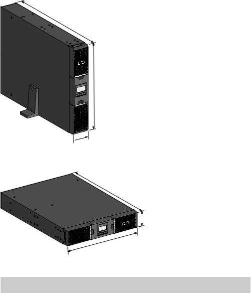
2.1Standard installations
Tower installation
D
W
 H
H
Rack installation
D
 H
H
W
Description |
Weights |
Dimensions (mm/inch) |
|
(kg/lb) |
D x W x H |
9PX1000IRT2U |
17.4 / 38.4 |
450 x 440 x 86.5 / 17.7 x 17.3 x 3.4 |
|
|
|
9PX1500IRT2U |
18.9 / 41.7 |
450 x 440 x 86.5 / 17.7 x 17.3 x 3.4 |
|
|
|
9PX1500IRTM |
18.9 / 41.7 |
450 x 440 x 86.5 / 17.7 x 17.3 x 3.4 |
|
|
|
9PX2200IRT2U |
25 / 55.2 |
605 x 440 x 86.5 / 23.8 x 17.3 x 3.4 |
|
|
|
9PX2200IRT3U |
24.5 / 54.1 |
485 x 440 x 130 / 19.1 x 17.3 x 5.1 |
|
|
|
9PX3000IRT2U |
27.6 / 60.8 |
605 x 440 x 86.5 / 23.8 x 17.3 x 3.4 |
|
|
|
9PX3000IRT3U |
27.4 / 60.4 |
485 x 440 x 130 / 19.1 x 17.3 x 5.1 |
|
|
|
9PX3000IRTM |
27.4 / 60.4 |
485 x 440 x 130 / 19.1 x 17.3 x 5.1 |
|
|
|
9PXEBM48RT2U |
29.8 / 65.7 |
450 x 440 x 86.5 / 17.7 x 17.3 x 3.4 |
|
|
|
9PXEBM72RT2U |
39.2 / 86.4 |
605 x 440 x 86.5 / 23.8 x 17.3 x 3.4 |
|
|
|
9PXEBM72RT3U |
38.2 / 84.2 |
485 x 440 x 130 / 19.1 x 17.3 x 5.1 |
|
|
|
Page 8 |
9PX 1-3 KVA EU_EN |

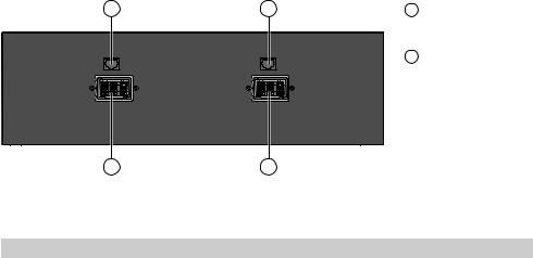
2.2Rear panels
9PX 1000IRT & 9PX 1500IRT
9PX 2200IRT & 9PX 3000IRT (2U)
|
|
|
|
|
|
|
|
|
|
|
|
2. Presentation |
ENGLISH |
|
|
|
|
|
|
|
|
|
|
|
|
|
|
|
|
|
|
|
|
|
|
|
|
1 |
Socket for connection to AC power |
|
|
|
|
|
|
|
|
|
|
|
|
|
|||
|
|
|
|
|
|
|
|
|
|
|
|
source |
|
|
|
|
|
|
|
|
|
|
|
2 |
Slot for optional communication card |
|
|
|
|
|
|
|
|
|
|
|
|
|
3 |
Relay output contact |
|
|
|
|
|
|
|
|
|
|
|
|
|
||
|
|
|
|
|
|
|
|
|
|
|
|
||
|
|
|
|
|
|
|
|
|
|
4 |
Connector for additional battery |
|
|
|
|
|
|
|
|
|
|
|
|
|
|
module |
|
|
|
|
|
|
|
|
|
|
|
|
|
|
|
|
|
|
|
|
|
|
|
|
|
5 |
Primary group: outlets for |
|
|
|
|
|
|
|
|
|
|
|
|
|
|
connection of critical equipment |
|
|
|
|
|
|
|
|
|
|
|
6 |
Group 1: programmable |
|
|
|
|
|
|
|
|
|
|
|
|
|
|
outlets for connection of equipment |
|
|
|
|
|
|
|
|
|
|
|
7 |
Group 2: programmable |
|
|
|
|
|
|
|
|
|
|
|
|
|
|
outlets for connection of equipment |
|
|
|
|
|
|
|
|
|
|
|
8 |
Connector for automatic recognition |
|
|
|
|
|
|
|
|
|
|
|
|
|
|
of an additional battery module |
|
|
|
|
|
|
|
|
|
|
|
9 |
RS232 communication port |
|
|
|
|
|
|
|
|
|
|
|
|
|
|||
10USB communication port
11Connector for ROO (Remote On/Off) control and RPO (Remote Power Off)
9PX 2200IRT & 9PX 3000IRT (3U)
9PX EBM 48V
|
12 |
Connectors for battery modules |
13 |
13 |
(to the UPS or to the other battery |
|
|
modules) |
|
13 |
Connectors for automatic recognition |
|
|
of battery modules |
12 |
12 |
9PX EBM 72V (2U)
13 |
13 |
12 |
12 |
9PX 1-3 KVA EU_EN |
Page 9 |
2. Presentation
9PX EBM 72V (3U)
13 |
13 |
12 |
Connectors for battery modules |
|
|
|
(to the UPS or to the other battery |
|
|
|
modules) |
|
|
13 |
Connectors for automatic recognition |
|
|
|
of battery modules |
12 |
12 |
|
2.3 Accessories |
|
|
|
|
|
|
Part number |
Description |
|
9PXEBM48RT2U |
|
|
9PXEBM72RT2U |
Extended battery module |
|
9PXEBM72RT3U |
|
|
Network-MS |
Network card |
|
|
|
|
Modbus-MS |
Modbus and network card |
|
|
|
|
Relay-MS |
Relay card |
|
|
|
|
BINTSYS |
Battery Integration System |
|
|
|
|
EBMCBL48 |
2m cable 48V EBM |
|
EBMCBL72 |
2m cable 72V EBM |
|
|
|
|
MBP3KI |
|
|
MBP3KIF |
|
|
MBP3KID |
Maintenance Bypass |
|
MBP3KIH |
|
|
MBP3KIB |
|
Page 10 |
9PX 1-3 KVA EU_EN |
2. Presentation
2.4Control panel
The UPS has a five-button graphical LCD. It provides useful information about the UPS itself, load status, events, measurements and settings.
Online mode |
Fault |
indicator (green) |
indicator (red) |
Battery mode |
Bypass mode |
indicator (orange) |
indicator (orange) |
ENGLISH
Online mode |
|
100% |
100% |
2.7kW |
19min |
3.0kVA |
1EBM |
Efficiency: 94 % |
|
Escape |
Up |
Down |
Enter |
On/Off |
|
|
|
|
button |
The following table shows the indicator status and description:
Indicator |
Status |
Description |
|||
|
|
|
On |
The UPS is operating normally on Online or on High |
|
Green |
Efficiency mode. |
||||
|
|||||
|
|
|
On |
The UPS is on Battery mode. |
|
|
|
|
|||
Orange |
|||||
|
|
||||
Orange |
On |
The UPS is on Bypass mode. |
|||
|
|
||||
|
|
|
On |
The UPS has an active alarm or fault. See trouble- |
|
Red |
shooting on page 35 for additional information. |
||||
|
|||||
|
|
||||
9PX 1-3 KVA EU_EN |
Page 11 |
2. Presentation
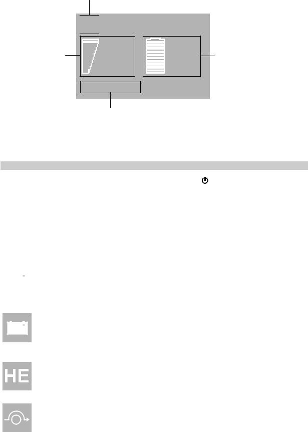
2.5LCD description
After 5 minutes of inactivity, the LCD displays the screen saver.
The LCD backlight automatically dims after 10 minutes of inactivity. Press any button to restore the screen.
Operation status


 Online mode
Load/equipment status
|
|
|
|
|
|
|
|
|
100% |
100% |
|
|
|
|
|
|
|
|
|
||
|
|
|
|
|
|
|
|
|
||
|
|
|
|
|
|
|
|
|
2.7kW |
19min |
|
|
|
|
|
|
|
|
|
||
|
|
|
|
|
|
|
|
|
||
|
|
|
|
|
|
|
|
|
3.0kVA |
1EBM |
|
|
|
|
|
|
|
|
|
||
|
|
|
|
|
|
|
|
|
||
|
|
|
|
|
|
|
|
|
||
|
|
|
|
|
|
|
|
|
|
|
|
|
|
|
|
|
|
|
|
|
|
Efficiency: 94%
Battery status
Efficiency and load group information
The following table describes the status information provided by the UPS
Note: If other indicator appears, see troubleshooting on page 35 for additional information.
Operation status |
Cause |
Description |
||||||
Standby mode |
The UPS is Off, waiting form start- |
Equipment is not powered until |
||||||
|
|
|
|
|
|
|
up command from user. |
button is pressed. |
|
|
|
|
|
|
|
||
|
|
|
|
|
|
|
|
|
|
|
|
|
|
|
|
|
|
Online mode |
The UPS is operating normally. |
The UPS is powering and protecting |
||||||
|
|
|
|
|
|
|
|
the equipment. |
|
|
|
|
|
|
|
|
|
|
|
|
|
|
|
|
|
|
|
|
|
|
|
|
|
|
|
|
Battery mode |
A utility failure has occured and |
The UPS is powering the equipment |
|||||
|
|
|
|
|
|
|
the UPS is on Battery mode. |
with the battery power. |
|
|
|
|
|
|
|
||
|
|
|
|
|
|
|
|
Prepare your equipment for shut- |
|
|
|
|
|
|
|
|
down. |
|
|
|
|
|
|
|
|
|
1 beep every 10 seconds |
|
|
||||||
End of backup time |
The UPS is on Battery mode and |
This warning is approximate, and |
||||||
|
|
|
|
|
|
|
the battery is running low. |
the actual time to shutdown may |
|
|
|
|
|
|
|
|
vary significantly. |
1 beep every 3 seconds |
|
|
||||||
High Efficiency mode |
The UPS is operating on High |
The UPS is powering and protecting |
||||||
|
|
|
|
|
|
|
Efficiency mode. |
the equipment. |
|
|
|
|
|
|
|
|
|
|
Bypass mode |
An overload or a fault has occurred, |
Equipment is powered but not |
|||||
|
|
|
|
|
|
|
or a command has been received, |
protected by the UPS. |
|
|
|
|
|
|
|
and the UPS is on Bypass mode. |
|
|
|
|
|
|
|
|
|
|
Page 12 |
9PX 1-3 KVA EU_EN |
 Loading...