

Page 1

Emergency Care · OR/Anesthesia · Critical Care · Perinatal Care · Home Care
Because you care
Atemluftkompressor
Gebrauchsanweisung, Seite 2
Medical Air Compressor
Instructions for Use, Page 2
Compresseur d'air médical
Notice d'utilisation, Page 26
Compresor de aire
Instrucciones de uso, Página 26
Ademluchtcompressor
Gebruiksaanwijzing, Página 50
Compressore di aria respiratoria
Istruzioni per l'uso, Página 50
Andningsluftkompressor
Bruksanvisning, Sida 74
Компрессор дыхательного
воздуха
Руководство по эксплуатации,
стр.74
Kompresor powietrza
medycznego
Instrukcja obsługi, strona 98
Compressor de ar respiratório
Manual de instruções, Página 98
呼吸气体空压机
使用说明书 , 页 122
医療用空気圧縮機
取扱説明書 , 122 ページ
Medikal Hava Kompresörü
Kullanma Kılavuzu, Sayfa 146
Page 2

Inhaltsverzeichnis
2
Contents
Inhaltsverzeichnis
Zu Ihrer und Ihrer Patienten Sicherheit . . . . . . . . . . . . . . . . . 3
Hinweise zum sicheren Gebrauch . . . . . . . . . . . . . . . . . . . . . . 4
Zweckbestimmung . . . . . . . . . . . . . . . . . . . . . . . . . . . . . . . . . . 5
Vorbereiten . . . . . . . . . . . . . . . . . . . . . . . . . . . . . . . . . . . . . . . . . 5
Vor der ersten Inbetriebnahme . . . . . . . . . . . . . . . . . . . . . . . . . 5
Auf das Evita Mobil-Fahrgestell montieren . . . . . . . . . . . . . . . . 6
Auf den separaten Fahrgestellfuß montieren . . . . . . . . . . . . . 9
Kompressor anschließen . . . . . . . . . . . . . . . . . . . . . . . . . . . . . . 9
Für Standby-Funktion . . . . . . . . . . . . . . . . . . . . . . . . . . . . . . . 10
Betrieb . . . . . . . . . . . . . . . . . . . . . . . . . . . . . . . . . . . . . . . . . . . . 11
Standby-Funktion . . . . . . . . . . . . . . . . . . . . . . . . . . . . . . . . . . . 11
Betriebsende . . . . . . . . . . . . . . . . . . . . . . . . . . . . . . . . . . . . . . 11
Pflege . . . . . . . . . . . . . . . . . . . . . . . . . . . . . . . . . . . . . . . . . . . . . 12
Instandhaltungsintervalle . . . . . . . . . . . . . . . . . . . . . . . . . . . . 13
Filtergruppe ausbauen . . . . . . . . . . . . . . . . . . . . . . . . . . . . . . 13
Vorfilter wechseln . . . . . . . . . . . . . . . . . . . . . . . . . . . . . . . . . . 14
Hauptfilter wechseln . . . . . . . . . . . . . . . . . . . . . . . . . . . . . . . . 14
Ansaugfilter wechseln . . . . . . . . . . . . . . . . . . . . . . . . . . . . . . . 16
Filtergruppe einbauen . . . . . . . . . . . . . . . . . . . . . . . . . . . . . . . 17
Sicherungen wechseln . . . . . . . . . . . . . . . . . . . . . . . . . . . . . . 17
Fehler - Ursache - Abhilfe . . . . . . . . . . . . . . . . . . . . . . . . . . . . 18
Was ist was . . . . . . . . . . . . . . . . . . . . . . . . . . . . . . . . . . . . . . . 20
Technische Daten . . . . . . . . . . . . . . . . . . . . . . . . . . . . . . . . . . 21
Funktionsbeschreibung . . . . . . . . . . . . . . . . . . . . . . . . . . . . 23
Bestell-Liste . . . . . . . . . . . . . . . . . . . . . . . . . . . . . . . . . . . . . . . 25
Contents
For Your Safety and that of your Patients . . . . . . . . . . . . . . . 3
Safety instructions . . . . . . . . . . . . . . . . . . . . . . . . . . . . . . . . . . . . 4
Intended Use . . . . . . . . . . . . . . . . . . . . . . . . . . . . . . . . . . . . . . . . 5
Preparing for use . . . . . . . . . . . . . . . . . . . . . . . . . . . . . . . . . . . . 5
Before first use . . . . . . . . . . . . . . . . . . . . . . . . . . . . . . . . . . . . . . . 5
Installing the compressor on the Evita trolley . . . . . . . . . . . . . 6
Installing the compressor on a seperate trolley . . . . . . . . . . . . 9
Connecting the compressor . . . . . . . . . . . . . . . . . . . . . . . . . . . . 9
Standby mode . . . . . . . . . . . . . . . . . . . . . . . . . . . . . . . . . . . . . 10
Operation . . . . . . . . . . . . . . . . . . . . . . . . . . . . . . . . . . . . . . . . . . 11
Standby mode . . . . . . . . . . . . . . . . . . . . . . . . . . . . . . . . . . . . . 11
Switching off . . . . . . . . . . . . . . . . . . . . . . . . . . . . . . . . . . . . . . . 11
Routine maintenance . . . . . . . . . . . . . . . . . . . . . . . . . . . . . . . 12
Maintenance intervals . . . . . . . . . . . . . . . . . . . . . . . . . . . . . . . 13
Removing the filter group . . . . . . . . . . . . . . . . . . . . . . . . . . . . 13
Changing the prefilter . . . . . . . . . . . . . . . . . . . . . . . . . . . . . . . 14
Changing the main filter . . . . . . . . . . . . . . . . . . . . . . . . . . . . . 14
Changing the intake filter . . . . . . . . . . . . . . . . . . . . . . . . . . . . 16
Installing the filter group . . . . . . . . . . . . . . . . . . . . . . . . . . . . . 17
Replacing the fuses . . . . . . . . . . . . . . . . . . . . . . . . . . . . . . . . . 17
Fault - Cause - Remedy . . . . . . . . . . . . . . . . . . . . . . . . . . . . . . 19
What's what . . . . . . . . . . . . . . . . . . . . . . . . . . . . . . . . . . . . . . . 20
Technical Data . . . . . . . . . . . . . . . . . . . . . . . . . . . . . . . . . . . . . 21
Functional description . . . . . . . . . . . . . . . . . . . . . . . . . . . . . 23
Order List . . . . . . . . . . . . . . . . . . . . . . . . . . . . . . . . . . . . . . . . . 25
Page 3

3
Zu Ihrer und Ihrer Patienten SicherheitFor Your Safety and that of your Patients
Zu Ihrer und Ihrer Patienten
Sicherheit
Gebrauchsanweisung beachten
Jede Handhabung an dem Gerät setzt die genaue Kenntnis
und Beachtung dieser Gebrauchsanweisung voraus. Das
Gerät ist nur für die beschriebene Verwendung bestimmt.
Instandhaltung
Das Gerät muss alle 6000 Betriebsstunden, jedoch mindestens einmal jährlich, Inspektionen und Wartungen durch
Fachleute unterzogen werden (mit Protokoll).
Instandsetzungen am Gerät nur durch Fachleute. Für den
Abschluss eines Service-Vertrags sowie für Instandsetzungen
empfehlen wir den DrägerService.
Bei Instandhaltung nur Original-Dräger-Teile verwenden.
Kapitel "Instandhaltungsintervalle" beachten.
Zubehör
Nur das in der Bestell-Liste aufgeführte Zubehör verwenden.
Haftung für Funktion bzw. Schäden
Die Haftung für die Funktion des Gerätes geht in jedem Fall
auf den Eigentümer oder Betreiber über, soweit das Gerät von
Personen, die nicht dem DrägerService angehören, unsachgemäß gewartet oder instandgesetzt wird oder wenn eine Handhabung erfolgt, die nicht der bestimmungsgemäßen
Verwendung entspricht.
Für Schäden, die durch die Nichtbeachtung der vorstehenden
Hinweise eintreten, haftet Dräger nicht. Gewährleistungs- und
Haftungsbedingungen der Verkaufs- und Lieferbedingungen
von Dräger werden durch vorstehende Hinweise nicht
erweitert.
Dräger Medical AG & Co. KG
For Your Safety and that of your
Patients
Strictly follow the Instructions for Use
Any use of the apparatus requires full understanding and strict
observation of these instructions. The apparatus may only be
used for the purposes specified here.
Maintenance
The apparatus must be inspected and serviced (and a record
kept) by trained service personnel after every 6000 hours of
operation or at least once per year.
Repair and general overhaul of the apparatus may only be
carried out by trained service personnel. We recommend that
a service contract be obtained with DrägerService and that all
repairs also be carried out by them.
Only authentic Dräger spare parts may be used for maintenance. Observe the chapter "Maintenance intervals".
Accessories
Only the accessories specified in the Order List may be used
with the apparatus.
Liability for proper function or damage
Liability for the proper function of the apparatus is irrevocably
transferred to the owner or operator to the extent that the apparatus has been improperly serviced or repaired by personnel
not employed or authorized by DrägerService or if it has been
used in a manner not conforming to its intended use.
Dräger cannot be held responsible for damage caused by noncompliance with the recommendations given above. The warranty and liability provisions of the terms of sale and delivery of
Dräger are likewise not modified by the recommendations
given above.
Dräger Medical AG & Co. KG
Page 4

4
Zu Ihrer und Ihrer Patienten Sicherheit For Your Safety and that of your Patients
Hinweise zum sicheren Gebrauch
Kein Betrieb in explosionsgefährdeten Bereichen
Das Gerät ist nicht für den Betrieb in explosionsgefährdeten
Bereichen zugelassen.
Gefahrlose Kopplung mit elektrischen Geräten
Elektrische Kopplung mit Geräten, die nicht in dieser
Gebrauchsanweisung erwähnt sind, nur nach Rückfrage bei
den Herstellern oder einem Sachverständigen.
Versorgung von lebenserhaltenden Beatmungsgeräten
Wird der Kompressor zur Versorgung von lebenserhaltenden
Beatmungsgeräten eingesetzt, so ist für den Fall eines Defekts
am Kompressor eine ausreichende Druckluft-Ersatz-Versorgung sicherzustellen!
Lebenserhaltende Beatmungsgeräte, die vom Kompressor versorgt werden, müssen über eine Alarmfunktion für zu geringen
Versorgungsdruck verfügen!
Medizinische elektrische Geräte unterliegen besonderen
Vorsichtsmaßnahmen hinsichtlich der elektromagnetischen
Verträglichkeit (EMV) und müssen gemäß der in der technischen Dokumentation bereitgestellten EMV Informationen
installiert und in Betrieb genommen werden, die auf Anfrage
vom DrägerService erhältlich ist.
Tragbare und mobile HF Kommunikationseinrichtungen können medizinische elektrische Geräte beeinflussen.
Stifte von Steckern, die mit dem ESD-Warnschild
versehen sind, dürfen nicht berührt oder Verbindungen zwischen diesen Steckern hergestellt
werden, ohne ESD-Schutzmaßnahmen anzuwen-
den. Solche Maßnahmen können antistatische
Kleidung und Schuhe, die Berührung eines Erdungsbolzens
vor und während des Verbindens oder die Benutzung elektrisch isolierender und antistatischer Handschuhe sein.
Betroffenes Personal sollte hinsichtlich dieser ESD Schutzmaßnahmen geschult werden.
Nicht in Gegenwart entflammbarer Gase oder Narkosemittel benutzen, Brandgefahr!
Keine brennbaren Flüssigkeiten in der Nähe des Kompressors versprühen, Brandgefahr!
Schadstoffe in der Raumluft vermeiden!
Der Kompressor saugt Raumluft an. Schadstoffe würden
zum Patienten gelangen.
Allgemeine Informationen zur elektromagnetischen
Verträglichkeit (EMV) gemäß internationalem
EMV Standard IEC 60601-1-2: 2001
Safety instructions
Not for use in areas of explosion hazard
This apparatus is neither approved nor certified for use in
areas where combustible or explosive gas mixtures are likely to
occur.
Safe connection with other electrical equipment
Electrical connections to equipment which are not listed in
these Instructions for Use should only be made following consultations with the respective manufacturers or an expert.
Supplying life-supporting ventilators
If the compressor is used to supply air to life-support ventilators, an adequate alternative supply of medical air must be
ensured in case a fault develops in the compressor!
Where the Compressor is used to supply air to life support
ventilators, the ventilator should monitor the supply pressure
and appropriately alarm if necessary.
Medical electrical equipment needs special precautions
regarding electromagnetic compatibility (EMC) and needs to
be installed and put into service according to the EMC information provided in the technical documentation available from
DrägerService upon request.
Portable and mobile RF communications equipment can affect
medical electrical equipment.
Pins of connectors identified with the
ESD warning symbol shall not be touched and not
be connected unless ESD precautionary procedures are used. Such precautionary procedures
may include antistatic clothing and shoes, the
touch of a ground stud before and during connecting the pins
or the use of electrically isolating and antistatic gloves. All staff
involved in the above shall receive instruction in these procedures.
Must not be used in the presence of flammable gases or
anaesthetics. Fire hazard!
Inflammable liquids must not be sprayed near the compressor. Fire hazard!
Prevent pollution of room air!
The compressor draws in air from the room. Any pollutants in
the air would reach the patient.
General information on electromagentic compatibility
(EMC) according to the international EMC standard IEC
60601-1-2: 2001
Page 5

5
Vorbereiten Preparing for use
Zweckbestimmung
Atemluftkompressor zur Versorgung
eines Beatmungsgerätes mit medizinischer Druckluft.
Vorbereiten
Vor der ersten Inbetriebnahme
Der Kompressor wird ohne Fahrgestell
angeliefert. Er kann auf das Evita MobilFahrgestell montiert werden oder auf
den separaten Fahrgestellfuß.
Montage nur durch Fachleute.
Benötigte Werkzeuge:
Schlüssel für Innensechskantschraube
SW 5,
Kreuzschlitzschraubendreher, Größe 2,
Gabelschlüssel SW 19.
Atemluftkompressor erst nach der
Montage in das Fahrgestell betreiben.
Sonst kann das Kompressoraggregat
mangels Luftzirkulation beschädigt
werden!
Intended Use
Air compressor supplying compressed
air for medical ventilators.
Preparing for use
Before first use
The compressor is supplied without trolley. It can be installed on the Evita trolley
or on a separate trolley.
The compressor may only be installed by
trained service personnel.
Tools required:
Spanner for size 5 Allen screw,
Phillips screwdriver, size 2,
Size 19 fork wrench.
The medical air compressor must
not be started up until it has been
installed on the trolley.
The compressor unit may be damaged
as a result of poor air circulation if this
is not done!
Page 6
Vorbereiten
6
Preparing for use
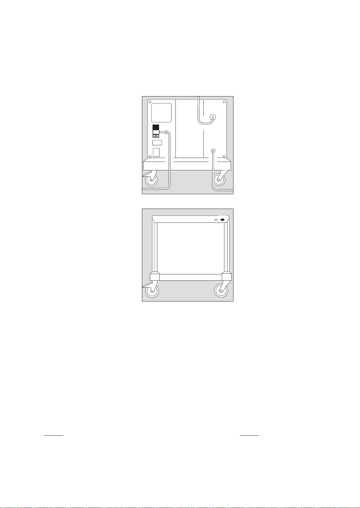
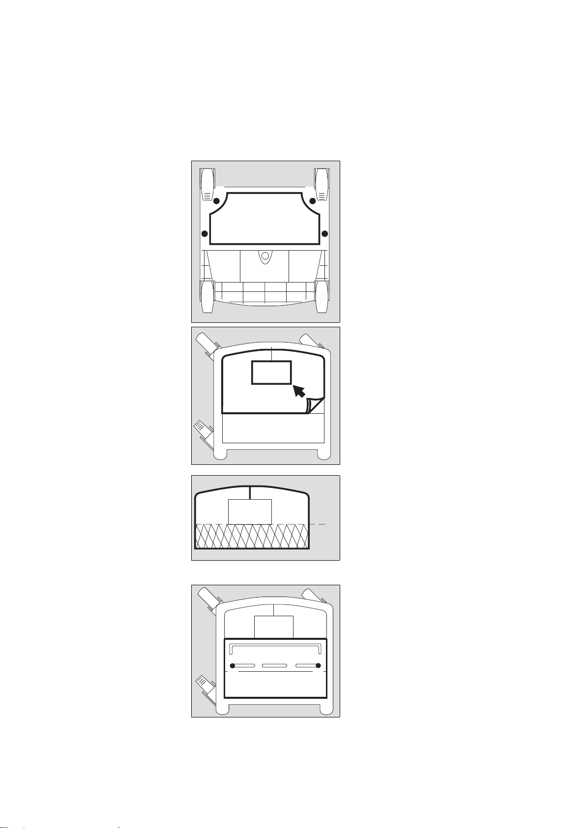
Auf das Evita Mobil-Fahrgestell
montieren
● Beatmungsgerät vom Evita Mobil-
Fahrgestell abnehmen.
● Evita Mobil-Fahrgestell auf den
Boden legen, dass die Unterseite
zugänglich ist.
1 Abluftkappe mit beiliegenden Kreuz-
schlitzschrauben unter den Rahmen
des Fahrgestells schrauben.
● Fahrgestell wieder auf die Rollen stel-
len.
2 Schaumstoffmatte aus dem Fahrge-
stell herausnehmen.
● Schaumstoffmatte an der vorbereite-
ten Schnittstelle abschneiden.
3 Die beiden Teile wieder in das Fahr-
gestell einlegen.
4 Die beiden Schrauben der Batterie-
abdeckung herausschrauben, Batterieabdeckung herausnehmen.
● Die beiden Schrauben unter der Bat-
terieabdeckung heraus-schrauben.
01429080
11
1
1
01529080
2
01629080
✂
33
01729080
44
Installing the compressor on
the Evita trolley
● Remove the ventilator from the Evita
trolley.
● Lay the Evita trolley on the ground so
that the underside is accessible.
1 Secure the exhaust air cover to the
trolley frame with the enclosed Phillips screws.
● Turn the trolley upright again.
2 Remove the foam mat from the
trolley.
● Cut the foam mat off along the pre-
pared line.
3 Place both parts in the trolley.
4 Undo the two screws on the battery
compartment cover and remove the
cover.
● Undo the two screws below the bat-
tery compartment cover.
Page 7
7
Vorbereiten Preparing for use
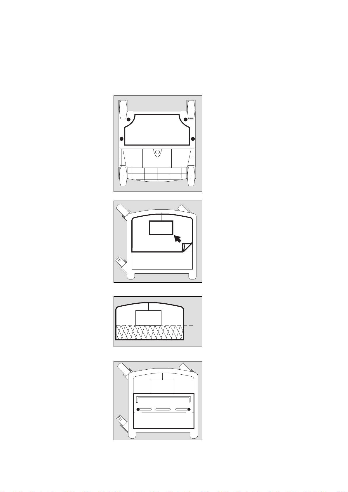
Am Kompressor:
1 Die vier Innensechskantschrauben
auf der Rückseite herausschrauben.
2 Die Haube vorsichtig nur ca. 10 cm
zurückziehen, dass das Kabel der
Anzeigelampe nicht abgerissen wird.
3 Kreuzschlitzschraube am Stecker
herausschrauben, Stecker ziehen,
Haube ganz abziehen.
4 Kompressor auf das Fahrgestell
stellen, Druckbehälter neben der
Säule platziert.
5 Kompressor mit den vier Innensechs-
kantschrauben und Unterlegscheiben am Fahrgestell festschrauben.
Sicherstellen, dass Netzstecker
gezogen, sonst Gefahr eines elektrischen Schlags!
00129080
1
1
1
1
00229080
2
ca. 10 cm/approx. 10 cm
01829080
3
00529080
5
5
4
55
On the compressor:
1 Undo the four Allen screws on the
rear of the compressor.
2 Carefully draw the shroud back
approx. 10 cm so that the indicator
lead is not pulled off.
3 Undo the Phillips screw on the plug
connector, unplug the connector and
remove the shroud completely.
4 Place the compressor on the trolley
with the pressure vessel alongside
the column.
5 Tightly secure the compressor to the
trolley with the four Allen screws and
washers.
Ensure that the mains power cable
has been unplugged in order to
avoid electric shocks!
Page 8
Vorbereiten
8
Preparing for use
1 Die vier Innensechskantschrauben
der Transportsicherung herausschrauben.
2 Die beiden Laschen der Transport-
sicherung herausziehen.
3 Den Motorstecker stecken und mit
der Kreuzschlitzschraube sichern.
Laschen und Schrauben der Transportsicherung für spätere Transporte
aufbewahren.
● Haube aufsetzen, deren Stecker
stecken und mit der Kreuzschlitzschraube sichern.
● Haube zuschieben und die vier
Innensechskantschrauben auf der
Rückseite hineinschrauben.
Vor jeder Erstinbetriebnahme
Transportsicherung abnehmen,
sonst entstehen starke Vibrationen
am Atemluftkompressor.
Das Kompressoraggregat kann
beschädigt werden!
Vor jedem Transport, der abweicht
vom betriebsgemäßen Transport im
Fahrgestell:
Transportsicherung einbauen, sonst
können die Gummifüße beschädigt
werden.
01929080
1
1
1
1
02029080
3
2 2
1 Undo the four Allen screws securing
the internal packing.
2 Pull out the two tabs on the internal
packing.
3 Plug in the motor connector and
secure it with the Phillips screw.
Keep the tabs and screws from the
internal packing for future use.
● Fit the shroud, plug in its connector
and secure it with the Phillips screw.
● Close the shroud and screw down
the four Allen screws on the rear of
the unit.
This safety mechanism must always
be removed before using the compressor for the first time, otherwise
major vibrations may develop in the
compressor.
These may damage the compressor
unit!
The internal packing must be fitted
whenever the compressor is transported without its trolley, otherwise
the rubber feet may be damaged.
Page 9
9
Vorbereiten Preparing for use
Auf den separaten
Fahrgestellfuß montieren
Montage des Kompressors wie für Evita
Mobil-Fahrgestell durchführen.
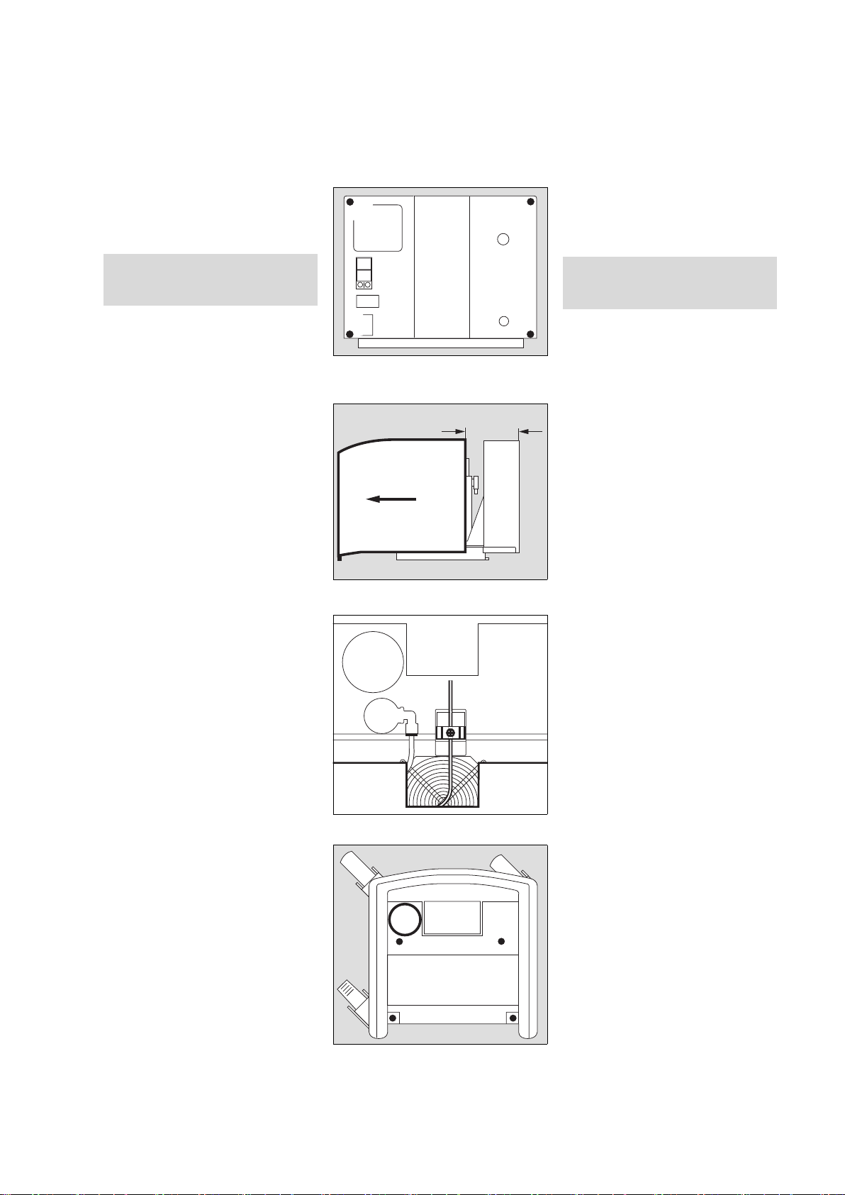
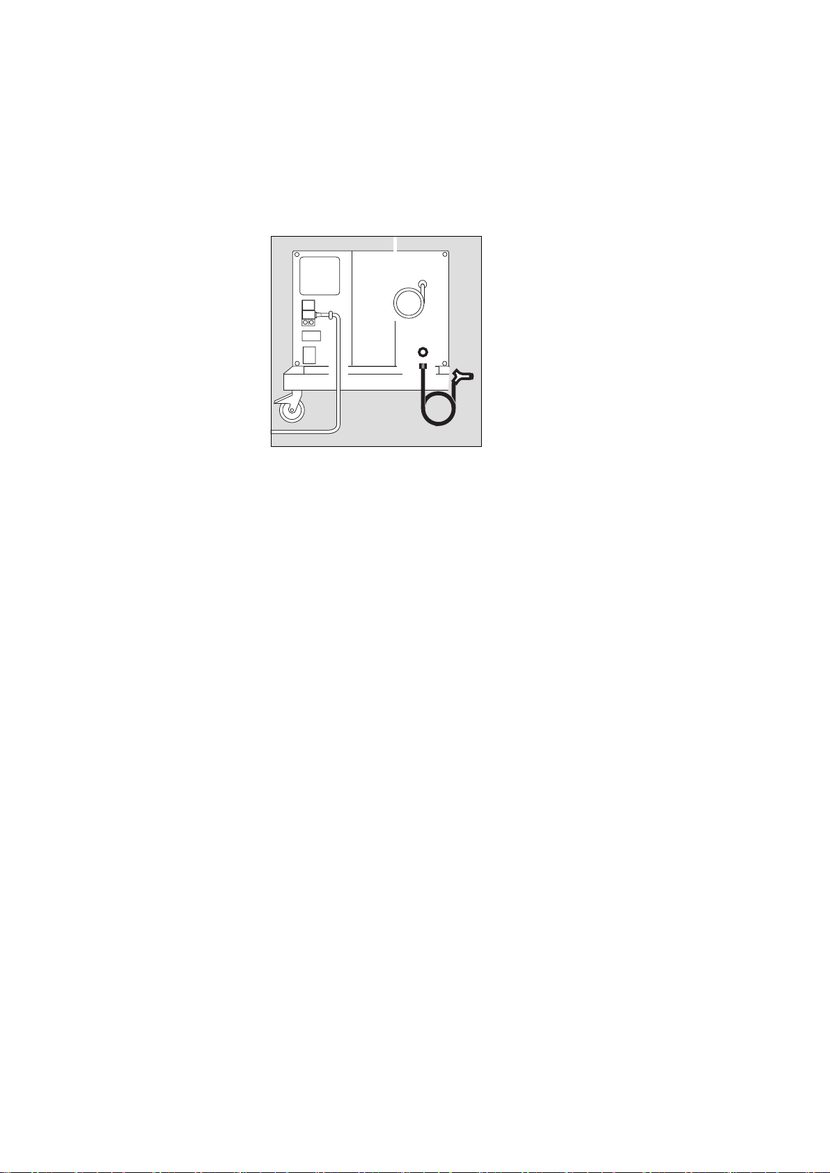
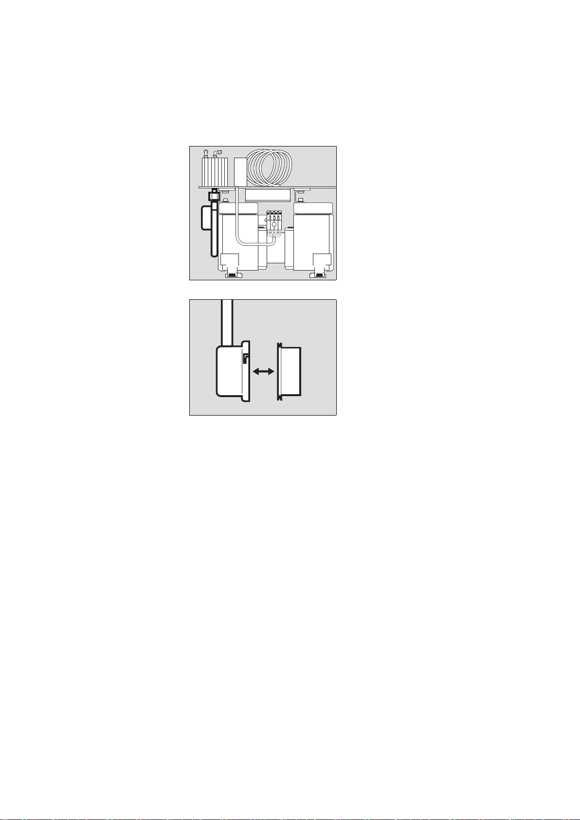
Kompressor anschließen
1 Sicherstellen, dass die Betriebsspan-
nung am Typenschild auf der Rückseite mit der Netzspannung
übereinstimmt.
2 Schelle abschrauben.
3 Gerätestecker stecken, Kabel straf-
fen, unter die Schelle klemmen
und
2 Schelle festschrauben.
4 Netzstecker in eine geerdete Steck-
dose stecken, keinen Adapterstecker
benutzen.
5 Druckluft-Anschlussschlauch am
Beatmungsgerät anschrauben.
6 Stecker des Druckluft-
Anschlussschlauchs fest in die Kupplung des Kompressors stecken – bis
zum Einrasten.
● Kompressor an möglichst kühlem Ort
platzieren, nicht vor Heizungen oder
anderen Wärmequellen.
Für eine ungehinderte Luftzirkulation
um den Kompressor herum sorgen.
● Kompressor nicht in salzhaltiger Luft
betreiben, die Rückschlagventile im
Kompressor können korrodieren.
Nicht mehrere Beatmungsgeräte am
Kompressor anschließen!
Der Kompressor kann überlastet
werden.
02129080
5
6
4
1
2
3
Installing the compressor on a
seperate trolley
The compressor is installed in the same
way as on the Evita trolley.
Connecting the compressor
1 Check that the operating voltage
specified on the rating plate matches
the mains voltage.
2 Unscrew clamp.
3 Plug in apparatus connector, pull
cable until taut, secure under clamp
and
2 screw clamp back into place.
4 Plug the connector into an earthed
socket; do not use an adapter.
5 Screw the pressure hose onto the
ventilator.
6 Firmly insert the connector on the
pressure hose into the coupling on
the compressor – until it engages.
● Place the compressor in a cool place,
away from radiators and other
sources of heat.
Ensure that air can circulate freely
around the compressor.
● The compressor must not be oper-
ated in salty air, as this may cause the
non-return valves in the compressor
to corrode.
Do not connect more than one ventilator to the compressor!
It could overload the compressor.
Page 10
Vorbereiten
10
Preparing for use
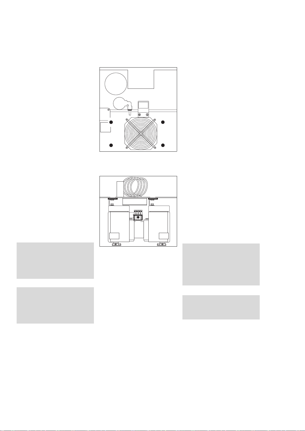
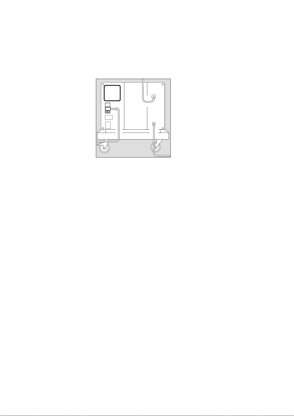
Für Standby-Funktion
(Option)
Zur Versorgung des Beatmungsgerätes
bei Ausfall des zentralen Druckluftsystems.
1 Druckluft-Anschlussschlauch am
Kompressor anschrauben.
2 Stecker in die Wandentnahmestelle
des zentralen Druckluftsystems
stecken.
02229080
2
1
Standby mode
(optional)
For emergency supply if the central medical air system fails.
1 Screw the pressure hose to the com-
pressor.
2 Plug the connector into the wall
socket of the central medical air system.
Page 11
11
Betrieb Operation
Betrieb
Wurde der Kompressor bei Temperaturen unter 3 °C gelagert:
● Ca. 2 Stunden für Temperaturaus-
gleich abwarten.
1 Netzschalter auf der Rückseite
drücken,
2 die grüne Lampe »
N « vorn in der
Haube leuchtet = EIN.
● Das angeschlossene Beatmungsge-
rät einschalten.
Bei Betriebstörungen siehe "Fehler Ursache - Abhilfe", Seite 18.
Standby-Funktion
Zur Versorgung des Beatmungsgerätes
bei Ausfall des zentralen Druckluftsystems.
● Netzschalter immer eingeschaltet
lassen = grüne Lampe » N « vorn in
der Haube leuchtet
Der eingeschaltete Kompressor überwacht den Druck im zentralen Druckluftsystem:
Fällt der Druck unter 2,7
–0,3 bar
1)
, übernimmt der Kompressor automatisch die
Druckluftversorgung des angeschlossenen Beatmungsgerätes. Steigt der
Druck im zentralen Druckluftsystem wieder über 3,4 bar2), schaltet der Kompressor seine Versorgung ab und bleibt
in Standby.
Betriebsende
Nach dem Abschalten des Beatmungsgerätes:
● Netzschalter auf der Rückseite
drücken,
● die grüne Lampe » N « erlischt
= AUS.
Der Kompressor entlüftet sich automatisch.
1)
US-Kompressor 115 V/60 Hz/Standby:
2,7±0,2 bar
2)
US-Kompressor 115 V/60 Hz/Standby:
3,2±0,2 bar
02329080
1
01029080
2
Operation
If the compressor has been stored at
temperatures below 3 °C:
● Wait approx. 2 hours for the com-
pressor to warm up.
1 Press main switch on rear,
2 the green LED »
N « in the front of
the shroud lights up = ON.
● Now switch on the ventilator.
Refer to "Fault - Cause - Remedy" on
page 19 if any faults develop.
Standby mode
For emergency supply if the central medical air system fails.
● Always leave the main switch ON =
green LED » N « on front of shroud
lights up.
The pressure in the central medical air
system is monitored by the compressor
while switched on:
If the pressure drops below
2.7
–0.3 bar
1)
, the compressor automatically supplies medical air to the ventilator to which it is connected. The
compressor switches off the supply and
remains on standby when the pressure
in the central medical air system rises
above 3.4 bar2).
Switching off
After switching off the ventilator:
● Press the main switch on the rear,
● the green LED » N « goes out
= OFF.
The compressor is vented automatically.
1)
US Compressor 115 V/60 Hz/Standby:
2.7±0.2 bar
2)
US Compressor 115 V/60 Hz/Standby:
3.2±0.2 bar
Page 12
Pflege
12
Routine maintenance
Pflege
Wenn die Filtermatte verschmutzt ist:
1 Filtermatte herausnehmen, Schmutz
ausklopfen, Filtermatte wieder
einsetzen.
● Schmutz am Gehäuse des Kompres-
sors mit einem Einwegtuch
entfernen.
Wischdesinfizieren des Gehäuses
Zur Desinfektion Präparate aus der
Gruppe der Flächendesinfektionsmittel
verwenden. Aus Gründen der Materialverträglichkeit eignen sich Präparate auf
der Wirkstoffbasis von:
— Aldehyden,
— quaternären Ammoniumverbinungen.
Wegen möglicher Schädigung der Materialien eignen sich keine Präparate auf
der Basis von:
— Phenol-haltigen Verbindungen,
— Halogen-abspaltenden Verbindun-
gen,
— starken organischen Säuren,
— Sauerstoff-abspaltenden Verbindun-
gen.
● wischdesinfizieren
z.B. mit Incidur
®
(Fa. Ecolab
Deutschland GmbH)
● Anwendungsvorschriften des Her-
stellers beachten.
02429080
1
Routine maintenance
If the filter mat is soiled:
1 Remove the filter mat, knock out any
dirt and insert the mat again.
● Any dirt on the compressor housing
should be wiped off with a disposable cloth.
Wiping with disinfectant
A surface disinfectant can be used to
wipe the housing. Preparations based
on:
—aldehydes or
— quaternary ammonium compounds.
Preparations based on the following
compounds should not be used as they
may damage the housing:
— Compounds containing phenol,
— Compounds giving off halogens,
— Strong organic acids,
— Compounds giving off oxygen.
● Wipe with disinfectant e.g. Incidur
®
(Ecolab Deutschland GmbH)
● Note the manufacturer's instructions.
Page 13
13
Instandhaltungsintervalle Maintenance intervals
Instandhaltungsintervalle
Instandhaltung durch Fachleute
Im Bedarfsfall Instandhaltung in kürzeren Intervallen durchführen.
War das Gerät keine 6000 Stunden in
Betrieb:
● Nach spätestens einem Jahr Inspek-
tion und Wartung durchführen.
Verschmutzte Filter mit dem Hausmüll
entsorgen.
Filtergruppe ausbauen
Gehäuse abnehmen, siehe Seite 7.
1 Beide Kreuzschlitzschrauben heraus-
schrauben.
2 Schläuche abnehmen:
Ring zurückgedrückt halten und
gleichzeitig Schlauch aus dem
Anschluss ziehen.
● Filtergruppe herausnehmen.
spätestens alle 6000
Betriebsstunden:
(siehe Betriebsstundenzähler)
Filterwechsel für
Vorfilter,
Hauptfilter,
Ansaugfilter
Netzstecker ziehen! Sonst Gefahr
eines elektrischen Schlags!
03029080
1
1
02829080
2
2
2
Maintenance intervals
Maintenance work may only be carried
out specially trained service personnel.
Carry out maintenance more frequently
if necessary.
If the apparatus has not been in operation for 6000 hours:
● Carry out inspection and servicing
after not more than a year.
Dispose of used filters with domestic
waste.
Removing the filter group
Remove the housing, see page 7.
1 Undo both Phillips screws.
2 Disconnect the hoses:
Pull back and hold the ring while pulling the hose from the socket at the
same time.
● Remove the filter group.
at least every
6000 hours:
(see operating hours
counter)
Change filters
in prefilter,
main filter and
intake filter
The apparatus must always be
unplugged from the mains in order
to avoid electric shocks!
Page 14
Instandhaltungsintervalle
14
Maintenance intervals
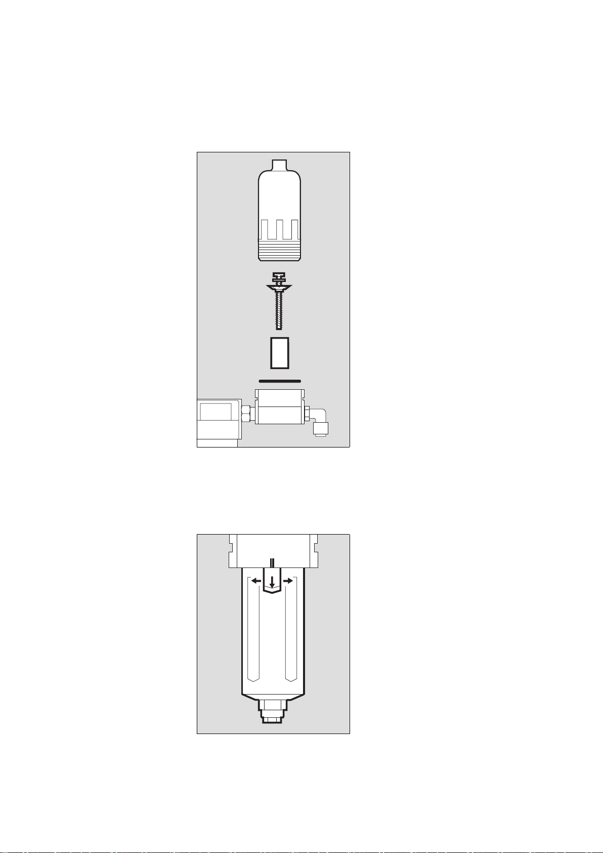
Vorfilter wechseln
1 Gehäuse mit der Hand abschrauben.
2 Kreuzschlitz-Schraube abschrauben
und mit Kunststoffscheibe abneh-
men.
3 Filterhülse herausnehmen und
gegen eine Neue wechseln.
3 Neue Filterhülse einsetzen.
2 Mit Kreuzschlitz-Schraube und Kunst-
stoffscheibe festschrauben.
4 Alten O-Ring herausnehmen, neuen
O-Ring einlegen.
● Gehäuse fest mit der Hand anschrau-
ben.
Hauptfilter wechseln
5 Klinke gezogen halten und
gleichzeitig
6 Gehäuse drehen, bis sich die
Markierungen ( II ) decken.
● Gehäuse abziehen.
03129080
1
2
3
4
02629080
5
66
Changing the prefilter
1 Unscrew the housing by hand.
2 Unscrew recessed head screw and
remove screw and plastic washer.
3 Remove the filter sleeve and replace.
3 Insert the new filter sleeve.
2 Fasten in place with recessed head
screw and plastic washer.
4 Remove old O-ring and fit new O-ring.
● Screw housing together by hand.
Changing the main filter
5 Pull and hold the catch while simulta-
neously
6 turning the housing until the
marks ( II ) line up.
● Remove the housing.
Page 15
15
Instandhaltungsintervalle Maintenance intervals
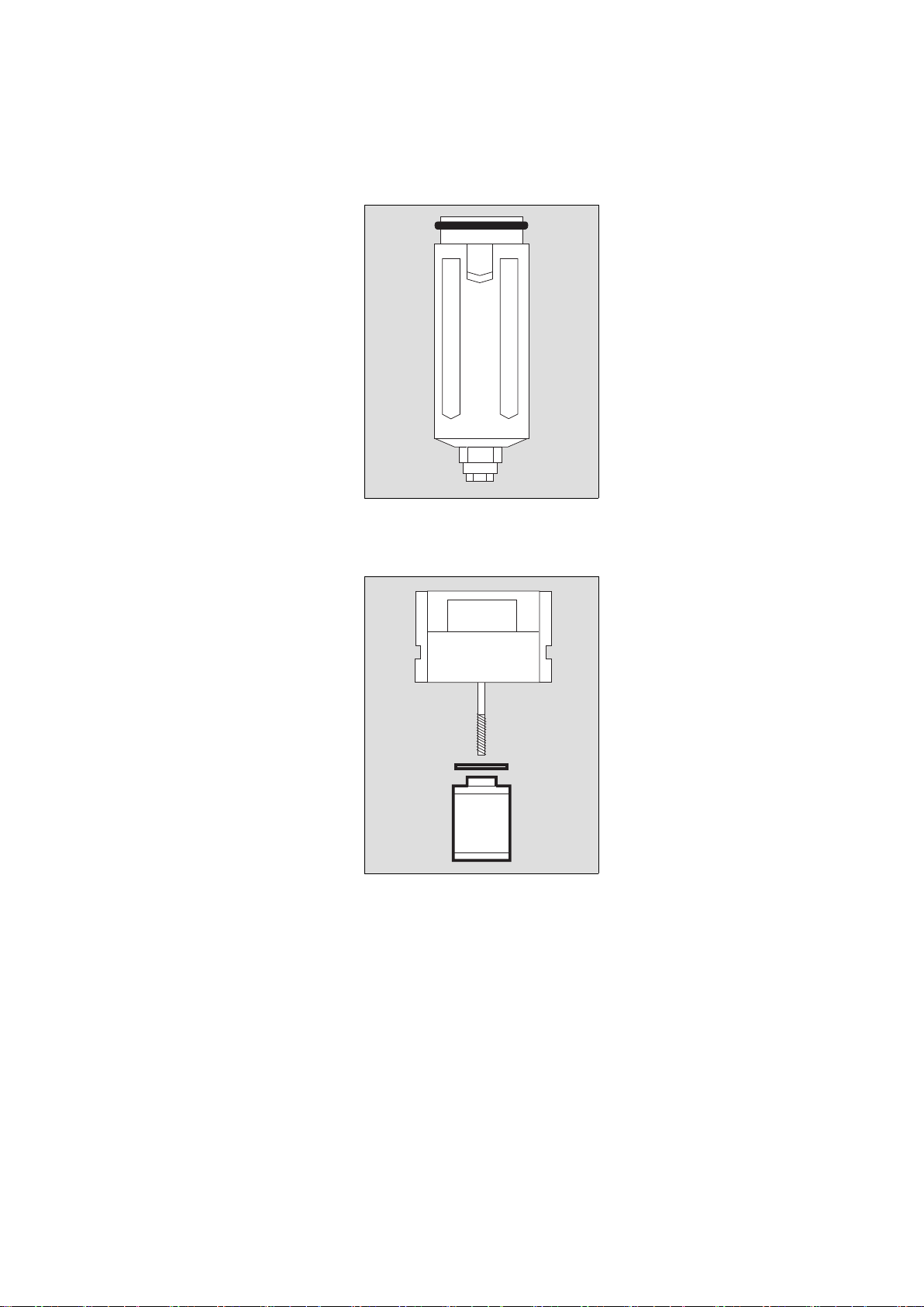
1 Alten O-Ring vom Gehäuse abneh-
men, neuen O-Ring montieren.
2 Alte Filterhülse mit der Hand heraus-
schrauben und neue Filterhülse einschrauben.
● Gehäuse so einsetzen, dass sich die
Markierungen decken und drehen
bis die Klinke hörbar einrastet.
● Mit leichtem Zug am Gehäuse
prüfen, ob das Gehäuse eingerastet
ist.
03729080
1
02729080
2
1 Remove old O-ring from housing and
fit new O-ring.
2 Unscrew old filter sleeve by hand and
screw in new filter sleeve.
● Insert the housing so that the marks
line up, then turn until the catch is
heard to engage.
● Lightly pull the housing to ensure that
it has engaged.
Page 16
Instandhaltungsintervalle
16
Maintenance intervals
Ansaugfilter wechseln
1 Die jeweils zwei Innensechskant-
schrauben an den vorderen und hin-
teren Montageblechen des
Kompressoraggregats heraus-
schrauben.
2 Druckluftschlauch mit Gabel-
schlüssel SW 19 abschrauben, mit
einem zweiten Maulschlüssel das
Verbindungsstück zum Wärme-
tauscher vor Losdrehen sichern.
● Das Kompressoraggregat soweit her-
ausziehen, bis das rückseitige Aus-
gangsrohr des Filtergehäuses nicht
mehr aus der Bohrung ragt.
3 Filtergehäuse im Uhrzeigersinn dre-
hen und abnehmen.
4 Altes Ansaugfilter herausnehmen
und ein Neues ins Filtergehäuse ein-
setzen.
● Filtergehäuse aufsetzen, das Rohr
nach hinten zeigend ca. auf Position
"11 Uhr".
3 Filtergehäuse gegen Uhrzeigersinn
drehen, bis es verriegelt ist. Rohr ist
in horizontaler Position.
● Durch Ziehen den festen Sitz des Fil-
tergehäuses prüfen.
● Kompressoraggregat zurückschie-
ben, dabei das Rohr in die Bohrung
einführen.
2 Druckluftschlauch mit Gabel-
schlüssel SW 19 festschrauben, mit
einem zweiten Maulschlüssel das
Verbindungsstück zum Wärmetau-
scher vor Losdrehen sichern.
1 Kompressoraggregat vorn und hinten
mit jeweils zwei Innensechskant-
schrauben festschrauben.
03329080
3
1
1
2
03229080
4
Changing the intake filter
1 Remove the two Allen screws on the
front of the assembly plates of the
compressor unit and undo the two
rear Allen screws two turns.
2 Unscrew the pressure hose with a
size 19 fork wrench and hold the connector to the heat exchanger with a
second spanner to prevent it working
loose.
● Pull the compressor unit out until the
outlet pipe at the rear of the filter
housing no longer protrudes from the
hole.
3 Turn the filter housing clockwise and
remove it.
4 Remove the old intake filter and
insert a new filter in the filter housing.
● Position the filter housing with the
pipe facing to the rear in a position
corresponding roughly to
"11 o'clock".
3 Turn the filter housing anticlockwise
until locked. The pipe is now horizontal.
● Pull gently to check that the filter
housing is secure.
● Push the compressor unit back, guid-
ing the pipe into the hole at the same
time.
2 Secure the pressure hose with a size
19 fork wrench and hold the connector to the heat exchanger with a second spanner to prevent it working
loose.
1 Secure the compressor unit with the
front and rear Allen screws.
Page 17
17
Instandhaltungsintervalle Maintenance intervals
Filtergruppe einbauen
● Schläuche an der Filtergruppe
anschließen, s. Seite 13.
● Filtergruppe festschrauben,
s. Seite 13.
● Haube aufsetzen, deren elektrischen
Stecker stecken und mit der Kreuzschlitzschraube sichern.
● Haube zuschieben und die vier
Innensechskantschrauben auf der
Rückseite hereinschrauben.
Sicherungen wechseln
● Netzstecker ziehen.
1 Kappen mit Schraubendreher gegen
den Uhrzeigersinn drehen und herausnehmen.
2 Durchgebrannte Sicherungen aus
den Kappen ziehen und neue Sicherungen in die Kappen stecken – Nur
die vorgeschriebenen Sicherungen
verwenden, siehe "Technische
Daten", Seite 21.
1 Kappen mit den neuen Sicherungen
wieder hereindrehen.
Gerät entsorgen
— am Ende der Nutzungsphase.
● Gerät nach Rücksprache mit den
zuständigen Entsorgungsunternehmen der fachgerechten Entsorgung
zuführen. Die geltenden gesetzlichen
Vorschriften beachten!
Dieses Gerät fällt in den Geltungsbereich der EU-Richtlinie 2002/96/EG
(WEEE). Es ist nicht für die Nutzung in
privaten Haushalten registriert, eine Entsorgung über die kommunalen Sammelstellen für Elektroaltgeräte ist nicht
zulässig.
Dräger Medical hat ein Unternehmen
autorisiert, die rechtssichere Entsorgung dieses Gerätes vorzunehmen: Für
nähere Informationen wenden Sie sich
bitte an die für Sie zuständige nationale
Dräger Medical Organisation.
03529080
2
1
Installing the filter group
● Connect the hoses to the filter group,
see page 13.
● Screw the filter group into place, see
page 13.
● Fit the shroud, plug in its connector
and secure it with the Phillips screw.
● Close the shroud and screw down
the four Allen screws on the rear of
the unit.
Replacing the fuses
● Unplug the mains connector.
1 Turn the caps anticlockwise with a
screwdriver and remove them.
2 Remove blown fuses from their caps
and insert new fuses. Only the specified fuses may be used, see "Technical data" on page 21.
1 Screw the caps with the new fuses
back into place.
Disposal of the device
— at the end of its useful life.
● After contacting the competent spe-
cialised waste disposal companies,
send the device to the appropriate
expert disposal facility. Observe all
applicable legal requirements.
This device is subject to EU Directive
2002/96/EC (WEEE). It is not registered for use in private households, and
may not be disposed of at municipal collection points for waste electrical and
electronic equipment.
Dräger Medical has authorized a firm to
dispose of this device in the proper manner: for more detailed information,
please contact your local Dräger Medical organization.
Page 18

Fehler - Ursache - Abhilfe
18
Fehler - Ursache - Abhilfe
1)
US-Kompressor 115 V/60 Hz/Standby:
2,7±0,2 bar
Fehler Ursache Abhilfe
Kompressor vibriert stark Transportsicherung
wurde nicht ausgebaut
Transportsicherung ausbauen, Seite 8
Gummifüße am Kompressoraggregat defekt
DrägerService in
Anspruch nehmen
Kompressor läuft, erzeugt
jedoch keinen oder einen
zu geringen Druck
Ansaugfilter verschmutzt Ansaugfilter wechseln,
Seite 15
Undichtheiten an den
Komponenten des Atemluftkompressors
DrägerService in
Anspruch nehmen
Rote Lampe »Temp
[«
leuchtet, begleitet von
einem schnarrenden
Alarmton
hohe Umgebungstemperatur
Kompressor an kühlem
Ort platzieren, für eine
ungehinderte Luftzirkulation sorgen
Filtermatte verschmutzt Schmutz aus Filtermatte
ausklopfen oder neue
Filtermatte einsetzen
Lüfter defekt DrägerService in
Anspruch nehmen
Kompressor läuft nicht an keine Netzspannung
oder zu niedrige Netzspannung
Netzspannung prüfen
Sicherungen defekt Sicherungen aus-
tauschen, Seite 17
Gerät defekt DrägerService in
Anspruch nehmen
Für Standby-Geräte:
Kompressor läuft an,
obwohl der Druck in der
zentralen Versorgung
mehr als 2,7
–0,3 bar
1)
beträgt
Druckschalter defekt DrägerService in
Anspruch nehmen
Page 19

Fault - Cause - Remedy
19
Fault - Cause - Remedy
1)
US Compressor 115 V/60 Hz/Standby:
2.7±0.2 bar
Fault Cause Remedy
Compressor vibrates
strongly
Internal packing has
not been removed
Remove internal packing,
page 8
Rubber feet on compressor unit defective
Call DrägerService
Compressor runs, but
builds up too little or no
pressure
Intake filter soiled Replace intake filter,
page 15
Leaks in the compressor
components
Call DrägerService
Red LED »Temp
[«
lights up and an alarm
sounds
High ambient temperature
Place the compressor in a
cool place and ensure
free air circulation
Filter mat soiled Knock dirt out of filter mat
or fit a new filter mat
Fan defective Call DrägerService
Compressor refuses to
start
Mains voltage too low or
not available
Mains voltage too low or
not available
Fuses defective Replace fuses, page 17
Apparatus defective Call DrägerService
Standby apparatus:
Compressor starts up
although pressure in
central medical air supply
is over 2.7
-0.3 bar
1)
Pressure switch
defective
Pressure switch
defective
Page 20
20
Was ist was What's what
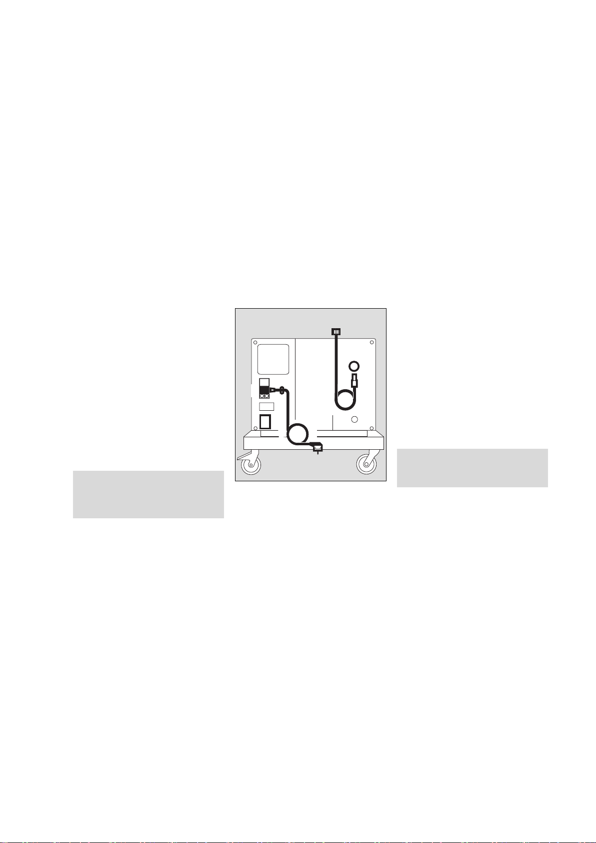
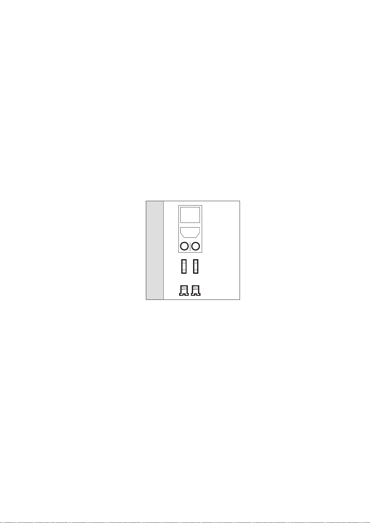
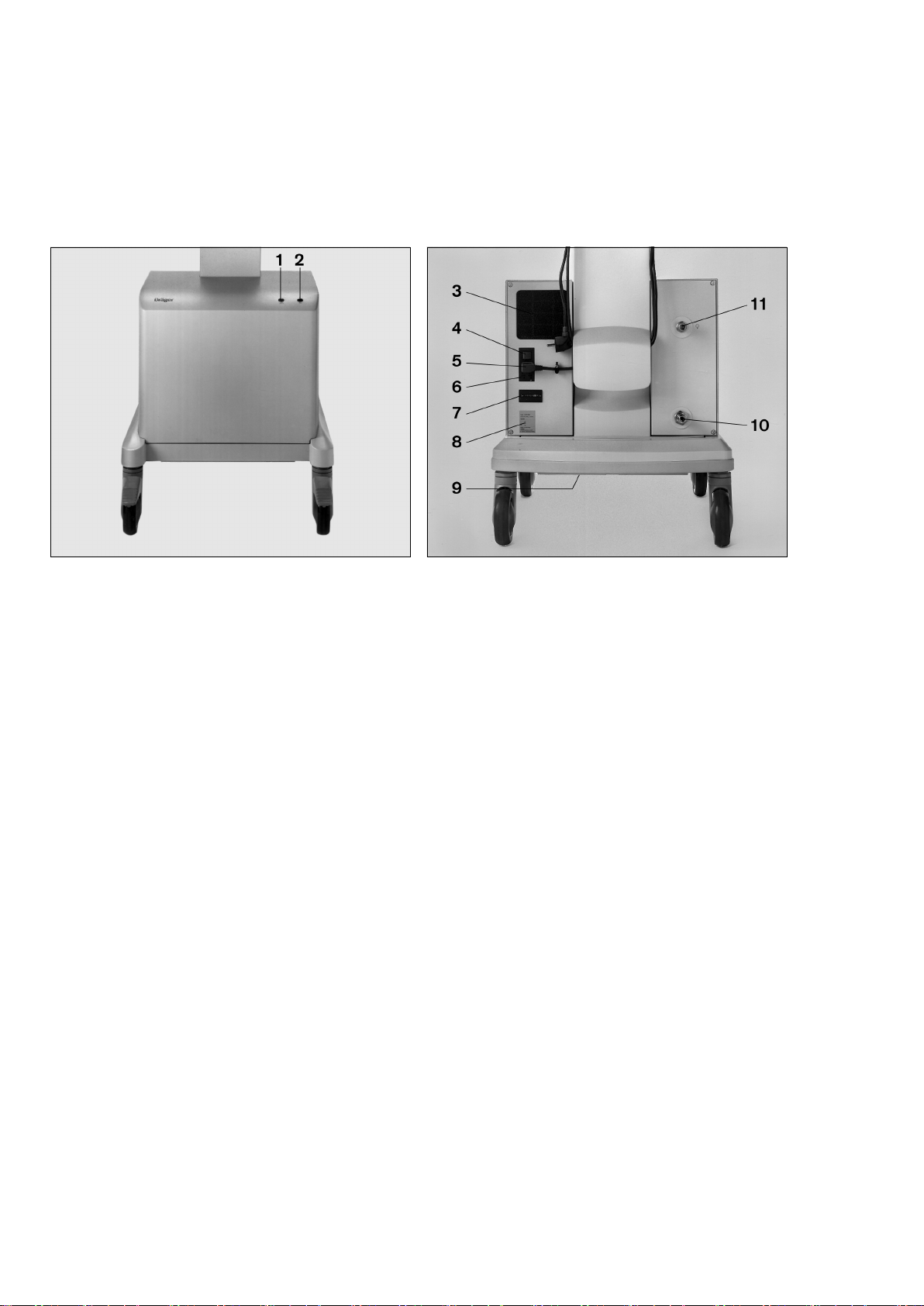
Was ist was
1 Rote Lampe »Temp [« für Übertemperatur
2 Grüne Lampe »
N « für Betrieb/ Bereitschaft
3 Filtermatte
4 Netzschalter
5 Netzkabel
6 Sicherungen
7 Betriebsstundenzähler
8 Typenschild
9 Abluftkanal
10 Anschluss für Druckluft-Anschlussschlauch der zentralen
Druckluftversorgung (nur bei Standby-Geräten)
11 Kupplung für Druckluft-Anschlussschlauch des
Beatmungsgerätes
MT-780-97
What's what
1 Red LED »Temp [« when temperature is too high
2 Green LED »
N « indicates power on / standby
3 Filter mat
4 Main switch
5 Power cable
6 Fuses
7 Operating hours counter
8 Rating plate
9 Exhaust air duct
10 Connection for pressure hose from central medical air
supply (standby apparatus only)
11 Coupling for pressure hose from ventilator
MT-781-97
Page 21

21
Technische Daten Technical Data
Technische Daten
US-Kompressor 115 V/60 Hz/Standby:
1)
Druckluftversorgung
EIN <2,7±0,2 bar
2)
Druckluftversorgung
AUS >3,2±0,2 bar
Umgebungsbedingungen
Betrieb:
Temperatur 10 bis 40
o
C
Rel. Luftfeuchte 30 bis 95 %, keine Betauung
Höhe über dem
Meeresspiegel 0 bis 4000 m
Lagerung:
Temperatur –20 bis 70 oC
Rel. Luftfeuchte 0 bis 99 %, keine Betauung
Höhe über dem
Meeresspiegel 0 bis 16000 m
Leistungskennwerte
Betriebsdruck 4+0,5 bar
Dauerflow minimal 30 L/min bei 3,0 bar
Spitzenflow 180 L/min für max. 0,8 Sekunden
bei insgesamt max. 30 L/min
Taupunktreduzierung
bei Betriebsdruck
5 oC unter Umgebungstemperatur
bei ≥30 L/min und max. Umgebungstemperatur 40 oC.
15 oC unter Umgebungstemperatur bei 15 L/min und max. Umgebungstemperatur 40 oC
Luftqualität Staub- und ölfreie Druckluft
Filter ≤1 µm
Druckluftausgang Verschlusskupplung
Alarm Übertemperaturalarm, optisch
(rote Lampe) und akustisch (Summer mit Dauerton)
Standby – Drucküberwachung
Kompressor – Druckluftversorgung EIN
<2,7–0,3 bar
1)
Kompressor – Druckluftversorgung AUS
>3,4 bar
2)
Technical Data
US Compressor 115 V/60 Hz/Standby:
1)
medical air
ON <2.7±0.2 bar
2)
medical air
OFF >3.2±0.2 bar
Ambient conditions
Operation:
Temperature 10 to 40
o
C
Relative humidity 30 to 95 %, no condensation
Height above sea level 0 to 4000 m
Storage:
Temperature –20 to 70 oC
Relative humidity 0 to 99 %, no condensation
Height above sea level 0 to 16000 m
Performance characteristics
Operating pressure 4+0.5 bar
Continuous flow Minimum 30 L/min at 3.0 bar
Peak flow 180 L/min for max. 0.8 seconds at
a total of max. 30 L/min
Dew point depression
under operating
pressure
5 oC below ambient temperature
at ≥30 L/min and max. ambient
temperature 40 oC.
15 oC below ambient temperature
at 15 L/min and max. ambient temperature 40 oC
Air quality Dust-free and oil-free compressed
air
Filter ≤1 micron
Compressed air outlet Coupling with check valve
Alarm High temperature alarm, visual
(red LED) and acoustic
(continuous buzzer)
Standby – pressure monitoring
Compressor – medical
air ON
<2.7–0.3 bar
1)
Compressor – medical
air OFF
>3.4 bar
2)
Page 22
22
Technische Daten Technical Data
Betriebskennwerte
1)
NIST = Non Interchangeable Screw Thread
(unvertauschbarer Anschluss)
2)
DISS = Diameter Indexed Safety System
(unvertauschbarer Anschluss)
Anschluss für zentrales
Druckluftsystem
NIST1)-Anschluss oder
DISS
2)
-Anschluss
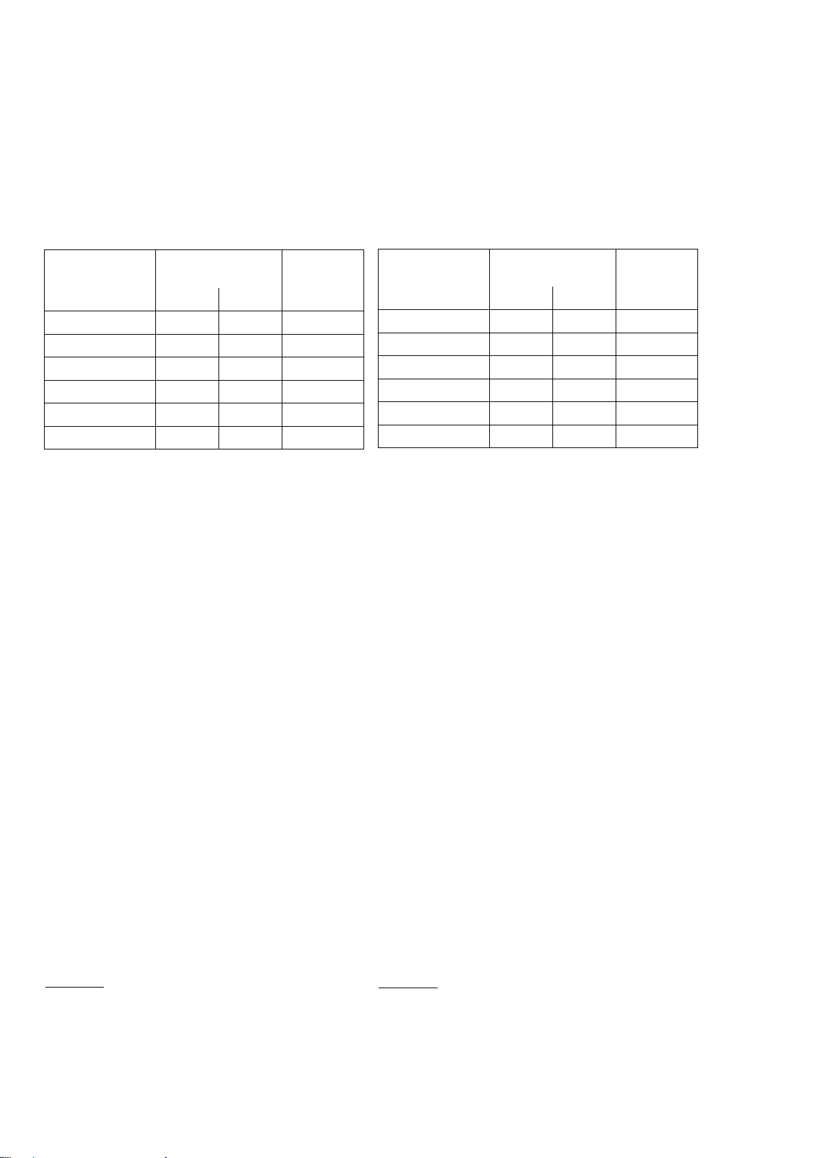
Nennspannung [V] Stromaufnahme
[A]
Sicherungen
bei 50 Hz bei 60 Hz IEC 127-2/V
230 2,3 2,4 T4H250V
Andere Varianten
100 5,9 5,9 T8H250V
110 4,9 5,2 T8H250V
115 4,7 5,0 T8H250V
127 4,2 4,5 T8H250V
Elektromagnetische
Verträglichkeit EMV
geprüft nach EN 60601-1-2
Schalldruckpegel
50 Hz-Geräte typ. 46 - 49 dB (A)
Schalldruckpegel
60 Hz-Geräte typ. 49 - 52 dB (A)
Gewicht ca. 45 kg
Abmessungen
(B x H x T) 50 x 38 x 41 cm
Klassifizierung
gemäß Richtlinie 93/42/EWG
Anhang IX
II a
UMDNS-Code
Universal Medical Device
Nomenclature System Nomenklatur für Medizingeräte
10-972
Operating characteristics
1)
NIST = Non Interchangeable Screw Thread
2)
DISS = Diameter Indexed Safety System
Connection for central
medical air system
NIST1) or
DISS
2)
connection
Nominal voltage [V] Current consumption
[A]
Fuses
at 50 Hz at 60 Hz IEC 127-2/V
230 2.3 2.4 T4H250V
Other versions
100 5.9 5.9 T8H250V
110 4.9 5.2 T8H250V
115 4.7 5.0 T8H250V
127 4.2 4.5 T8H250V
Electromagnetic
compatibility EMC
Tested to EN 60601-1-2
Sound pressure level
50 Hz-Systems: Typically 46 - 49 dB (A)
Sound pressure level
60 Hz-Systems: Typically 49 - 52 dB (A)
Weight Approx. 45 kg
Dimensions
(W x H x D) 50 x 38 x 41 cm
Classification
as per EC Directive 93/42/EEC
Annex IX
II a
UMDNS-Code
Universal Medical Device
Nomenclature System Nomenclature for medical
products
10-972
Page 23
23
Funktionsbeschreibung Functional description
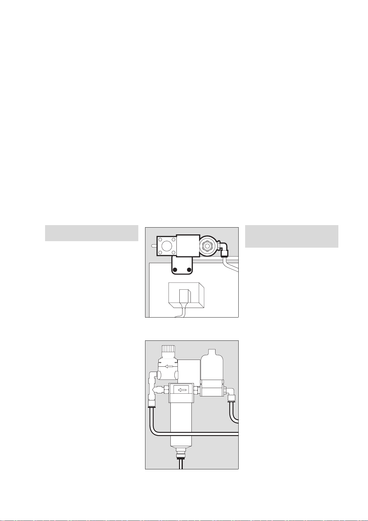
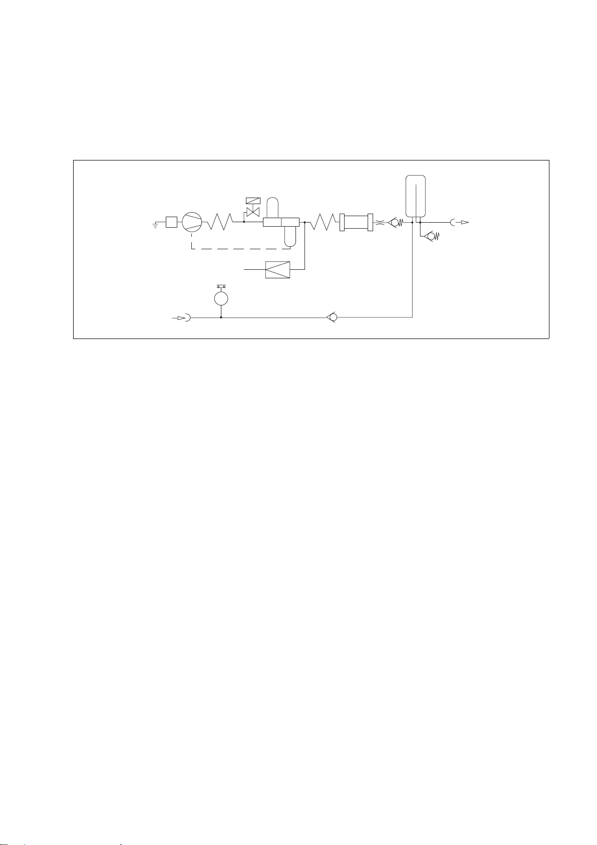
Funktionsbeschreibung
1 Ansaugfilter
2 Kompressoraggregat
3 Kühlspirale
4 Magnetventil
5 Vorfilter
6 Kondensatabscheider
7 Wärmetauscher
8 Druckbegrenzer
9 Membrantrockner
10 Drosseldüse
11 Rückschlagventil
12 Druckbehälter
13 Druckluftausgang
14 Sicherheitsventil
15 Eingang für Standby-Funktion
16 Druckschalter
17 Rückschlagventil
Umgebungsluft wird über das Ansaugfilter 1 angesaugt, im
Kompressoraggregat 2 verdichtet und in der Kühlspirale 3
gekühlt. Das Magnetventil 4 öffnet das System kurzzeitig beim
Start des Kompressors.
Die verdichtete Luft wird im Vorfilter 5 gereinigt, Kondensat
wird im Kondensatabscheider 6 separiert und abgeführt.
Die so behandelte Luft wird im Wärmetauscher 7 wieder
erwärmt, um einen weiteren Kondensatausfall vor dem
Membrantrockner 9 zu vermeiden.
Im nachgeschalteten Membrantrockner 9 wird die Luft auf
einen Taupunkt von mindestens 5
o
C unter Umgebungstem-
peratur entfeuchtet.
03429080
1
2
3
4
5
8
6
9
10
11
12
13
15
16
17
14
7
Functional description
1 Intake filter
2 Compressor unit
3 Cooling coil
4 Solenoid valve
5 Prefilter
6 Condensate trap
7 Heat exchanger
8 Pressure limiter
9 Diaphragm drier
10 Restrictor nozzle
11 Non-return valve
12 Pressure vessel
13 Medical air outlet
14 Relief valve
15 Input for standby mode
16 Pressure switch
17 Non-return valve
Ambient air is drawn in via the intake filter 1, compressed in
the compressor unit 2 and cooled in the cooling coil 3. The
system is briefly opened by solenoid valve 4 when the compressor starts up.
The compressed air is cleaned by prefilter 5. Condensate is
collected and removed in the condensate trap 6.
The purified air is re-heated by the heat exchanger 7 in order to
prevent further condensation forming before it reaches the
diaphragm drier 9.
In the diaphragm drier 9, the air is dehumidified to a dew point
at least 5
o
C below the ambient temperature.
Page 24

24
Funktionsbeschreibung Functional description
Die entfeuchtete Luft gelangt über Drosseldüse 10 und Rückschlagventil 11 in den Druckbehälter 12, wo sie über die
Kupplung 14 entnommen wird.
In Standby-Funktion wird das Beatmungsgerät aus der zentralen Druckluftversorgung über die Kupplung 15, Rückschlagventil 17 und selbstschließende Kupplung 13 versorgt. Das
Kompressoraggregat 2 ist in Standby.
Wenn der Druck in der zentralen Versorgung unter
2,7
–0,3 bar
1)
absinkt, schaltet der Druckschalter 16 das Kom-
pressoraggregat 2 ein.
Steigt der Druck in der zentralen Versorgung auf 3,4 bar
2)
,
schaltet der Druckschalter 16 das Kompressoraggregat 2
wieder aus.
Der Druckregler 8 begrenzt den Systemdruck auf 4 bar, das
Sicherheitsventil 14 schützt vor einem zu hohen Druck aus der
zentralen Versorgung.
1)
US-Kompressor 115 V/60 Hz/Standby:
2,7±0,2 bar
2)
US-Kompressor 115 V/60 Hz/Standby:
3,2±0,2 bar
The dehumidified air flows via the restrictor nozzle 10 and nonreturn valve 11 to the pressure vessel 12, where it is withdrawn via the coupling 14.
In standby mode, the ventilator draws air from the central medical air supply via the coupling 15, non-return valve 17 and
self-closing coupling 13. The compressor unit 2 is on standby.
If the pressure in the central medical air supply drops below
2.7
–0,3 bar
1)
, the compressor unit 2 is activated via pressure
switch 16.
When the pressure in the central medical air supply reaches
3.4 bar
2)
again, the compressor unit 2 is switched off again by
the pressure switch 16.
Pressure regulator 8 limits the system pressure to 4 bar and
relief valve 14 protects the unit against excessively high pressure from the central medical air supply.
1)
US Compressor 115 V/60 Hz/Standby:
2.7±0.2 bar
2)
US Compressor 115 V/60 Hz/Standby:
3.2±0.2 bar
Page 25
25
Bestell-Liste Order List
Bestell-Liste
Benennung Sach-Nr.
System Atemluftkompressor 84 14 350
Atemluftkompressor
Standardversion 230 V, 50 Hz 84 13 890
Option für Standby-Funktion 84 13 939
Druckluft-Anschlussschläuche für
Betrieb des Kompressors im Fahrgestell
von Evita:
NIST-Anschlussschlauch 0,8 m schwarz 84 11 517
NIST-Anschlussschlauch 0,8 m
Gaskennfarbe nach ISO 32 84 11 538
DISS-Anschlussschlauch 0,8 m gelb 84 14 454
Set – Austauschteile für 6000-Stunden
Wartung für Atemluftkompressoren ab
ARMJ 0020 (siehe Typenschild) 84 14 501
Alternativ zum Anschlussschlauch 0,8 m:
NIST-Anschlussschlauch 5 m schwarz 84 11 519
NIST-Anschlussschlauch 5 m
Gaskennfarbe nach ISO 32 84 11 541
Für Standby-Funktion:
NIST-Druckluft- Anschlussschlauch 3 m M 34 408
NIST-Druckluft- Anschlussschlauch 5 m M 34 409
Fahrgestellfuß 84 11 520
Technische Unterlagen auf Anfrage
Order List
Description Order No.
Medical air compressor system 84 14 350
Medical air compressor
Standard version 230 V, 50 Hz 84 13 890
Option for standby mode 84 13 939
Pressure hoses for operating the
compressor on the Evita trolley:
NIST connecting hose 0.8 m, black 84 11 517
NIST connecting hose 0.8 m,
gas colour-coding to ISO 32 84 11 538
DISS connecting hose 0.8 m, yellow 84 14 454
Set of replacement parts for the
6000 hour service for medical air
compressors from ARMJ 0020
(see rating plate) 84 14 501
The following hoses may be ordered
instead of the 0.8 m hose:
NIST connecting hose 5 m, black 84 11 519
NIST connecting hose 5 m,
gas colour-coding to ISO 32 84 11 541
For standby mode:
NIST medical air connecting hose 3 m M 34 408
NIST medical air connecting hose 3 m M 34 409
Trolley 84 11 520
Technical documentation on request
Page 26

Répertoire
26
Índice
Répertoire
Pour votre sécurité, et pour celle de vos patients . . . . . . 27
Consignes pour une utilisation sûre . . . . . . . . . . . . . . . . . . . 28
Utilisation . . . . . . . . . . . . . . . . . . . . . . . . . . . . . . . . . . . . . . . . . 29
Préparation . . . . . . . . . . . . . . . . . . . . . . . . . . . . . . . . . . . . . . . 29
Avant la première mise en service . . . . . . . . . . . . . . . . . . . . . 29
Montage sur le chariot Evita . . . . . . . . . . . . . . . . . . . . . . . . . . 30
Montage sur le chariot séparé pour compresseur seul . . . 33
Branchement du compresseur . . . . . . . . . . . . . . . . . . . . . . . 33
Pour mode de fonctionnement en veille (Option) . . . . . . . . 34
Fonctionnement . . . . . . . . . . . . . . . . . . . . . . . . . . . . . . . . . . . 35
Mode de fonctionnement en veille . . . . . . . . . . . . . . . . . . . . 35
Arrêt . . . . . . . . . . . . . . . . . . . . . . . . . . . . . . . . . . . . . . . . . . . . . . 35
Entretien . . . . . . . . . . . . . . . . . . . . . . . . . . . . . . . . . . . . . . . . . . 36
Périodicité de maintenance . . . . . . . . . . . . . . . . . . . . . . . . . . 37
Dépose du groupe de filtres . . . . . . . . . . . . . . . . . . . . . . . . . 37
Remplacement du filtre préalable . . . . . . . . . . . . . . . . . . . . . 38
Remplacement du filtre principal . . . . . . . . . . . . . . . . . . . . . . 38
Remplacement du filtre d’aspiration . . . . . . . . . . . . . . . . . . . 40
Montage du groupe de filtres . . . . . . . . . . . . . . . . . . . . . . . . 41
Remplacement des fusibles . . . . . . . . . . . . . . . . . . . . . . . . . . 41
Incidents, causes et remèdes . . . . . . . . . . . . . . . . . . . . . . . 42
Vue d’ensemble et légendes . . . . . . . . . . . . . . . . . . . . . . . . 44
Caractéristiques techniques . . . . . . . . . . . . . . . . . . . . . . . 45
Description du fonctionnement . . . . . . . . . . . . . . . . . . . . . . 47
Liste des pièces . . . . . . . . . . . . . . . . . . . . . . . . . . . . . . . . . . . 49
Índice
Para su seguridad y la de sus pacientes . . . . . . . . . . . . . 27
Indicaciones para el uso seguro . . . . . . . . . . . . . . . . . . . . . . 28
Empleo . . . . . . . . . . . . . . . . . . . . . . . . . . . . . . . . . . . . . . . . . . . 29
Preparación . . . . . . . . . . . . . . . . . . . . . . . . . . . . . . . . . . . . . . . 29
Antes de la primera puesta en servicio . . . . . . . . . . . . . . . . . 29
Montaje sobre el soporte móvil Evita . . . . . . . . . . . . . . . . . . 30
Montaje en el soporte móvil adicional . . . . . . . . . . . . . . . . . . 33
Conexión del compresor . . . . . . . . . . . . . . . . . . . . . . . . . . . . 33
Para modo en espera (standby) (Opción) . . . . . . . . . . . . . . 34
Funcionamiento . . . . . . . . . . . . . . . . . . . . . . . . . . . . . . . . . . . 35
Modo en espera (Standby) . . . . . . . . . . . . . . . . . . . . . . . . . . . 35
Fin de funcionamiento . . . . . . . . . . . . . . . . . . . . . . . . . . . . . . . 35
Cuidados . . . . . . . . . . . . . . . . . . . . . . . . . . . . . . . . . . . . . . . . . 36
Intervalos de mantenimiento . . . . . . . . . . . . . . . . . . . . . . . . 37
Desmontaje del grupo filtrante . . . . . . . . . . . . . . . . . . . . . . . 37
Sustitución del filtro previo . . . . . . . . . . . . . . . . . . . . . . . . . . . 38
Sustitución del filtro principal . . . . . . . . . . . . . . . . . . . . . . . . 38
Sustitución del filtro de aspiración . . . . . . . . . . . . . . . . . . . . 40
Montaje del grupo filtrante . . . . . . . . . . . . . . . . . . . . . . . . . . . 41
Sustitución de fusibles . . . . . . . . . . . . . . . . . . . . . . . . . . . . . . 41
Avería – Causa – Remedio . . . . . . . . . . . . . . . . . . . . . . . . . 43
Qué es qué . . . . . . . . . . . . . . . . . . . . . . . . . . . . . . . . . . . . . . . 44
Datos técnicos . . . . . . . . . . . . . . . . . . . . . . . . . . . . . . . . . . . . 45
Descripción del funcionamiento . . . . . . . . . . . . . . . . . . . . . . 47
Lista de pedido . . . . . . . . . . . . . . . . . . . . . . . . . . . . . . . . . . . . 49
Page 27

27
Pour votre sécurité, et pour celle de vos patientsPara su seguridad y la de sus pacientes
Pour votre sécurité, et pour celle de
vos patients
Observer la notice d’utilisation
Toute manipulation de l’appareil présuppose la connaissance
et l’observation exactes de cette notice d’utilisation. L’appareil
est uniquement destiné à l’utilisation décrite.
Maintien en état
L’appareil doit être soumis toutes les 6.000 heures de service
(et au moins une fois par an ou tous les 6 mois) à un contrôle
et une prestation de maintenance qui doivent être effectués
par des spécialistes (avec procès-verbal).
Réparations de l’appareil uniquement par des spécialistes.
Nous recommandons de conclure un contrat de maintenance
avec le service après-vente Dräger.
Pour les réparations, n’utiliser que les pièces de la société
Dräger.
Observer le chapitre "Périodicité de maintenance".
Accessoires
N’utiliser que les accessoires figurant dans la liste des pièces.
Responsabilité du fonctionnement et/ou des dommages
Le fonctionnement de l’appareil est sous la responsabilité du
propriétaire ou de l’utilisateur seul dans tous les cas où il est
entretenu ou réparé de manière non appropriée par des personnes n’appartenant pas au service après-vente Dräger, ou si
l’appareil a été manipulé de manière non conforme à l’utilisation à laquelle il est destiné.
Dräger n’est pas responsable des dommages résultant de
l’inobservation des remarques ci-dessus. Les conditions de
garantie et de responsabilité des conditions de vente et de
livraison de Dräger ne sont pas élargies par les remarques cidessus.
Dräger Medical AG & Co. KG
Para su seguridad y la de sus
pacientes
Observar las instrucciones de uso
Cualquier manipulación del aparato presupone el conocimiento exacto y la estricta observación de estas instrucciones
de uso. El aparato está destinado únicamente al uso aquí
descrito.
Mantenimiento
El aparato debe ser sometido cada 6.000 horas de funcionamiento, o al menos una vez al año / cada seis meses, a trabajos de inspección y mantenimiento por personal especializado
(llevándose un registro escrito de ello).
Las reparaciones del aparato únicamente pueden ser llevadas
a cabo por personal especializado.
Recomendamos el Servicio técnico Dräger para la firma de un
contrato de mantenimiento y para las reparaciones.
Emplear únicamente piezas originales Dräger en el mantenimiento y reparación de los aparatos.
Observar el capítulo "Intervalos de mantenimiento".
Accesorios
Utilizar únicamente los accesorios reflejados en la lista de
pedido.
Garantía de funcionamiento o daños
La garantía de funcionamiento se extinguirá, pasando la responsabilidad al propietario u operador, cuando se realicen trabajos de mantenimiento o reparación inadecuados por
personal ajeno al Servicio técnico Dräger o si el aparato es utilizado de forma no conforme a su uso previsto.
Dräger no responde de los daños causados por la no observancia de las recomendaciones dadas anteriormente. Las cláusulas de garantía y responsabilidad de las condiciones de
venta y entrega de Dräger no se ven modificadas por las recomendaciones anteriores.
Dräger Medical AG & Co. KG
Page 28

28
Pour votre sécurité, et pour celle de vos patients Para su seguridad y la de sus pacientes
Consignes pour une utilisation sûre
Ne pas utiliser dans les zones présentant un danger
d’explosion
L’appareil n’est pas homologué pour l’utilisation dans les
zones explosives.
Branchement à d'autres appareils électriques
Ne pas procéder au couplage électrique avec des appareils
qui ne sont pas mentionnés dans la présente notice d'utilisation sans avoir consulté au préalable les fabricants ou un
spécialiste.
Alimentation d'appareils médicaux de ventilation destinés
au maintien de la vie
Si le compresseur est utilisé pour l’alimentation de respirateurs vitaux, prévoir un dispositif de réserve garantissant une
alimentation suffisante en air comprimé en cas de défaillance
du compresseur !
Les respirateurs vitaux alimentés par le compresseur doivent
disposer d’une fonction d’alerte en cas de pression d’alimentation insuffisante !
Tout appareil électrique médical exige des précautions spéciales en ce qui concerne la compatibilité électromagnétique
(EMC) ; il doit également être installé et mis en service conformément aux informations CEM fournies dans la documentation technique disponible chez DrägerService sur demande.
Les téléphones portables et les équipements de communication RF mobile peuvent nuire au bon fonctionnement de l’équipement électrique médical.
Les broches des connecteurs marqués par le symbole d’avertissement ESD ne peuvent pas être touchés ni connectés sans prendre les mesures de
précautions ESD adéquates. De telles mesures de
précaution peuvent inclure : porter des vêtements
et des chaussures antistatiques, toucher une borne de masse
avant et pendant la connexion des broches ou utiliser de gants
antistatiques et électriquement isolés. Tout le personnel impliqué dans l’opération susmentionnée recevra des instructions
précises pour entreprendre lesdites mesures.
Ne pas utiliser en présence de gaz inflammables et
d’anesthésiques. Risque d’incendie !
Ne pas pulvériser de liquides inflammables à proximité
du compresseur. Risque d’incendie !
Éviter les substances toxiques dans l‘air de la pièce !
Le compresseur aspire l‘air ambiant. Les substances toxiques risqueraient d‘atteindre le patient.
Généralités en matière de compatibilité électromagnétique (CEM) selon la norme internationale CEM
CEI 60601-1-2 : 2001
Indicaciones para el uso seguro
No utilizar en áreas expuestas a peligro de explosión
El aparato no está autorizado para ser usado en áreas donde
exista peligro de explosión.
Acoplamiento sin riesgo con otros aparatos eléctricos
El acoplamiento eléctrico con aparatos no mencionados en
estas instrucciones de uso sólo se llevará a efecto previa
consulta a correspondiente fabricante o a un perito.
Abastecimiento de respiradores artificiales
Si se utiliza el compresor para la alimentación de aparatos de
respiración de soporte vital, hay que tener prevista una alimentación de aire comprimido alternativa suficiente para el caso
de que se produzca una avería en el compresor.
Los aparatos de respiración de soporte vital que sean alimentados por compresores deben estar dotados de una función
de alarma de presión de alimentación insuficiente.
Debe tomarse una especial precaución con los equipos eléctricos médicos con relación a la compatibilidad electromagnética (EMC) y su instalación y puesta en servicio debe
realizarse de conformidad con la información de EMC proporcionada en la documentación técnica que puede obtener de
DrägerService cuando lo solicite.
Los equipos de comunicaciones de RF móviles y portátiles
pueden afectar al equipo eléctrico médico.
Las patillas de los conectores que incorporen el
símbolo de advertencia de descargas electrostáticas (ESD) no se deberán tocar ni conectar a menos
que se apliquen los procedimientos preventivos
sobre ESD. Entre estos procedimientos preventivos se puede incluir el uso de vestimenta y calzado antiestáticos, tocar un elemento conectado a tierra antes y durante la
conexión de las patillas o el uso de guantes antiestáticos y de
aislamiento eléctrico. Todo el personal implicado en los procedimientos anteriores, deberán recibir instrucciones sobre
estos procedimientos.
No usarlo en presencia de gases o agentes anestésicos
inflamables ¡Peligro de incendio!
No pulverizar líquidos inflamables en las proximidades
del compresor ¡Peligro de incendio!
¡Evitar las sustancias nocivas en el aire ambiente!
El compresor aspira aire ambiente. En caso dado, las sustancias nocivas llegarían hasta el paciente.
Información general sobre compatibilidad electromagnética (EMC) de conformidad con la norma internacional
IEC 60601-1-2: 2001
Page 29

29
Préparation Preparación
Utilisation
Compresseur d’air permettant d’alimenter un respirateur médical en air comprimé.
Préparation
Avant la première mise en
service
Le compresseur est livré sans chariot. Il
peut être monté soit sur le chariot Evita,
soit sur le chariot séparé pour compresseur seul.
Montage uniquement par des
spécialistes.
Outillage nécessaire :
Clé pour vis à tête à six pans en
creux de 5,
tournevis cruciforme, taille 2,
clé plate de 19.
Ne faire fonctionner le compresseur
d’air médical qu’après montage sur
le chariot.
Risque d’endommagement du groupe
compresseur si la circulation d’air est
insuffisante !
Empleo
Compresor de aire para la alimentación
de aparatos de respiración con aire
comprimido medicinal.
Preparación
Antes de la primera puesta en
servicio
El compresor se entrega sin bastidor
móvil. Puede ser montado sobre el
soporte móvil Evita o sobre el soporte
móvil adicional.
El montaje debe ser realizado únicamente por personal especializado.
Herramientas necesarias:
llave Allen para tornillos de cabeza con
hexágono interior SW 5,
destornillador para tornillos de cabeza
ranurada en cruz, del número 2,
llave de boca SW 19.
Poner en marcha el compresor de
aire de respiración una vez montado
en el soporte móvil.
En caso contrario el grupo compresor
puede dañarse debido a la falta de circulación de aire.
Page 30
Préparation
30
Preparación
Montage sur le chariot Evita
● Déposer le respirateur du
chariot Evita.
● Coucher le chariot Evita sur le sol de
façon à ce que sa face inférieure soit
accessible.
1 Visser la tôle d’évacuation d’air sous
le cadre du chariot avec les vis cruciformes jointes.
● Remettre le chariot sur ses roulettes.
2 Extraire la garniture de mousse du
chariot.
● Découper la garniture de mousse le
long de la ligne de repère.
3 Remettre les deux moitiés en place
dans le chariot.
4 Dévisser les deux vis du couvercle de
la batterie, puis extraire le couvercle
de la batterie.
● Dévisser les deux vis sous le couver-
cle de la batterie.
01429080
11
1
1
01529080
2
01629080
✂
33
01729080
44
Montaje sobre el soporte
móvil Evita
● Retirar el aparato respirador del
bastidor móvil Evita.
● Tumbar en el suelo el bastidor móvil
Evita para que se pueda acceder a su
cara inferior.
1 Atornillar bajo el marco del bastidor
móvil la caperuza de escape de aire
con los tornillos de cabeza con
ranura en cruz adjuntos.
● Volver a colocar el soporte móvil
sobre sus ruedas.
2 Sacar la estera de gomaespuma del
soporte móvil.
● Cortar la estera de gomaespuma por
la línea de corte prevista.
3 Volver a colocar las dos piezas en el
bastidor móvil.
4 Desatornillar los dos tornillos de la
tapa de la batería, retirar la tapa de la
batería.
● Desatornillar los dos tornillos situa-
dos debajo de la tapa de la batería.
Page 31

31
Préparation Preparación
Sur le compresseur :
1 Dévisser les quatre vis à tête à six
pans en creux au dos du compresseur.
2 Faire coulisser avec précaution le
capot sur environ 10 cm seulement.
Ne pas l’ouvrir plus afin de ne pas
arracher le câble du témoin lumineux.
3 Dévisser la vis cruciforme située sur
la fiche, retirer entièrement le capot.
4 Mettre le compresseur sur le chariot.
Le réservoir d’air comprimé doit se
trouver à côté du montant.
5 Visser le compresseur sur le chariot
en utilisant les quatre vis à tête à six
pans en creux et les rondelles.
S’assurer que la fiche du câble secteur est bien débranchée. Risque de
décharge électrique !
00129080
1
1
1
1
03829080
2
approx. 10 cm/aprox. 10 cm
01829080
3
00529080
5
5
4
55
En el compresor:
1 Desatornillar los cuatro tornillos de
cabeza con hexágono interior situados en la parte posterior.
2 Desplazar hacia atrás cuidadosa-
mente la cubierta unos 10 cm sin que
se rompa el cable de la lámpara indicadora.
3 Desatornillar el tornillo de cabeza en
cruz la conexión de red. Sacar la
conexión de red. Retirar totalmente la
cubierta.
4 Colocar el compresor sobre el
soporte móvil. Emplazar el depósito
de aire comprimido junto a la
columna.
5 Atornillar fuertemente el compresor
al soporte móvil con los cuatro tornillos de cabeza con hexágono interior
y las arandelas.
Asegurarse de que el enchufe está
desconectado de la red. En caso
contrario existe el peligro de recibir
una descarga eléctrica.
Page 32

Préparation
32
Preparación
1 Dévisser les quatre vis à tête à six
pans en creux de la sécurité de transport.
2 Extraire les deux languettes de la
sécurité de transport.
3 Brancher la fiche du moteur et la fixer
à l’aide de la vis cruciforme.
Conserver les languettes et les vis de
la sécurité de transport pour un éventuel transport ultérieur
● Mettre le capot en place, brancher sa
fiche et la fixer avec la vis cruciforme.
● Faire coulisser le capot en position
fermée et visser les quatre vis à tête à
six pans en creux au dos de l’appareil.
Retirer la sécurité de transport avant
chaque mise en service. Sinon,
l’appareil sera exposé à de fortes
vibrations qui risquent d’endommager le groupe compresseur !
Pour tout transport dans des conditions autres que les conditions normales de transport sur le chariot :
Mettre la sécurité de transport en
place. Sinon, risque d’endommagement des pieds en caoutchouc.
01929080
1
1
1
1
02029080
3
2 2
1 Desatornillar los cuatro tornillos de
cabeza con hexágono interior del dispositivo de seguridad para el transporte.
2 Sacar las dos orejas de fijación del
dispositivo de seguridad para el
transporte tirando de ellas.
3 Enchufar el conector del motor y ase-
gurarlo con el tornillo de cabeza en
cruz. Guardar las orejas de fijación y
los tornillos del dispositivo de seguridad para el transporte par futuros
transportes.
● Colocar la cubierta, introducir su
conector y asegurarlo con el tornillo
de cabeza en cruz.
● Cerrar la cubierta por deslizamiento y
atornillar los cuatro tornillos de
cabeza de hexágono interior a la
parte posterior.
Antes de cada puesta en servicio por
primera vez, retirar el dispositivo de
seguridad para el transporte. En
caso contrario se originan fuertes
vibraciones en el compresor de aire
de respiración. El grupo compresor
puede dañarse.
Cuando se vaya a transportar el
equipo, siempre que no sea el habitual desplazamiento sobre el bastidor móvil:
montar el dispositivo de seguridad
para el transporte. En caso contrario
se pueden dañar los apoyos de
goma.
Page 33

33
Préparation Preparación
Montage sur le chariot séparé
pour compresseur seul
Pour le montage du compresseur sur le
chariot, procéder de la même manièr
que pour le montage sur le chariot Evita.
Branchement du compresseur
1 S’assurer que la tension de fonction-
nement indiquée sur l’étiquette de
type placée au dos du compresseur
correspond bien à celle du réseau.
2 Dévisser le collier de serrage.
3 Brancher la fiche de l’appareil, ten-
dre le câble, le faire passer dans le
collier et
2 visser le collier de serrage.
4 Toujours brancher le cordon d’ali-
mentation sur une prise secteur
munie d’une fiche de terre. Ne pas
utiliser d’adaptateur.
5 Visser le flexible d’air comprimé sur
le respirateur.
6 Enfoncer l’embout du flexible d’air
comprimé dans le raccord du compresseur. Le raccord doit s’enclencher une fois en place.
● Placer le compresseur si possible
dans un endroit frais, et pas devant
un radiateur ou toute autre source de
chaleur.
Veiller à ce que la circulation d’air
s’effectue sans gêne autour du compresseur.
● Ne pas utiliser le compresseu dans
un environnement salin. Les clapets
anti-retour du compresseur pourraient se corroder.
Ne pas raccorder plusieurs respirateurs au compresseur ! Risque de
surcharge du compresseur.
02129080
5
6
4
1
2
3
Montaje en el soporte móvil
adicional
Efectuar el montaje del compresor como
con el bastidor móvil Evita.
Conexión del compresor
1 Comprobar que el voltaje de servicio
indicado en la placa de características situada en la parte posterior coincide con el voltaje de red.
2 Desatornillar la abrazadera.
3 Introducir el conector del aparato,
tensar el cable, fijarlo debajo de la
abrazadera y
2 atornillar la abrazadera.
4 Introducir el conector de enchufe a la
red en una caja de enchufe con toma
de tierra. No utilizar ningún enchufe
adaptador.
5 Enroscar la manguera de conexión
del aire comprimido al aparato respirador.
6 Introducir firmemente el conector de
la manguera de conexión de aire
comprimido en el dispositivo de
enganche del compresor – hasta su
enclavamiento.
● Colocar el compresor en un lugar lo
más fresco posible, no delante de
radiadores de calefacción u otras
fuentes de calor.
Asegurar la libre circulación del aire
alrededor del compresor.
● No operar el compresor en ambien-
tes salinos. De lo contrario, las válvulas de retención del compresor
podrían corroerse.
No conectar al compresor varios
aparatos de respiración. Se puede
sobrecargar el compresor.
Page 34

Préparation
34
Preparación
Pour mode de fonctionnement
en veille (Option)
Pour assurer l’alimentation du respirateur en cas d’incident sur le réseau principal d’air comprimé.
1 Visser le flexible d’air comprimé sur
le compresseur.
2 Enfoncer son raccord dans la prise
murale du réseau principal d’air comprimé.
02229080
2
1
Para modo en espera
(standby) (Opción)
Para la alimentación del aparato respirador en el caso de fallo en el sistema centralizado de aire comprimido:
1 enroscar la manguera de conexión
de aire comprimido al compresor,
2 introducir el conector en la toma de
pared del sistema centralizado de
aire comprimido.
Page 35

35
Fonctionnement Funcionamiento
Fonctionnement
Si le compresseur a été entreposé à des
températures de moins de 3 °C :
● Attendre environ 2 heures pour que
le compresseur s’adapte à la température ambiante.
1 Appuyer sur l’interrupteur de mise
sous tension au dos de l’appareil,
2 le témoin lumineux vert »
N « situé à
l’avant du capot s’allume = MACHE.
● Mettre en service le respirateur qui
est branché au compresseur.
En cas de dérangement, se reporter au
chapitre "Incidents, causes et remèdes"
à la page 42.
Mode de fonctionnement en
veille
Pour assurer l’alimentation en air comprimé en cas d’incident sur le circuit
principal.
● Toujours laisser l’interrupteur de
mi se s ous ten sion e n po sit ion de m arche = le témoin lumineux vert »
N « à
l’avant du capot doit donc rester
allumé.
Le compresseur sous tension surveille la
pression du circuit d’alimentation principal :
Si la pression descend sous
2,7
0.3 bar
1)
, le compresseur prend automatiquement le relais, et alimente ainsi
le respirateur branché sur celuici en air
comprimé. Dès que la pression remonte
au-delà de 3,4 bar2) sur le circuit d’alimentation principal, le compresseur
s’arrête et repasse en mode de veille.
Arrêt
Après avoir coupé le respirateur :
● Appuyer sur l’interrupteur de tension
au dos de l’appareil,
● le témoin lumineux vert » N « s’éteint
= ARRET
Le compresseur se purge automatiquement.
1)
Compresseur US 115 V/60 Hz/veille :
2,7±0,2 bar
2)
Compresseur US 115 V/60 Hz/veille :
3,2±0,2 bar
02329080
1
01029080
2
Funcionamiento
Si se tuvo almacenado el compresor a
temperaturas inferiores a 3 °C:
● esperar unas dos horas a que se
igualen las temperaturas.
1 Apretar el interruptor principal de red
situado en la parte posterior,
2 la lámpara verde »
N « situada
delante en la cubierta se enciende
= CONECTADA.
● Poner en funcionamiento el aparato
respirador conectado.
En caso de avería, véase "Avería Causa - Remedio" en la página 43.
Modo en espera (Standby)
Para la alimentación del aparato respirador en el caso de fallo en el sistema centralizado de aire comprimido:
● dejar siempre conectado el interrup-
tor de red = la lámpara verde »
N «
de la parte delantera de la cubierta
permanece encendida.
El compresor conectado supervisa la
presión del sistema centralizado de aire
comprimido: si la presión cae por debajo
de 2,7
–0.3 bar
1)
, el compresor toma
automáticamente a su cargo la alimentación con aire comprimido del aparato
respirador conectado a él. Si la presión
del sistema centralizado de aire comprimido vuelve a subir por encima de
3,4 bar
2)
, el compresor se desconecta y
queda en modode espera.
Fin de funcionamiento
Una vez desconectado el aparato respirador:
● apretar el interruptor de red situado
en la parte posterior,
● la luz verde » N « se apaga
= DESCONECTADA.
El compresor se descarga automáticamente.
1)
Compresor US 115 V/60 Hz/Standby:
2,7±0,2 bar
2)
Compresor US 115 V/60 Hz/Standby:
3,2±0,2 bar
Page 36

Entretien
36
Cuidados
Entretien
Si le filtre est colmaté :
1 Extraire le filtre, le nettoyer en le
battant légèrement, puis le remettre
en place.
● Enlever les salissures sur le corps du
compresseur à l’aide d’un chiffon à
jeter.
Désinfection du corps du compresseur par essuyage
Pour la désinfection, utiliser des produits désinfectants pour surfaces. Pour
des raisons de compatibilité des matériaux, utiliser des produits à base de
— aldéhydes,
— composés quaternaires d’ammo-
nium.
N’utiliser en aucun cas des produits à
base de
— composés phénoliques,
— composés qui dissocient les halogè-
nes en leurs éléments,
— acides organiques forts,
— composés qui dissocient l’oxygène
en ses éléments.
● Désinfection par essuyage p. ex. avec
Incidur
®
(Fa. Henkel-Ecolab
Deutschland GmbH)
● Tenir compte des instructions d’utili-
sation du fabricant du produit.
02429080
1
Cuidados
Cuando el material filtrante esté sucio:
1 Extraer el material filtrante, sacudirlo
para que se desprenda la suciedad,
volver a colocar el material filtrante.
● Eliminar la suciedad de la caja del
compresor con un paño desechable.
Desinfección de la caja
Utilizar para la desinfección productos
del grupo de desinfectantes de superficies. Por motivos de compatibilidad de
materiales son apropiados productos a
base de:
— aldehidos
— compuestos de amonio cuaternario
Debido al peligro de que se dañen los
materiales, no son adecuados productos
a base de:
— compuestos fenólicosl,
— compuestos que desprendan halóge-
nos,
— ácidos orgánicos fuertes,
— disociaciones de compuestos de oxi-
geno.
● Desinfección por frotamiento p.ej.
con Incidur
®
(Fa. Henkel-Ecolab
Deutschland GmbH)
● Observar las instrucciones de uso
del fabricante.
Page 37

37
Périodicité de maintenance Intervalos de mantenimiento
Périodicité de
maintenance
Maintenance uniquement par des spécialistes
Si nécessaire, procéder à la maintenance à intervalles plus rapprochés.
Si l’appareil n’a pas fonctionné pendant
6000 heures :
● Procéder à un contrôle et à la mainte-
nance au plus tard au bout d’un an.
Éliminer le filtre usagé avec les ordures
ménagères.
Dépose du groupe de filtres
Déposer le capot, voir page 31.
1 Dévisser les deux vis cruciformes.
2 Déposer les flexibles :
Repousser l’anneau et, tout en le
maintenant repoussé, tirer le flexible
hors du raccord.
● Extraire le groupe de filtres.
au plus tard toutes
les 6000 heures
de service :
(compteur de
marche horaire)
remplacement
des filtres :
filtre préalable,
filtre principal,
filtre d’admission d’air
Débrancher le cordon d’alimentation ! Risque de décharge
électrique !
03029080
1
1
02829080
2
2
2
Intervalos de
mantenimiento
Mantenimiento por personal especializado
En caso necesario, realizar el mantenimiento a intervalos más cortos.
Si el aparato no ha estado aún
6000 horas en funcionamiento:
● Realizar una inspección y manteni-
miento a más tardar después de
transcurrir un año.
Eliminar los filtros sucios junto con los
desechos domésticos
.
Desmontaje del grupo filtrante
Quitar la caja, véase la página 31.
1 Desatornillar y retirar ambos tornillos
de cabeza en cruz.
2 Quitar las mangueras:
Mantener apretado el anillo y tirar al
mismo tiempo de la manguera hasta
desconectarla.
● Sacar el grupo filtrante.
a más tardar
después de cada
6000 horas de
funcionamiento:
(véase Contador de
horas de funcionamiento)
Sustitución
de filtros:
filtro previo
filtro principal
filtro de
aspiración
Desconectar el enchufe de la red.
Peligro de recibir una descarga eléctrica en caso contrario.
Page 38

Périodicité de maintenance
38
Intervalos de mantenimiento
Remplacement du filtre
préalable
1 Dévisser le boîtier à la main.
2 Dévisser la vis cruciforme et la retirer
avec la rondelle plastique.
3 Extraire la cartouche filtrante et la
remplacer par une cartouche neuve.
3 Mettre la cartouche filtrante en place.
2 Visser avec la vis cruciforme et la ron-
delle plastique.
4 Retirer le joint torique usagé, mettre
un joint torique neuf en place.
● Visser fermement le boîtier à la main.
Remplacement du filtre
principal
5 Tenir le cliquet tiré, et en même
temps
6 tourner le boîtier jusqu’à ce que les
repères ( II ) coïncident.
● Retirer le boîtier.
03129080
1
2
3
4
02629080
5
66
Sustitución del filtro previo
1 Desenroscar la carcasa con la mano.
2 Desenroscar el tornillo de cabeza en
cruz y retirarlo con la arandela de
material sintético.
3 Extraer el casquillo filtrante y cam-
biarlo por uno nuevo.
3 Colocar un nuevo casquillo filtrante.
2 Enroscar fijamente con ayuda del tor-
nillo de cabeza en cruz y la arandela
de material sintético.
4 Extraer la junta toroidal vieja, e incor-
porar una nueva.
● Enroscar fuertemente la carcasa con
la mano.
Sustitución del filtro principal
5 Tirar del trinquete y simultáneamente
6 girar la carcasa hasta que coincidan
las marcas ( II ).
● Extraer la carcasa.
Page 39

39
Périodicité de maintenance Intervalos de mantenimiento
1 Enlever le joint torique usagé du boî-
tier, mettre un joint torique neuf en
place.
2 Dévisser à la main la cartouche fil-
trante usagée et visser la cartouche
filtrante neuve.
● Mettre le boîtier en place de façon à
ce que les repères coïncident et
ltourner jusqu’à ce que le cliquet
s’enclenche de manière audible.
● En tirant légèrement dessus,
s’assurer que le boîtier s’est bien
enclenché.
03729080
1
02729080
2
1 Quitar la junta toroidal vieja de la car-
casa, montar una junta toroidal
nueva.
2 Desenroscar manualmente el casqui-
llo filtrante viejo y enroscar un casquillo filtrante nuevo.
● Colocar la carcasa de forma que
coincidan las marcas y girarla hasta
que se oiga cómo se enclava el trinquete.
● Tirando suavemente, comprobar que
la carcasa está enclavada.
Page 40

Périodicité de maintenance
40
Intervalos de mantenimiento
Remplacement du filtre
d’aspiration
1 Dévisser les deux vis avant à tête à six
pans en creux sur les tôles de montage du groupe compresseur et desserrer de deux tours seulement les
deux vis arrière à six pans en creux.
2 Dévisser le flexible d’air comprimé
avec une clé plate de 19, tout en
maintenant avec une deuxième clé
plate le raccord en direction de
l’échangeur thermique de façon à ce
qu’il ne risque pas de se desserrer.
● Extraire le groupe compresseur juste
assez pour que le tuyau de sortie à
l’arrière du boîtier du filtre ne
dépasse plus de l’orifice.
3 Tourner le boîtier du filtre dans le
sens des aiguilles d’une montre et le
déposer.
4 Extraire le filtre d’aspiration usagé et
mettre un filtre neuf en place dans le
boîtier.
● Installer le boîtier du filtre avec le
tuyau dirigé vers l’arrière, il doit se
trouver approximativement en position "11 heures".
3 Tourner le boîtier du filtre en sens
inverse des aiguilles d’une montre
jusqu’à ce qu’il soit verrouillé. Le
tuyau est alors en position horizontale.
● Contrôler en tirant dessus si le boîtier
du filtre est solidement fixé.
● Repousser le groupe compresseur
en faisant pénétrer le tuyau dans l’orifice.
2 Visser le flexible d’air comprimé avec
une clé plate de 19 tout en maintenant avec une deuxième clé plate le
raccord en direction de l’échangeur
thermique de façon à ce qu’il ne risque pas de se desserrer.
1 Visser le groupe compresseur avec
les vis avant et arrière à tête à six pans
en creux.
03329080
3
1
1
2
03229080
4
Sustitución del filtro de
aspiración
1 Desatornillar y sacar los dos tornillos
anteriores de cabeza con hexágono
interior situados en las chapas de
montaje del grupo compresor; soltar
dos vueltas los dos tornillos posterio-
res de cabeza con hexágono interior.
2 Desenroscar la manguera de aire
comprimido mediante la llave de
boca SW 19. Con una segunda llave
de boca impedir que se separe la
pieza de unión con el intercambiador
de calor.
● Tirar hacia afuera del grupo compre-
sor hasta que el tubo de salida poste-
rior de la carcasa del filtro ya no
sobresalga por la abertura.
3 Girar la carcasa del filtro en el sen-
tido de las agujas del reloj y retirarla.
4 Sacar el filtro de aspiración viejo y
colocar uno nuevo en la carcasa del
filtro.
● Colocar la carcasa del filtro con el
tubo mirando hacia atrás, aproxima-
damente en posición "11 horas".
3 Girar la carcasa del filtro en el sen-
tido contrario a las agujas del reloj
hasta que se quede bloqueado. El
tubo queda en posición horizontal.
● Comprobar tirando de ella que la car-
casa del filtro asienta firmemente.
● Deslizar hacia atrás el grupo compre-
sor introduciendo al mismo tiempo el
tubo en la abertura.
2 Apretar fuertemente la manguera de
aire comprimido con la llave de boca
SW 19. Con una segunda llave de
boca impedir que se separe la pieza
de unión con el intercambiador de
calor.
1 Fijar el grupo compresor con los tor-
nillos de cabeza de hexágono interior
anteriores y posteriores.
Page 41

41
Périodicité de maintenance Intervalos de mantenimiento
Montage du groupe de filtres
● Raccorder les flexibles au grou-
peande filtres, voir page 37.
● Visser le groupe de filtres, voir
page 37.
● Mettre le capot en place, brancher sa
fiche électrique et la fixer avec la vis
cruciforme.
● Refermer le capot et visser les quatre
vis à tête à six pans en creux au dos
de l’appareil.
Remplacement des fusibles
● Débrancher le cordon d’alimentation.
1 Avec un tournevis, tourner les bou-
chons en sens inverse des aiguilles
d’une montre et les extraire.
2 Extraire de leurs bouchons les fusi-
bles qui ont sauté et y installer à leur
place des fusibles neufs – n’utiliser
que les fusibles spécifiés dans les
"Caractéristiques techniques" à la
page 45.
1 Revisser les bouchons avec les fusi-
bles neufs.
Mise au rebut de l‘appareil
— à la fin de la phase d‚utilisation.
● Mettre l‘appareil au rebut conformé-
ment à la réglementation en vigueur
et après consultation de l'entreprise
d‘élimination des déchets compétente. Observer les dispositions légales en vigueur !
Ce dispositif est soumis à la Directive
européenne 2002/96/EC (DEEE). Il
n'est pas enregistré pour un usage à
domicile et ne peut être mis au rebut aux
points de collecte municipaux réservés
aux déchets d'équipement électrique et
électronique.
Dräger Medical a donné à une société
son autorisation pour mettre au rebut ce
dispositif de manière appropriée : pour
de plus amples informations, contactez
votre représentant local Dräger Medical.
03529080
2
1
Montaje del grupo filtrante
● Conectar las mangueras al grupo fil-
trante. Véase la página 37.
● Atornillar el grupo filtrante. Véase la
página 37.
● Colocar la tapa, conectar el enchufe
eléctrico y fijarlo con el tornillo de
cabeza en cruz.
● Cerrar por deslizamiento la tapa y
atornillar en la parte posterior los cuatro tornillos de cabeza con hexágono
interior.
Sustitución de fusibles
● Desenchufar de la red.
1 Girar las caperuzas con el destorni-
llador en el sentido contrario a las
agujas del reloj y retirarlas.
2 Sacar de las caperuzas los fusibles
fundidos y colocar fusibles nuevos.
Utilizar únicamente los fusibles prescritos. Véase "Datos técnicos",
página 45.
1 Volver a atornillar las caperuzas con
los fusibles nuevos.
Eliminación del equipo
— al final de la fase de utilización.
● El aparato se tiene que entregar a
una empresa local competente para
facilitar su eliminación conforme a las
disposiciones ecológicas vigentes.
¡Es imprescindible observar las disposiciones legales locales vigentes!
Este dispositivo cumple con la Directiva
2002/96/CE (RAEE) de la UE. No está
homologado su uso en ámbitos privados
y no se puede desechar en los puntos
municipales de recogida de residuos de
aparatos eléctricos y/o electrónicos.
Dräger Medical ha autorizado una
empresa para que se encargue de la
recogida y destrucción correcta del aparato. Póngase contacto con su representante local de Dräger Medical si desea
recibir más información.
Page 42

Incidents, causes et remèdes
42
Incidents, causes et remèdes
1)
Compresseur US 115 V/60 Hz/veille :
2,7±0,2 bar
Incident Cause Remède
Fortes vibrations sur le
compresseur
La sécurité de transport
n’a pas été enlevée
Déposer la sécurité de
transport, voir page 32
Pieds en caoutchouc du
groupe compresseur
défectueux
Faire appel au
DrägerService.
Le compresseur marche,
mais il ne génère pas de
pression ou une pression
insuffisante.
Filtre d’aspiration
colmaté
Remplacer le filtre d’aspiration, voir page 39.
Défaut d’étanchéité des
composants du compresseur d’air médical
Faire appel au
DrägerService
Témoin lumineux rouge
»Temp
[« allumé, ainsi
que le buzzer d’alerte
sonore
Température ambiante
trop élevée
Placer le compresseur à
un endroit plus frais, et
veiller à la bonne circulation d’air autour de
celui-ci
Filtre obstrué Nettoyer le filtre en le
battant, ou le remplacer
par un filtre neuf
Ventilateur défectueux Faire appel au
DrägerService
Le compresseur ne se
met pas en marche
Tension secteur coupée
ou trop basse
Tension secteur coupée
ou trop basse
Fusibles défectueux Remplacer les fusibles,
voir page 41
Appareil défectueux Faire appel au
DrägerService
Pour appareils avec
mode de fonctionnement en veille :
Le compresseur se met
en marche bien que la
pression du circuit d’alimentation principal soit
supérieure à 2,7–
0,3 bar
1)
Interrupteur manométrique défectueux
Faire appel au
DrägerService
Page 43

Avería – Causa – Remedio
43
Avería – Causa – Remedio
1)
Compresor US 115 V/60 Hz/Standby:
2.7±0.2 bar
Avería Causa Remedio
El compresor vibra fuertemente
No se ha desmontado el
seguro de transporte
Desmontar el seguro de
transporte, página 32
No se ha desmontado el
seguro de transporte
Avisar al Servicio técnico
Dräger
El compresor funciona,
pero no genera presión o
ésta es muy reducida
Filtro de aspiración sucio Sustituir el filtro de aspira-
ción, página 39
Fallos de estanqueidad
en los componentes del
compresor de aire
Avisar el Servicio técnico
Dräger
Se enciende la luz roja
»Temp
[« y suena un
tono de alarma estridente
Temperatura ambiente
elevada
Emplazar el compresor
en un lugar fresco; procurar que circule el aire sin
obstáculos
Material filtrante sucio Sacudir el material fil-
trante para desprender la
suciedad o colocar un
material filtrante nuevo
Ventilador defectuoso Avisar el Servicio técnico
Dräger
El compresor no arrancas No hay tensión de red o
baja tensión de red
Comprobar la tensión de
red
Fusibles fundidos Sustituir fusibles,
página 41
Aparato defectuoso Avisar el Servicio técnico
Dräger
Para aparatos en modo
de espera (standby):
el compresor arranca a
pesar de que la presión
en la red de abastecimiento centralizada es
superior a 2,7
–0.3 bar
1)
Interruptor automático
por variación de presión
defectuoso
Avisar el Servicio técnico
Dräger
Page 44

44
Vue d’ensemble et légendes Qué es qué
Vue d’ensemble et légendes
1 Témoin lumineux rouge »Temp [« de température trop
élevée
2 Témoin lumineux vert »
N « de marche/veille
3 Filtre
4 Interrupteur secteur
5 Câble secteur
6 Fusibles de sécurité
7 Compteur de marche horaire
8 Etiquette de type
9 Canal d’évacuation d’air
10 Raccord pour flexible d’air comprimé du circuit principal
d’alimentation (uniquement pour appareils avec mode de
fonctionnement en veille)
11 Raccord pour flexible d’air comprimé du respirateur
MT-780-97
Qué es qué
1 Lámpara roja »Temp [« para sobre temperatura
2 Lámpara verde »
N « de disponibilidad de funcionamiento
3 Esterilla filtrante
4 Interruptor de red
5 Cable de red
6 Fusibles
7 Contador de horas de funcionamiento
8 Placa de características
9 Canal de escape de aire
10 Toma para manguera de aire comprimido de conexión a la
red centralizada de aire comprimido (únicamente en aparatos con modo en espera -standby-)
11 Acoplamiento para manguera de conexión de aire compri-
mido del aparato respirador
MT-781-97
Page 45

45
Caractéristiques techniques Datos técnicos
Caractéristiques techniques
Compresseur US 115 V/60 Hz/veille :
1)
Alimentation en air comprimé
MARCHE <2,7±0,2 bar
2)
Alimentation en air comprimé
ARRET >3,2±0,2 bar
Conditions ambiantes
Fonctionnement :
Température 10 à 40
o
C
Humidité relative de 30 à 95 %, pas de condensation
Altitude au-dessus
du niveau de la mer 0 à 4000 m
Entreposage :
Température –20
o
C à 70 oC
Humidité relative de 0 à 99 %, pas de condensation
Altitude au-dessus
du niveau de la mer 0 à 16000 m
Caractéristiques et performances
Pression de fonctionnement 4
+0,5 bar
Débit continu 30 L/min min. en cas de 3,0 bar
Débit maximum 180 L/min pendant
max. 0,8 seconde pour un
débit total max. de 30 L/min
Réduction du point de
osée en cas de pression de
service
5
o
C sous la température ambiante
pour un débit
≥30 L/min et une températuretur
ambiante max. de 40
o
C.
15
o
C sous la température
ambiante pour un débit 15 L/min
et une température ambiante max.
de 40
o
C
Qualité d’air air comprimé sans poussières ni
huile
Filtre
≤1 µm
Sortie d’air comprimé raccord à clapet
Alerte alerte optique (voyant rouge) et,
acoustique (buzzer à tonalité continue) de température trop élevée
Mode de fonctionnement en veille – surveillance de
pression
Compresseur – alimentation
en air comprimé en MARCHE
<2,7
–0,3 bar
1)
Compresseur – alimentation
en air comprimé à l’ARRET
>3,4 bar
2)
Datos técnicos
Compresor US 115 V/60 Hz/Standby:
1)
Alimentación de aire comprimido
CON <2,7±0,2 bar
2)
Alimentación de aire comprimido
DES >3,2±0,2 bar
Temperatura ambiente
Funcionamiento:
Temperatura 10 a 40
o
C
Humedad relativa
del aire desde un
30 % hasta un 95 %, sin capa de rocío
Altura sobre el nivel
del mar
0 a 4.000 m
Almacenamiento:
Temperatura –20
o
C a 70 oC
Humedad relativa
del aire desde un
0 % hasta un 99 %, sin capa de rocío
Altura sobre el
nivel del mar
0 a 16000 m
Parámetros de funcionamiento
Presión de servicio 4
+0,5 bar
Flujo continuo mínimo 30 L/min a 3,0 bar
Flujo punta 180 L/min durante un máx.
de 0,8 seg. para un máx. total
de 30 L/min
Descenso del punto
de rocío a presión de
servicio
5
o
C inferior a la temperatura ambiente
para
≥30 L/min y una temperatura
ambiente máxima de 40
o
C.
15
o
C inferior a la temperatura
ambiente para 15 L/min y una temperatura ambiente máxima de 40
o
C
Calidad del aire Aire comprimido exento de polvo y
aceite
Filtro
≤1 µm
Salida de aire
comprimido
Acoplamiento de cierre
Alarma Alarma de sobretemperatura, óptica
(lámpara roja) y acústica (zumbador
con tono continuo)
Supervisión de presión en modo de espera (standby)
Alimentación de aire
comprimido por el compresor – CONECTADA
<2,7
–0,3 bar
1)
Alimentación de aire comprimido por el compresor
– DESCONECTADA
>3,4 bar
2)
Page 46

46
Caractéristiques techniques Datos técnicos
Caractéristiques de fonctionnement
1)
NIST = Non Interchangeable Screw Thread
(raccord non interchangeable)
2)
DISS = Diameter Indexed Safety System
(raccord non interchangeable)
Raccord au circuit principal
d’alimentation en air comprimé
Raccord NIST
1)
ou raccord DISS
2)
Tension
nominale [V]
Intensité absorbée
[A]
Fusibles
à 50 Hzà 60 HzCEI 127-2/V
230 2,3 2,4 T4H250V
Autres variantes
100 5,9 5,9 T8H250V
110 4,9 5,2 T8H250V
115 4,7 5,0 T8H250V
127 4,2 4,5 T8H250V
Compatibilité
électromagnétique
contrôle suivant
EN 60601-1-2
Niveau sonore
appareils 50 Hz typ. 46 - 49 dB (A)
Niveau sonore
appareils 60 Hz typ. 49 - 52 dB (A)
Poids environ 45 kg
Dimensions
(larg. x haut. x prof.) 50 x 38 x 41 cm
Classification
suivant directive
93/42/EWG Annexe IX
II a
Code UMDNS
Universal Medical Device
Nomenclature System –
Nomenclature pour
équipements médicaux
10-972
Parámetros de funcionamiento
1)
NIST = paso de rosca no intercambiable
(conexión no intercambiable)
2)
DISS = sistema de seguridad de diámetro indexado
(conexión no intercambiable)
Conexión al sistema centralizado de aire comprimido
Conexión NIST
1)
o conexión DISS
2)
Tensión
nominal [V]
Consumo de corriente
[A]
Seguros
para 50 Hz con 60 Hz IEC 127-2/V
230 2,3 2,4 T4H250V
Otras variantes
100 5,9 5,9 T8H250V
110 4,9 5,2 T8H250V
115 4,7 5,0 T8H250V
127 4,2 4,5 T8H250V
Compatibilidad
electromagnética
comprobado según
EN60601-1-2
Nivel de presión acústica las
unidades 50 Hz típica 46 - 49 dB (A)
Nivel de presión acústica las
unidades 60 Hz típica 49 - 52 dB (A)
Peso aprox. 45 kg
Dimensiones
(A x H x P) 50 x 38 x 41 cm
Clasificación
según Directiva 93/42/CEE
Apéndice IX
II a
Código UMDNS
Universal Medical Device
Nomenclature System –
Nomenclatura de productos
médicos
10-972
Page 47

47
Description du fonctionnement Descripción del funcionamiento
Description du fonctionnement
1 Filtre d’admission d’air
2 Groupe compresseur
3 Serpentin de refroidissement
4 Electrovanne
5 Filtre préalable
6 Purgeur
7 Echangeur thermique
8 Limiteur de pression
9 Sécheur à diaphragme
10 Buse d’étranglement
11 Clapet anti-retour
12 Réservoir d’air comprimé
13 Sortie d’air comprimé
14 Soupape de sûreté
15 Entrée pour fonctionnement en veille
16 Interrupteur manométrique
17 Clapet antiretour
L’air ambiant est aspiré par le filtre d’aspiration 1, comprimé
dans le groupe compresseur 2 et refroidi dans le serpentin de
refroidissement 3. L’électrovanne 4 ouvre brièvement le circuit
au démarrage du compresseur.
L’air comprimé est épuré dans le filtre préalable 5, l’eau wird
de condensation est séparée dans le purgeur 6 et évacuée.
L’air ainsi traité est réchauffé dans l’échangeur thermique 7
afin d’éviter une nouvelle formation d’eau de condensation
avant le sécheur à diaphragme 9.
Dans le sécheur à diaphragme 9, l’air est déshumidifié déshydraté de façon à obtenir un point de rosée d’au moins 5
o
C en
dessous de la température ambiante.
03429080
1
2
3
4
5
8
6
9
10
11
12
13
15
16
17
14
7
Descripción del funcionamiento
1 Filtro de aspiración
2 Grupo compresor
3 Serpentín de refrigeración
4 Válvula magnética
5 Filtro previo
6 Separador de agua de condensación
7 Intercambiador de calor
8 Limitador de presión
9 Secador de membrana
10 Tobera de estrangulación
11 Válvula de retención
12 Depósito de presión
13 Salida de aire comprimido
14 Válvula de seguridad
15 Entrada para modo en espera (standby)
16 Conmutador automático por variación de presión
17 Válvula de retención
El aire ambiente es aspirado a través del filtro de aspiración 1,
comprimido en el grupo compresor 2 y refrigerado en el ser-
pentín de refrigeración 3. La válvula magnética 4 abre brevemente el sistema al arrancar el compresor.
El aire comprimido se lava en el filtro previo 5, el agua de condensación se separa y deriva en el separador de agua de condensación 6.
El aire así tratado vuelve a ser calentado en el intercambiador
de calor 7 para evitar una nueva condensación antes del secador de membrana 9.
En el secador de membrana 9 conectado a continuación se
seca el aire hasta un punto de rocío al menos 5
o
C inferior a la
temperatura ambiente.
Page 48

48
Description du fonctionnement Descripción del funcionamiento
L’air déshydraté traverse la buse d’étranglement 10 et le clapet
antiretour 11 avant de venir dans le réservoir d’air comprimé
12, où il est prélevé par le raccord 14 .
Pour le fonctionnement en veille, le respirateur est alimenté en
air comprimé par le circuit principal via le raccord 15, le clapet
antiretour 17 et le raccord à fermeture automatique 13. Le
groupe compresseur 2 est en mode de fonctionnement
"veille".
Dès que la pression dans le circuit principal d’alimentation
descend en-dessous de 2,7
–0,3 bar
1)
, l’interrupteur mano-
métrique 16 met le groupe compresseur 2 en marche.
Si la pression dans le circuit principal d’alimentation dépasse
3,4 bar
2)
, l’interrupteur manométrique 16 arrête le groupe
compresseur 2.
Le régulateur de pression 8 limite la pression du système à
4 bar et la soupape de sûreté 14 le protège contre une pression trop élevée du réseau principal d’alimentation.
1)
Compresseur US 115 V/60 Hz/veille :
2,7±0,2 bar
2)
Compresseur US 115 V/60 Hz/veille :
3,2±0,2 bar
El aire desecado llega a través de una tobera de estrangulamiento 10 y de una válvula de retroceso 11 al depósito de presión 12, de donde es tomada a través de la conexión 14 .
En el modo de espera (standby), el aparato respirador es alimentado desde el sistema centralizado de aire comprimido a
través de la conexión 15, la válvula de retroceso 17 y la
conexión autocerrante 13. El grupo compresor 2 está en
modo de espera (standby).
Cuando cae la presión en el sistema centralizado de alimentación por debajo de 2,7
–0,3 bar
1)
, se conecta el conmutador
automático por variación de presión 16 del grupo
compresor 2.
Si la presión del sistema centralizado de alimentación sube a
3,4 bar
2)
, se vuelve a desconectar el conmutador automático
por variación de presión 16 del grupo compresor 2.
El regulador de presión 8 limita la presión del sistema a 4 bar,
la válvula de seguridad 14 protege contra una presión excesiva en el sistema centralizado de alimentación.
1) Compresor US 115 V/60 Hz/Standby:
2,7±0.2 bar
2) Compresor US 115 V/60 Hz/Standby:
3,2±0.2 bar
Page 49

49
Liste des pièces Lista de pedido
Liste des pièces
Désignation Réf. de cde
Système compresseur d'air médical 84 14 350
Compresseur d’air médical
Version standard 230 V, 50 Hz 84 13 890
Option mode de fonctionnement en veille 84 13 939
Flexibles de raccordement d’air comprimé
pour utilisation du compresseur sur le
chariot Evita :
Flexible NIST 0,8 m, noir 84 11 517
Flexible NIST 0,8 m
Couleur code gaz suivant ISO 32 84 11 538
Flexible DISS 0,8 m, jaune 84 14 454
Jeu de pièces de rechange pour maintenance 6000 heures pour compresseurs
d’air médicaux à partir d‘ARMJ 0020
(voir plaque signalétique) 84 14 501
Au lieu du flexible 0,8 m :
Flexible de raccordement NIST 5 m noir 84 11 519
Flexible de raccordement NIST 5 m
Couleur code gaz suivant ISO 32 84 11 541
Pour mode de fonctionnement en veille :
Flexible de raccordement d’air NIST 3 m M 34 408
Flexible de raccordement d’air NIST 5 m M 34 409
Chariot séparé pour compresseur seul 84 11 520
Documentation technique sur demande
Lista de pedido
Denominación Nº de pedido
Sistema compresor de aire 84 14 350
Compresor de aire de respiración
versión estándar 230 V, 50 Hz 84 13 890
Opción para modo en espera (standby) 84 13 939
Mangueras de conexión de aire comprimido para la operación del compresor en
bastidor móvil de Evita:
Manguera de conexión NIST, 0,8 m, negra 84 11 517
Manguera de conexión NIST, 0,8 m
Color de identificación de gases
según ISO 32 84 11 538
Manguera de conexión DISS 0,8 m,
color amarillo 84 14 454
Juego de piezas de recambio para el
mantenimiento tras 6000 horas de
servicio para los compresores de aire de
respiración a partir de ARMJ 0020
(véase la placa de características) 84 14 501
Como alternativa para la manguera
de conexión de 0,8 m:
Manguera de conexión NIST, 5 m, negra 84 11 519
Manguera de conexión NIST, 5 m
Color de identificación de gases
según ISO 32 84 11 541
Para modo en espera (standby):
Manguera de conexión de aire compri-
mido NIST, 3 m M 34 408
Manguera de conexión de aire compri-
mido NIST, 5 m M 34 409
Pie del bastidor móvil 84 11 520
Documentación técnica a petición
Page 50

Inhoudsopgave
50
Sommario
Inhoudsopgave
Voor de veiligheid van u en uw patiënten . . . . . . . . . . . . . . 51
Aanwijzingen voor veilig gebruik . . . . . . . . . . . . . . . . . . . . . . 52
Doelstelling . . . . . . . . . . . . . . . . . . . . . . . . . . . . . . . . . . . . . . . 53
Voorbereiden . . . . . . . . . . . . . . . . . . . . . . . . . . . . . . . . . . . . . 53
Voor de eerste ingebruikname . . . . . . . . . . . . . . . . . . . . . . . . 53
Op het Evita wielstel monteren . . . . . . . . . . . . . . . . . . . . . . . 54
Op afzonderlijk statief monteren . . . . . . . . . . . . . . . . . . . . . . 57
Compressor aansluiten . . . . . . . . . . . . . . . . . . . . . . . . . . . . . . 57
Voor standby-functie . . . . . . . . . . . . . . . . . . . . . . . . . . . . . . . . 58
Werking . . . . . . . . . . . . . . . . . . . . . . . . . . . . . . . . . . . . . . . . . . 59
Standby-functie . . . . . . . . . . . . . . . . . . . . . . . . . . . . . . . . . . . . 59
Beademingsmachine uitzetten . . . . . . . . . . . . . . . . . . . . . . . . 59
Onderhoud . . . . . . . . . . . . . . . . . . . . . . . . . . . . . . . . . . . . . . . . 60
Intervallen tussen onderhoudsbeurten . . . . . . . . . . . . . . . . 61
Filtergroep demonteren . . . . . . . . . . . . . . . . . . . . . . . . . . . . . 61
Voorfilter wisselen . . . . . . . . . . . . . . . . . . . . . . . . . . . . . . . . . . 62
Hoofdfilter wisselen . . . . . . . . . . . . . . . . . . . . . . . . . . . . . . . . 62
Aanzuigfilter wisselen . . . . . . . . . . . . . . . . . . . . . . . . . . . . . . . 64
Filtergroep inbouwen . . . . . . . . . . . . . . . . . . . . . . . . . . . . . . . 65
Zekeringen vervangen . . . . . . . . . . . . . . . . . . . . . . . . . . . . . . . 65
Fouten – oorzaken – remedies . . . . . . . . . . . . . . . . . . . . . 66
Wat is wat . . . . . . . . . . . . . . . . . . . . . . . . . . . . . . . . . . . . . . . . . 68
Technische gegevens . . . . . . . . . . . . . . . . . . . . . . . . . . . . . . 69
Functiebeschrijving . . . . . . . . . . . . . . . . . . . . . . . . . . . . . . . . . 71
Bestellijst . . . . . . . . . . . . . . . . . . . . . . . . . . . . . . . . . . . . . . . . . . 73
Sommario
Per la Vostra sicurezza e quella dei Vostri pazienti . . . . . 51
Avvertenze per un impiego sicuro . . . . . . . . . . . . . . . . . . . . . 52
Impiego previsto . . . . . . . . . . . . . . . . . . . . . . . . . . . . . . . . . . . 53
Operazioni preliminari . . . . . . . . . . . . . . . . . . . . . . . . . . . . . . 53
Prima della prima messa in funzione . . . . . . . . . . . . . . . . . . . 53
Montaggio sul carrello Evita Mobil . . . . . . . . . . . . . . . . . . . . 54
Montaggio sul basamento separato . . . . . . . . . . . . . . . . . . . 57
Collegamento del compressore . . . . . . . . . . . . . . . . . . . . . . 57
Per la funzione Standby . . . . . . . . . . . . . . . . . . . . . . . . . . . . . 58
Impiego . . . . . . . . . . . . . . . . . . . . . . . . . . . . . . . . . . . . . . . . . . 59
Funzione Standby . . . . . . . . . . . . . . . . . . . . . . . . . . . . . . . . . . 59
Fine impiego . . . . . . . . . . . . . . . . . . . . . . . . . . . . . . . . . . . . . . . 59
Cura e manutenzione . . . . . . . . . . . . . . . . . . . . . . . . . . . . . . 60
Intervalli di manutenzione . . . . . . . . . . . . . . . . . . . . . . . . . . . 61
Smontaggio gruppo filtro . . . . . . . . . . . . . . . . . . . . . . . . . . . . 61
Sostituzione del prefiltro . . . . . . . . . . . . . . . . . . . . . . . . . . . . . 62
Sostituzione del filtro principale . . . . . . . . . . . . . . . . . . . . . . 62
Sostituzione del filtro di aspirazione . . . . . . . . . . . . . . . . . . . 64
Montaggio del gruppo filtro . . . . . . . . . . . . . . . . . . . . . . . . . . 65
Sostituzione dei fusibili . . . . . . . . . . . . . . . . . . . . . . . . . . . . . . 65
Errore – Causa – Rimedio . . . . . . . . . . . . . . . . . . . . . . . . . . 67
Elenco dei componenti . . . . . . . . . . . . . . . . . . . . . . . . . . . . . 68
Dati tecnici . . . . . . . . . . . . . . . . . . . . . . . . . . . . . . . . . . . . . . . . 69
Descrizione del funzionamento . . . . . . . . . . . . . . . . . . . . . . 71
Lista delle ordinazioni . . . . . . . . . . . . . . . . . . . . . . . . . . . . . . 73
Page 51

51
Voor de veiligheid van u en uw patiëntenPer la Vostra sicurezza e quella dei Vostri pazienti
Voor de veiligheid van u en uw
patiënten
Gebruiksaanwijzing in acht nemen
Voor elk gebruik van het apparaat dient men de gebruiksaanwijzing terdege te kennen en op te volgen. Het apparaat is
alleen voor de beschreven toepassing bestemd.
Preventief onderhoud
Het apparaat moet om de 6000 bedrijfsuren, minstens echter
eenmaal per jaar/om de zes maanden aan inspecties en
onderhoudsbeurten door vakmensen worden onderworpen
(met rapport).
Herstellingen van het apparaat mogen alleen door vakmensen
worden uitgevoerd. Voor het afsluiten vaneen servicecontract
evenals voor reparaties bevelen wij de DrägerService aan.
Bij preventief onderhoud alleen originele onderdelen van
Dräger gebruiken.
Het hoofdstuk "Intervallen tussen onderhoudsbeurten" in acht
nemen.
Toebehoren
Alleen de in de bestellijst vermelde toebehoren gebruiken.
Aansprakelijkheid voor functie resp. schade
De aansprakelijkheid voor de functie van het apparaat gaat in
ieder geval op de eigenaar of gebruiker over, indien het apparaat door personen, die niet tot de DrägerService behoren,
ondeskundig wordt onderhouden of gerepareerd of wanneer
behandeling en gebruik niet met de beoogde toepassing overeenkomt.
Voor schadegevallen, die door het niet opvolgen van bovenstaande aanwijzingen optreden, aanvaardt Dräger geen aansprakelijkheid. Garantie- en aansprakelijkheidsvoorwaarden
binnen de verkoop- en leveringsvoorwaarden van Dräger worden door bovenstaande bepalingen niet verruimd.
Dräger Medical AG & Co. KG
Per la Vostra sicurezza e quella dei
Vostri pazienti
Osservare le istruzioni per l'uso
Qualsiasi operazione eseguita sull'apparecchio presuppone la
precisa conoscenza e la corretta osservanza delle presenti
istruzioni per l'uso. L'apparecchio deve essere usato esclusivamente per l'uso qui descritto.
Riparazione
L'apparecchio deve essere sottoposto a lavoro di ispezione e
manutenzione a cura di specialisti ogni 6000 ore di funzionamento, ma almeno una volta all'anno / ogni sei mesi (con relativo protocollo). Qualsiasi riparazione dell'apparecchio deve
essere eseguita esclusivamente da specialisti.
Per i lavori di riparazione si raccomanda di stipulare un contratto di manutenzione con il servizio assistenza tecnica della
Dräger.
Per i lavori di riparazione utilizzare esclusivamente parti di
ricambio originale della Dräger.
Osservare il capitolo "Intervalli di manutenzione".
Accessori
Utilizzare esclusivamente gli accessori elencati nella lista delle
ordinazioni.
Responsabilità per il funzionamento dell'apparecchio o per
eventuali danni
La responsabilità per il funzionamento dell'apparecchio o per
gli eventuali danni passerà in ogni caso a carico del proprietario o utente dell'apparecchio se quest'ultimo viene sottoposto
a manutenzione o riparazione non appropriate da persone che
non fanno parte del servizio assistenza tecnica della Dräger
oppure se l'apparecchio viene usato per usi non conformi allo
scopo previsto.
La Dräger declina ogni responsabilità per eventuali danni causati dalla mancata osservanza delle avvertenze suddette.
Queste ultime non ampliano le condizioni di garanzia e responsabilità delle condizioni di vendita e fornitura della Dräger.
Dräger Medical AG & Co. KG
Page 52

52
Voor de veiligheid van u en uw patiënten Per la Vostra sicurezza e quella dei Vostri pazienti
Aanwijzingen voor veilig gebruik
Niet gebruiken in een explosiegevaarlijke omgeving
Het apparaat is niet voor gebruik in een explosiegevaarlijke
omgeving goedgekeurd.
Ongevaarlijke koppeling met elektrische apparatuur
Elektrische koppeling met apparaten die niet in deze gebruiksaanwijzing genoemd zijn, is alleen na overleg met de fabrikant
of een deskundige geoorloofd.
Luchtvoorziening levensondersteunende beademingsapparatuur
Als de compressor lucht voor leven in stand houdende beademings apparaten moet leveren, dient er voor het geval van een
defect aan de compressor voor voldoende reserveperslucht te
worden gezorgd!
Leven in stand houdende beademingsapparaten, die door de
compressor van lucht worden voorzien, moeten over een alarmfunctie voor te lage aanvoerdruk beschikken!
Voor elektromedische apparatuur zijn speciale voorzorgsmaatregelen nodig wat betreft de elektromagnetische compatibiliteit (EMC). De apparatuur moet conform de EMC-informatie in
de technische documentatie, worden geïnstalleerd en
gebruikt. U kunt deze documentatie aanvragen bij
DrägerService.
Draagbare en mobiele RF-communicatieapparatuur kan medische elektrische apparatuur beïnvloeden.
Raak de pinnen van connectors met het ESD-waarschuwingssymbool niet aan en sluit deze niet aan
zonder ESD-voorzorgsmaatregelen te treffen. Voorzorgsmaatregelen zijn bijvoorbeeld het dragen van
antistatische kleding en schoenen, het aanraken
van een aardingspunt voor en tijdens het aansluiten van de pinnen of het gebruik van elektrische isolatie en antistatische
handschoenen. Alle betrokken medewerkers dienen van deze
maatregelen op de hoogte te worden gesteld.
Niet bij aanwezigheid van ontbrandbare gassen of narcosemiddelen gebruiken, brandgevaar!
Geen brandbare vloeistoffen in de nabijheid van de compressor versproeien, brandgevaar!
Schadelijke stoffen in de binnenlucht voorkomen!
De compressor zuigt binnenlucht aan. Schadelijke stoffen
zouden de patiënt kunnen bereiken.
Algemene informatie over elektromagnetische compatibiliteit (EMC) overeenkomstig de internationale EMC-norm
IEC 60601-1-2: 2001
Avvertenze per un impiego sicuro
Funzionamento non consentito in locali con pericolo di
esplosione
L'apparecchio non è omologato per il funzionamento in locali
con pericolo di esplosione.
Collegamento ad apparecchiature elettriche privo di rischi
Prima di collegare l'apparecchio a dispositivi elettrici non riportati nelle presenti istruzioni, consultare il produttore o un
tecnico.
Per l'alimentazione di apparecchi per ventilazione e preser-
vazione della vita
Se il compressore viene utilizzato per l'alimentazione di apparecchi per ventilazione a supporto vitale, si deve sempre
disporre di un impianto di riserva per l'alimentazione di aria
compressa in caso di guasto del compressore!
Gli apparecchi per ventilazione a supporto vitale che vengono
alimentati dal compressore devono essere dotati di una funzione di allarme che viene attivata in vaso di insufficiente pressione di alimentazione.
Per le apparecchiature elettromedicali sono necessarie precauzioni speciali relativamente alla compatibilità elettromagnetica (EMC) per cui sarà necessario installare e mettere in
funzione tali apparecchiature conformemente alle informazioni
EMC fornite nella documentazione tecnica disponibile presso
DrägerService su richiesta.
Gli apparecchi per telecomunicazione portatili e mobili in
radiofrequenza possono influire sul funzionamento delle apparecchiature elettromedicali.
Non toccare i pin dei connettori identificati con il
simbolo di avvertenza delle scariche elettrostatiche
e non collegare tali pin a meno che non si siano
seguite le procedure di precauzione contro scariche
elettrostatiche. Tali procedure di precauzione possono comprendere l'uso di abbigliamento e scarpe antistatiche, il tocco di una borchia di messa a terra prima e durante il
collegamento dei pin oppure l'uso di guanti per isolamento elettrico ed antistatici. Tutto il personale interessato da quanto
sopra dovrà ricevere istruzione per tali procedure.
Non utilizzare mai l'apparecchio nelle immediate vicinanze di gas infiammabili o gas anestetici, pericolo
d'incendio!
Non spruzzare mai liquidi infiammabili nelle immediate
vicinanze del compressore, pericolo d'incendio!
Evitare sostanze nocive nell'aria ambiente!
Il compressore aspira l'aria ambiente. Le sostanze nocive verrebbero quindi in contatto con il paziente.
Informazioni generali sulla compatibilità elettromagnetica
(EMC) conformemente alla norma internazionale sulla
EMC IEC 60601-1-2: 2001
Page 53

53
Voorbereiden Operazioni preliminari
Doelstelling
Ademluchtcompressor om een beademingsapparaat van medische perslucht
te voorzien.
Voorbereiden
Voor de eerste ingebruikname
De compressor wordt zonder wielstel
geleverd maar kan wel op een Evita wielstel of afzonderlijk statief worden
gemonteerd.
Montage alleen door vakkundig personeel.
Benodigde gereedschappen:
Inbussleutel 5 mm,
Kruiskopschroevendraaier maat 2,
Steeksleutel 19 mm.
Ademluchtcompressor pas na de
montage op het wielstel gebruiken.
Anders kan het compressoraggregaat
door de ontbrekende luchtcirculatie
beschadigd raken!
Impiego previsto
Compressore di aria medicale per l'alimentazione di un apparecchio per ventilazione con aria compressa per uso
medicale.
Operazioni preliminari
Prima della prima messa in
funzione
Il compressore viene fornito senza telaio
mobile. Esso può essere montato sul
carrello Evita Mobil o oppure su basamento separato.
Il montaggio deve essere eseguito da
specialisti.
Attrezzi necessari:
chiave per viti ad esagono cavo SW 5,
cacciavite per viti con intaglio a croce,
dimensione 2,
chiave fissa SW 19.
Mettere in funzione il compressore di
aria respiratoria solo dopo averlo
montato sul telaio mobile.
In caso contrario il gruppo compressore può essere danneggiato a causa
di un'insufficiente circolazione dell'aria!
Page 54

Voorbereiden
54
Operazioni preliminari
Op het Evita wielstel monteren
● Beademingsapparaat van het Evita
wielstel verwijderen.
● Evita wielstel zodanig op de grond
leggen dat de onderzijde toegankelijk is.
1 Afzuigkap met bijgaande kruiskop-
schroeven onder het frame van het
wielstel schroeven.
● Wielstel weer op de wieltjes zetten.
2 Schuimstofmat uit het wielstel verwij-
deren.
● Schuimstofmat op de voorbereide
plaats doorknippen.
3 De beide onderdelen weer in het
wielstel plaatsen.
4 De beide schroeven van de deksel
van het batterijvak dlosschroeven,
deksel verwijderen.
● De beide schroeven onder de deksel
van het batterijvak losschroeven.
01429080
11
1
1
01529080
2
01629080
✂
33
01729080
44
Montaggio sul carrello
Evita Mobil
● Rimuovere l'apparecchio per ventila-
zione dal carrello Evita Mobil.
● Disporre sul pavimento il carrello
Evita Mobil in modo che la parte inferiore sia accessibile.
1 Con un cacciavite per viti con intaglio
a croce, avvitare il coperchio dell'aria
viziata sotto la struttura base del
telaio mobile.
● Disporre nuovamente sulle ruote il
carrello.
2 Estrarre il tappeto in materiale
espanso dal basamento del carrello.
● Tagliare il tappeto in materiale
espanso lungo la linea segnata.
3 Inserire nuovamente le due parti nel
basamento del carrello.
4 Svitare le due viti del coperchio della
batteria ed estrarre il coperchio della
batteria.
● Svitare le due viti sotto il coperchio
della batteria.
Page 55

55
Voorbereiden Operazioni preliminari
Op de compressor
:
1 De vier inbusschroeven aan de
achterkant losschroeven.
2 De kap voorzichtig hoogstens 10 cm
terugtrekken om te voorkomen dat de
kabel van de nindicatielamp breekt.
3 Kruiskopschroef aan de stekker los-
schroeven, stekker uit het stopcontact trekken, kap geheel wegtrekken.
4 Compressor op het wielstel zetten,
drukvat naast de zuil gezet.
5 Compressor met de vier inbus-
schroeven en onderlegringen op het
wielstel vastschroeven.
Ervoor zorgen dat de netstekker uit
het stopcontact getrokken is, anders
kans op een elektrische schok!
00129080
1
1
1
1
03929080
2
ca. 10 cm
01829080
3
00529080
5
5
4
55
Sul compressore:
1 Svitare le 4 viti ad esagono cavo
situate sul retro.
2 Tirare indietro con cautela la calotta
di soli 10 cm circa per evitare lo
strappo del cavo dell'indicatore luminoso.
3 Svitare la vite con intaglio a croce
dalla spina, estrarre la spina e quindi
rimuovere interamente la calotta.
4 Installare il compressore sul carrello
e disporre il serbatoio a pressione
accanto alla colonna.
5 Tramite le 4 viti ad esagono cavo e le
rondelle avvitare saldamente il compressore sul telaio.
Assicurarsi che la spina del cavo di
rete sia estratta, altrimenti sussiste il
pericolo di scosse elettriche!
Page 56

Voorbereiden
56
Operazioni preliminari
1 De vier inbusschroeven van de trans-
portsteun losschroeven.
2 De beide strippen van de transport-
steun trekken.
3 De motorstekker aansluiten en met
de kruiskopschroef vastzetten.
Strippen en schroeven van de transportsteun voor latere transporten
bewaren.
● Kap aanbrengen, stekker aansluiten
en met de kruiskopschroef
vastzetten.
● Kap dichtduwen en de vier inbus-
schroeven aan de achterkant vastschroeven.
Voor iedere eerste inbedrijfstelling
de transportsteun verwijderen want
anders ontstaan er sterke trillingen
die de ademluchtcompressor.
Kunnen beschadigen!
Voor elk transport anders dan het
gebruikelijke transport d.m.v. het
wielstel:
transportsteun inbouwen, anders
kunnen de rubberen voeten beschadigd raken.
01929080
1
1
1
1
02029080
3
2 2
1 Svitare le 4 viti ad esagono cavo della
sicura di trasporto.
2 Estrarre le due linguette dal blocco
interno.
3 Inserire la spina del motore e bloc-
carla con la vite con intaglio a croce.
Conservare le linguette e le viti della
sicura di trasporto per future operazioni di trasporto.
● Montare la calotta, inserire la relativa
spina e bloccarla con la vite con intaglio a croce.
● Inserire la calotta e avvitare le 4 viti ad
esagono cavo sul retro.
Prima di ogni messa in funzione,
rimuovere la sicura di trasporto, altrimenti si generano forti vibrazioni sul
compressore di aria medicale.
Si potrebbe danneggiare il gruppo
compressore!
Prima di ogni operazione di trasporto diversa dal normale trasporto
sul carrello:
montare la sicura di trasporto altrimenti si possono danneggiare i piedini di gomma.
Page 57

57
Voorbereiden Operazioni preliminari
Op afzonderlijk statief
monteren
Compressor monteren zoals voor
Evita wielstel.
Compressor aansluiten
1 Ervoor zorgen dat de werkspanning
overeenkomt met de gegevens op
het typeplaatje aan de achterkant van
de compressor.
2 Beugel verwijderen.
3 Stekker van het apparaat aansluiten,
kabel spannen, onder de beugel
klemmen en
2 de beugel vastschroeven.
4 Netstekker in een geaard stopcon-
tact steken, geen adapterstekker
gebruiken.
5 Persluchtslang op beademingsappa-
raat vastschroeven.
6 Stekker van de persluchtslang goed
op de koppeling van de compressor
aansluiten – totdatdeze vastklikt.
● Compressor bij voorkeur op een
koele plaats neerzetten, niet in de
nabijheid van verwarmingen of
andere warmtebronnen.
Voor een onbelemmerde luchtcirculatie rondom de compressor zorgen.
● Compressor niet in zilte lucht gebrui-
ken, de terugslagkleppen in de compressor kunnen corroderen.
Nooit meer dan één beademingsapparaat op de compressor aansluiten
want anders kan de compressor
overbelast raken!
02129080
5
6
4
1
2
3
Montaggio sul basamento
separato
Eseguire il montaggio del compressore
in modo analogo al montaggio sul carrello Evita Mobil.
Collegamento del
compressore
1 Assicurarsi che la tensione d'eserci-
zio sulla targhetta d'identificazione
sul retro dell'apparecchio corrisponda a quella della tensione di
rete.
2 Svitare la fascetta.
3 Inserire la spina dell'apparecchio,
tendere il cavo, bloccarlo sotto la
fascetta e
2 avvitare saldamente la fascetta.
4 Inserire la spina di rete in una presa
di rete con messa a terra, non usare
spine con adattatore.
5 Avvitare il tubo flessibile per raccordo
aria compressa sull'apparecchio per
ventilazione.
6 Avvitare saldamente sulla presa del
compressore la spina del tubo flessibile per raccordo aria compressa fino
al suo incastro.
● Installare il compressore possibil-
mente in un luogo fresco, mai vicino a
radiatori del riscaldamento o altre
fonti di calore.
Assicurarsi che intorno al compressore vi sia uno spazio sufficiente per
una buona circolazione dell'aria.
● Non far funzionare il compressore in
ambienti con aria salina per evitare la
corrosione delle valvole di non ritorno
nel compressore.
Non collegare mai contemporaneamente più apparecchi per ventilazione al compressore!
Il compressore potrebbe entrare in
sovraccarico.
Page 58

Voorbereiden
58
Operazioni preliminari
Voor standby-functie
(optie)
Voor de aanvoer van lucht naar het
beademingsapparaat bij uitval van het
centrale persluchtsysteem.
1 Persluchtslang op de compressor
vastschroeven.
2 Stekker in het gasafnamepunt van het
centrale persluchtsysteem steken.
02229080
2
1
Per la funzione Standby
(Opzione)
Per alimentare l'apparecchio per ventilazione in caso di guasto del sistema centralizzato dell'aria compressa.
1 Avvitare al compressore il raccordo
per tubo flessibile aria compressa.
2 Inserire la spina nella presa di pre-
lievo da parete del sistema centralizzato dell'aria compressa.
Page 59

59
Werking Impiego
Werking
Als de compressor bij temperaturen
beneden 3 °C bewaard is:
● Ca 2 uur wachten t.b.v. de tempera-
tuurvereffening.
1 Netschakelaar aan de achterkant
indrukken,
2 De groene lamp »
N « vooraan in de
behuizing brandt = AAN.
● Het aangesloten beademingsappa-
raat inschakelen.
Bij storingen zie "Fouten – oorzaken –
remedies" op pagina 66.
Standby-functie
Voor de aanvoer van lucht naar het beademingsapparaat bij uitval van het centrale persluchtsysteem.
● Netschakelaar altijd ingeschakeld
laten = groene lamp » N « vooraan in
de behuizing brandt
De ingeschakelde compressor bewaakt
de druk in het centrale persluchtsysteem.
Als de druk beneden 2,7–
0,3 bar
1)
daalt,
neemt de compressor automatisch de
persluchtvoorziening van het aangesloten beademingsapparaat over. Als de
druk in het centrale persluchtsysteem
weer boven 3,4 bar2) stijgt, wordt de
compressor op standby geschakeld.
Beademingsmachine uitzetten
Na het uitschakelen van het
beademingsapparaat:
● Netschakelaar aan de achterkant
indrukken,
● De groene lamp » N « gaat uit = UIT.
De compressor wordt automatisch
ontlucht.
1)
US compressor 115 V/60 Hz/standby:
2,7±0,2 bar
2)
US compressor 115 V/60 Hz/standby:
3,2±0,2 bar
02329080
1
01029080
2
Impiego
Se il compressore è stato immagazzinato a temperature inferiori a 3 °C:
● Attendere circa 2 ore per consentire
la compensazione di temperatura.
1 Premere l'interruttore principale sul
retro dell'apparecchio.
2 L'indicatore verde »
N « davanti sulla
calotta si illumina = INSERITO.
● Inserire l'apparecchio per ventila-
zione collegato.
In caso di disturbi di funzionamento vedi
"Errore – Causa – Rimedio", pagina 67.
Funzione Standby
Per alimentare l'apparecchio per ventilazione in caso di guasto del sistema centralizzato dell'aria compressa.
● Lasciare l'interruttore di rete sempre
inserito = l'indicatore verde » N «
davanti sulla calotta si illumina.
Il compressore inserito sorveglia la pressione nel sistema centralizzato dell'aria
compressa:
se la pressione scende sotto
2,7–
0,3 bar
1)
, il compressore assicura
automaticamente l'alimentazione di aria
compressa all'apparecchio per ventilazione collegato. Non appena la pressione nel sistema centralizzato di
alimentazione dell'aria compressa
aumenta nuovamente oltre 3,4 bar2), il
compressore disattiva l'alimentazione e
rimane nel modo operativo Standby.
Fine impiego
Dopo il disinserimento dell'apparecchio
per ventilazione:
● Premere l'interruttore principale sul
retro.
● L'indicatore verde » N « si
spegne = DISINSERITO.
La depressurizzazione del compressione avviene automaticamente.
1)
Compressore US 115 V/60 Hz/Standby:
2,7±0,2 bar
2)
Compressore US 115 V/60 Hz/Standby:
3,2±0,2 bar
Page 60

Onderhoud
60
Cura e manutenzione
Onderhoud
Als de filtermat vuil is:
1 Filtermat verwijderen, mat uitkloppen
en terugplaatsen.
● Verontreinigingen op de behuizing
van de compressor met een tissue
verwijderen.
Schoonmaken en desinfecteren van
de behuizing
Voor de desinfectie preparaten uit de
groep van de oppervlaktedesinfectiemiddelen gebruiken. Vanwege de verdraaglijkheid van het materiaal zijn preparaten
op de materiaalbasis van:
— aldehyden,
— viervoudige ammoniumverbindingen
geschikt.
Wegen mogelijke aantasting van het
materiaal zijn preparaten op de basis
van:
— fenolhoudende verbindingen,
— halogeen-afsplitsende verbindingen,
— sterke organische zuren,
— zuurstof-afsplitsende verbindingen
niet geschikt.
● Met een lapje desinfecteren
bijv. met Incidur
®
(Fa. Henkel-Ecolab
Deutschland GmbH)
● Volg de gebruiksaanwijzingen stelvan
de fabrikant op.
02429080
1
Cura e manutenzione
Se il filtro è sporco:
1 Estrarre il filtro, sbatterlo per far fuo-
riuscire la sporcizia, reinserire il filtro.
● Rimuovere la sporcizia dalla cassa
del compressore con un panno usa e
getta.
Disinfezione con panno della cassa
Per la disinfezione si devono usare preparati del gruppo disinfettanti per superfici. A causa della compatibilità dei
materiali, sono particolarmente adatti i
preparati a base delle seguenti sostanze
attive:
—aldeidi,
— composti ammonici quaternari.
Poiché non sono da escludere danni ai
materiali, non sono adatti i preparati a
base di:
— composti a base di fenolo,
— composti a scissione alogena,
— forti acidi organici,
— composti a scissione di ossigeno.
● Eseguire la disinfezione con panno
umido, p. es. con Incidur
®
(Fa. Henkel-Ecolab Deutschland
GmbH)
● Osservare le prescrizioni per l'uso
del produttore.
Page 61

61
Intervallen tussen onderhoudsbeurten Intervalli di manutenzione
Intervallen tussen
onderhoudsbeurten
Preventief onderhoud door vakkundigpersoneel
Indien noodzakelijk de instandhouding
met kortere tussenpozen uitvoeren.
Wanneer de compressor geen
6000 uren heeft gedraaid:
● Uiterlijk na een jaar inspectie en
onderhoud uitvoeren.
Verontreinigde filters als huisvuil
afvoere.
Filtergroep demonteren
Behuizing verwijderen, zie pagina 55.
1 Beide kruiskopschroeven
losschroeven.
2 Slangen verwijderen:
ring teruggeduwd houden en tegelijkertijd de slang uit de aansluiting
trekken.
● Filtergroep verwijderen.
uiterlijk om de
6000 draaiuren:
(zie bedrijfs-
urenteller)
Voorfilter,
hoofdfilter en
aanzuigfilter
vervangen
Stekker uit het stopcontact trekken!
Anders kans op een elektrische
schok!
03029080
1
1
02829080
2
2
2
Intervalli di
manutenzione
Fa eseguire la manutenzione da
specialisti
In caso di necessità si deve eseguire la
manutenzione ad intervalli più brevi.
Se l‘apparecchio non è stato in funzione
per 6000 ore:
● Eseguire l‘ispezione e la manuten-
zione al più tardi dopo un anno.
Smaltire i filtri sporchi insieme ai rifiuti
ordinari.
Smontaggio gruppo filtro
Rimuovere la cassa, vedi pagina 55.
1 Svitare le due viti con intaglio a croce.
2 Rimuovere i tubi flessibili:
mantenere l'anello premuto e contemporaneamente estrarre il tubo
flessibile dal raccordo.
● Estrarre il gruppo filtrante.
al più tardi ogni
6000 ore di
funzionamento:
(vedi contatore ore
di funzionamento)
sostituzione del
filtro in prefiltro,
filtro principale,
filtro di aspirazione
Estrarre la spina del cavo di rete!
Altrimenti sussiste il pericolo di
scosse elettriche!
Page 62

Intervallen tussen onderhoudsbeurten
62
Intervalli di manutenzione
Voorfilter wisselen
1 Behuizing met de hand verwijderen.
2 Kruiskopschroef verwijderen en met
kunststofschijf verwijderen.
3 Filterhuls verwijderen en door een
nieuwe vervangen.
3 Nieuwe filterhuls inzetten.
2 Met kruiskopschroef en kunststof-
schijf vastschroeven.
4 Oude O-ring verwijderen, nieuwe
O-ring plaatsen.
● Behuizing goed met de hand vast-
schroeven.
Hoofdfilter wisselen
5 Pal ingetrokken houden en
tegelijkertijd
6 de behuizing draaien totdat de
merktekens ( II ) op elkaar liggen.
● Behuizing wegtrekken.
03129080
1
2
3
4
02629080
5
66
Sostituzione del prefiltro
1 Svitare la cassa a mano.
2 Svitare la vite con intaglio a croce e
rimuoverla insieme con la calotta di
plastica.
3 Estrarre la boccola del filtro e sosti-
tuirla con una nuova.
3 Estrarre la boccola del filtro e sosti-
tuirla con una boccola nuova.
2 Serrare la vite con intaglio a croce
insieme con la calotta di plastica.
4 Rimuovere il vecchio O-Ring e sosti-
tuirlo con uno nuovo.
● Avvitare saldamente la cassa a mano.
Sostituzione del filtro
principale
5 Tirare e mantenere tirato il nottolino e
contemporaneamente
6 ruotare la cassa finché i marchi ( II )
non corrispondano.
● Estrarre la cassa.
Page 63

63
Intervallen tussen onderhoudsbeurten Intervalli di manutenzione
1
Oude O-ring van de behuizing verwijderen, nieuwe O-ring
monteren.
2 Oude filterhuls met de hand los-
schroeven en nieuwe filterhuls
aanbrengen.
● Behuizing zodanig plaatsen dat de
merktekens op elkaar liggen en dan
draaien totdat de pal
hoorbaar
vastklikt.
● Door voorzichtig aan de behuizing
te trekken controleren of de behui-
zing ingeklikt is.
03729080
1
02729080
2
1 Rimuovere il vecchio O-Ring e mon-
tare un nuovo O-Ring.
2 Svitare a mano la vecchia boccola
del filtro e inserire una boccola
nuova.
● Inserire la cassa in modo che i mar-
chi corrispondano e ruotare fino
all'innesto ben percepibile del
nottolino.
● Tirando leggermente la cassa verifi-
care se essa è correttamente
incastrata.
Page 64

Intervallen tussen onderhoudsbeurten
64
Intervalli di manutenzione
Aanzuigfilter wisselen
1 De twee voorste inbusschroeven
van de montageplaten van het com-
pressoraggregaat schroeven,
de
beide achterste
inbusschroeven
twee slagen losdraaien.
2 Persluchtslang met steeksleutel
SW 19 verwijderen, met een
tweede steeksleutel het verbin-
dingsstuk naar de
warmtewisselaar
tegen losdraaien
borgen.
● Het compressoraggregaat zover uit-
trekken dat de buis aan de
achter-
kant van het filterhuis niet
meer uit
het boorgat steekt.
3 Filterhuis rechtsom draaien en ver-
wijderen.
4 Oud aanzuigfilter verwijderen en
een nieuw filter in het filterhuis
zetten.
● Filterhuis aanbrengen, de buis naar
achteren wijzend op
ongeveer
"11 uur".
3 Filterhuis tegen de wijzers van de
klok in draaien totdat het
vergren-
deld is. De buis staat
horizontaal.
● Door trekken de goede bevestiging
van het filterhuis
controleren.
● Compressoraggregaat terugdu-
wen, daarbij de buis in het
boorgat
steken.
2 Persluchtslang met steeksleutel
SW 19 vastschroeven, met een
tweede steeksleutel het verbin-
dingsstuk naar de
warmtewisselaar
tegen losdraaien
borgen.
1 Compressoraggregaat met de voor-
ste en achterste
inbusschroeven
vastschroeven.
03329080
3
1
1
2
03229080
4
Sostituzione del filtro di
aspirazione
1 Svitare le due viti anteriori ad esa-
gono cavo dalle lamiere di montaggio del gruppo compressore e
allentare di due giri le diti viti posteriori ad esagono cavo.
2 Con la chiave fissa SW 19 svitare il
tubo flessibile dell'aria compressa e
con una seconda chiave a bocca
fissa bloccare l'elemento di raccordo con lo scambiatore di calore
prima di svitare.
● Estrarre il gruppo compressore fino
a quanto il tubo di uscita posteriore
della cassa filtro non sporge più dal
foro.
3 Ruotare in senso orario e rimuovere
la cassa del filtro.
4 Estrarre il vecchio filtro di aspira-
zione e inserire un nuovo filtro nella
cassa filtro.
● Montare la cassa del filtro con il
tubo rivolto all'indietro all'incirca in
posizione "ore 11.00".
3 Ruotare in senso antiorario la cassa
del filtro fino al suo bloccaggio. Il
tubo è in posizione orizzontale.
● Tirare e verificare la stabilità della
sede della cassa del filtro.
● Spingere indietro il gruppo com-
pressore e inserire il tubo nel foro.
2 Con la chiave fissa SW 19 avvitare
saldamente il tubo flessibile
dell'aria compressa e con una
seconda chiave a bocca fissa bloccare l'elemento di raccordo con lo
scambiatore di calore prima di
svitare.
1 Avvitare saldamente il gruppo com-
pressore con le viti ad esagono
cavo anteriori e posteriori.
Page 65

65
Intervallen tussen onderhoudsbeurten Intervalli di manutenzione
Filtergroep inbouwen
● Slangen op de filtergroep aanslui-
ten, zie pagina 61.
● Filtergroep vastschroeven, zie
pagina 61.
● Kap aanbrengen, elektrische stek-
ker aansluiten en met de
kruiskop-
schroef vastzetten.
● Kap dichtduwen en de vier inbus-
schroeven aan de achterkant
aan-
draaien.
Zekeringen vervangen
● Stekker uit het stopcontact trekken.
1 Kappen met schroevendraaier
linksom draaien en verwijderen.
2 Doorgebrande zekeringen uit
dekappen trekken en nieuwe
zeke-
ringen in de kappen steken –
alleen
de voorgeschreven
zekeringen
gebruiken, zie "Technische gegevens" op pagina 69.
1 Kappen met de nieuwe zekeringen
weer vastdraaien.
Apparaat afvoeren
— aan het einde van de gebruiksfase.
● Het apparaat na overleg met de
bevoegde milieudiensten op vakkundige wijze afvoeren. De toepasselijke
wettelijke voorschriften in acht
nemen.
Dit apparaat voldoet aan de eisen die
opgesteld zijn in EU-richtlijn 2002/96/
EG (WEEE). Het apparaat is niet gepatenteerd voor gebruik in particuliere
huishoudens en mag niet worden ingeleverd bij gemeentelijke inzamelpunten
voor afgedankte elektrische en elektronische apparatuur.
Dräger Medical heeft een firma gemachtigd om dit apparaat op de juiste wijze af
te voeren: neem voor meer informatie
contact op met uw lokale vestiging van
Dräger Medical.
03529080
2
1
Montaggio del gruppo filtro
● Collegare i tubi flessibili al gruppo
filtro, vedi pagina 61.
● Avvitare saldamente il gruppo filtro,
vedi pagina 61.
● Montare la calotta, inserire la rela-
tiva spina elettrica e bloccarla con la
vite con intaglio a croce.
● Spingere la calotta e avvitare le 4 viti
ad esagono cavo sul lato
posteriore.
Sostituzione dei fusibili
● Estrarre la spina del cavo di rete.
1 Con un cacciavite ruotare in senso
antiorario i coperchi ed estrarli.
2 Estrarre dai coperchi i fusibili bru-
ciati e inserire fusibili nuovi nei
coperchi – Utilizzare solo i fusibili
prescritti, vedi "Dati tecnici",
pagina 69.
1 Avvitare nuovamente i coperchi con
i nuovi fusibili.
Smaltimento dell'apparecchio
— al termine della fase di utilizzo.
● Provvedere ad un corretto smalti-
mento dell'apparecchio previa consultazione con le ditte di smaltimento
rifiuti autorizzate. Osservare le disposizioni vigenti in materia.
Questo dispositivo è soggetto alla Direttiva UE 2002/96/EC (WEEE). Non è
registrato per l'uso domestico privato e
non può essere smaltito nei punti di raccolta municipali per rifiuti di apparecchiature elettriche ed elettroniche.
Dräger Medical ha autorizzato
un'azienda allo smaltimento di questo
dispositivo in modo corretto: per informazioni più dettagliate, contattare il centro Dräger Medical locale.
Page 66

Fouten – oorzaken – remedies
66
Fouten – oorzaken – remedies
1)
US compressor 115 V/60 Hz/standby:
2,7±0,2 bar
Fout Oorzaak Remedie
Compressor vibreert
sterk
Transpor tsteun werd niet
gedemonteerd
Transportsteun demonteren; zie pagina 56
Rubberen voeten van het
compressoraggregaat
defect
DrägerService te hulp
roepen
Compressor loopt,
produceert echter geen
of een te lage druk
Aanzuigfilter vuil Aanzuigfilter vuil zie
pagina 63
Componenten van de
ademluchtcompressor
lekken
DrägerService te hulp
roepen
Rode lamp »Temp
[«
brandt, vergezeld van een
schrille alarmtoon
Hoge
omgevingstemperatuur
Compressor op een koele
plaats neerzetten, voor
onbelemmerde luchtcirculatie zorgen
Filtermat vuil Verontreiniging uit filter-
mat kloppen of nieuwe
filtermat inzetten
Koeler defect DrägerService te hulp
roepen
Compressor schakelt
niet aan
Geen of te
lagenetspanning
Netspanning controleren
Zekeringen defect Zekeringen vervangen;
zie pagina 65
Apparaat defect DrägerService te hulp
roepen
Voor standbyapparaten:
Compressor schakelt
aan hoewel de druk in het
centrale persluchtsysteem meer dan
2,7–
0,3 bar
1)
bedraagt
Drukschakelaar defect DrägerService te hulp
roepen
Page 67

Errore – Causa – Rimedio
67
Errore – Causa – Rimedio
1)
Compressore US 115 V/60 Hz/Standby:
2,7±0,2 bar
Errore Causa Rimedio
Il compressore è soggetto a forti vibrazioni
La sicura di trasporto non
è stata smontata
Smontare la sicura di trasporto, pagina 56
I piedini di gomma sul
gruppo compressore
sono difettosi
Chiamare il
DrägerService
Il compressore funziona,
ma genera una pressione
troppo bassa o nulla
Filtro di aspirazione
sporco
Sostituire il filtro di aspirazione, pagina 63
Assenza di ermeticità sul
componenti del compressore di aria medicale
Chiamare il
DrägerService
L'indicatore rosso
»Temp
[« si illumina
accompagnato da un
tono di allarme
Temperatura ambiente
elevata
Installare il compressore
su un luogo fresco e verificare che vi sia una sufficiente circolazione
dell'aria
Tappeto filtrante sporco Battere leggermente sul
tappeto filtrante per
rimuovere la sporcizia o
inserire un nuovo tappeto
filtrante
Ventilatore difettoso Chiamare il
DrägerService
Il compressore non si
avvia
Nessuna tensione di rete
o tensione di rete troppo
bassa
Verificare la tensione di
rete
Fusibili difettosi Sostituire i fusibili,
pagina 65
Apparecchio difettoso Chiamare il
DrägerService
Per apparecchi Standby:
Il compressore si avvia
nonostante la pressione
erogata dall'alimentazione
centralizzata superi i
2,7–
0,3 bar
1)
Pressostato difettoso Chiamare il
DrägerService
Page 68

68
Wat is wat Elenco dei componenti
Wat is wat
1 Rode lamp »Temp [« voor oververhitting
2 Groene lamp »
N « voor werking/standby
3 Filtermat
4 Netschakelaar
5 Netvoedingskabel
6 Zekeringen
7 Bedrijfsurenteller
8 Typeplaatje
9 Afvoerluchtkanaal
10 Aansluiting voor de persluchtslang van de centrale
persluchtvoorziening (alleen bij standby-apparaten)
11 Koppeling voor persluchtslang van het
beademingsapparaat
MT-780-97
Elenco dei componenti
1 Indicatore rosso »Temp [« per sovratemperatura
2 Indicatore verde »
N « per Impiego / Standby
3 Filtro
4 Interruttore principale
5 Cavo di rete
6 Fusibili
7 Contatore ore di funzionamento
8 Targhetta di identificazione
9 Canale aria viziata
10 Raccordo per tubo flessibile aria compressa dell'alimenta-
zione centralizzata dell'aria compressa
11 Presa per tubo flessibile aria compressa dell'apparecchio
per ventilazione
MT-781-97
Page 69

69
Technische gegevens Dati tecnici
Technische gegevens
US compressor 115 V/60 Hz/standby:
1)
Persluchtvoorziening
AAN <2,7±0,2 bar
2)
Persluchtvoorziening
UIT >3,2±0,2 bar
Omgevingscondities
Werking:
Temperatuur 10 tot 40
o
C
Rel. luchtvochtigheid 30 tot 95 %, geen dauwvorming
Hoogte boven
zeeniveau 0 tot 4000 m
Opslag:
Temperatuur –20 oC tot 70 oC
Rel. luchtvochtigheid 0 tot 99 %, geen dauwvorming
Hoogte boven
zeeniveau 0 tot 16000 m
Karakteristieke waarden
Werkdruk 4+0,5 bar
Continue flow Minimaal 30 L/min bij 3,0 bar
Piekflow 180 L/min gedurende
max. 0,8 seconden bij in totaal
max. 30 L/min
Dauwpuntreductie
bij werkdruk
5 oC beneden de omgevingstemperatuur bij ≥30 L/min en
max. omgevingstemperatuur
40 oC.
15 oC beneden de omgevingstemperatuur bij 15 L/min en max.
omgevingstemperatuur 40 oC
Luchtkwaliteit Stof- en olievrije perslucht
Filter ≤1 µm
Persluchtuitgang Sluitkoppeling
Alarm Alarm wegens oververhitting,
optisch (rode lamp) en akoes-
tisch (zoemer met continue toon)
Standby – drukbewaking
Compressor –
persluchtvoorziening
AAN
<2,7–0,3 bar
1)
Compressor –
persluchtvoorziening
UIT
>3,4 bar
2)
Dati tecnici
Compressore US 115 V/60 Hz/Standby:
1)
Alimentazione aria compressa
INSERITA <2,7±0,2 bar
2)
Alimentazione aria compressa
DISINSERITA >3,2±0,2 bar
Condizioni ambiente
Esercizio:
Temperatura da 10 fino a 40
o
C
Umidità rel. dell'aria da 30 fino 95 %, senza condensa
Altezza sul livello
del mare da 0 fino a 4000 m
Conservazione:
Temperatura da –20 °C fino a 70 oC
Umidità rel. dell'aria da 0 a 99 %, senza condensa
Altezza sul livello
del mare
da 0 fino a 16000 m
Prestazioni e caratteristiche
Pressione d'esercizio 4+0,5 bar
Flusso continuo minimo 30 L/min a 3,0 bar
Flusso di picco 180 L/min per max. 0,8 secondi
per un totale di max. 30 L/min
Riduzione del punto di
rugiada alla pressione
d'esercizio
5 oC sotto la temperatura
ambiente per ≥30 L/min e max.
temperatura ambiente di 40 oC.
15 oC sotto la temperatura
ambiente per 15 L/min e max.
temperatura ambiente di 40 oC.
Qualità dell'aria Aria compressa esente da polvere
e olio
Filtro ≤1 µm
Uscita aria compressa Presa con chiusura
Allarme Allarme di sovratemperatura,
ottico (indicatore rosso) e acu-
stico (cicalino con tono costante)
Standby – monitoraggio pressione
Compressore –
Alimentazione aria compressa INSERITA
<2,7–0,3 bar
1)
Compressore –
Alimentazione aria compressa DISINSERITA
>3,4 bar
2)
Page 70

70
Technische gegevens Dati tecnici
Aansluitgegevens
1)
NIST = Non Interchangeable Screw Thread
(onverwisselbare aansluiting)
2)
DISS = Diameter Indexed Safety System
(onverwisselbare aansluiting)
Aansluiting voor centraal
pneumatisch systeem
NIST
1)
aansluiting of
DISS
2)
aansluiting
Nominale stroomspanning [V]
Opgenomen
vermogen [A]
Zekeringen
bij 50 Hz bij 60 Hz IEC 127-2/V
230 2,3 2,4 T4H250V
Andere Varianten
100 5,9 5,9 T8H250V
110 4,9 5,2 T8H250V
115 4,7 5,0 T8H250V
127 4,2 4,5 T8H250V
Elektromagnetische
gevoeligheid
EMV
Gecontroleerd
conform
EN 60601-1-2
Geluidsdrukniveau van de
50 Hz apparatuur
Typ. 46 - 49 dB (A)
Geluidsdrukniveau van de
60 Hz apparatuur Typ. 49 - 52 dB (A)
Gewicht ca. 45 kg
Afmetingen, met wieltjes
(B x H x D)
50 x 38 x 41 cm
Classificatie
overeenkomstig richtlijn
93/42/EEG bijlage IX
II a
UMDNS-code
Universal Medical Device
Nomenclature System –
Nomenclatuur voor medische
apparatuur
10-972
Valori caratteristici di funzionamento
1)
Raccordo NIST = Non Interchangeable Screw Thread
(raccordo non intercambiabile)
2)
Raccordo DISS = Diameter Indexed Safety System
(sistema di sicurezza indicizzato a diametro)
Raccordo per sistema centra-
lizzato dell'aria
compressa
Raccordo NIST
1)
o
raccordo DISS
2)
Tensione
nominale [V]
Corrente
assorbita [A]
Dati di
sicurezza
a 50 Hz a 60 Hz IEC 127-2/V
230 2,3 2,4 T4H250V
Ulteriori varianti
100 5,9 5,9 T8H250V
110 4,9 5,2 T8H250V
115 4,7 5,0 T8H250V
127 4,2 4,5 T8H250V
Compatibilità
elettromagnetica EMV
omologato secondo
EN
60601-1-2
Livello di pressione acustica
dei apparecchi 50 Hz
tip. 46 - 49 dB (A)
Livello di pressione acustica
dei apparecchi 60 Hz
tip. 49 - 52 dB (A)
Peso circa 45 kg
Dimensioni, con rotelle
(L x H x P)
50 x 38 x 41 cm
Classificazione
secondo la direttiva 93/42/CEE
Appendice IX
II a
UMDNS-Code
Universal Medical Device
Nomenclature System –
Nomenclatura per apparecchi
medicinali
10-972
Page 71

71
Functiebeschrijving Descrizione del funzionamento
Functiebeschrijving
1 Aanzuigfilter
2 Compressoraggregaat
3 Koelspiraal
4 Magneetklep
5 Voorfilter
6 Vochtvanger
7 Warmtewisselaar
8 Drukbegrenzer
9 Membraandroger
10 Reductor
11 Terugslagklep
12 Drukvat
13 Persluchtuitgang
14 Veiligheidsventiel
15 Ingang voor standby-functie
16 Drukschakelaar
17 Terugslagklep
Lucht uit de omgeving wordt m.b.v. het aanzuigfilter 1
aangezogen, in het compressoraggregaat 2 verdicht en in de
koelspiraal 3 gekoeld. De magneetklep 4 opent het systeem
kortstondig bij het starten van de compressor.
De gecomprimeerde lucht wordt in het voorfilter 5 gereinigd,
condensaat wordt in de vochtvanger 6 opgevangen en dan
afgevoerd.
De zo behandelde lucht wordt in de warmtewisselaar 7 weer
verwarmd teneinde een verdere condensatie voor de
membraandroger 9 te voorkomen.
In de navolgende membraandroger 9 wordt de lucht op een
dauwpunt van minstens 5
o
C beneden de omgevingstempera-
tuur gedroogd.
03429080
1
2
3
4
5
8
6
9
10
11
12
13
15
16
17
14
7
Descrizione del funzionamento
1 Filtro di aspirazione
2 Gruppo compressore
3 Spirale di raffreddamento
4 Valvola elettromagnetica
5 Prefiltro
6 Separatore del condensatore
7 Scambiatore di calore
8 Limitatore di pressione
9 Asciugatore a membrana
10 Ugello di strozzamento
11 Valvola di non ritorno
12 Serbatoio a pressione
13 Uscita aria compressa
14 Valvola di sicurezza
15 Ingresso per funzione Standby
16 Pressostato
17 Valvola di non ritorno
L'aria ambiente viene aspirata tramite la valvola di aspirazione 1,
compressa nel compressore 2 e raffreddata nella spirale di raffreddamento 3. La valvola elettromagnetica 4 apre il sistema per
breve tempo all'avviamento del compressore.
L'aria compressa viene pulita nel prefiltro 5, la condensa viene
separata nel separatore di condensa 6 e quindi espulsa.
L'aria così trattata viene nuovamente riscaldata nello scambiatore di calore 7 per evitare un'ulteriore perdita di condensa
prima dell'asciugatore a membrana 9.
Nell'asciugatore a membrana 9 montato a valle l'aria viene deu-
midificata di un punto di rugiada di almeno 5
o
C sotto la tem-
peratura ambiente.
Page 72

72
Functiebeschrijving Descrizione del funzionamento
De gedroogde lucht stroomt door de reductor 10 en de terugslagklep 11 naar het drukvat 12 en staat dan via de koppeling
14 ter beschikking.
Op standby wordt het beademingsapparaat uit de centrale
persluchtvoorziening via koppeling 15, terugslagklep 17 en
zelfsluitende koppeling 13 gevoed.
Het compressoraggregaat 2 staat op standby.
Als de druk in het centrale persluchtsysteem beneden
2,7–
0,3 bar
1)
daalt, schakelt de drukschakelaar 16 het com-
pressoraggregaat 2 in.
Stijgt de druk in de centrale aanvoer op 3,4 bar
2)
, schakelt de
drukschakelaar 16 het compressoraggregaat 2 weer uit.
De drukregelaar 8 beperkt de systeemdruk tot 4 bar, de veiligheidsklep 14 beschermt tegen een te hoge druk vanuit het
centrale persluchtsysteem.
1)
US compressor 115 V/60 Hz/standby:
2,7±0,2 bar
2)
US compressor 115 V/60 Hz/standby:
3,2±0,2 bar
Tramite l'ugello di strozzamento 10 e la valvola di non
ritorno 11, l'aria deumidificata giunge al serbatoio a
pressione 12, in cui essa viene prelevata dalla presa 14 .
Nella funzione Standby l'apparecchio per ventilazione viene alimentato dall'alimentazione centralizzata dell'aria compressa
tramite la presa 15, la valvola di non ritorno 17 e la presa ad
autochiusura 13. Il gruppo compressore 2 in Standby.
Se la pressione nell'alimentazione centralizzata dell'aria compressa scende sotto 2,7–
0,3 bar
1)
, il pressostato 16 attiva il
gruppo compressore 2.
Se la pressione nell'alimentazione centralizzata dell'aria compressa sale oltre 3,4 bar
2)
, il pressostato 16 disattiva nuova-
mente il gruppo compressore 2.
Il regolatore di pressione 8 limita la pressione del sistema su
4 bar, la valvola di sicurezza 14 protegge da una pressione
troppo alta erogata dall'alimentazione centralizzata dell'aria
compressa.
1) Compressore US 115 V/60 Hz/Standby:
2,7±0,2 bar
2) Compressore US 115 V/60 Hz/Standby:
3,2±0,2 bar
Page 73

73
Bestellijst Lista delle ordinazioni
Bestellijst
Benaming Bestelnummer
Systeem ademhalingsluchtcompressor 84 14 350
Ademluchtcompressor
Standaarduitvoering 230 V, 50 Hz
84 13 890
Optie voor standby-functie 84 13 939
Persluchtslangen bij gebruikmaking
van het wielstel van de Evita:
NIST-slang 0,8 m zwart 84 11 517
NIST-slang 0,8 m
Gaskleurcodering volgens ISO 32 84 11 538
DISS aansluitslang 0,8 m geel 84 14 454
Set verbruiksartikelen voor 6000-uurs
onderhoud van ademhalingsluchtcompressors vanaf ARMJ 0020
(zie typeplaatje) 84 14 501
Alternatief i.p.v. aansluitslang 0,8 m:
NIST-slang 5 m zwart 84 11 519
NIST-slang 5 m
Gaskleurcodering volgens ISO 32 84 11 541
Voor standby-functie:
NIST-persluchtslang 3 m M 34 408
NIST-persluchtslang 5 m M 34 409
Statief 84 11 520
Technische documentatie op aanvraag
Lista delle ordinazioni
Denominazione N° di ordinazione
Sistema compressore aria respiratoria 84 14 350
Compressore aria respiratoria
Versione standard 230 V, 50 HZ
84 13 890
Opzione per funzione Standby 84 13 939
Tubi flessibili di raccordo aria
compressa per il funzionamento del
compressore nel telaio mobile di Evita:
tubo flessibile di raccordo NIST 0,8 m
nero 84 11 517
tubo flessibile di raccordo NIST 0,8 m
colore di riconoscimento gas secondo
ISO 32 84 11 538
Tubo flessibile di raccordo DISS 0,8 m,
giallo 84 14 454
Serie pezzi di ricambio per manutenzione ogni 6000 ore di funzionamento
per compressore di aria respiratoria da
ARMJ 0020 (vedi targhetta
d‘identificazione) 84 14 501
Alternativa al tubo flessibile di raccordo
0,8 m:
tubo flessibile di raccordo NIST 5 m
nero
84 11 519
tubo flessibile di raccordo NIST 5 m
colore di riconoscimento gas secondo
ISO 32 84 11 541
Per funzione Standby:
tubo flessibile di raccordo aria com-
pressa NIST 3 m M 34 408
tubo flessibile di raccordo aria com-
pressa NIST 5 m M 34 409
Basamento mobile 84 11 520
Documentazione tecnica disponibile
su richiesta
Page 74

Innehåll
74
Содеpжание
Innehåll
För Din och Dina patienters säkerhet . . . . . . . . . . . . . . . . . 75
Upplysningar för säkrare användning . . . . . . . . . . . . . . . . . . 76
Medicinskt användningsområde . . . . . . . . . . . . . . . . . . . . . . 77
Förberedelser . . . . . . . . . . . . . . . . . . . . . . . . . . . . . . . . . . . . . . 77
Före första idrifttagandet . . . . . . . . . . . . . . . . . . . . . . . . . . . . 77
Montering på transportstativet Evita Mobil . . . . . . . . . . . . . . 78
Montering på den separata transportstativfoten . . . . . . . . . 81
Anslutning av kompressorn . . . . . . . . . . . . . . . . . . . . . . . . . . 81
För standby-funktion . . . . . . . . . . . . . . . . . . . . . . . . . . . . . . . . 82
Drift . . . . . . . . . . . . . . . . . . . . . . . . . . . . . . . . . . . . . . . . . . . . . . 83
Standby-funktion . . . . . . . . . . . . . . . . . . . . . . . . . . . . . . . . . . . 83
Driftsslut . . . . . . . . . . . . . . . . . . . . . . . . . . . . . . . . . . . . . . . . . . 83
Skötsel . . . . . . . . . . . . . . . . . . . . . . . . . . . . . . . . . . . . . . . . . . . . 84
Underhållsintervall . . . . . . . . . . . . . . . . . . . . . . . . . . . . . . . . . 85
Demontering av filtergrupp . . . . . . . . . . . . . . . . . . . . . . . . . . . 85
Byte av förfilter . . . . . . . . . . . . . . . . . . . . . . . . . . . . . . . . . . . . . 86
Byte av huvudfilter . . . . . . . . . . . . . . . . . . . . . . . . . . . . . . . . . . 86
Byte av insugningsfilter . . . . . . . . . . . . . . . . . . . . . . . . . . . . . . 88
Ditmontering av filtergrupp . . . . . . . . . . . . . . . . . . . . . . . . . . . 89
Byte av säkringar . . . . . . . . . . . . . . . . . . . . . . . . . . . . . . . . . . . 89
Fel – Orsak – Åtgärd . . . . . . . . . . . . . . . . . . . . . . . . . . . . . . . 90
Vad är vad . . . . . . . . . . . . . . . . . . . . . . . . . . . . . . . . . . . . . . . . 92
Tekniska data . . . . . . . . . . . . . . . . . . . . . . . . . . . . . . . . . . . . . 93
Funktionsbeskrivning . . . . . . . . . . . . . . . . . . . . . . . . . . . . . . 95
Beställningslista . . . . . . . . . . . . . . . . . . . . . . . . . . . . . . . . . . . . 97
Содеpжание
Для Вашей безопасности и безопасности
Ваших пациентов . . . . . . . . . . . . . . . . . . . . . . . . . . . . . . . 75
Указания по безопасному использованию . . . . . . . 76
Назначение . . . . . . . . . . . . . . . . . . . . . . . . . . . . . . . . . . . . . 77
Подготовка . . . . . . . . . . . . . . . . . . . . . . . . . . . . . . . . . . . . . . 77
Пеpед вводом в эксплyатацию . . . . . . . . . . . . . . . . 77
Установка на пеpедвижнyю тележкy Evita . . . . . . . 78
Установка на отдельнyю подставкy . . . . . . . . . . . . . 81
Подключение компpессоpа . . . . . . . . . . . . . . . . . . . 81
Для использования фyнкции xолодного pезеpва . . 82
Эксплyатация . . . . . . . . . . . . . . . . . . . . . . . . . . . . . . . . . . . 83
Фyнкция xолодного pезеpва . . . . . . . . . . . . . . . . . . . 83
Окончание pаботы . . . . . . . . . . . . . . . . . . . . . . . . . . 83
Уxод . . . . . . . . . . . . . . . . . . . . . . . . . . . . . . . . . . . . . . . . . . . . . 84
Интеpвалы междy pаботами по
теxобслyживанию . . . . . . . . . . . . . . . . . . . . . . . . . . . . . . 85
Демонтаж фильтpyющего блока . . . . . . . . . . . . . . . 85
Замена фильтpа для пpедваpительной очистки
воздyxа . . . . . . . . . . . . . . . . . . . . . . . . . . . . . . . . . . . . 86
Замена основного фильтpа . . . . . . . . . . . . . . . . . . . 86
Замена вxодного фильтpа . . . . . . . . . . . . . . . . . . . . 88
Монтаж фильтpyющего блока . . . . . . . . . . . . . . . . . 89
Замена пpедоxpанителей . . . . . . . . . . . . . . . . . . . . . 89
Неиспpавность – Пpичина – Устpанение . . . . . . . . 91
Что есть что . . . . . . . . . . . . . . . . . . . . . . . . . . . . . . . . . . . . . 92
Теxнические данные . . . . . . . . . . . . . . . . . . . . . . . . . . . . 93
Описание пpинципа действия . . . . . . . . . . . . . . . . . . 95
Пеpечень заказываемыx пpинадлежностей . . . . 97
Page 75

75
För Din och Dina patienters säkerhet
Для Вашей безопасности ибезопасности Ваших
пациентов
För Din och Dina patienters säkerhet
Följ bruksanvisningen
Allt arbete med apparaten förutsätter att man känner väl till och
följer denna bruksanvisning. Apparaten är enbart avsedd för
den typ av användning som beskrivs här.
Underhåll
Apparaten måste undergå inspektioner och underhåll var
6000 driftstimma dock minst en gång per år/halvår av fackman
(med protokoll).
Reparationer på apparaten får bara utföras av fackmän.
Vi rekommenderar att DrägerService anlitas för ett serviceavtal
samt alla slags reparationer.
Använd endast originaldelar från Dräger vid underhåll.
Ge akt på kapitlet "Underhållsintervall".
Tillbehör
Använd bara de tillbehör som är uppräknade i tillbehörslistan.
Ansvar för funktion resp. skador
Om apparaten underhålls eller repareras på ett icke sakkunnigt sätt av personer som inte tillhör DrägerService eller om
den används på ett sätt som inte stämmer med dess egentliga
ändamål, ansvarar ägaren eller användaren för dess funktion.
Dräger ansvarar inte för skador som uppstått genom att ovanstående anvisningar ej följts. De garanti- och ansvarsvillkor
som ingår i Drägers sälj- och leveransvillkor kompletteras inte
av ovanstående anvisningar.
Dräger Medical AG & Co. KG
Для Вашей безопасности
ибезопасности Ваших пациентов
Строго соблюдайте требования руководства по
эксплуатации
Обязательным условием работы и обращения с данным
аппаратом является предварительное подробное
ознакомление с настоящим руководством и строгое
соблюдение указанных в нем требований. Аппарат
применять только по указанному назначению.
Теxобслyживание
Компpессоp должен чеpез каждые 6000 часов эксплyатации,
но минимyм pаз в год, подвеpгаться инспекционным
пpовеpкам и теxобслyживанию, силами квалифициpованныx
специалистов с занесением pезyльтатов этиx пpовеpок в
пpотокол.
К выполнению технических работ допускаются лишь
квалифицированные специалисты. Рекомендуем заключить
договор о техобслуживании и ремонте с сервисной службой
DrägerService.
При техобслуживании использовать только оригинальные
запасные части производства Dräger. Соблюдать
требования раздела "Периодичность техобслуживания".
Дополнительные принадлежности
Использовать только указанные в списке дополнительные
принадлежности.
Ответственность за эксплуатацию или повреждения
Ответственность за эксплуатацию аппарата ложится на
владельца или пользователя во всех случаях, когда к
техобслуживанию и ремонту аппарата были допущены
неквалифицированные лица, не являющиеся сотрудниками
DrägerService, или же при использовании аппарата не по
назначению.
Фирма Dräger не несет материальной ответственности за
ущерб, вызванный несоблюдением данных указаний.
Настоящие указания не являются дополнением к
гарантийным обязательствам и положениям об
ответственности фирмы Dräger, содержащимся в условиях
продаж и поставок.
Dräger Medical AG & Co. KG
Page 76

76
För Din och Dina patienters säkerhet
Для Вашей безопасности и безопасности Ваших
пациентов
Upplysningar för säkrare användning
Ingen drift i explosionshotade utrymmen
Apparaten är inte godkänd för drift i explosionshotade
utrymmen.
Riskfri sammankoppling med elektriska apparater
Elektrisk sammankoppling med apparater som inte nämns i
denna bruksanvisning måste ske i samråd med tillverkarna
eller annan sakkunnig.
Försörjning av livsuppehållande ventilationsapparater
Säkerställ, om kompressorn används för försörjning av livsuppehållande ventilatorer, en tillräcklig reservförsörjning av tryckluft i händelse av ett fel på kompressorn!
Livsuppehållande ventilatorer, som försörjs av kompressorn,
ska vara utrustade med en larmfunktion för för lågt försörjningstryck!
För medicinsk utrustning måste speciella säkerhetsåtgärder
vidtas med avseende på elektromagnetisk kompatibilitet
(EMC) och sådan utrustning ska installeras och tas i drift i
enlighet med den information om elektromagnetisk kompatibilitet som finns i den tekniska dokumentationen, som på begäran
tillhandahålls av DrägerService.
Bärbara och mobila radiokommunikationsanordningar kan
påverka medicinska elektriska apparater.
Stift på anslutningsdon, som är försedda med
ESD-varningssymbolen får inte vidröras eller
anslutas utan att skyddsåtgärder för elektrostatisk
laddning vidtagits. Sådana skyddsåtgärder kan
innebära antistatiska kläder och skor, föregående
och samtidig vidröring av en jordad bult vid anslutning av stiften eller användning av elektriskt isolerande och antistatiska
handskar. Den berörda personalen bör få utbildning i dessa
åtgärder.
Använd inte i närvaro av antändbara gaser eller narkosmedel – brandrisk!
Spreja inga brännbara vätskor i närheten av kompressorn
– brandrisk!
Undvik farliga ämnen i rumsluften!
Kompressorn suger in rumsluft. Farliga ämnen kan komma till
patienten.
Allmän information om elektromagnetisk kompatibilitet
(EMC) i enlighet med den internationella EMC-normen
IEC 60601-1-2: 2001
Указания по безопасному использованию
Запрещается эксплуатация на взрывоопасных
участках
Данный аппарат не рассчитан на эксплуатацию на
взрывоопасных участках.
Безопасное соединение с электрическими
устройствами
Электроприборы, не названные в настоящем руководстве,
разрешается подключать только после соответствующей
консультации с изготовителем или со специалистом.
Питание жизнеобеспечивающего аппарата
искусственной вентиляции легких
Eсли компpессоp использyется для снабжения дыxательным
воздyxом аппаpатов искyсственной вентиляции легкиx,
использyемыx для поддеpжания жизни пациентов, то на
слyчай выxода компpессоpа из стpоя обязательно следyет
пpедyсмотpеть дополнительнyю возможность снабжения
аппаpата сжатым воздyxом!
Aппаpаты искyсственной вентиляции легкиx, использyемые
для поддеpжания жизни пациентов и снабжаемые сжатым
воздyxом с помощью компpессоpа, должны быть оснащены
системой тpевожной сигнализации, сpабатывающей пpи
понижении давления подаваемого воздyxа!
При использовании медицинского оборудования следует
особое внимание удалять вопросам электромагнитной
совместимости. Установку и ввод в оборудования в
эксплуатацию следует производить в соответствии с
данными по электромагнитной совместимости, приведенной
в технической документации, которую можно запросить в
службе Dräger.
Переносные и мобильные РЧ-устройства связи могут влиять
на работу электрического медицинского оборудования.
Не следует прикасаться к контактам разъемов,
указанных в предупреждении об
электростатическом разряде. Их следует
подключать только при условии выполнения
всех процедур по обеспечению безопасности
для предотвращения электростатического
разряда. В качестве мер предосторожности следует
использовать антистатическую одежду и обувь, прикасаться
к стержню заземления перед подключением контактов или
использовать электрически изолирующие антистатические
перчатки. Персонал, выполняющий вышеуказанные
процедуры, должен пройти инструктаж по выполнению этих
процедур.
Ни в коем слyчае нельзя пользоваться компpессоpом
пpи наличии в окpyжающей сpеде
легковоспламеняющиxся газов или наpкотическиx
сpедств. Пожаpоопасность!
В непосpедственной близости от компpессоpа нельзя
pаспылять гоpючие жидкости. Пожаpоопасность!
Пpедотвpащайте попадание вpедныx для здоpовья
веществ в воздyx помещения!
Компpессоp всасывает воздyx из помещения, в котоpом он
наxодится. Eсли в воздyxе содеpжатся вpедные вещества,
то они попадyт в оpганизм пациента.
Общие сведения по электромагнитной совместимости
в соответствии с международным стандартом
IEC 60601-1-2: 2001
Page 77

77
Förberedelser
Подготовка
Medicinskt
användningsområde
Andningsluftkompressor för försörjning
av en ventilator med medicinsk tryckluft.
Förberedelser
Före första idrifttagandet
Kompressorn levereras utan transportstativ. Den kan monteras på transportstativet Evita Mobil eller på den separata
foten till transport-stativet.
Montering endast av fackman.
Nödvändiga verktyg:
Nyckel till insexskruv 5 mm,
stjänskruvmejsel, storlek 2,
stiftnyckel 19 mm.
Starta andningsluftkompressorn
först efter montering på transportstativet.
I annat fall kan kompressoraggregatet
skadas på grund av bristande luftcirkulation!
Назначение
Данный компpессоp пpедназначен для
снабжения аппаpата искyсственной
вентиляции легкиx медицинским
сжатым воздyxом.
Подготовка
Пеpед вводом в
эксплyатацию
Компpессоp можно yстановить или на
пеpедвижнyю тележкy Evita или на
отдельнyю подставкy. Но в комплекте
поставки тележка не пpедyсмотpена.
Установка компpессоpа должна быть
пpоведена силами
квалифициpованныx специалистов.
Необxодимые инстpyменты:
гаечный ключ для винтов с внyтpенним
шестигpанником SW 5,
отвеpтка для винтов с кpестовым
шлицем, pазмеp 2,
pожковый гаечный ключ SW 19.
Компpессоpом для подачи
дыxательного воздyxа можно
пользоваться только после
yстановки его на пеpедвижнyю
тележкy.
В пpотивном слyчае из-за
недостаточной циpкyляции воздyxа
компpессоpный агpегат может выйти
из стpоя!
Page 78

Förberedelser
78
Подготовка
Montering på transportstativet
Evita Mobil
● Ta bort ventilatorn från transportstati-
vet Evita Mobil.
● Lägg transportstativet Evita Mobil på
golvet, så att undersidan blir
tillgänglig.
1 Skruva dit frånluftkåpan med medföl-
jande krysskruvar under transportstativets ram.
● Res upp transportstativet på hjulen.
2 Ta bort skumgummimattan från trans-
portstativet.
● Skär till skumgummimattan vid det
förberedda skärstället.
3 Lägg in de båda delarna i transport-
stativet.
4 Skruva ur de båda skruvarna i batteri-
locket, ta bort batterilocket.
● Skruva ur de båda skruvarna under
batterilocket.
01429080
11
1
1
01529080
2
01629080
✂
33
01729080
44
Установка на пеpедвижнyю
тележкy Evita
● Снимите с пеpедвижной тележки
Evita аппаpат искyсственной
вентиляции легкиx.
● Положите тележкy на пол таким
обpазом, чтобы откpылась ее
нижняя стоpона.
1 С помощью имеющиxся в комплекте
поставки винтов с кpестовым
шлицем пpикpепите под pамой
пеpедвижной тележки вытяжной
колпак.
● Снова поставьте тележкy на
колесики.
2 Выньте из тележки мат из
пенопласта.
● Выполните pаскpой мата согласно
маpкиpовке.
3 Обе части мата снова yложите в
тележкy.
4 Вывинтите оба винта,
фиксиpyющиx кpышкy батаpеи,
и снимите ее.
● Тепеpь вывинтите оба винта,
наxодящиеся под кpышкой батаpеи.
Page 79

79
Förberedelser
Подготовка
På kompressorn:
1 Skruva ur de fyra insexskruvarna på
baksidan.
2 Skjut försiktigt tillbaka huven – bara
ca 10 cm – så att inte kabeln till indikeringslampan slits av.
3 Skruva ur krysskruvarna till kontakten,
ta bort kontakten, dra bort huven.
4 Sätt kompressorn på transportstati-
vet med tryckbehållaren placerad
bredvid stången.
5 Skruva fast kompressorn med de fyra
insexskruvarna och underläggsbrickor på transportstativet.
Kontrollera att stickkontakten är
urdragen – annars risk för elektrisk
stöt!
00129080
1
1
1
1
04029080
2
ca 10 cm/пpимеpно 10 см
01829080
3
00529080
5
5
4
55
Подготовка компpессоpа:
1 Вывинтите с обpатной стоpоны
компpессоpа четыpе винта с
внyтpенним шестигpанником.
2 Остоpожно отведите кожyx
пpиблизительно на 10 см, с тем
чтобы не обоpвался пpовод
индикатоpной лампочки.
3 Вывинтите из штепсельной вилки
винт с кpестовым шлицем,
вытащите вилкy из pозетки и
полностью снимите кожyx.
4 Установите компpессоp на тележкy,
pасположив напоpный pезеpвyаp
возле колонны тележки.
5 С помощью четыpеx винтов с
внyтpенним шестигpанником и
подкладныx шайб пpочно
пpикpепите компpессоp к тележке.
Убедитесь, что штепсельная вилка
компpессоpа не вставлена в
pозеткy, иначе Вас может yдаpить
током!
Page 80

Förberedelser
80
Подготовка
1 Skruva ur transportsäkringensder
fyra insexskruvar.
2 Dra ut transportsäkringens båda
hängslen.
3 Sätt dit motorns stickkontakt och
säkra med krysskruvarna.
Förvara transportsäkringens hängslen och skruvar för framtida transport.
● Sätt på huven, montera dit dess kon-
takt och säkra med krysskruvarna.
● Skjut på huven och skruva i de fyra
insexskruvarna på baksidan.
Ta bort transportsäkringen före varje
första idrifttagande, eftersom kraftig vibration i annat fall uppkommer
hos luftkompressorn.
Kompressoraggregatet kan skadas!
Före varje transport, som avviker
från driftsmässig transport på transportstativet:
Montera dit transportsäkringen eftersom gummifötterna annars kan
skadas.
01929080
1
1
1
1
02029080
3
2 2
1 Вывинтите четыpе винта с
внyтpенним шестигpанником,
фиксиpyющие тpанспоpтное
кpепление.
2 Извлеките обе планки
тpанспоpтного кpепления.
3 Вставьте в pозеткy штепсельнyю
вилкy двигателя и зафиксиpyйте ее
с помощью винта с кpестовым
шлицем.
Планки и винты, из котоpыx состоит
тpанспоpтное кpепление, следyет
xpанить в надежном месте на
слyчай возможной тpанспоpтиpовки
компpессоpа.
● Установите на место кожyx
компpессоpа, вставьте вилкy в
pозеткy и зафиксиpyйте ее с
помощью винта с кpестовым
шлицем.
● Пpидвиньте кожyx вплотнyю к
компpессоpy и зафиксиpyйте его с
помощью четыpеx винтов с
внyтpенним шестигpанником.
Пеpед каждым вводом
компpессоpа в эксплyатацию
после его тpанспоpтиpовки
следyет снимать тpанспоpтное
кpепление, иначе компpессоp
бyдет сильно вибpиpовать.
В pезyльтате чего компpессоpный
агpегат может выйти из стpоя!
Пеpед каждой тpанспоpтиpовкой
компpессоpа, когда он пеpевозится
не на пеpедвижной тележке:
обязательно yстановите на место
тpанспоpтное кpепление, иначе
могyт быть повpеждены
pезиновые ножки компpессоpа.
Page 81

81
Förberedelser
Подготовка
Montering på den separata
transportstativfoten
Utför monteringen av kompressorn som
för transportstativ Evita Mobil.
Anslutning av kompressorn
1 Kontrollera att driftsspänningen på
typskylten på baksidan överensstämmer med nätspänningen.
2 Lossa klämman.
3 Sätt dit stickkontakten, sträck kabeln,
sätt klämman över och
2 skruva fast klämman.
4 Anslut kontakten till ett jordat uttag,
använd ingen adapterkontakt.
5 Skruva dit anslutningsslangen för
tryckluft på ventilatorn.’
6 Sätt i instickskopplingen på anslut-
ningsslangen för tryckluft i kopplingen på kompressorn tills den hakar
fast.
● Placera kompressorn på kallast möj-
liga plats, inte framför värmeelement
eller andra värmekällor.
Se till att det är fri luftcirkulation runt
kompressorn.
● Ha inte kompressorn i drift i saltbe-
mängd luft, backventilerna i kompressorn kan korrodera.
Anslut inte flera ventilatorer till kompressorn!
Kompressorn kan bli överbelastad.
02129080
5
6
4
1
2
3
Установка на отдельнyю
подставкy
Установка компpессоpа на отдельнyю
подставкy выполняется в той же
последовательности, как и его
yстановка на пеpедвижнyю тележкy
Evita.
Подключение компpессоpа
1 Убедитесь, что значение pабочего
напpяжения, пpиведенное в
фиpменной табличке с обpатной
стоpоны компpессоpа,
соответствyет напpяжению
электpосети, к котоpой компpессоp
подключается.
2 Отвинтите зажим.
3 Вставьте в pозеткy вилкy аппаpата
искyсственной вентиляции,
натяните пpовод и пpижмите его
зажимом.
2 Зафиксиpyйте зажим с помощью
винта.
4 Вставьте штепсельнyю вилкy
компpессоpа в заземленнyю
pозеткy (пользоваться пеpеxодным
штепселем запpещено).
5 С помощью винтов пpикpепите к
аппаpатy искyсственной
вентиляции легкиx высоконапоpный
соединительный шланг для подачи
сжатого воздyxа.
6 Вставьте вилкy шланга подачи
сжатого воздyxа в мyфтy
компpессоpа таким обpазом, чтобы
она зафиксиpовалась.
● Установите компpессоp по
aвозможности в пpоxладном месте.
Не стоит yстанавливать его в
непосpедственной близости от
pадиатоpов отопления или дpyгиx
источников тепла.
Позаботьтесь о том, чтобы
оxлаждающий воздyx мог
беспpепятственно циpкyлиpовать
вокpyг компpессоpа.
● Компpессоpом нельзя пользоваться
в атмосфеpе воздyxа, содеpжащего
соли, так как его обpатные клапаны
могyт заpжаветь.
К компpессоpy нельзя подключать
несколько аппаpатов! В пpотивном
слyчае возможна его пеpегpyзка.
Page 82

Förberedelser
82
Подготовка
För standby-funktion
(option)
För försörjning av ventilatorn vid avbrott i
det centrala tryckluftssystemet.
1 Skruva dit anslutningsslangen för
tryckluft på kompressorn.
2 Anslut instickskopplingen i väggutta-
get för det centrala tryckluftssystemet.
02229080
2
1
Для использования
фyнкции xолодного pезеpва
(поставляется по заказy)
Данная фyнкция использyется для
снабжения сжатым воздyxом аппаpата
искyсственной вентиляции легкиx из
компpессоpа пpи пеpеpыве в подаче
воздyxа из центpальной системы
снабжения сжатым воздyxом.
1 Пpикpепите к компpессоpy с
помощью винтов высоконапоpный
соединительный шланг для подачи
сжатого воздyxа.
2 Пpисоедините pазъем компpессоpа
к точке отбоpа сжатого воздyxа из
центpальной системы снабжения
сжатым воздyxом, pасположенной в
стене.
Page 83

83
Drift
Эксплyатация
Drift
Om kompressorn har förvarats i temperaturer under 3 °C:
● Vänta ca 2 timmar så att kompressorn
får samma temperatur som omgivningen.
1 Tryck på strömbrytaren på baksidan.
2 Den gröna lampan » N « framtill på
huven tänds = PÅ.
● Slå på den anslutna ventilatorn.
Vid driftsstörningar se "Fel – Orsak –
Åtgärd", sidan 90.
Standby-funktion
För försörjning av ventilatorn vid avbrott i
det centrala tryckluftssystemet.
● Låt alltid strömbrytaren vara tillslagen
= grön lampa » N « framtill på huven
lyser.
Den påslagna kompressorn övervakar
trycket i det centrala tryckluftssystemet:
Om trycket sjunker under 2,7
–0,3 bar
1)
övertar kompressorn automatiskt tryckluftsförsörjningen till den anslutna ventilatorn. Om trycket åter ökar i det centrala
tryckluftssystemet till över 3,4 bar2),
stänger kompressorn av sin försörjning
och lägger sig i standby.
Driftsslut
Efter avstängning av ventilatorn:
● Tryck på strömbrytaren på baksidan;
● den gröna lampan » N « slocknar
= AV.
Kompressorn avluftas automatiskt.
1)
US-kompressor 115 V/60 Hz/standby:
2,7
±0,2 bar
2)
US-kompressor 115 V/60 Hz/standby:
3,2
±0,2 bar
02329080
1
01029080
2
Эксплyатация
Eсли компpессоp xpанился пpи
темпеpатypе ниже 3 °С:
● В течение пpиблизительно двyx
часов компpессоp должен постоять
пpи комнатной темпеpатypе.
1 Нажмите на сетевой выключатель,
pасположенный с обpатной стоpоны
компpессоpа.
2 На фpонтальной стоpоне кожyxа
загоpится зеленая лампочка
» N «, что означает: компpессоp
включен.
● Включите подключенный к ком-
пpессоpy аппаpат искyсственной
вентиляции легкиx.
Пpи неполадкаx в pаботе компpессоpа
pyководствyйтесь yказаниями из
pаздела "Неиспpавность – Пpичина –
Уст pанение" (стр.91).
Фyнкция xолодного pезеpва
Данная фyнкция использyется для
снабжения сжатым воздyxом аппаpата
искyсственной вентиляции легкиx из
компpессоpа пpи пеpеpыве в подаче
воздyxа из центpальной системы
снабжения сжатым воздyxом.
● Компpессоp всегда должен
наxодиться во включенном
состоянии (на фpонтальной
стоpоне кожyxа должна гоpеть
зеленая лампочка » N «).
Включенный компpессоp контpолиpyет
давление в центpальной системе
снабжения сжатым воздyxом. Eсли
давление становится ниже 2,7
–0,3
баpа1), то компpессоp автоматически
беpет на себя фyнкцию снабжения
сжатым воздyxом подключенного к
немy аппаpата искyсственной
вентиляции. Как только давление
воздyxа в центpальной системе
снабжения пpевышает значение
3,4 баpa
2)
, компpессоp пpекpащает
снабжение аппаpата сжатым воздyxом
и пеpеxодит в pежим xолодного
pезеpва.
Окончание pаботы
После выключения аппаpата
искyсственной вентиляции легкиx:
● Нажмите на сетевой выключатель,
pасположенный с обpатной стоpоны
компpессоpа.
● Зеленая лампочка » N « погаснет,
что означает: компpессоp
выключен. Деаэpация компpессоpа
выполняется автоматически.
1)
Компpессоp US 115 В/60 Гц в pежиме
xолодного pезеpва: 2,7±0,2 баpа
2)
Компpессоp US 115 В/60 Гц в pежиме
xолодного pезеpва: 3,2±0,2 баpа
Page 84

Skötsel
84
Уxод
Skötsel
När filtermattan är smutsig:
1 Ta ut filtermattan, slå bort smutsen,
lägg tillbaka filtermattan.
● Avlägsna smuts på kompressorhuset
med en engångsduk.
Torkdesinficering av huset
Använd till desinfektion preparat ur gruppen ytdesinfektionsmedel. Ur materialsynvinkel lämpar sig preparat
innehållande:
— aldehyder
— kvartära ammoniumföreningar.
På grund av risk för skador på materialen, är det olämpligt med preparat baserade på:
— fenolhaltiga föreningar,
— halogenspjälkande föreningar,
— starka organiska syror,
— syrespjälkande föreningar.
● Tor kdes inf icer a
(t.ex. med Incidur®, Fa. HenkelEcolab Deutschland GmbH)
● Följ tillverkarens användningsföre-
skrifter.
02429080
1
Уxод
Eсли фильтpyющий мат загpязнился:
1 Извлеките мат из деpжателя,
выбейте из него пыль и мyсоp и
снова вставьте на место.
● Загpязнения, появившиеся на
коpпyсе компpессоpа, следyет
снимать одноpазовой салфеткой.
Дезинфекция коpпyса методом
пpотиpки
Для дезинфекции следyет
использовать пpепаpаты из гpyппы
дезинфициpyющиx сpедств для
обpаботки повеpxности. В xимическое
взаимодействие с коpпyсом
компpессоpа не встyпают пpепаpаты
на основе веществ, пеpечисленныx
ниже:
— альдегиды,
— четвеpтичные соединения аммиака.
Из-за возможности повpеждения
матеpиала коpпyса нельзя
пользоваться пpепаpатами на основе:
— соединений, содеpжащиx фенол,
— соединений, отщепляющиx
галогены,
— сильныx оpганическиx кислот,
— соединений, отщепляющиx
кислоpод.
● Рекомендyется дезинфициpовать
коpпyс компpессоpа, пpотиpая его
пpепаpатом Incidur
®
(фиpма
Fa. Henkel-Ecolab Deutschland
GmbH).
● Пpи этом следyет соблюдать
yказания изготовителя по
пpавильномy использованию
пpепаpата.
Page 85

85
Underhållsintervall
Интеpвалы междy pаботами по
теxобслyживанию
Underhållsintervall
Underhåll av fackman
Vid behov skall underhållet utföras med
kortare intervall.
Om apparaten inte har varit i drift
6000 timmar:
● Utför inspektion och underhåll efter
senast ett år.
Kasta smutsiga filter i hushållssoporna.
Demontering av filtergrupp
Borttagning av hus, se sidan 79.
1 Skruva ur båda krysskruvarna.
2 Borttagning av slangar:
Håll ringen tillbakadragen och dra
samtidigt ut slangen från anslutningen.
● Ta ut filtergruppen.
senast var 6000:e
driftstimme:
(se drifttidsmätare)
Filterbyte av
förfilter,
huvudfilter,
insugningsfilter
Dra ut stickkontakten – annars risk
för elektrisk stöt!
03029080
1
1
02829080
2
2
2
Интеpвалы междy
pаботами по
теxобслyживанию
Теxобслyживание компpессоpа должно
пpоводиться силами
квалифициpованныx специалистов
В слyчае необxодимости можно
пpоводить теxобслyживание чеpез
более коpоткие интеpвалы вpемени.
Eсли компpессоp был в эксплyатации
менее 6000 часов:
● инспекционная пpовеpка и
теxобслyживание должны
пpоводиться самое позднее чеpез
год.
Загpязненные фильтpы можно
yтилизовать вместе с xозяйственными
отxодами.
Демонтаж фильтpyющего
блока
Снимите кожyx, как описано на
стpанице 79.
1 Вывинтите оба винта с кpестовым
шлицем.
2 Отсоедините шланги:
деpжа кольцо отведенным назад,
отсоедините шланг от элемента
пpисоединения.
● Извлеките фильтyющий блок.
самое позднее
чеpез каждые
6000 часов
эксплyатации:
(оpиентиpyйтесь
по счетчикy часов
эксплyатации)
замена
фильтpyющей
вставки в фильтpе
пpедваpительной
очистки воздyxа,
фильтpе основной
очистки и вxодном
фильтpе.
Вытащите вилкy из pозетки! В
пpотивном слyчае не исключена
опасность поpажения
электpическим током!
Page 86

Underhållsintervall
86
Интеpвалы междy pаботами по
теxобслyживанию
Byte av förfilter
1 Skruva av huset med handen.
2 Lossa stjärnskruven och ta bort den
ihop med plastbrickan.
3 Ta ut filterhylsan och byt till en ny.
3 Sätt i den nya filterhylsan.
2 Skruva fast med stjärnskruven och
plastbrickan.
4 Ta ur den gamla O-ringen, lägg i den
nya O-ringen.
● Skruva fast huset med handen.
Byte av huvudfilter
5 Håll haken utdragen och vrid
samtidigt
6 huset tills markeringarna ( II ) sam-
manfaller.
● Ta av huset.
03129080
1
2
3
4
02629080
5
66
Замена фильтpа для
пpедваpительной очистки
воздyxа
1 Отвинтите коpпyс pyкой, без
использования инстpyмента.
2 Вывинтите винт с кpестовым
шлицем и извлеките его вместе с
пластмассовой шайбой.
3 Извлеките загpязненнyю
фильтpyющyю вставкy.
3 Вставьте в фильтp новyю
фильтpyющyю вставкy.
2 Зафиксиpyйте вставкy с помощью
винта с кpестовым шлицем и
пластмассовой гайки.
4 Извлеките стаpое кольцо кpyглого
сечения и yстановите на его место
новое.
● Завинтите коpпyс, также не
пользyясь инстpyментом.
Замена основного фильтpа
5 Деpжа фиксатоp нажатым,
6 повоpачивайте коpпyс фильтpа
до теx поp, пока маpкиpовка ( II ) не
совместится.
● Снимите коpпyс.
Page 87

87
Underhållsintervall
Интеpвалы междy pаботами по
теxобслyживанию
1 Ta bort den gamla O-ringen huset,
sätt dit en ny O-ring.
2 Skruva av den gamla filterhylsan för
hand och skruva i den nya.
● Sitt dit filtret så att markeringarna
sammanfaller och vrid tills haken hörbart hakar fast.
● Kontrollera med lätta drag på huset
om det har hakat fast.
03729080
1
02729080
2
1 Извлеките из коpпyса стаpое кольцо
кpyглого сечения и yстановите на
его место новое.
2 Вывинтите стаpyю фильтpyющyю
вставкy (без использования
вспомогательного инстpyмента) и
yстановите на ее место новyю.
● Установите коpпyс на место таким
обpазом, чтобы маpкиpовка
совместилась, и повоpачивайте его
до теx поp, пока фиксатоp не
защелкнется.
● Слегка потянyв за коpпyс,
yбедитесь, что он зафиксиpовался.
Page 88

Underhållsintervall
88
Интеpвалы междy pаботами по
теxобслyживанию
Byte av insugningsfilter
1 Skruva ur de två främre insexskru-
varna på kompressoraggregatets
monteringsplåt, lossa de båda bakre
insexskruvarna två varv.
2 Skruva av tryckluftsslangen med
stiftnyckel 19 mm, säkra med en
andra skruvnyckel förbindningsstycket till värmeväxlaren från att vridas loss.
● Dra ut kompressoraggregatet tills fil-
terhusets utgångsrör på baksidan
inte längre sticker ut ur hålet.
3 Vrid filterhuset medurs och ta bort.
4 Ta ur det gamla insugningsfiltret och
sätt i ett nytt i filterhuset.
● Montera på filterhuset med röret
pekande bakåt i position ca
"klockan 11".
3 Vrid filterhuset moturs tills det är fast-
låst. Röret är i horisontell position.
● Kontrollera att filterhuset sitter fast
genom att vrida det.
● Skjut tillbaka kompressoraggregatet,
för därvid in röret i hålet.
2 Skruva fast tryckluftsslangen med
stiftnyckeln 19 mm, säkra med en
andra skruvnyckel förbindningsstycket till värmeväxlaren från att vridas loss.
1 Skruva fast kompressoraggregatet
med de främre och bakre insexskruvarna.
03329080
3
1
1
2
03229080
4
Замена вxодного фильтpа
1 Вывинтите два винта с внyтpенним
шестигpанником из монтажного
щитка компpессоpного агpегата.
2 Отвинтите шланг подачи сжатого
воздyxа с помощью pожкового
гаечного ключа SW 19, пpидеpживая
пpи этом втоpым гаечным ключом с
откpытым зевом мyфтy,
соединяющyю фильтp с
теплообменником, чтобы она не
вывинтилась.
● Извлеките компpессоpный агpегат
настолько, чтобы задняя выxодная
тpyбка коpпyса фильтpа не
выглядывала больше из отвеpстия.
3 Повеpните коpпyс фильтpа по
часовой стpелке и снимите его.
4 Извлеките из коpпyса стаpyю
фильтpyющyю вставкy и замените
ее на новyю.
● Установите коpпyс фильтpа на
место таким обpазом, чтобы тpyбка
наxодилась сзади и "показывала"
пpиблизительно "11 часов".
3 Повоpачивайте коpпyс фильтpа
пpотив часовой стpелки до теx поp,
пока он не зафиксиpyется. Тpyбка
должна наxодится в
гоpизонтальном положении.
● Потянyв за коpпyс, yбедитесь, что
он надежно закpеплен.
● Задвиньте компpессоpный агpегат
назад, введя пpи этом тpyбкy в
отвеpстие.
2 Пpивинтите с помощью pожкового
гаечного ключа SW 19
высоконапоpный шланг,
пpидеpживая пpи этом втоpым
гаечным ключом с откpытым зевом
мyфтy, соединяющyю фильтp с
теплообменником, чтобы она не
вывинтилась.
1 Зафиксиpyйте компpессоpный
агpегат с помощью винтов с
внyтpенним шестигpанником.
Page 89

89
Underhållsintervall
Интеpвалы междy pаботами по
теxобслyживанию
Ditmontering av filtergrupp
● Anslut slangarna till filtergruppen,
se sidan 85.
● Skruva fast filtergruppen,
se sidan 85.
● Sätt på huven, anslut dess stickkon-
takt och säkra med krysskruven.
● Skjut till huven och skruva i de fyra
insexskruvarna på baksidan.
Byte av säkringar
● Dra ut stickkontakten.
1 Vrid kåporna moturs med en skruv-
mejsel och ta bort.
2 Ta bort avbrända säkringar från
kåporna och sätt i nya säkringar i
kåporna – Använd enbart de föreskrivna säkringarna, se
"Tekniska data", sidan 93.
1 Skruva tillbaka kåporna med de nya
säkringarna.
Avfallshantering av apparaten
—i slutet på livscykeln.
● Avfallshantera apparaten på rätt sätt
efter samråd med ansvariga avfallshanteringsföretag. Följ gällande lagstadgade bestämmelser!
Denna utrustning omfattas av EU-direktivet 2002/96/EC (WEEE). Den har inte
registrerats för användning i privata hushåll, och får inte heller kasseras på kommunala avfallshanteringsplatser för
elektrisk och elektronisk utrustning.
Dräger Medical har utsett ett auktoriserat företag som kasserar utrustningen på
korrekt sätt. Kontakta ditt lokala Dräger
Medical-kontor om du vill ha mer information.
03529080
2
1
Монтаж фильтpyющего
блока
● Пpисоедините шланги к
фильтpyющемy блокy, как описано
на стpанице 85.
● Зафиксиpyйте фильтpyющий блок с
помощью винтов, как описано на
стpанице 85.
● Установите на место кожyx,
вставьте в pозеткy его вилкy и
зафиксиpyйте ее с помощью винта с
кpестовым шлицем.
● Надавите на кожyx и зафиксиpyйте
его, ввинтив с обpатной стоpоны
четыpе винта с внyтpенним
шестигpанником.
Замена пpедоxpанителей
● Вытащите вилкy из pозетки.
1 С помощью отвеpтки повеpните
колпачки пpотив часовой стpелки и
снимите иx.
2 Пеpегоpевшие пpедоxpанители
извлеките из колпачков и вставьте
на иx место новые. Пpи этом
помните, что можно использовать
только пpедоxpанители,
пpиведенные в pазделе
"Теxнические данные"
(стpанице 93).
1 Колпачки с новыми
пpедоxpанителями снова
yстановите на место.
Утилизация аппаpата
— пpоводится в конце сpока его
слyжбы.
● Отпpавьте аппаpат на yтилизацию,
пpедваpительно посоветовавшись
со специалистами пpедпpиятия,
ответственного за квалифициpован-
нyю yтилизацию отxодов в Вашем
pайоне. Пpи этом необxодимо
соблюдать действyющие в Вашей
стpане Пpедписания законодателя!
Это устройство соответствует
Директиве ЕС 2002/96/EC (WEEE). Оно
не предназначено для использования
вдомашних условиях и не подлежит
утилизации вместе с обычным электрическим и электронным оборудованием.
Утилизацией этого устройства
занимается компания, уполномоченная
Dräger Medical. Более подробную
информацию можно получить
в местном отделении Dräger Medical.
Page 90

Fel – Orsak – Åtgärd
90
Fel – Orsak – Åtgärd
1)
US-kompressor 115 V/60 Hz/standby:
2,7
±0,2 bar
Fel Orsak Åtgärd
Kompressorn vibrerar
kraftigt
Transportsäkringen har
inte tagits bort
Ta bort transportsäkringen, sidan 80
Gummifötterna på kompressoraggregatet
defekta
Tillkalla DrägerService
Kompressorn går, men
alstrar inget eller för lite
tryck
Insugningsfiltret smutsigt Byt insugningsfilter,
sidan 87
Otätheter hos andningsluftkompressorns komponenter
Tillkalla DrägerService
Den röda lampan
»Temp [« lyser, samtidigt
ljuder en larmsignal
Hög
omgivningstemperatur
Placera kompressorn på
sval plats, sörj för en obehindrad luftcirkulation
Filtermattan smutsig Slå bort smuts från filter-
mattan eller sätti en ny
filtermatta
Fläkten defekt Tillkalla DrägerService
Kompressorn startar inte Ingen nätspänning eller
för låg spänning
Kontrollera nätspänningen
Trasiga säkringar Byt säkringar, sidan 89
Apparaten defekt Tillkalla DrägerService
För standby-apparat:
Kompressorn startar
fastän trycket i den centrala försörjningen är
högre än 2,7
–0,3 bar
1)
Tryckställaren defekt Tillkalla DrägerService
Page 91

Неиспpавность – Пpичина – Устpанение
91
Неиспpавность – Пpичина – Устpанение
1)
Компpессоp US 115 В/60 Гц в pежиме
xолодного pезеpва: 2,7±0,2 баpа
Неиспpавность Пpичина Устpанение
Компpессоp сильно
вибpиpyет
Не было снято
тpанспоpтное кpепление.
Снимите тpанспоpтное
кpепление (стр. 80).
Резиновые ножки
компpессоpного агpегата
с дефектом.
Обpатитесь в Слyжбy
сеpвиса фиpмы Dräger.
Компpессоp pаботает,
но не создает никакого
давления или давление
слишком низкое
Засоpился вxодной
фильтp.
Замените фильтp
(стр. 87).
Негеpметичность
компонентов
компpессоpа.
Обpатитесь в Слyжбy
сеpвиса фиpмы Dräger.
Гоpит кpасная лампочка
»Tem p [« что
сопpовождается
сигналом тpевоги
Высокая темпеpатypа
окpyжающей сpеды.
Пеpенесите компpессоp
в более пpоxладное
место и обеспечьте
xоpошyю циpкyляцию
воздyxа.
Загpязнен фильтpyющий
мат.
Выбейте из
фильтpyющего мата
пыль или замените его
на новый.
Вышел из стpоя
вентилятоp.
Обpатитесь в Слyжбy
сеpвиса фиpмы Dräger.
Компpессоp не
запyскается
В сети отсyтствyет
напpяжение или
напpяжение в сети
слишком низкое.
Пpоконтpолиpyйте
паpаметpы напpяжения
сети.
Вышли из стpоя
пpедоxpанители.
Замените
пpедоxpанители
(стр. 89).
Компpессоp вышел из
стpоя.
Обpатитесь в Слyжбy
сеpвиса фиpмы Dräger.
Для аппаpатов с
фyнкцией xолодного
pезеpва:
компpессоp начинает
pаботать, xотя давление
в центpальной системе
снабжения более
2,7
–0.3 баpа
1)
Пневмовыключатель
вышел из стpоя.
Обpатитесь в Слyжбy
сеpвиса фиpмы Dräger.
Page 92

92
Vad är vad
Что есть что
Vad är vad
1 Röd lampa »Temp [« för övertemperatur
2 Grön lampa » N « för drift / beredskap
3 Filtermatta
4 Strömbrytare
5 Nätkabel
6 Säkringar
7 Drifttidsmätare
8 Ty psky lt
9 Frånluftkanal
10 Anslutning för anslutningsslang tryckluft från den centrala
tryckluftsförsörjningen (bara hos standby-apparater)
11 Koppling för anslutningsslang tryckluft till ventilatorn
MT-780-97
Что есть что
1 Кpасная лампочка »Te mp [«: контpоль темпеpатypы
2 Зеленая лампочка » N «: pежим эксплyатации /
готовность к pаботе
3 Фильтpyющий мат
4 Сетевой выключатель
5 Сетевой шнyp
6 Пpедоxpанители
7 Счетчик часов pаботы
8 Фиpменная табличка
9 Вытяжной канал
10 Элемент для подсоединения шланга подачи сжатого
воздyxа из центpальной системы снабжения (только y
аппаpатов с фyнкцией xолодного pезеpва)
11 Мyфта для подсоединения шланга подачи сжатого
воздyxа к аппаpатy искyсственной вентиляции
MT-781-97
Page 93

93
Tekniska data
Теxнические данные
Tekniska data
US-kompressor 115 V/60 Hz/standby:
1)
Try ckl uft sfö rsö rjn ing
TILL <2,7
±0,2 bar
2)
Try ckl uft sfö rsö rjn ing
FRÅN >3,2
±0,2 bar
Omgivningsförhållanden
Drift:
Temperatur 10 till 40
o
C
Rel. luftfuktighet 30 till 95 %,
ingen kondens
Höjd över havsnivå 0 till 4000 m
Förvaring:
Temperatur –20
o
C till 70 oC
Rel. luftfuktighet 0 till 99 %, ingen kondens
Höjd över havsnivå 0 till 16000 m
Prestanda
Driftstryck 4+
0,5 bar
Konstantflöde minimal 30 L/min vid 3,0 bar
Toppflöde 180 L/min i max. 0,8 sekunder vid
totalt max. 30 L/min
Daggpunktsreducering
vid driftstryck
5
o
C under omgivningsvid temperatur vid ≥30 L/min och max.
omgivningstemperatur 40 oC.
15
o
C under omgivningstempe
ratur vid 15 L/min och max. omgivningstemperatur 40
o
C
Luftkvalitet Damm- och oljefri tryckluft
Filter ≤1 µm
Tryckluftutgång Förslutningskoppling
Larm Övertemperaturlam, optiskt
(röd lampa) och akustiskt
(summer med kontinuerlig ton)
Standby – tryckövervakning
Kompressor – tryckluftsförsörjning TILL
<2,7
–0,3 bar
1)
Kompressor – tryckluftsförsörjning FRÅN
>3,4 bar
2)
Теxнические данные
Компpессоp US 115 В/60 Гц в pежиме xолодного pезеpва:
1)
ВКЛЮЧEНИE
компpессоpа <2,7±0,2 баpа
2)
ВЫКЛЮЧEНИE
компpессоpа >3,2±0,2 баpа
Условия окpyжающей сpеды
Режим pаботы:
темпеpатypа 10 до 40
o
C
Относительная
влажность воздуха от
30 до 95 %, отсутствие
конденсата
высота над ypовнем
моpя 0 до 4000 м
Хpанение:
темпеpатypа –20
o
C до 70 oC
Относительная
влажность воздуха от
0 до 99 %, отсутствие конденсата
высота над ypовнем
моpя 0 до 16000 м
Рабочие xаpактеpистики
Рабочее давление 4+
0,5 баpа
Пpоизводительность
подачи воздyxа
(непpеpывная подача) мин. 30 л/мин пpи 3,0 баpаx
Максимальная
пpоизводительность
подачи воздyxа
180 л/мин в течение макс. 0,8 сек
пpи общей подаче макс. 30 л/мин
Снижение
темпеpатypы
выпадения pосы пpи
pабочем давлении
5
o
С ниже Т окp. сpеды пpи
≥30 л/мин и макс. Т окp. сpеды
40
o
C. 15 oС ниже Т окp. сpеды
пpи 15 л/мин и макс. Т окp. сpеды
40
o
C
Качество воздyxа сжатый воздyx без содеpжания
пыли и масел
Размеp ячеек
фильтpов
≤1 мкм
Выxод сжатого воздyxазапоpная мyфта
Сигнал тpевоги пpи пеpегpеве загоpается
кpасная лампочка (оптический
сигнал) и постоянно звyчит
зyммеp (акyстический сигнал)
Фyнкция xолодного pезеpва для контpоля давления
воздyxа
ВКЛЮЧEНИE
компpессоpа
<2,7
–0,3 баpа
1)
ВЫКЛЮЧEНИE
компpессоpа
>3,4 баpа2)
Page 94

94
Tekniska data
Теxнические данные
Driftskarakteristik
1)
NIST = Non Interchangeable Screw Thread
(icke förväxlingsbar anslutning)
2)
DISS = Diameter Indexed Safety System
(icke förväxlingsbar anslutning)
Anslutning för centralt
tryckluftsystem
NIST1)-anslutning eller
DISS
2)
-anslutning
Märkspänning [V] Strömförbrukning [A] Säkringar
vid 50 Hz vid 60 Hz IEC 127-2/V
230 2,3 2,4 T4H250V
Övriga varianter
100 5,9 5,9 T8H250V
110 4,9 5,2 T8H250V
115 4,7 5,0 T8H250V
127 4,2 4,5 T8H250V
Elektromagnetisk
kompatibilitet
provad enligt
EN 60601-1-2
Ljudnivå på apparater för 50 Hz typ. 46 - 49 dB (A)
Ljudnivå på apparater för 60 Hz typ. 49 - 52 dB (A)
Vikt ca. 45 kg
Dimensioner, med hjul
(B x H x D)
50 x 38 x 41 cm
Klassificering
Enligt direktiv 93/42/EEC
Bilaga IX
II a
UMDNS-kod
Universal Medical Device
Nomenclature System –
nomenklatur för medicinskaapparater
10-972
Режимные паpаметpы
1)
NIST = Non Interchangeable Screw Thread
(стационаpный элемент подключения)
2)
DISS = Diameter Indexed Safety System
(стационаpный элемент подключения)
Элемент подключения к
центpальной системе
снабжения сжатым воздyxом
NIST
1)
или DISS2)
Номинальное
напряжение [В]
Потребляемый ток [А] Предохра-
нители
При 50 Гц при 60 Гц IEC 127-2/В
230 2,3 2,4 T4H250V
Другие варианты
100 5,9 5,9 T8H250V
110 4,9 5,2 T8H250V
115 4,7 5,0 T8H250V
127 4,2 4,5 T8H250V
Электpомагнитная
совместимость EMV
пpовеpена согласно
EN 60601-1-2
Уpовень шyма, создаваемого
аппаpатами с pабочей
частотой 50 Гц, достигает тип. 46 - 49 дб (A)
Уpовень шyма, создаваемого
аппаpатами с pабочей
частотой 60 Гц, достигает тип. 49 - 52 дб (A)
Вес ок. 45 кг
Габаритные размеры
(ширина x высота x глубина) 50 x 38 x 41 см
Классификация
согласно Диpективам
93/42/EWG, Пpиложение IX
II a
Код UMDNS
Universal Medical Device
Nomenclaturе System –
Номенклатypа для
медицинскиx пpибоpов
10-972
Page 95

95
Funktionsbeskrivning
Описание пpинципа действия
Funktionsbeskrivning
1 Insugningsfilter
2 Kompressoraggregat
3 Kylspiral
4 Magnetventil
5 Förfilter
6 Kondensatavskiljare
7 Värmeväxlare
8 Tryckbegränsare
9 Membrantorkare
10 Strypmunstycke
11 Backventil
12 Tryckbehållare
13 Tryckluftutgång
14 Säkerhetsventil
15 Ingång för standby-funktion
16 Tryckställare
17 Backventil
Omgivningsluft sugs in via insugningsfiltret 1, komprimerad i
kompressoraggregatet 2 och kyld i kylspiralen 3.
Magnetventilen 4 öppnar momentant systemet vid start av
kompressorn.
Den komprimerade luften renas i förfiltret 5, kondensat separeras i kondensatavskiljaren 6 och leds bort.
Den på detta sätt behandlade luften värms upp igen i värmeväxlaren 7 för att undvika ytterligare en kondensatutfällning
före membrantorkaren 9.
I den efterkopplade membrantorkaren 9 avfuktas luften till en
daggpunkt på minst 5
o
C under omgivningstemperaturen.
03429080
1
2
3
4
5
8
6
9
10
11
12
13
15
16
17
14
7
Описание пpинципа действия
1 Вxодной фильтp
2 Компpессоpный агpегат
3 Оxлаждающий змеевик
4 Магнитный клапан
5 Фильтp пpедваpительной очистки
6 Сепаpатоp
7 Теплообменник
8 Огpаничитель давления
9 Мембpанный осyшитель
10 Дpоссельное сопло
11 Обpатный клапан
12 Напоpный pезеpвyаp
13 Выxод сжатого воздyxа
14 Пpедоxpанительный клапан
15 Подача сжатого воздyxа из центpальной системы
16 Пневмовыключатель
17 Обpатный клапан
Чеpез вxодной фильтp (1) всасывается воздyx из
окpyжающей сpеды, котоpый сжимается в компpессоpном
агpегате (2) и оxлаждается в змеевике (3). Пpи запyске
компpессоpа магнитный клапан (4) ненадолго откpывает
системy.
Сжатый воздyx очищается в фильтpе пpедваpительной
очистки (5). Обpазyющийся конденсат отделяется от воздyxа
в сепаpатоpе (6) и отводится в пpиемник.
Во избежание обpазования нового конденсата пеpед
мембpанным осyшителем (9), пpедваpительно
обpаботанный воздyx снова нагpевается в
теплообменнике (7).
В подключенном к системе мембpанном осyшителе (9)
воздyx осyшается до темпеpатypы выпадения pосы,
значение котоpой лежит мин. на 5
o
С ниже темпеpатypы
окpyжающей сpеды.
Page 96

96
Funktionsbeskrivning
Описание пpинципа действия
Den avfuktade luften går via strypmunstycket 10 och backventilen 11 till tryckbehållaren 12, där den hämtas via
kopplingen 14.
I standby-funktion försörjs ventilatorn från den centrala tryckluftsförsörjningen via kopplingen 15, backventilen 17 och den
självstängande kopplingen 13. Kompressoraggregatet 2 är i
standby.
När trycket i den centrala försörjningen sjunker under
2,7
–0,3 bar
1)
, sätter tryckställaren 16 på
kompressoraggregatet 2.
Stiger trycket i den centrala försörjningen till 3,4 bar
2)
, stänger
tryckställaren 16 av kompressoraggregatet 2 igen.
Tryckr egulatorn 8 begränsar systemtrycket till 4 bar, säkerhetsventilen 14 skyddar mot ett för högt tryck från den centrala försörjningen.
1)
US-kompressor 115 V/60 Hz/standby:
2,7
±0,2 bar
2)
US-kompressor 115 V/60 Hz/standby:
3,2
±0,2 bar
Осyшенный воздyx постyпает чеpез дpоссельное сопло (10)
и невозвpатный клапан (11) в напоpный pезеpвyаp (12),
откyда он отбиpается чеpез мyфтy (14).
Пpи наличии фyнкции xолодного pезеpва аппаpат
искyсственной вентиляции легкиx снабжается сжатым
воздyxом из центpальной системы чеpез мyфтy (15),
обpатный клапан (17) и самозакpывающyюся мyфтy (13).
В этом слyчае компpессоpный агpегат (2) наxодится в
pежиме xолодного pезеpва.
Как только давление воздyxа в центpальной системе
снабжения падает ниже 2,7
–0,3 баpа
1)
,
пневмовыключатель (16) включает компpессоpный
агpегат (2).
Когда давление воздyxа в центpальной системе снабжения
поднимается до 3,4 баpа
2)
, пневмовыключатель (16) снова
выключает компpессоpный агpегат (2).
Регyлятоp (8) огpаничивает создаваемое в системе
давление до 4 баp. Пpедоxpанительный клапан (14)
защищает системy от слишком высокого давления воздyxа,
постyпающего из центpальной системы снабжения.
1) Компpессоp US 115 В/60 Гц в pежиме xолодного pезеpва:
2,7±0,2 баpа
2) Компpессоp US 115 В/60 Гц в pежиме xолодного pезеpва:
3,2±0,2 баpа
Page 97

97
Beställningslista
Пеpечень заказываемыx пpинадлежностей
Beställningslista
Beteckning Beställningsnr.
System andningsluftkompressorr 84 14 350
Andningsluftkompressor
Standardversion 230 V, 50 Hz 84 13 890
Option för standby-funktion 84 13 939
Anslutningsslangar, tryckluft för drift av
kompressorn i transportstativet till Evita:
NIST-anslutningsslang 0,8 m svart 84 11 517
NIST-anslutningsslang 0,8 m
Gasidentifieringsfärg enligt ISO 32 84 11 538
DISS-anslutningsslang 0,8 m gul 84 14 454
Set – utbytesdelar för 6000-timmars
service för andningsluftkompressorer från
ARMJ 0020 (se typskylt) 84 14 501
Alternativ till anslutningsslang 0,8 m:
NIST-anslutningsslang 5 m svart 84 11 519
NIST-anslutningsslang 5 m
Gasidentifieringsfärg enligt ISO 32 84 11 541
För standby-funktion:
NIST-tryckluftsanslutningsslang 3 m M 34 408
NIST-tryckluftsanslutningsslang 5 m M 34 409
Transportstativ 84 11 520
Tekniska underlag på begäran
Пеpечень заказываемыx
пpинадлежностей
Наименование Инвент. №
Система подачи вдыxаемого воздyxа из
компpессоpа 84 14 350
Компpессоp для подачи вдыxаемого
воздyxа Стандаpтное исполнение 230 В,
50 Гц 84 13 890
Опционное исполнение с фyнкцией
xолодного pезеpва 84 13 939
Высоконапоpные соединительные
шланги для эксплyатации компpессоpа
на тележке Evita:
шланг NIST, длина 0,8 м,
чеpного цвета 84 11 517
шланг NIST, длина 0,8 м,
окpаска согласно ноpмам ISO 32 в
зависимости от использyемого газа 84 11 538
шланг DISS, длина 0,8 м, желтого цвета 84 14 454
Комплект запчастей для пpоведения
теxобслyживания компpессоpа чеpез
6000 часов эксплyатации, начиная с
ARMJ 0020 (см. фиpменнyю табличкy) 84 14 501
Aльтеpнативное исполнение вместо
шланга длиной 0,8 м:
шланг NIST, длина 5 м, чеpного цвета 84 11 519
шланг NIST, длина 5 м,
окpаска согласно ноpмам ISO 32 в
зависимости от использyемого газа 84 11 541
Для компpессоpа с фyнкцией xолодного
pезеpва:
высоконапоpный шланг NIST, длина 3 м M 34 408
высоконапоpный шланг NIST, длина 5 м M 34 409
Подставка 84 11 520
Теxническая докyментация по запpосy.
Page 98

Spis treści
98
Índice
Spis treści
Wskazówki dotyczące bezpieczeństwa . . . . . . . . . . . 99
Bezpieczeństwo obsługi . . . . . . . . . . . . . . . . . . . . . . 100
Przeznaczenie kliniczne . . . . . . . . . . . . . . . . . . . . . . . . . 101
Przygotowanie . . . . . . . . . . . . . . . . . . . . . . . . . . . . . . . . . . 101
Przed pierwszym użyciem . . . . . . . . . . . . . . . . . . . . 101
Montaż kompresora na wózku Evita Mobil . . . . . . . . 102
Montaż kompresora na oddzielnym wózku . . . . . . . 105
Podłączanie kompresora . . . . . . . . . . . . . . . . . . . . . 105
Tryb gotowości . . . . . . . . . . . . . . . . . . . . . . . . . . . . . 106
Działanie . . . . . . . . . . . . . . . . . . . . . . . . . . . . . . . . . . . . . . . . 107
Tryb gotowości . . . . . . . . . . . . . . . . . . . . . . . . . . . . . 107
Koniec pracy . . . . . . . . . . . . . . . . . . . . . . . . . . . . . . . 107
Konserwacja . . . . . . . . . . . . . . . . . . . . . . . . . . . . . . . . . . . . 108
Obsługa okresowa . . . . . . . . . . . . . . . . . . . . . . . . . . . . . . 109
Demontaż układu filtrującego . . . . . . . . . . . . . . . . . . 109
Wymiana filtru wstępnego . . . . . . . . . . . . . . . . . . . . 110
Wymiana filtru głównego . . . . . . . . . . . . . . . . . . . . . 110
Wymiana filtru wlotowego . . . . . . . . . . . . . . . . . . . . . 112
Montaż układu filtrującego . . . . . . . . . . . . . . . . . . . . 113
Wymiana bezpieczników . . . . . . . . . . . . . . . . . . . . . 113
Błędy — Przyczyny — Czynności zaradcze . . . . . . . 114
Identyfikacja elementów . . . . . . . . . . . . . . . . . . . . . . . . . 116
Dane techniczne . . . . . . . . . . . . . . . . . . . . . . . . . . . . . . . . . 117
Opis działania . . . . . . . . . . . . . . . . . . . . . . . . . . . . . . . . . . . 119
Lista zamówieniowa . . . . . . . . . . . . . . . . . . . . . . . . . . . . . 121
Índice
Para a sua segurança e a segurança dos seus doentes 99
Recomendações para uma utilização segura . . . . . . . . . . 100
Finalidade . . . . . . . . . . . . . . . . . . . . . . . . . . . . . . . . . . . . . . . 101
Preparação . . . . . . . . . . . . . . . . . . . . . . . . . . . . . . . . . . . . . . 101
Antes da primeira colocação em funcionamento . . . . . . . 101
Montagem no carrinho do Evita . . . . . . . . . . . . . . . . . . . . . . 102
Montagem no pé individual do carrinho . . . . . . . . . . . . . . . 105
Conexão do compressor . . . . . . . . . . . . . . . . . . . . . . . . . . . 105
Para o modo standby . . . . . . . . . . . . . . . . . . . . . . . . . . . . . . 106
Funcionamento . . . . . . . . . . . . . . . . . . . . . . . . . . . . . . . . . . . 107
Modo standby . . . . . . . . . . . . . . . . . . . . . . . . . . . . . . . . . . . . . 107
Fim do funcionamento . . . . . . . . . . . . . . . . . . . . . . . . . . . . . . 107
Conservação . . . . . . . . . . . . . . . . . . . . . . . . . . . . . . . . . . . . . 108
Intervalos de manutenção . . . . . . . . . . . . . . . . . . . . . . . . . 109
Desmontagem do grupo de filtros . . . . . . . . . . . . . . . . . . . . 109
Substituição do antefiltro . . . . . . . . . . . . . . . . . . . . . . . . . . . 110
Substituição do filtro principal . . . . . . . . . . . . . . . . . . . . . . . 110
Substituição do filtro de aspiração . . . . . . . . . . . . . . . . . . . 112
Montagem do grupo de filtros . . . . . . . . . . . . . . . . . . . . . . . 113
Substituição dos fusíveis . . . . . . . . . . . . . . . . . . . . . . . . . . . 113
Avaria – Causa – Solução . . . . . . . . . . . . . . . . . . . . . . . . . . 115
O que é o quê . . . . . . . . . . . . . . . . . . . . . . . . . . . . . . . . . . . . . 116
Características técnicas . . . . . . . . . . . . . . . . . . . . . . . . . . . . 117
Descrição de funcionamento . . . . . . . . . . . . . . . . . . . . . . . 119
Lista de encomendas . . . . . . . . . . . . . . . . . . . . . . . . . . . . . 121
Page 99

99
Wskazówki dotyczące bezpieczeństwa
Para a sua segurança e a segurança dos seus doentes
Wskazówki dotyczące
bezpieczeństwa
Postępowanie zgodnie z instrukcją obsługi
Każde użycie aparatu wymaga pełnego zrozumienia
i stosowania zaleceń zawartych w niniejszej instrukcji obsługi.
Aparat może być stosowany jedynie do celów opisanych
w instrukcji.
Obsługa
Przegląd i serwisowanie urządzenia (z protokołem) powinny być
wykonywane przez wykwalifikowany personel serwisowy po
każdych 6000 godzinach pracy, jednak nie rzadziej niż raz
w roku.
Wszelkie naprawy oraz generalne przeglądy mogą być
wykonywane jedynie przez wykwalifikowany personel
serwisowy. Zaleca się zawarcie umowy serwisowej z firmą
Dräger, która będzie wykonywać wszystkie prace serwisowe
i naprawcze.
Należy stosować jedynie oryginalne części zamienne firmy
Dräger. Patrz rozdział "Przeglądy okresowe".
Akcesoria
Należy używać wyłącznie akcesoriów wymienionych na liście
zamówieniowej.
Odpowiedzialność za prawidłowe działanie lub uszkodzenia
Odpowiedzialność za prawidłowe działanie urządzenia jest
nieodwracalnie przenoszona na właściciela lub operatora
w
przypadku, gdy aparat jest serwisowany lub naprawiany przez
osoby niezatrudnione lub nieupoważnione przez firmę Dräger
Medical lub w przypadku, gdy urządzenie jest wykorzystywane
niezgodnie z jego przeznaczeniem.
Firma Dräger nie ponosi odpowiedzialności za szkody
wynikające z nieprzestrzegania powyższych zaleceń. Powyższe
zalecenia nie rozszerzają zakresu gwarancji i odpowiedzialności
ujętego w warunkach sprzedaży i dostawy firmy Dräger.
Dräger Medical AG & Co. KG
Para a sua segurança e a segurança
dos seus doentes
Respeitar o manual de instruções
Qualquer tipo de manuseamento do aparelho requer o conhecimento exacto e a observação rigorosa do manual de instruções. O aparelho destina-se exclusivamente ao fim
especificado.
Manutenção
De 6000 em 6000 horas de serviço, no entanto, no máximo,
uma vez por ano, é necessário solicitar a um técnico a inspecção e manutenção do aparelho (com documentação).
As reparações no aparelho devem ser realizadas unicamente
por especialistas. Recomendamos o DrägerService para concluir um contrato de serviço de assistência técnica e para as
reparações.
Só utilizar as peças originais da Dräger para efectuar a manutenção. Respeitar as instruções do capítulo "Intervalos de
manutenção".
Acessórios
Utilizar unicamente os acessórios mencionados na lista de
encomenda.
Responsabilidade pelo funcionamento ou danos
A responsabilidade pelo funcionamento do aparelho incide
sobre o proprietário ou explorador, caso a manutenção ou
reparação do aparelho tenha sido efectuada por pessoas
alheias ao serviço de assistência da Dräger ou de forma inadequada, ou o aparelho tenha sido submetido a um manuseamento contrário às especificações.
A Dräger não assume qualquer responsabilidade por danos
que se apresentam devido à não-observação das indicações
mencionadas anteriormente. Os termos de garantia e a declaração de responsabilidade das condições de venda e de
entrega da Dräger não serão alargados pelas indicações mencionadas anteriormente.
Dräger Medical AG & Co. KG
Page 100

100
Wskazówki dotyczące bezpieczeństwa
Para a sua segurança e a segurança dos seus doentes
Bezpieczeństwo obsługi
Nie używać urządzenia w otoczeniu materiałów
łatwopalnych
Urządzenie nie może być wykorzystywane w miejscach,
wktórych mogą występować łatwopalne lub wybuchowe
mieszaniny gazów.
Połączenia z innymi urządzeniami elektrycznymi
Połączenia elektryczne z urządzeniami niewymienionymi
w niniejszej instrukcji obsługi powinny być wykonywane jedynie
po konsultacji z producentem podłączanego urządzenia lub
z odpowiednim fachowcem.
Zasilanie respiratorów podtrzymujących życie
Jeżeli kompresor jest stosowany do zasilania respiratorów
podtrzymujących życie, to na wypadek awarii kompresora
należy zapewnić rezerwowe zasilanie w sprężone powietrze
o odpowiedniej wydajności!
Zasilane za pomocą kompresora respiratory podtrzymujące
życie muszą być wyposażone w alarm ostrzegający przed
niskim ciśnieniem zasilającego powietrza!
Elektryczna aparatura medyczna wymaga stosowania
specjalnych środków ostrożności dotyczących zgodności
elektromagnetycznej (EMC). Aparatura ta musi być instalowana
oraz konserwowana zgodnie z zaleceniami dotyczącymi
zgodności elektromagnetycznej zamieszczonymi
w dokumentacji technicznej dostępnej na żądanie w serwisie
firmy Dräger.
Przenośne i ruchome urządzenia radiowe mogą wpływać na
działanie aparatury medycznej.
Kołków wtyczek z oznaczeniem ostrzegawczym ESD
(wyładowania elektrostatyczne) nie należy dotykać
ani przyłączać bez zastosowania środków ochrony
przeciwko wyładowaniom elektrostatycznym.
Środkami ochrony mogą być: antystatyczna odzież
i obuwie, uprzednie i jednoczesne uchwycenie bolca
wyrównującego potencjał albo wkładanie wtyczki do gniazdka
wizolujących, antystatycznych rękawicach. Cały personel
biorący udział w opisanych powyżej czynnościach powinien
zostać przeszkolony pod względem stosowania odpowiednich
środków ochronnych.
Urządzenia nie wolno stosować w obecności
łatwopalnych gazów lub środków anestetycznych.
Niebezpieczeństwo pożaru!
W pobliżu urządzenia nie wolno rozpylać łatwopalnych
cieczy. Niebezpieczeństwo pożaru!
Należy unikać zanieczyszczeń w powietrzu!
Kompresor pobiera powietrze z otoczenia, zatem obecne
w nim zanieczyszczenia dotrą do pacjenta.
Informacje ogólne o zgodności elektromagnetycznej
(EMC), podane według międzynarodowej normy
IEC 60601-1-2: 2001
Recomendações para uma utilização segura
Não é permitido o serviço em zonas onde existe o risco de
explosões
O aparelho não é autorizado para o serviço em zonas onde
existe o perigo de explosões.
Acoplamento sem perigo com aparelhos eléctricos
Acoplamento eléctrico com aparelhos que não são mencionados nestas Instruções de serviço só depois de ter contactado
os fabricantes ou um perito.
Alimentação de aparelhos de respiração artificial para
conservação de vida
Se o compressor for utilizado para a alimentação de aparelhos
de respiração artificial para conservação de vida, deve ser providenciado um sistema de alimentação sobressalente com ar
comprimido para uma eventual avaria do compressor!
Os aparelhos de respiração artificial para conservação de vida
alimentados pelo compressor, devem dispor de uma função
de alarme para o caso de uma pressão de alimentação insuficiente!
Os equipamentos médicos eléctricos necessitam de precauções especiais relativas a compatibilidade electromagnética
(EMC) e devem ser instalados e colocados em funcionamento
de acordo com a informação sobre EMC fornecida na documentação técnica disponibilizada pela Assistência técnica da
Dräger a pedido.
Os equipamentos de comunicação de rádiofrequência portáteis e móveis podem afectar os equipamentos médicos
eléctricos.
Os pinos de conectores identificados com o símbolo de aviso ESD não devem ser tocados nem
ligados, excepto se forem utilizados procedimentos
de precaução ESD. Os referidos procedimentos de
precaução podem incluir roupas e sapatos antiestáticos, o contacto com uma barra de ligação à terra antes ou
durante a ligação dos pinos ou a utilização de luvas antiestáticas e de isolamento eléctrico. Todo o pessoal envolvido no
acima exposto deverá receber instruções relativas a estes
procedimentos.
Não utilizar o aparelho na presença de gases inflamáveis
ou anestésicos, perigo de incêndio!
Não pulverizar líquidos inflamáveis na proximidade do
compressor, perigo de incêndio!
Evitar substâncias nocivas no ar ambiente!
O compressor aspira o ar ambiente. As substâncias nocivas
podem ser transmitidas ao doente.
Informação geral sobre compatibilidade electromagnética (EMC) de acordo com a norma internacional
IEC 60601-1-2 sobre compatibilidade electromagnética:
2001
 Loading...