

Page 1

Function Description Incubator 8000 IC / SC / NC
Table of contents:
1 General.............................................................................................................................3
1.1Description of the Incubator 8000 IC / SC / NC............................................................3
1.2Safety Features.............................................................................................................5
1.3Alarms...........................................................................................................................5
1.3.1 Alarm for set value deviations and water shor tage 5
1.3.2 Sensor alarms and fan failure alarm 6
1.3.3 Module faults 6
1.3.4 Total shutdown 7
2 Functional description of Incubator 8000 IC / SC / NC.....................................................7
2.1Description of component block diagram......................................................................7
2.1.1 Component block diagram 8000 IC 7
2.1.2 Component block diagram 8000 S C / NC 10
2.1.3 Fresh air intake and O2 supply 13
2.1.4 Heating unit 13
2.1.5 Electronics module 14
2.1.6 Climate sensor housing (Inc. 8000 IC) 15
2.1.7 Air temperature sensor (Inc. 8000 S C / NC) 15
2.1.8 Height adjustment 15
2.2.Description of block diagram of electronic functioning................................................15
2.2.1 Incubator 8000 IC / SC / NC block diagr ams 15
2.2.2 Detailed description of block diagr am 20
2.3Description of safety facilities......................................................................................26
2.3.1 Alarm display 26
2.3.2 Software 28
3 Detailed description of Incubator 8000 IC / SC / NC sub-assemblies............................30
3.1Heating unit.................................................................................................................30
3.1.1 Detailed description of function bloc k s of Unit PCB 31
3.2Electronics Module......................................................................................................32
3.2.1 Keyboard 32
3.2.2 Display Air PCB 32
3.2.3 Display PCB 33
6141.22X Incubator 8000 IC/SC/NC
Function Description
09.99 Page 1 of 49
Page 2

3.2.4 Display Humidity PCB (Inc. 8000 SC / NC only) 34
3.2.5 CPU PCB 34
3.2.6 Analog PCB 35
3.2.7 Power Pack PCB 40
3.2.8 Motherboard PCB 42
3.2.9 Switch PCB 45
3.2.10+5 V voltage regulator 45
3.3Air temperature sensor Inc. 8000 SC / IC...................................................................46
3.4Climate sensor housing Inc. 8000 IC..........................................................................47
3.4.1 Intended use 47
3.4.2 Arrangement 47
3.4.3 Detailed description 47
3.5Skin temperature sensor.............................................................................................49
6141.22X Incubator 8000 IC/SC/NC
Function Description
09.99 Page 2 of 49
Page 3
1 General
.1 Description of
1
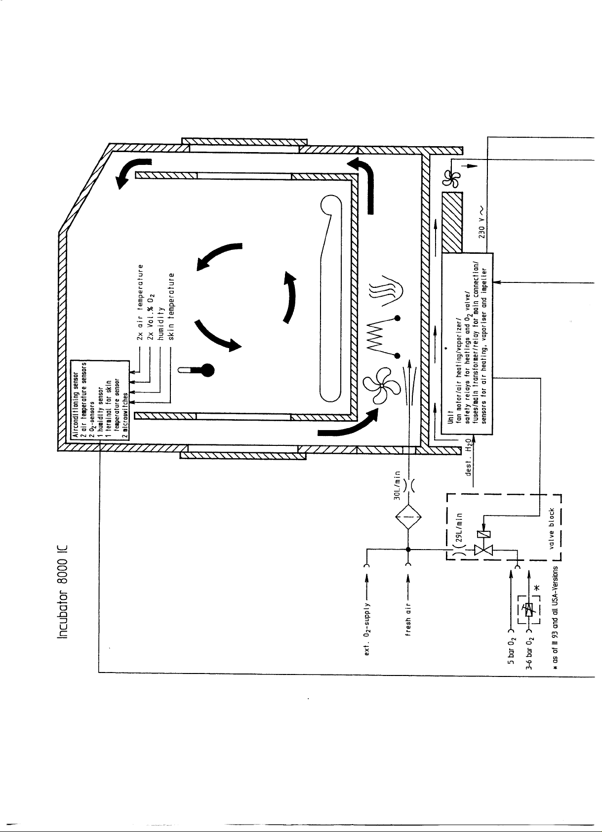
A special airflow system has been developed for the Incubator 8000 series. This system routes
heated air between the double walls on the entire front (hinged front door), over the roof of the
canopy and then draws it down again between the double walls at the rear by means of an
extraction system. Thus the baby lies in an area with very low airflow so that heat loss by
convection is reduced. For the Incubator 8000 SC / NC the double walls at the sides and at the
rear are an option.
the Incubator 8000 IC / SC / NC
The all-round double wall design of the Incubator 8000 series canopy also reduces the loss of
body heat by radiation. When the hinged front door and the hand port doors are open, there is
still an effective hot air curtain which prevents appreciable cooling inside the canopy.
A new type of mattress gives very low heat loss by conduction through the bed, resulting in a
high level of comfort for the baby. It is made of a particularly soft foam plastic, smoothly
encased in film to provide an absolutely hygienic seal.
The incubator is equipped with easy-moving, swivelling castors which permit easy movement
around the hospital. Two of the castors can be locked. There are rails, which can also be used
as handles, on the sides for holding ancillary equipment.
The sensor housing which is located near the baby's head responds very rapidly to changes in
the environment inside the incubator and contributes to a very sensitive control system. The
housing contains the air temperature sensor, the optional oxygen sensor and the optional
relative humidity sensor. It also contains the connection point for the skin temperature sensor
on Incubator 8000 IC units without ThermoMonitoring.
6141.22X Incubator 8000 IC/SC/NC
Function Description
09.99 Page 3 of 49
Page 4

At the Incubator 8000 SC / NC an air temperature sensor located near the baby's head is
attached at the rear of the canopy, the connection point for the skin temperature sensor is
located at the back of the Incubator next to the mains input on units without Thermomonitoring.
The optional oxygen control module on Incubator 8000 IC units permits the required oxygen
concentration within the canopy to be pre-selected and controlled automatically. If the actual
value deviates from the set value, warning signals are given. The control system permits a set
oxygen concentration to be achieved within a very short time (40 % in 1.5 minutes and 60 % in
< 7 minutes). This permits rapid action in emergencies and rapid return to a selected oxygen
concentration after opening the hinged front door or the hand ports.
The humidity control of the Incubator 8000 IC permits a required humidity value to be preselected and maintained. The water required for this is supplied from sterile water bottles.
The humidity supply of the Incubator 8000 SC / NC humidity control can be adjusted in 10
steps.
Evaporation of the water guarantees completely hygieni c air humidification.
In accordance with hygienic requirements, all parts of the Incubator which come into contact
with the gas breathed by the baby can be removed from the basic unit.
The electricall y-operated height adjustment mechanism permits an optimum working height to
be set for both tall and small nurses. In addition, the Incubator can be lowered so that the
nurse can carry out lengthy procedures whilst sitting down, and there is also adequate
legroom beneath it.
The hand port openings have been designed to provide better access for the arms of the
nursing staff than round openings do, yet have a smaller opening cross-section, thus reducing
heat loss.
The incubator is controlled by a microprocessor. The Incubator carries out a general self-test
when it is switched on and automatically every 10 minutes thereafter. This test checks the
various assemblies in the incubator which are crucial to safety by operating them briefly. The
operator is automatically requested to recalibrate the oxygen sensors after switching on the 02
control system and, thereafter, after every 24 hours of operation. Measured value deviations or
system failures are indicated visually and audibly. The heating system and valve are
automatically switched off if operating conditions are outside permitted limits.
The control systems for air temperature, skin temperature and humidity are PI- or PID-controls
and give optimum control.
An additional built-in air-cooler produces rapid cooling as soon as the actual value of the air
temperature is a few tenths of a degree above the set value.
6141.22X Incubator 8000 IC/SC/NC
Function Description
09.99 Page 4 of 49
Page 5

1.2 Safety Features
A self-test is conducted when the incubator is switched on. This involves a test of all memories
in the microprocessor control system and a check to establish whether the various program
segments are running correctly.
The function of actuators, acknowledgement signals, displays and indications is checked by
switching them on and off. For example, the functioning of the fan is checked not by
establishing whether power is reaching the electric motor, but rather by measuring the speed
of rotation directly on the fan. The wiring to peripheral devices is provided i n duplicate.
This complete test is also repeated every 10 minutes during operation.
All options, whether they are activated or not, are tested. An error message is thus indicated
for a faulty module even if it is switched off. This ensures that the operator i s always fully
aware of the actual condition of the incubator.
When the incubator is switched on again, or when a module is switched on, the relevant
required value is set to "starti ng value". The set value displ ay then flashes requesting
confirmation or modification of this value. The actual value indication is displayed alternately
with the prompt "SET" (not humidity Inc. 8000 SC / NC).
1.3 Alarms
The incubator has a graduated system of alarm signals. Faults which occur are signalled in
order of importance. If a non-essential option fails, it does not mean that the incubator has to
discontinue any functions which are of vital importance. The set value deviation and water
shortage alarms are signalled by an intermittent warning tone which can be suppressed for 10
minutes. Faults which entail greater potential danger are signalled by a continuous tone which
cannot be silenced. In addition, the relevant warning LEDs flash to enable the operator to
locate the fault rapidly. The alarm signals are described in detai l below.
1.3.1 Alarm for set value deviations and water shortage
Deviations outside the set l imits for oxygen concentration (> 5 % by Vol. 02), skin temperature
(> 0.5 °C with software version 10.n or 20.n and > 1.0 °C with software version 11.n and 21.n
on us units only) and air temperature (> 1.5 °C), in addition to over-temperature (> 38 °c or >
39.9 °C) and water shortage result in the following alarm signals:
- The actual value display of the relevant control module flashes.
- The specific alarm LED flashes.
- Intermittent alarm tone sounds (can be suppressed for 10 min.).
- The central alarm LED flashes (if available).
6141.22X Incubator 8000 IC/SC/NC
Function Description
09.99 Page 5 of 49
Page 6

The alarm tone for set value difference - 1.5 °C air temperature - is suppressed automatically
for 30 minutes when the incubator is switched on to avoid a continuous alarm signal sounding
during the warming-up phase.
The "Reset" warning button for over-temperature has to be reset by the operator to ensure full
awareness of the error. All other alarms are reset automatically when the relevant conditions
have returned to normal.
If an alarm has been suppressed, the red alarm LED, which had previously flashed, stays
alight but is constant, and a yellow LED indicator above the switch-off button indicates the
switched-off mode. If another alarm occurs when alarms are suppressed, the audible alarm is
re-activated immediately. Depending on the type of fault, this later alarm can be suppressed
again. The period for automatic reactivation of the first al arm tone is then prolonged by the
time interval between the two alarms.
1.3.2 Sensor alarms and fan failure alarm
Faults in the sensors for oxygen, skin temperature, humidity, air temperature and failure of the
fan produce the following alarm signals:
- Three dashes ("---") flash on the relevant actual value displ ay.
- The actual air temperature value flashes in the event of fan failure.
- The specific alarm LED flashes. 0 Continuous alarm tone (non-suppressible)
- The central alarm LED flashes (if available).
Where there have been sensor warnings for oxygen concentration or relative humidity and the
relevant module has been switched off, the incubator can continue to operate with the other
functions. The same applies when there is a skin temperature control alarm, though, in this
case, the faulty sensor must be removed.
1.3.3 Module faults
Alarms for faults in the control modules for oxygen concentration, skin temperature and
relative humidity produce the follo wing alarm signals:
- The letters "Err" (= Error) appear on the relevant actual value display, flashing if the
module is switched on and not flashing if the module is switched off.
- The red "Inop" LED is lit when the module is switched on.
- Continuous alarm tone (non-suppressible) if the module is switched on.
The functions of the other modules which are operating correctly are retained. The operator
can carry on using the incubator after the faulty module has been switched off.
6141.22X Incubator 8000 IC/SC/NC
Function Description
09.99 Page 6 of 49
Page 7

1.3.4 Total shutdown
Faults in the central microprocessor control system and in the air temperature control module
result in complete shutdown of the incubator. The following alarm signals are then given:
- Red "inop" LED is lit.
- Continuous alarm tone (non-suppressible).
Individual checks should be carried out to determine whether the fault appeared only
temporarily. If the incubator shows the "Inop" signal after it is switched on again, i t is
inoperative. It must not be used and must be clearly marked faulty.
2 Functional description of Incubator 8000 IC / SC / NC
2.1 Description of component block diagram
- Component block diagram 8000 IC
- Component block diagram 8000 SC / NC
- Fresh air intake and 02- s upply
- Unit wi t h air heating, f an and hum idifi er
- Electronics module
- Climate sensor (Inc. 8000 I C only)
- Air temperature sensor (Inc. 8000 SC / NC)
Height adjus tment
-
2.1.1 Component block diagram 8000 IC
6141.22X Incubator 8000 IC/SC/NC
Function Description
09.99 Page 7 of 49
Page 8
Page 9
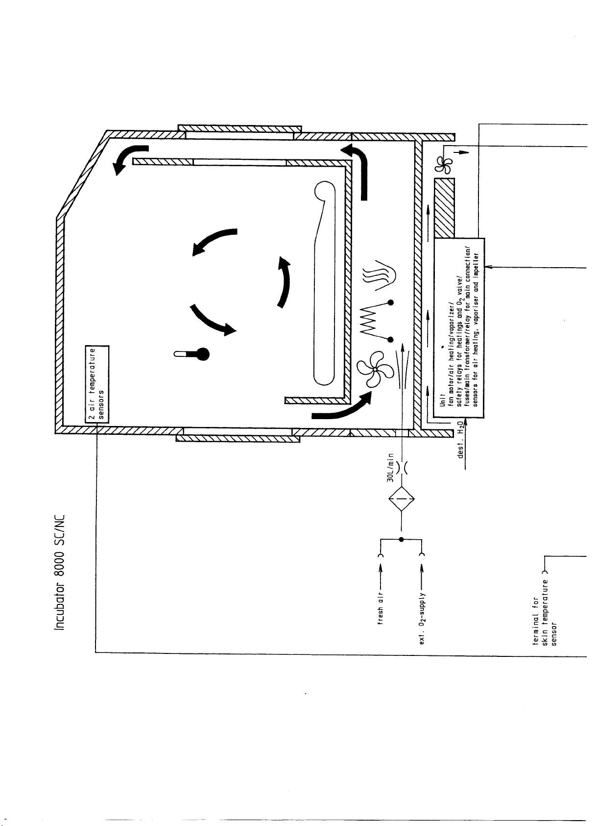
Page 10

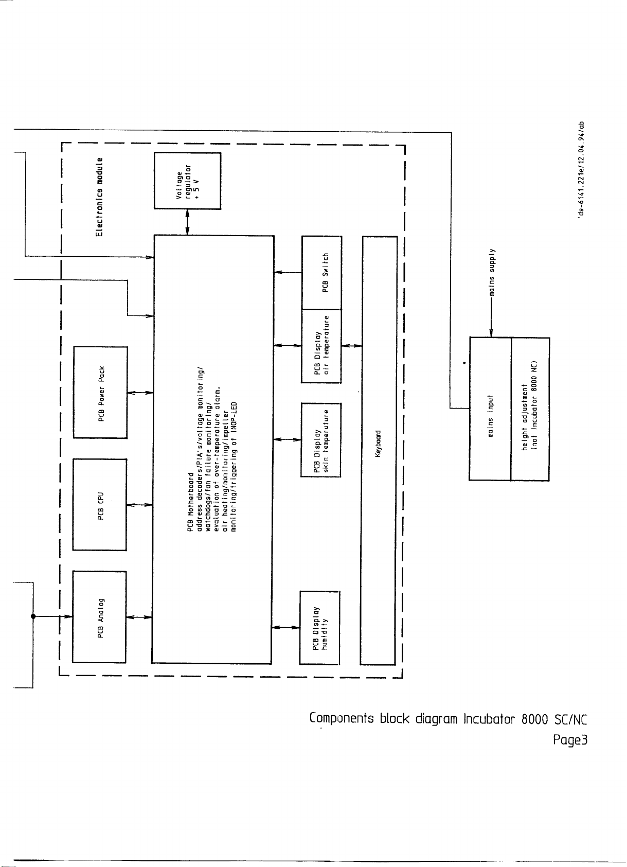
2.1.2 Component block diagram 8000 SC / NC
6141.22X Incubator 8000 IC/SC/NC
Function Description
09.99 Page 10 of 49
Page 11
Page 12
Page 13

2.1.3 Fresh air intake and O2 supply
2.1.3.1 Fresh air intake
Through a fresh air filter 84 02 926 at the back of the Incubator 30 L/min fresh air are taken in
by dosing via the running i mpeller.
2.1.3.2 O2 supply
Incubator 8000 IC:
There are two possibilities for 02 supply in Incubator 8000 IC:
a. External 02-supply
b. Oxygen control
Incubator 8000 SC / NC:
With Incubator 8000 SC / NC only external 02-supply (a.) is possible.
a. external O2 supply
Via a socket oxygen can be supplied to the Incubator through a flowmeter. According to
specification the oxygen concentration has to be monitored with an additional oxygen
measuring instrument with upper and lower alarm limit.
b. oxygen control
An automatic control can be carried out with the integrated 02 concentration control. According
to set value deviation one valve with 29 L/min is opened by the electronic control. According to
specification the oxygen is supplied via the fresh air filter to the patient room.
2.1.4 Heating unit
The following function bl ocks are on the unit:
- fan motor
- air heating with over-temperature fusing
- humidifier with over-temperature fusing
- mains transformer
- auxiliary mains transformer for mains connection
- semiconductor relay for air heating and humidifier
- safety relay for heatings and 02 valves
- Sensor for monitoring of:
the air heating (I/U converter)
the vaporizer (temperature for water shortage alarm)
the impeller (fan)
- fuses for the mains input and the internal
supply voltages
6141.22X Incubator 8000 IC/SC/NC
Function Description
09.99 Page 13 of 49
Page 14

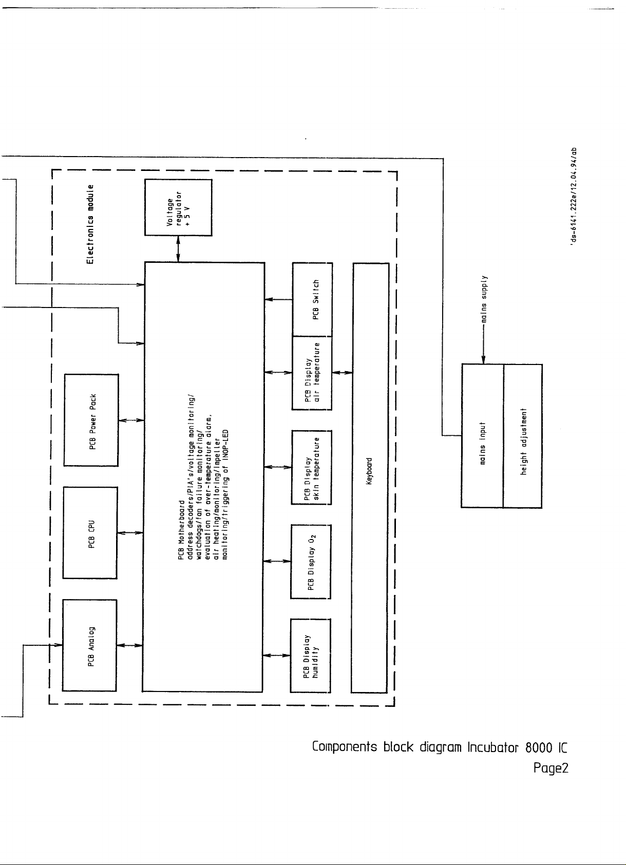
2.1.5 Electronics module
The electronics module comprises the following function blocks:
- keyboard
- PCB Display Air Temperature:
a. triggering of displ ay elements for air temperature control
b. read-out of keyboard
- PCB Display Options and PCB Display Humidity/Skin Temperature:
triggering of the individual display elements of the options
- PCB CPU:
a. processor 6802
b. EPROM
c. RAM with internal battery for data backup
d. timer
e. watchdog
- PCB Analog
a. reading in of measured values of climate sensor housing (Inc. 8000 IC) or of
air temperature sensor (Inc. 8000 SC / NC)
b. reading in of climate sensor housing position (Inc. 8000 IC)
c. processor-dependent monitoring circuit for over-temperature and existence of oxygen
sensors
d. processor-dependent monitoring circuit forpresence of oxygen sensors (Inc. 8000 IC)
- PCB Power Pack
a. Rectification of supply voltage +15 V and -15 V
b. Rectification and control of supply voltage +5 V. The voltage regulator is positioned on
the right hand side panel of the electronics module.
c. Charaino circuit for battery of the mains failure-alarm.
d. Trigger circuit for horn and mains failure LED
e. Horn
- Motherboard
a. Address decoder for peripherals
b. PIAs for triggering of peripherals
c. Evaluation of over-temperature alarm
d. Fan failure monitoring
e. Watchdogs
f. Voltage monitoring
g. Evaluation of air heating monitoring
h. Evaluation of impeller monitoring
6141.22X Incubator 8000 IC/SC/NC
Function Description
09.99 Page 14 of 49
Page 15

i. Evaluation of valve monitoring
j. Triggering of INOP-LED
k. Triggering of additi onal fan
2.1.6 Climate sensor housing (Inc. 8000 IC)
This s ens or detects the cl imatic conditions i ns ide the incubator . For calibration of t he 02
measurement function the sensor can be s wung out of t he incubator int er ior.
Function blocks:
- 2 air temperature sensors
- 2 02 sensors
- Terminal f or s k in temperature sens or ( units with soft ware version 20. n only)
- Humidity sens or with eval uation electr onics
2 micro switches to determine sensor pos ition
-
2.1.7 Air temperature sensor (Inc. 8000 SC / NC)
For measurement of the air temper ature tw o identical s ens or s ar e enc losed in one housing.
2.1.8 Height adjustment
The height is adjusted via an Electro-motor with spindle. The pedestal is triggered via a footoperated switch. The Electro-motor is equipped with an automatically resettable overtemperature switch.
2.2. Description of block diagram of electronic functioning
2.2.1 Incubator 8000 IC / SC / NC block diagrams
6141.22X Incubator 8000 IC/SC/NC
Function Description
09.99 Page 15 of 49
Page 16

Page 17

Page 18

Page 19

Page 20

2.2.2 Detailed description of block diagram
The numbers in brackets refer to the position in the bloc k diagram.
2.2.2.1 Air temperature sensor (39)
The air temperature sensor is part of the feedback loop of an operational amplifier (31B). This
operational amplifier produces an output voltage proporti onal to the air temperature. A second
amplifier stage modifies the voltage to the input voltage range of the ADC. Resolution: 0.0 °C
to 60.0 °C = 0.0 to 5.0 V.
2.2.2.2 Over-temperature sensor (38)
The over-temperature sensor is mechanically i ntegrated with the air temperature sensor in one
housing. This allows a redundant measurement for the air temperature. The amplification
factor and thus the output signal differs from the output signal of the air temperature sensor.
The air and over-temperature sensor are checked crosswise by software. In case of a
temperature difference of more than 0.5 °C a sensor alarm is produced. The over-temperature
sensor is placed in the feedback loop of the operational amplifier (31A). A second amplifier
stage modifies the voltage to the input voltage range of the ADC. Resolution: 0.0 to 50.0 °C =
0.0 to 5.0 V.
2.2.2.3 Over-temperature comparator (29)
The output voltage of the over-temperature sensor circuit is additionally monitored by a
comparator. The trigger level of this comparator is set to 40.0 °C. If the over-temperature
sensor output voltage reaches this li mit independent and unaffected by the microprocessor
this comparator switches off the heater and sets the incubator into the safe operation mode.
The over-temperature condition is stored and latched by a bipolar rel ay (16). After the
temperature has fallen and the over-temperature sensor circuit is reset by the operator with a
dedicated reset button, normal operation of the temperature control system is continued.
2.2.2.4 Testing of over-temperature comparator (36)
Every 10 minutes the over-temperature sensor circuit (comparator) is tested by the
microprocessor. On the Analog PCB the relay (K2) or by FET transistors on newer devices as
of 1996 substitutes for a short time the over-temperature sensor with a fixed resistor simulating
a temperature higher than 40.0 °C.
6141.22X Incubator 8000 IC/SC/NC
Function Description
09.99 Page 20 of 49
Page 21

2.2.2.5 Skin temperature sensor (40)
The circuit for the skin temperature sensor (operational amplifier, block 32) is similar to the air
temperature sensor circuitry.
Software version 10.n and 20.n:
The temperature of 32.0 to 39.0 °C is represented by 0.0 to 5.0 V input voltage of the ADC.
Software version 11.n and 21.n (units with ThermoMonitoring):
The temperature of 30.0 to 42.0 °C is represented by 0.0 to 5.0 V input voltage of the ADC.
2.2.2.6 Testing of the skin temperature sensor circuit (37)
The accuracy of the skin temperature sensor circuitry is checked every 10 minutes as part of
the 10 minute test. On the Analog PCB the relay K1 or by FET transistors on newer devices as
of 1996 replaces software controlled the sensor for a short time with a fixed precision resistor
with the temperature equivalent of 36.0 °C. If this reference temperature is measured with an
error of more than 0.3 °C, a sensor alarm (Err) is caused.
In addition to the automatic accuracy test of the skin temperature sensor measurement, the
operator can manually test the circuit by pressing the "Check 36 °C" key. This procedure in the
same manner replaces the skin temperature sensor with the reference resistor by means of
relay K1 or FET transistors. The operator can look for the correct display of 36 °C.
In order to detect a defective relay K1 or FET transistors which could cause a complete
corrupted skin temperature measurement and control because of the fixed reference resistor a
software test routine is implemented. This routine analyzes the skin temperature sensor data
and makes a plausibility test. The basic assumption is that the reference resistor will lead to a
very stable temperature value with virtually no drift. If, i n a 20 minute time interval, the
temperature drift is less than 0.003 °C it is assumed that the reference resistor is measured
instead of the skin temperature sensor. A sensor failure alarm (Err) will then be generated.
2.2.2.7 Skin temperature sensor alarm (32)
The output voltage (proportional to temperature) of the first amplifier stage is compared for
values that are outside the allowed range of temperature values. This could be caused by a
short circuit in the probe or a broken sensor cable.
2.2.2.8 Skin temperature sensor detection
Software version 10.n and 20.n: The plug of the skin temperature probe is coded in order to
indicate that the sensor is pl ugged in. A 5 V pull up resistor is connected to ground by a
6141.22X Incubator 8000 IC/SC/NC
Function Description
09.99 Page 21 of 49
Page 22

jumper in the plug whenever the sensor is plugged i n. This voltage is sensed by the
microprocessor via a port.
2.2.2.9 Oxygen sensor A (41A), Inc. 8000 IC only
The output voltage of the oxygen sensor cell A is adapted to the ADC by the input amplifier
stage (33A). The output voltage of 0.0 mV to 120 mV is amplified to 0.0 V to 4.76 V.
2.2.2.10 Oxygen sensor B (41B), Inc. 8000 IC only
The output voltage of the oxygen sensor cell B is adapted to the ADC by the input amplifier
stage (33B). Its amplification factor is reduced by the factor of 2.75 compared to the oxygen
sensor A. This different amplification factor is later compensated for by software. After analog
to digital conversion comparing signal B to the signal of oxygen cell A has to show the
discrepancy in values to be within a certain window. Errors because of false addressing of the
multiplexer are clearly detected. Resolution: 0.0 mV to 120 mV input voltage = 0.0 V to
1.73 V output voltage
2.2.2.11 O2 comparators (30A and 30B), Inc. 8000 IC only
In addition to the microprocessor controlled check of the oxygen cell each cell is monitored
with an individual comparator. These comparators are set to a trigger level of approx. 7 mV. If
the output voltage falls bel ow this l imit, the relay (18)and the oxygen valve (3) are switched off
and the oxygen sensor alarm is activated.
2.2.2.12 Detection of sensor head position (43), Inc. 8000 IC only
The position of the sensor housing at the hinge is sensed by two micro switches installed in
the sensor housing and is evaluated via a PIA on the Motherboard PCB.
2.2.2.13 Humidity sensor (42), Inc. 8000 IC only
The output voltage of the humidity sensor is switched to the ADC via a voltage divider (34).
Resolution: 0 to 100 % relative humidity = 0.55 to 4.31 V
6141.22X Incubator 8000 IC/SC/NC
Function Description
09.99 Page 22 of 49
Page 23

2.2.2.14 Reference for ADC (35)
The reference voltage for the ADC is based on the +15 V and the -15 V supply voltage for the
analog components. This allows monitoring the accuracy and function of the voltage regulators
for these voltages.
2.2.2.15 Multiplexer (28)
The eight to one multiplexer selects the input signals for the ADC and is addressed by the
outputs of the PIA. The addressing of the multiplexer is also reread by the PIA to detect
addressing errors. Any addressing error will lead to an Inop alarm.
2.2.2.16 A/D Converter (27)
The A/D converter digitizes the analog signals with a resolution of 12 bit. The 12 bit words are
read by two consecutive 8 bit data readings.
2.2.2.17 Over-temperature alarm (16)
Any over-temperature that is detected either by the microprocessor or by the redundant
hardware is stored in the bistable relay and drives the relay (12) to switch off the heaters. The
hardware detection is set to the trigger level of 40 °C, the software trigger level is set to 38 °C
for set point values less than 37 °C and 40 °C otherwise. One contact of the bistabl e relay is
used for monitoring of the sensor module position by the microprocessor through PIA 1. The
second contact drives the power relay (12) that switches power on and off in the heating
elements for air (1) and water (2). The bistable relay is reset by the microprocessor through
one output of the PIA. This output signal is AC-coupled with a capacitor thus preventing the
bistable relay from locking i n case of a defective output port of the PIA.
2.2.2.18 Fan failure alarm (6)
The rotation of the fan wheel is detected by two permanent magnets in the wheel that induce
pulses into a coil. These pulses are used to re-trigger a mono stable flip-fl op. Its output is read
by the microprocessor through PIA2. If the speed of the fan wheel falls below a certain limit,
the mono stable flip-flop will not be re-triggered in time and the output will go to the high level.
The function of this fan wheel monitoring circuit i s tested by the microprocessor via PIA2. The
microprocessor can purposely suppress the fan wheel pulses in-order to generate a fan wheel
rpm failure signal.
6141.22X Incubator 8000 IC/SC/NC
Function Description
09.99 Page 23 of 49
Page 24

2.2.2.19 Watchdog circuits (21)
Two watchdog circuits are used to supervise the program flow in the microprocessor. The
watchdogs are basically mono stable flip-flops that require to be re-triggered in a certain time
to allow normal operation of the Incubator. One of the watchdogs is triggered by the interrupt
driven routines, the other is triggered by the background software loop. Each of the watchdogs
is addressed by one unique address and is dimensioned to elapse in 100 ms. The software is
designed in a way that both watchdogs are re-triggered in time. Any hardware or software
failure would affect the proper re-triggering and therefore cause one or both watchdogs to be
activated. The outputs of the two mono stable flip-flops are combined and connected to all
relevant power drivers in order to deactivate any actuator thus transferring the incubator into
the safe mode. The signal transducer (22) is also activated independent of the software. The
watchdog mono stable flip-flops are tested in the 10-Minute-Test.
2.2.2.20 +5 V voltage monitoring (19)
The digital suppl y voltage of 5 V is monitored by a window comparator for high and low voltage
conditions. The limits are set to 4.4 V and 5.5. V. If the window comparator senses high or low
voltage, the 24 V power supply for the solid state relays and the oxygen valves is interrupted
by the relay (17). Via transistors V15 and V16 the comparator limits to test the function of the
voltage monitoring can be adjusted. This is done by the software via ports CA2 and CB2 of PIA
S1 (10-Minutes-Test).
Normal operation: CA2 = L-level; CB2 = H-level
Test upper limit: CA2 = H-level; CB2 = H-level
Test lower limit: CA2 = L-level; CB2 = L-level
The +5 V supply voltage is also monitored via a watchdog circuit (25A) on the CPU PCB (25).
This watchdog circuit cannot be tested during operation because it triggers a reset.
2.2.2.21 Driving the actuators
Both air heater and humidifier are digitally controlled through the PIA1 and the solid state
relays (13) and (14). The driver signal for the humidifier is read back by PIA2. The valve (Inc.
8000 IC only) is controlled by PIA1 and driven by a power transistor on the Motherboard PCB.
The driver signal i s supervised by the second PIA.
2.2.2.22 Monitoring of air heating
The driver and status of the air heating are monitored by an insulated current sensor at the
secondary side of high voltage. The output signal is monitored via PIA2.
6141.22X Incubator 8000 IC/SC/NC
Function Description
09.99 Page 24 of 49
Page 25

2.2.2.23 Thermal switches heaters
The air heater is protected by a thermal circuit breaker (9) that interrupts the power for the
heater in case of over-temperatures. The humidifier is equipped with two thermal switches.
One is used to interrupt the power (10) in case of severe overheating. The second thermal
switch (7) operating at a lower temperature level is used to indicate the microprocessor that
the water supply is empty which causes a rise in the temperature of the humidifier.
2.2.2.24 Display driver and keyboard interface (26)
The 7 segment display and the LED's are driven by special integrated circuits which are used
in every module. The keyboard interface of the Air Temperature Display PCB is part of one of
these circuits and reads all keys (button switches) from all modules.
2.2.2.25 Mono stable flip-flop for INOP LED (24)
The Inop LED is driven by a mono stable flip-flop with a time constant of 100 ms. This mono
stable flip-fl op is addressed by the unique address during the background routine.
2.2.2.26 Power supply and battery (15)
The power supply delivers voltages of +5 V, +15 V, -15 V and +24 V. A NiCad battery
integrated into the power supply serves as the power source in case of power failure to drive
the signal transducer and the power failure LED.
2.2.2.27 Power fail detection (23)
If half waves of the AC power supply voltage are missing because of disturbances or
interruptions or because the Incubator has been switched off at the main power switch, a NMI
(Non Maskable Interrupt) is activated. The software will immediately check the position of the
main power switch and based on its positi on initiate a "col d" or "warm" start.
2.2.2.28 Driver for the beeper (22)
The beeper is driven by a digital signal of PIA1. Very short pulses to the beeper are
suppressed by a filter to avoid spurious noise during testing. In case of a power failure the
beeper is activated independentl y of the microprocessor and powered by the battery.
6141.22X Incubator 8000 IC/SC/NC
Function Description
09.99 Page 25 of 49
Page 26

2.2.2.29 Power on (11)
The power switch controls the supply voltage for the mains power relay K1 and K5. The supply
voltage is generated by a small auxiliary transformer.
2.2.2.30 Fan for
In order to shorten the time required for cooling down the Incubator an additional fan placed in
the electronics is acti vated by air heater feedback signal. These pul ses are used for retriggering a mono stable flip-flop. The fan is on whenever the air heater is shut off.
additional cooling
(44
)
2.3 Description of safety facilities
2.3.1 Alarm display
The incubator features a graded alarm behavior. Faults occurring are indicated as a function
of their signifi cance. The alarms for set value deviations, over-temperature and water shortage
feature an intermittent alarm tone which can be deactivated for 10 minutes. All other faults are
signalled by a continuous tone which cannot be silenced. In addition the corresponding alarm
LED flash. Each individual alarm likewise leads to an indication on the central alarm LED (not
available on Incubator 8000 SC / NC with software version 10.n).
2.3.1.1 Alarms in the event of set value deviations, over-temperature and
water shortage
- Actual value display or desired value display humidity Inc. 8000 SC / NC of module
concerned flashes.
- The corresponding alarm LED flashes.
- Intermittent alarm tone (can be deactivated for 10 min).
The alarm tone for the set value/actual value difference > -1.5 °C air temperature is
suppressed automatically for 30 minutes following switch-on of the Incubator. If during this
period the actual value is at least 1.5 °C below the set value, the alarm and the current
suppression time are indicated by the corresponding LED. In this case the actual value display
does not flash. The alarm suppression time is reset prematurely as soon as the actual air
temperature value is no longer 1.5 °C below the set value.
The over-temperature alarm is stored by means of a bipolar relay and must be reset with the
reset button after termination of the over-temperature status. All other alarms are reset
automatically once the cause of the fault has been eliminated.
6141.22X Incubator 8000 IC/SC/NC
Function Description
09.99 Page 26 of 49
Page 27

In the event of suppressed audio alarm, the corresponding alarm LED and the central alarm
LED (not available on Incubator 8000 SC / NC with software version 10.n) light up
continuously; the horn is off. The yellow LED above the switch-off button indicates that the
alarm has been acknowledged.
Should a further alarm situation occur during the course of alarm suppression, the audio alarm
is immediately re-activated and the alarm suppression time reset. Depending on the type of
fault, this alarm can also be suppressed again. The reactivation time for the first alarm tone is
then extended by the difference in time between the two alarms.
2.3.1.2 Sensor alarms, fan failure alarm
Faults in the sensors for air temperature, skin temperature, oxygen concentration (Inc. 8000 IC
only) and humidity (Inc. 8000 SC / IC only) as well as fan faults result in the following alarm
messages:
- Three dashes (air and skin temperature) or two dashes (02, humidity) flash in the
respective actual value display.
- In the event of a fan fault the air temperature actual value flashes.
- The corresponding alarm LED flashes.
- Continuous horn tone (cannot be deactivated).
With respect to the sensor alarms for oxygen concentration (Inc. 8000 IC only) and humidity
(Inc. 8000 IC only), the alarm is reset following switch-off of the module concerned and further
operation can be continued with the other functions. The same applies to the skin temperature
module, however, the defective sensor must first be removed in this case.
2.3.1.3 Module fault
Hardware faults affecting a single module result in the fol lowing alarm messages for the skin
temperature, oxygen concentration and humidity modules:
- The letters "Err" flash up on the corresponding actual or desired value display if the module
is switched on or appear in steady form if the module is switched off.
- INOP-LED lights up if module is switched on.
- Continuous horn tone (cannot be deactivated) if module is switched on.
The functions of the other modules which are working properly are retained.
6141.22X Incubator 8000 IC/SC/NC
Function Description
09.99 Page 27 of 49
Page 28

2.3.1.4 INOP
Serious hardware or software faults result in complete failure of the incubator. The following
alarm messages are given:
- The INOP-LED lights.
- Continuous horn tone (cannot be deactivated).
The equipment is not serviceable.
Additional for Incubator 8000 IC:
If after switch-off of the 02 module within a few minutes an increase of the 02 concentration by
more than 3 Vol. by. % is detected this will also lead to an INOP message:
- INOP-LED lights.
- Continuous horn tone (cannot be deactivated).
The current 02-actual value is di splayed flashing.
2.3.2 Software
All software routines described below (except test for RAM battery backup) that detect a failure
condition will cause an INOP alarm.
2.3.2.1 RAM test
After power is turned on, a complete test of the RAM (Random Access Memory) addressing
range of the microprocessor is performed. Specific bit patterns are used and move through the
RAM area. All RAM cells that are not used by the software are set to zero. During normal
operation of the software an ongoing RAM test is performed in the background. During this test
blocks of the RAM are swapped into a reserved RAM area. The RAM is then tested with the bit
patterns test scheme. All data transfer from and to the data block under test is secured by
CRC-calculations ( Cyclic Redundancy Check).
2.3.2.2 Test of RAM Battery Backup
After power is turned on, the battery backed up RAM is checked by analyzing the contents of 5
test addresses. If a mismatch was detected, the continuous tone appears for approximately 4
seconds. Then the test addresses are rewritten with the proper information and a cold start is
performed which does not rely on the corrupted data in the battery backed up RAM.
6141.22X Incubator 8000 IC/SC/NC
Function Description
09.99 Page 28 of 49
Page 29

2.3.2.3 ROM Test
After power is on the signature of the ROM (Ready Only Memory) is tested by calculating the
checksum (CRC). During normal operation an ongoing ROM test is performed in background.
Approximately every 5 minutes the whole ROM contents is tested completely. The ROM cell
contents is tested for non-equivalence by EXOR operations.
2.3.2.4 Timer Test
After power is on, the timers are programmed to a certain time. The operation of the timers is
then compared with a software timer that consists of a program loop.
2.3.2.5 PIA Test
The PIA (Peripheral Interface Adapter) initialization is checked upon "power on" as part of the
self check routines.
2.3.2.6 Display Test
The internal RAM of the display and keyboard control IC (Integrated Circuit) is reread after
every writing of new data into the chip. That read data is then compared with the original data.
2.3.2.7 CPU Test
The test of the CPU (Central Processing Unit) is performed automatically by the two cyclically
executed routines for RAM test and 16 bit CRC calculation and by the logical program tracing.
2.3.2.8 Logical Program Tracing
All program execution, whether interrupt driven or part of the background loop, is supervised
by the logical program tracing scheme. Before every return of a subroutine, specific alterations
of data in a special data area by using all CPU-commands and addressing modes are
performed. Only when the predicted program flow is followed properly, these data
manipulations will lead to the correct results which are supervised. If, because of a hardware
or software failure, the program flow is affected, the logical program sequence is changed and
will be detected as being incorrect by the logical program tracing scheme.
6141.22X Incubator 8000 IC/SC/NC
Function Description
09.99 Page 29 of 49
Page 30

2.3.2.9 10 Minute Test
The 10 minute test is implemented to test every 10 minutes all testable hardware safety
functions.
3 Detailed description of Incubator 8000 IC / SC / NC sub-assemblies
- Heating unit
- Electronics module:
a. Keyboard
b. PCB Display Air Temperature
c. PCB Display Options
d. PCB Display Humidity (only Inc. 8000 SC)
e. PCB CPU
f. PCB Analog
g. PCB Power Pack
h. PCB Motherboard
i. PCB Switch
j. PCB Fan
k. Voltage regulator on side panel
l. PCB Filter
- Air temperature sensor (only Inc. 8000 SC / NC)
- Environmental sensor housing (only Inc. 8000 IC)
- Skin temperature sensor
- Valve block (only Inc. 8000 IC)
3.1
- The following function bl ocks may be found on the unit:
- Fan motor
- Air heating with over-temperature protection (unsoldering protection)
- Humidifier with over-temperature protection (manually re-settable)
Heating unit
6141.22X Incubator 8000 IC/SC/NC
Function Description
09.99 Page 30 of 49
Page 31

- Mains transformer
- Sensor to monitor number of revolutions at impeller (inductive fan monitoring)
- Semiconductor relay for galvanically separated triggering of air heating and humidifier
- PCB Unit:
a. mains auxiliary transformer for mains connection
a. mains connection relays
b. safety relays for heatings and O2 valves
c. fuses for mains input and internal supply vol tages
The unit forms the intersection between supply voltage and secondary side of the electronics.
A voltage higher than + 33 V is not supplied to the other incubator components.
3.1.1 Detailed description of function blocks of Unit PCB
3.1.1.1 Mains connection
Incubator 8000 is connected to the mains via the auxiliary transformer L1 to which the mains
relays K1 and K5 are connected at the secondary to +12 V. The relay is connected via pins
X1/1 and X1/27 via the standby switch at the front panel. Through the relay contacts the mains
voltage is suppli ed to the consumers.
3.1.1.2 Cutoff relay K2 for heating
Relay K2 is a safety relay to cut off the mains voltage supply of the ai r and humidifier heating.
3.1.1.3 Cutoff relay K3 for 02 valves (Inc. 8000 IC only)
Relay K3 is a safety relay to cut off the supply voltage of the 02 valves.
3.1.1.4 Cutoff relay K4 for +24 V
Relay K4 is a safety relay to cut off simultaneously the supply voltage of the semiconductor
relays, of the air and humidifier heating and of the 02 valves.
6141.22X Incubator 8000 IC/SC/NC
Function Description
09.99 Page 31 of 49
Page 32

3.1.1.5 24 V supply voltage
The 24 V a.c. voltage at TP22 and TP23 supplies the fan motor via TP30 to TP33. Moreover,
this a.c. voltage is rectified on the Unit PCB and supplies voltage to the semiconductor relays,
the 02 valves and the safety relays.
3.2 Electronics Module
The electronics modules are a sub-assembly to control the air temperature, the 02
concentration (Inc. 8000 IC only) and the humidity. The skin temperature module also
facilitates control of the air temperature in dependence of a child's skin temperature. The
electronics module comprises the following function blocks:
- Keyboard
- Display Air Temperature PCB
- Display PCB (skin temperature with SW 10.n and 20.n, 02-control, humidity control Inc.
8000 IC)
- Display Humidity PCB (only Inc. 8000 SC / NC))
- CPU PCB
- Analog PCB
- Power Pack PCB
- Motherboard PCB
- Switch PCB
- 5 V voltage regulator
- Display Skin PCB (as of SW 11.n and 21.n)
3.2.1 Keyboard
The keypad is evaluated on the PCB Display Air Temperature.
3.2.2 Display Air PCB
The PCB Display Air indicates the set and the actual values, the alarms and operating
conditions for the operating mode air temperature control as well as for the evaluation of the
whole keypad. Furthermore the LEDs which are not related to the module are on this PCB.
3.2.2.1 Keypad and display interface module 8279
The programmable keypad and display interface module 8279 (D1) takes over the display
control of the Display Air PCB as well as the inqui ry of the whole Incubator 8000 keypad. The
display control is done by means of the multiplexer. Ports A0 to A3 and B0 to B3 are driven as
6141.22X Incubator 8000 IC/SC/NC
Function Description
09.99 Page 32 of 49
Page 33

B-Bit channel, via ports SL0 to SL1 and decoder D2 the displays are read in columns. The
keypad inquiry is also done by means of the multiplexer method via ports R0 to R7. Via ports
SL0 to S11 and decoder D2 the column reading of the keypad is carried out.
3.2.2.2 INOP-LED
The INOP-LED V 34 is triggered by an external signal (watchdog PCB Motherboard) via pin
X1/4.
3.2.2.3 Mains failure LED
The mains failure LED (V26) is externally driven via pins X1/19 and X1/21 (Power Pack PCB).
3.2.2.4 Working LED
The working LED V27 is directly connected to the supply voltage +5 V via the series resistor
R15.
3.2.3 Display PCB
3.2.3.1 Display interface module
The programmable keypad and display interface module 8279 (D1) takes over the display
control on the Display PCB. The output is done with the multiplexer method. Ports A0 to A3
and B0 to B3 are driven as 8-bit channel, via ports SL0 to S11 and a decoder the column
reading of the displays is effected.
3.2.3.1 Use of Display PCB
On units with software version 10.n and 20.n:
- O2
- Skin
- Humidity (Inc. 8000 IC only)
On units with software version 11.n and 21.n:
- O2
- Humidity (Inc. 8000 IC only)
6141.22X Incubator 8000 IC/SC/NC
Function Description
09.99 Page 33 of 49
Page 34

3.2.4 Display Humidity PCB (Inc. 8000 SC / NC only)
Functions like PCB Display. On this PCB only the necessary display elements are fitted.
3.2.5 CPU PCB
3.2.5.1 Intended use
The CPU Standard 2 PCB is a sub-assembly which forms the center of electronical driving in
many Drager devices. As of 1993 a CPU Incubator PCB is used in all Incubators 8000 series.
3.2.5.2 Block diagram
Block 1 includes the CPU (UP 6802) with clock oscillator and address decoding.
Block 2 contains the entire data and program storage (up to 64 kByte RAM/EPROM). Wi th
ACIA in block 3 a serial interface is provided but is not fitted for Incubator 8000 series.
6141.22X Incubator 8000 IC/SC/NC
Function Description
09.99 Page 34 of 49
Page 35

TIMER module 4 enables timer functions and may be operated with internal and several
external clock pulses.
A battery-buffered REAL TIME CLOCK 5 provides time and date (not fitted for Incubator 8000
series).
3.2.5.3 Detailed description
The CPU Standard 2 PCB or the CPU Incubator PCB is a microprocessor system featuring the
microprocessor 6802, which contains the entire data and program storage area and various
peripheral modules. Voltage monitoring and watchdog logic are also provided (CPU Standard
2 PCB only).
The address, data and control lines of the CPU are connected to the operating voltage by way
of pull-up resistance networks, so as to obtain le vel matching with respect to the subsequent
HCMOS modules. The address and control li nes are buffered directly at the CPU with D2, D3
and D5 in order to enable the assembly to be operated in DMA mode. These driver modules
are controlled by the signal BA.
The address decoder consists of the programmable module D6 and the subsequent decoder
D7. Chip select signals for the memory modules D8 to D12 and one select signal each for the
internal I/O modules, the external I/O modules and the data bus driver are generated in D6.
The programmability of D6 makes it possible - together with the jumper fields X2 to X5, X8 - to
have extremely flexible assembly with various memory modules. The signal BA at D7 is used
to prevent an external CPU (DMA mode) having memory access to the I/O modules.
The timer module D13 can be operated with an internal and an external clock pulse. One of
the three clock pulses 100 Hz, 1 kHz, 10 kHz can be supplied to each cl ock input C1, C2, C3
via the jumper field X6. The three gate inputs G1, G2. G3 and the timer outputs Q1, QZ, Q3
are routed to the printed circuit board connector X1.
3.2.6 Analog PCB
3.2.6.1 Intended use
Three different versions of the Analog PCB are available:
82 00 770 Without skin temperature measurement
82 00 920 With skin temperature measurement (1 channel). For software version
10.n and 20.n only.
82 90 680 With skin temperature measurement (2 channels for Thermomonitoring).
For software version 11.n and 21.n only.
6141.22X Incubator 8000 IC/SC/NC
Function Description
09.99 Page 35 of 49
Page 36

3.2.6.2 Block diagram
6141.22X Incubator 8000 IC/SC/NC
Function Description
09.99 Page 36 of 49
Page 37

3.2.6.3 Detailed description of function blocks
a. air temperature sensor
b. over-temperature sensor
c. over-temperature comparator
d. test over-temperature comparator
e. skin temperature sensor
f. test skin temperature sensor circuit
g. skin temperature-sensor alarm
h. skin temperature sensor detection
i. 02 sensor A
j. 02 sensor B
k. 02 comparator
l. detection of sensor head position
m. humidity sensor
n. A/D converter reference voltage
o. Multiplexer
p. A/D converter
a. air temperature sensor
The air temperature sensor is part of the feedback loop of an operational amplifier and
supplies an outlet voltage proportional to the temperature which is adapted to the input voltage
range of the A/D converter via a second amplification stage. Resolution: 0.0 °C to 60.0 °C =
0.0 V to 5.0 V.
b. over-temperature sensor
The over-temperature sensor is installed in the same housing as the air temperature sensor
and serves as redundant measuring system for the air temperature. The amplification factor
and thus the output signal is not equal to the output signal of the air temperature sensor. The
air temperature and the over-temperature sensor are monitored by the software. If the
measured temperatures deviate by more than 0.5 °C a sensor alarm is given. The overtemperature sensor is part of the feedback loop of an operational amplifier and supplies an
outlet voltage proportional to the temperature which is adapted to the input voltage range of
the A/D converter via a second amplification stage. Resolution: 0.0 °C to 50.0 °C = 0.0 V to
5.0 V.
c. over-temperature comparator
The output voltage of the over-temperature sensor is additionally evaluated by a comparator
whose response limit is set to 40.0 OC. Independent of the microprocessor system in the event
of over-temperature the heating is switched off via this comparator and thus the device is put
6141.22X Incubator 8000 IC/SC/NC
Function Description
09.99 Page 37 of 49
Page 38

into a safe condition. The over-temperature condition is stored by a bi polar relay on the
Motherboard PCB. The heating control can only be released by acknowledgement via a reset
button after the temperature has fallen below the comparator limit.
d. testing of over-temperature comparator
The function of the over-temperature comparator is checked software-controlled every 10
minutes. On the Analog PCB the relay (K2) or by FET transistors on newer devices as of 1996
substitutes for a short time the over-temperature sensor with a fixed resistor simulating a
temperature higher than 40.0 °C.
e. Skin temperature sensor
The skin temperature sensor is part of the feedback loop of an operational amplifier and
supplies an output voltage proportional to the temperature which is adapted to the input
voltage range of the A/D converter via a second amplification stage.
Software version 10.n and 20.n:
The temperature of 32.0 to 39.0 °C is represented by 0.0 to 5.0 V input voltage of the ADC.
Software version 11.n and 21.n (units with Thermomonitoring):
The temperature of 30.0 to 42.0 °C is represented by 0.0 to 5.0 V input voltage of the ADC.
f. Testing of the skin temperature sensor circuit
The accuracy of the skin temperature sensor circuitry is checked every 10 minutes as part of
the 10 minute test. On the Analog PCB the relay K1 or by FET transistors on newer devices as
of 1996 replaces software controlled the sensor for a short time with a fixed precision resistor
with the temperature equivalent of 36.0 °C. If this reference temperature is measured with an
error of more than 0.3 °C, a sensor alarm (Err) is caused.
In addition to the automatic accuracy test of the skin temperature sensor measurement, the
operator can manually test the circuit by pressing the "Check 36 °C" key. This procedure in the
same manner replaces the skin temperature sensor with the reference resistor by means of
relay K1 or FET transistors. The operator can look for the correct display of 36 °C.
In order to detect a defective relay K1 or FET transistors which could cause a complete
corrupted skin temperature measurement and control because of the fixed reference resistor a
software test routine is implemented. This routine analyzes the skin temperature sensor data
and makes a plausibility test. The basic assumption is that the reference resistor will lead to a
very stable temperature value with virtually no drift. If, i n a 20 minute time interval, the
temperature drift is less than 0.003 °C it is assumed that the reference resistor is measured
instead of the skin temperature sensor. A sensor failure alarm (Err) will then be generated.
6141.22X Incubator 8000 IC/SC/NC
Function Description
09.99 Page 38 of 49
Page 39

g. Skin temperature sensor alarm
The output voltage (proportional to temperature) of the first amplifier stage is compared for
values that are outside the allowed range of temperature values. This could be caused by a
short circuit in the probe or a broken sensor cable.
h. Skin temperature sensor detection
Software version 10.n and 20.n: The plug of the skin temperature probe is coded in order to
indicate that the sensor is pl ugged in. A 5 V pull up resistor is connected to ground by a
jumper in the plug whenever the sensor is plugged i n. This voltage is sensed by the
microprocessor via a port.
i. Oxygen sensor A, Inc. 8000 IC only
The output voltage of the oxygen sensor cell A is adapted to the ADC by the input amplifier
stage (33A). The output voltage of 0.0 mV to 120 mV is amplified to 0.0 V to 4.76 V.
j. Oxygen sensor B, Inc. 8000 IC only
The output voltage of the oxygen sensor cell B is adapted to the ADC by the input amplifier
stage (33B). Its amplification factor is reduced by the factor of 2.75 compared to the oxygen
sensor A. This different amplification factor is later compensated for by software. After analog
to digital conversion comparing signal B to the signal of oxygen cell A has to show the
discrepancy in values to be within a certain window. Errors because of false addressing of the
multiplexer are clearly detected. Resolution: 0.0 mV to 120 mV input voltage = 0.0 V to
1.73 V output voltage
k. O2 comparators, Inc. 8000 IC only
In addition to the microprocessor controlled check of the oxygen cell each cell is monitored
with an individual comparator. These comparators are set to a trigger level of approx. 7 mV. If
the output voltage falls bel ow this l imit, the relay (18)and the oxygen valve (3) are switched off
and the oxygen sensor alarm is activated.
l. Detection of sensor head position, Inc. 8000 IC only
The position of the sensor housing at the hinge is sensed by two micro switches installed in
the sensor housing and is evaluated via a PIA on the Motherboard PCB.
6141.22X Incubator 8000 IC/SC/NC
Function Description
09.99 Page 39 of 49
Page 40

m. Humidity sensor, Inc. 8000 IC only
The output voltage of the humidity sensor is switched to the ADC via a voltage divider (34).
Resolution: 0 to 100 % relative humidity = 0.55 to 4.31 V
n. Reference for ADC
The reference voltage for the ADC is based on the +15 V and the -15 V supply voltage for the
analog components. This allows monitoring the accuracy and function of the voltage regulators
for these voltages.
o. Multiplexer
The eight to one multiplexer selects the input signals for the ADC and is addressed by the
outputs of the PIA. The addressing of the multiplexer is also reread by the PIA to detect
addressing errors. Any addressing error will lead to an Inop alarm.
p. A/D Converter
The A/D converter digitizes the analog signals with a resolution of 12 bit. The 12 bit words are
read by two consecutive 8 bit data readings.
3.2.7 Power Pack PCB
3.2.7.1 Intended use
PCB Power Pack serves the rectification of the suppl y voltages +15 V and -15 V. By means of
half-wave monitoring a power fail or mains interrupt is recognized. If the mains voltage fails a
battery-buffered audible alarm is given by a beeper on the PCB and an optical alarm is given
by an external LED. During operation the beeper is driven by an external signal.
6141.22X Incubator 8000 IC/SC/NC
Function Description
09.99 Page 40 of 49
Page 41

3.2.7.2 Detailed description of function blocks
a. Supply voltage +15 V
b. Supply voltage -15 V
c. Supply voltage +5 V
d. Power-fail recognition
e. Driving of beeper
f. Storage battery charging connection
a. Supply voltage +15 V
The AC-voltage at pins 1 a/c and 2 a/c is rectifi ed, filtered and routed to the +15 V fixed
voltage regulator.
b. Supply voltage -15 V
The AC-voltage at pins 3 a/c and 4 a/c is rectifi ed, filtered and routed to the -15 V fixed voltage
regulator.
c. Supply voltage +5 V
The AC voltage at pins 5/6 a/c and 7/S a/c is rectified, filtered and routed to the 5 V fixed
voltage regulator which is attached outside.
d. Power-fail recognition
The AC-voltage at pins 1 a/c and 2 a/c is processed for triggeri ng of mono flop D1. If a half-
wave fails or when the device is switched off an NM1 is released by the output of the mono.
Via pin 28 a/c the position of the mains switch at the time of the power fail is evaluated and
thus a flag is generated for cold-/warmstart decision for the software after the mains voltage
has returned.
e. triggering of beeper
During operation the beeper is driven vi a pin 24 a/c. The beeper is active when the H-level is
present at this pin. Capacitor C12 and diodes V33 and V34 prevent a short response of the
beeper when the device is switched off. In case of power fail the beeper is fed by the storage
battery via the closed mains switch auxiliary contacts. Via pin 23 a/c an external LED is
switched on.
6141.22X Incubator 8000 IC/SC/NC
Function Description
09.99 Page 41 of 49
Page 42

f. storage battery switching circuit
During operation the storage battery is connected to a charging circuit consisting of R6 to R9
and transistor V23.
3.2.8 Motherboard PCB
3.2.8.1 Intended use
The Motherboard PCB interconnects all PCBs of Incubator 8000 series. Moreover, the
components for the digital signal processing (except CPU) are installed on this PCB.
3.2.8.2 Detailed description of function blocks
a. address decoder
b. PIA
c. over-temperature alarm
d. fan failure alarm
e. watchdogs
f. +5 V voltage monitoring
g. indication air heating
h. monoflop for INOP-LED
i. triggering of additional fan
a. address decoder
Via the address decoders D4 and D5 the CS-signals from the address range 8XXXh are
generated.
b. PIA
PIA D1 is addressed via the addresses 8010h to 8013h, PIA D2 via addresses 8020h to
8023h.
Assignment of PIA Ports D1 (E = input, A = output)
Port Function
PA0 E Indication over-temperature
PA1 E Code skin temperature
PA2 E Code 02
PA3 A Addressing of Multiplexer (A0)
6141.22X Incubator 8000 IC/SC/NC
Function Description
09.99 Page 42 of 49
Page 43

PA4 A Addressing of Multiplexer (A1)
PA5 A Addressing of Multiplexer (A2)
PA6 E Fan interference/failure
PA7 A Addressing Multiplexer
PB0 A Triggering air heating
PB1 A Triggering humidifier heating
PB2 A Triggering 02-valve 1
PB3 A Triggering 02-valve 2 (not used)
PB4 A Reset over-temperature alarm
PB5 A Check 36 °C
PB6 A Relay over-temperature alarm and relay 02-cut-off
PB7 A Beeper
CA1 free
CA2 A Test +5 V voltage monitoring, upper limit
CB1 free
CB2 A Test +5 V voltage monitoring, lower limit
Assignment of PIA Ports D2, E = input, A = output)
Port Function
PA0 E Code humidity
PA1 E Water shortage
PA2 A DW bus, external alarm (not used)
PA3 E Indication addressing of Multiplexer (A0)
PA4 E Indication addressing of Multiplexer (A1)
PA5 E Indication addressing of Multiplexer (A3)
PA6 E Indication Check 36 °C
PA7 E Indication air heating
PB0 E Code of sensor head position, switch 1
PB1 E Indication humidifier heating
PB2 E Indication 02-valve 1
PB3 E Indication 02-valve 2 (not used)
PB4 E Code of sensor head position, switch 2
PB5 A Test over-temperature comparator
PB6 E NMIQ: evaluation of NMI for cold-/warm start
PB7 E Code mains switch on/off
CA1 free
CA2 free
CB1 free
CB2 E Test fan failure alarm
6141.22X Incubator 8000 IC/SC/NC
Function Description
09.99 Page 43 of 49
Page 44

c. over-temperature alarm
The bistable relay for the over-temperature alarm is installed on the Motherboard PCB. The
excitation winding is triggered by the hardware via X2/20c from the PCB Analog and by the
software via port PB6 from PIA D1. By contact K1.l the relay position is read in and evaluated
via port PA0 of PIA D1. Through contact K1.2 a cutoff relay is driven for the actuators.
Excitation of the reset winding is done via port PB4 of PIA D1. C16 prevents continuous driving
of the reset winding due to a defective port PB4 and thus that a a pick up of the relays in the
event of over-temperature is made impossible.
d. fan failure alarm
The fan is monitored by the voltage pulses induced in a coil by two permanent magnets which
are attached at the impeller. The negative pulse triggers the mono flop D6A via the inverting
amplifier N1. Via port PA6 of PIA D1 the signal is evaluated. Via port CB2 of PIA D2 the circuit
function may be tested by pulling down the input of the circuit to a lower voltage level. Thus
the fan pulses become ineffective.
e. watchdogs
Mono flops D3A and D3B form the two watchdogs for driving of the heatings and the valves.
The watchdogs monitor the chronological program flow, separate for background and IRQlevel. Mono D3A is re-triggered via address 8030h in the background, mono D3B via address
8040h in the IRQ. The maximum re-triggering time is 100 ms. Both output signals are
interconnected logically and with a further interconnection of the trigger signals for the
heatings and valves lead to a release resp. blocking of these actuators. Moreover, in case one
of the mono flops is elapsed the beeper is activated independent of the software.
f. +5 V voltage monitoring
The digital suppl y voltage of 5 V is monitored by a window comparator for high and low voltage
conditions. The limits are set to 4.4 V and 5.5. V. If the window comparator senses high or low
voltage, the 24 V power supply for the solid state relays and the oxygen valves is interrupted
by the relay (17). Via transistors V15 and V16 the comparator limits to test the function of the
voltage monitoring can be adjusted. This is done by the software via ports CA2 and CB2 of PIA
S1 (10-Minutes-Test).
Normal operation: CA2 = L-level; CB2 = H-level
Test upper limit: CA2 = H-level; CB2 = H-level
Test lower limit: CA2 = L-level; CB2 = L-level
The +5 V supply voltage is also monitored via a watchdog circuit (25A) on the CPU PCB (25).
This watchdog circuit cannot be tested during operation because it triggers a reset.
6141.22X Incubator 8000 IC/SC/NC
Function Description
09.99 Page 44 of 49
Page 45

g. indication air heatinq
The indication of the air heating connection state is done from the supply voltage side through
a converter on the PCB Unit. With this sinusoidal signal a mono flop connection is re-triggered
and the output signal of PA7 of PIA D2 is evaluated.
h. Mono flop for INOP-LED
Via another monoflop (D6B) the INOP-LED is driven. The time constant is 100 ms. The mono
is re-triggered via address 8050h.
i. triggering of additional fan
A mono-flop is installed on the printed circuit board, which is triggered by the indication
impulses generated by the air heating via the current transformer. Via this mono-flop a fan is
driven as soon as the air heating becomes inactive. The time constant for the mono flop is
1.36 s.
3.2.9 Switch PCB
The standby-switch with three independent switching contacts is install ed on the Switch PCB.
Switching contact S1.1 closes mains relay K1 on the Unit PCB. By means of switching
contacts S1.2 and S1.3 the horn and the mains failure LED - supplied by the storage battery
on the Power Pack PCB - are triggered in the event of power failure.
3.2.10 +5 V voltage regulator
The AC voltage of the transformer of the unit is rectified on the Power Pack PCB and is
stabilized with the 5 V voltage regulator on the right side panel of the electronic module.
6141.22X Incubator 8000 IC/SC/NC
Function Description
09.99 Page 45 of 49
Page 46

3.3 Air temperature sensor Inc. 8000 SC / IC
The air temperature sensor comprises 2 NTCs.
Temperature in °C Resistance in Ohm
20 6246.0
21 5970.8
22 5709.4
23 5460.9
24 5224.7
25 5000.0
26 4786.1
27 4582.5
28 4388.8
29 4204.4
30 4028.7
31 3861.2
32 3701.6
33 3549.6
34 3404.6
35 3266.3
36 3134.4
37 3008.6
38 2888.5
39 2773.9
6141.22X Incubator 8000 IC/SC/NC
Function Description
09.99 Page 46 of 49
Page 47

3.4 Climate sensor housing Inc. 8000 IC
3.4.1 Intended use
The Incubator sensor serves measurement of the climatic conditions inside the
Incubator 8000 IC. The air temperature, 02-concentration and the relative air humidity are
monitored. On units with software version 20.n (without ThermoMonitoring) a skin temperature
sensor may be connected to devices which are equipped accordingly.
3.4.2 Arrangement
3.4.3 Detailed description
3.4.3.1 Temperature sensors
The air temperature sensor comprises 2 NTCs.
Temperature in °C Resistance in Ohm
20 6246.0
21 5970.8
22 5709.4
23 5460.9
6141.22X Incubator 8000 IC/SC/NC
Function Description
09.99 Page 47 of 49
Page 48

24 5224.7
25 5000.0
26 4786.1
27 4582.5
28 4388.8
29 4204.4
30 4028.7
31 3861.2
32 3701.6
33 3549.6
34 3404.6
35 3266.3
36 3134.4
37 3008.6
38 2888.5
39 2773.9
3.4.3.2 O2 sensors
There are two independent 02-cells in the climate housing one half of which is evaluated.
The sensor is designed according to the fuel cell principle as double cell, i.e. it is an
electrochemical cell which builds up a voltage due to an ionic current. The cell comprises the
capsule with the electrolytes, the lead anode and the gold cathode with teflon foil.
The oxygen to be measured diffuses through the teflon diaphragm, reacts at the gold cathodes
and produces lead oxide and H20 at the lead anode. During this chemical process an electric
voltage is produced which is proportional to the oxygen partial pressure. The gold cathode is
6141.22X Incubator 8000 IC/SC/NC
Function Description
09.99 Page 48 of 49
Page 49

polarized positive, while the lead anode is negative. Since the lead anode is converted it has
a limited lifetime. The internal resistance is determined by the electrode surface, the oxygen
diffusion rate and the distances. It is also dependent on the sensor lifeti me. In normal
condition it is 700 Ohm. Like most of the chemical processes this one is also dependent on the
temperature. Because of this temperature-independent resistors are connected in parallel to
the sensor which correct the measuring-circuit voltage in conjunction with the internal
resistance.
3.4.3.3 Humidity sensor
In the environmental sensor housing a capacitive humidity sensor with the evaluation
electronics is i n stalled. The output voltage is:
Voltage humidity = (7.1 V / 100 %) x rel. Humidity (%) + 1.05 V
3.4.3.4 Microswitches
The position of the climate sensor housing is evaluated via two microswitches in four positions:
1 sensor housing swivel led in
2 sensor housing partly swivelled in
3 sensor housing hinged
4 sensor housing removed from the hinge
3.5 Skin temperature sensor
The skin temperature sensor is a NTC.
In addition to the recognition "sensor plugged in" a short-circuiting link is installed in the plug
(not used with software version 11.n and 21.n).
T (°C) R (Ohm)
33.0 1588.3
36.0 1411.3
38.0 1293.3
6141.22X Incubator 8000 IC/SC/NC
Function Description
09.99 Page 49 of 49
 Loading...