

Page 1

NC Boring Maintenance
(DBC 130/
)
Manual (Alarm)
F30i Series
Machine Tools
Page 2

Page 3

DBC 130(F30i Series) DBC130ALE2A
Table of Contents
1. Emergency Alarm
1.1 2001 Emg. Button or Axes Emergency
1.2 2002 Spindle Alarm is Detected
........................................................................................... 4
.................................................................................... 4
.............................................................................................. 6
1.3 2003 Power Circuit Overcurrent Detected
1.4 2004 Hyd. Pump Motor Overload
1.5 2005 Hyd. Pressure Down Alarm
............................................................................................ 9
.......................................................................................... 12
1.6 2006 Spindle Gear Shift Check Switch Alarm
1.7 2008 PSM Contact Check Error
2. Cycle Alarm
................................................................................................. 21
2.1 2031 Return to Ref. Point in Manual
............................................................................................ 19
..................................................................................... 21
2.2 2032 Feed Ho l d Pu s h B utt o n i s Pr e ss e d
2.3 2033 Air Pressure down Alarm
2.4 2034 Coolant & Lub. Pump Overload
2.5 2035 Addition Coolant Unit Alarm
.............................................................................................. 26
.................................................................................... 28
.......................................................................................... 30
2.6 2037 Power Back Up Module Power Failure
2.7 2049 Spindle Speed Arrival Signal Error
............................................................................... 34
............................................................................... 7
....................................................................... 14
............................................................................... 24
......................................................................... 32
2.8 2051 Spind le Or ie nt at i on Ov e rti me
2.9 2052 Spindle Maximum rpm Setting Error
2.10 2054 Illegal Condition in Spindle Rotation
2.11 2056 Gear Shift Overtime Alarm
....................................................................................... 40
............................................................................. 44
........................................................................... 45
.......................................................................................... 47
2.12 2057 Spindle Tool Clamp/Unclamp Change Alarm
2.13 2058 Tool No. Select Keep Relay Not Set
2.14 2059 T-Code Command Initial Condition
2.16 2061 T-Code Over Command Error
2.17 2062 M06 Command Overtime Alarm
2.18 2080 Spindle Head Oil Overflow Alarm
2.19 2081 Y-Axis Clamp/Unclamp Alarm
2.20 2082 Spindle Stop in Cutting Alarm
2.21 2083 ATC Guide Rail Locate Sensor Error
2.22 2085 W-Axis Clamp/Unclamp Alarm
2.23 2133 Guide Rail Locating State Alarm
2.24 2139 Spindle Run Signal Alarm
........................................................................................... 86
........................................................................... 53
............................................................................. 57
.................................................................................... 65
................................................................................. 66
............................................................................... 74
..................................................................................... 76
..................................................................................... 78
.......................................................................... 79
................................................................................... 81
................................................................................. 83
............................................................. 51
3. Single Block Alarm
....................................................................................... 87
3.1 2160 Lubrication Oil Level Low X
.......................................................................................... 87
1
Page 4

DBC 130(F30i Series)
DBC130ALE2A
3.2 2161 Lubrication Oil Pressure Down ..................................................................................... 89
3.3 2162 Parts Count End Alarm ................................................................................................. 91
3.4 2164 Oil Cooling Unit Alarm .................................................................................................. 92
3.5 2165 Oil Cooling Flow Alarm ............................................................................................... 102
3.6 2166 Filter Changer of TSC. Alarm ..................................................................................... 104
3.7 2168 Coolant Pressure Down Alarm ................................................................................... 105
3.8 2170 Tool Life Count End Alarm .......................................................................................... 106
3.9 2171 RST Comman d Alarm On STL ................................................................................... 107
3.10 2183 Table Lubrication Oil Flow Alarm .............................................................................. 108
3.11 2185 Lubrication Oil Level Low Y, Z ................................................................................... 110
3.12 2186 Lubrication Oil Pressure Down .................................................................................. 111
4. Massage Alarm
........................................................................................... 113
4.1 2193 Safety Sw itc h Un l o c ke d ............................................................................................... 113
4.2 2195 OP- Door Close, Must Be D-Open .............................................................................. 115
4.3 2196 Coil Conveyor Overload Alarm .................................................................................... 117
4.4 2197 Chip Conveyor Alarm ................................................................................................... 119
4.5 2198 Auto Power Off Ready ................................................................................................ 121
4.6 2200 Warming Up Not Complete ......................................................................................... 123
4.7 2202 Machine Lock ............................................................................................................. 125
4.9 2205 Measurement Device Battery Low ............................................................................. 130
4.10 2206 Measurement Device Alarm ..................................................................................... 131
4.11 2207 Machine Interference Zone Error .............................................................................. 132
4.12 2208 Machine In Service Mode ......................................................................................... 137
4.13 2215 Tool Length Sensor Up/Down Alarm ........................................................................ 138
4.14 2216 Must Be Return to Ref. Poi n t X ................................................................................ 140
4.15 2217 Must Be Return to Ref. Point Y ................................................................................ 141
4.16 2218 Must Be Return to Ref. Point Z ................................................................................ 142
4.17 2219 Must Be Return to Ref. Point W ............................................................................... 143
4.18 2220 Must Be Re tu r n to Ref . Poi n t B ................................................................................ 144
4.19 2221 Must Be Return to Ref. Point 6 ................................................................................. 145
4.20 2223 Table (B-Axis) Locate/Unlocate ................................................................................ 146
4.21 2228 Operator Door Open Alarm....................................................................................... 150
4.22 2234 Spindle Gear Detection Switch ................................................................................. 152
4.23 2241 Wait. Pot or Spindle Tool data Zero .......................................................................... 156
4.24 2250 Manual Mode Selected On ATC Panel ..................................................................... 158
4.25 2254 ATC Carriage Overtime Alarm .................................................................................. 160
4.26 2255 Changer Arm In/Out Alarm ....................................................................................... 175
2
Page 5

DBC 130(F30i Series) DBC130ALE2A
4.27 2260 ATC Magazine Rotation Overtime ............................................................................ 177
4.28 2261 ATC Magazine Door Unlocking ................................................................................ 179
4.29 2262 ATC Magazine Guard Door Open ............................................................................ 181
4.30 2263 ATC Magazine Servo Unit Alarm .............................................................................. 183
4.31 2264 Tool Magazine Battery Alarm .................................................................................... 184
4.32 2265 Tool Magazine Servo Unit Off Signal Error ............................................................... 186
4.33 2266 Servo Tool Magazine Number Mismatched .............................................................. 188
4.34 2269 Tool Magazine Pot Detection Check Alarm .............................................................. 190
4.35 2270 Tool Pull Out Switch Alarm ....................................................................................... 192
4.36 2282 Carriage Servo Unit Alarm ........................................................................................ 194
4.37 2283 Carriage Battery Alarm ............................................................................................. 195
4.38 2284 Carriage Servo Unit Off Signal Error ........................................................................ 197
4.39 2323 B-Axis (Table) Clamp/Unclamp Alarm ...................................................................... 200
4.40 2341 ATC APC Interlock Alarm .......................................................................................... 203
4.41 2389 Angular Mismatch Alarm (M121 Must Be Released)................................................ 208
4.42 2392 Facing Head Interlock ............................................................................................... 210
3
Page 6

DBC 130(F30i Series)
button switch on any of the main OP, the tool magazine OP, or
switch on the axis, and other related parts for any problem. Repair or replace the defective
find an error, repair or replace the defective part.
Symbol
(Pin)
ESP.M
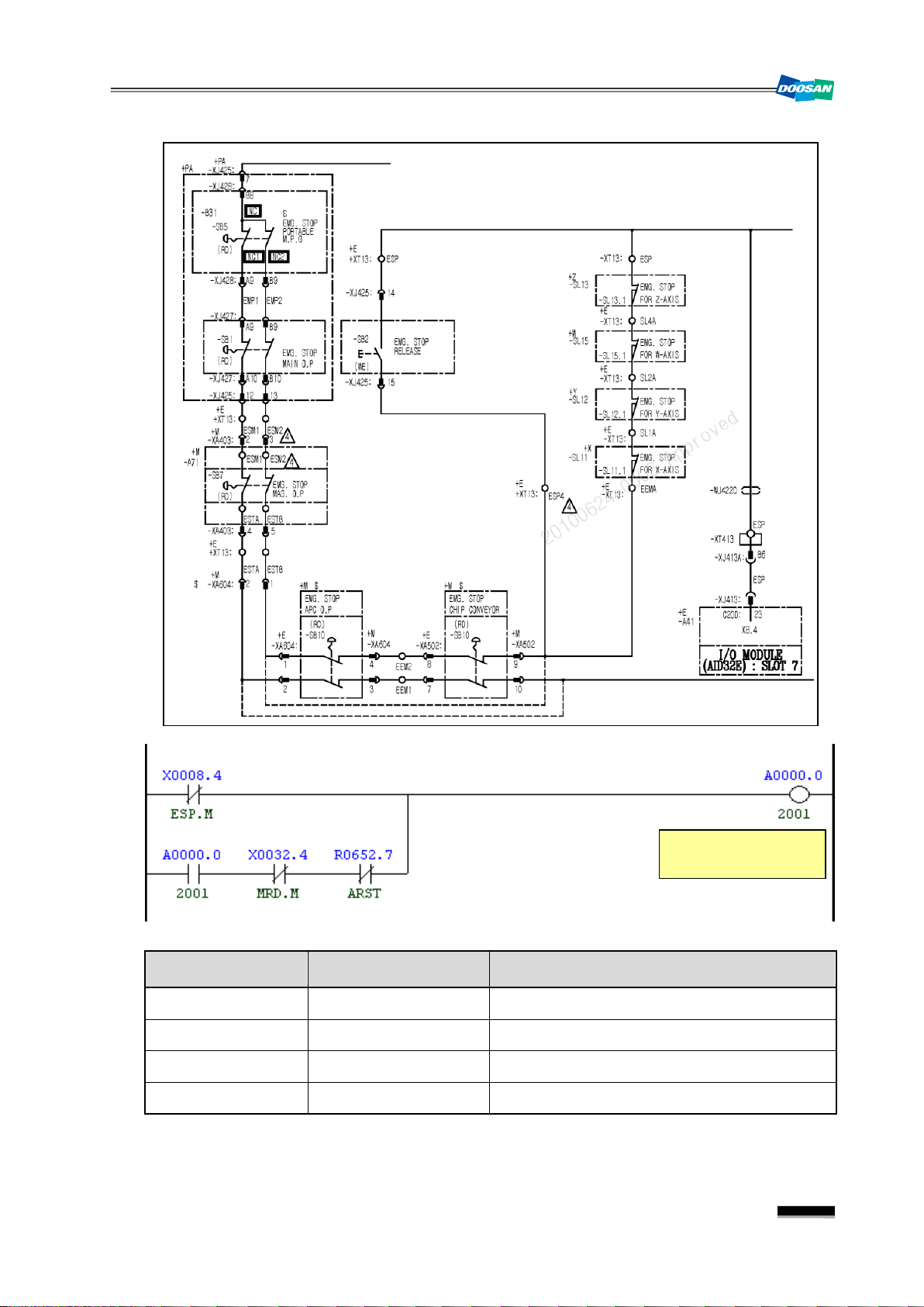
1. Emergency Alarm
1.1
2001
1) Description
The Emergency Stop push-button switch on the operation panel is pressed down, or at least
one Emergency Stop limit switch for the axes is tripped.
2) Cause of problem
① The Emergency Stop push-
② The Limit switch for an emergency stop located for each axis (X, Y, Z, W) is pressed
③ An error in the Emergency Stop switch on the OP, or the Emergency Stop limit switch for
④ Disconnection of the wiring
Emg. Button or Axes Eme rgency
the chip conveyor is pressed down.
down.
each axis, or other related parts
DBC130ALE2A
3) Action
① Check if the red mushroom push-button switch on the main OP, the tool magazine OP, or
the chip conveyor is pressed down, and if so, turn the switch counter clockwise to release
it.
② If the Limit switch for any axis (X, Y, Z, or W) is tripped, press both the Machine Ready
switch and the Emergency Release switch simultaneously to enter the Machine Ready
state. (If you want to return to the emergency stop state, simply release the switch.)
Then, move the problem-making axis in jog or handle mode so as to remove it from the
emergency stop limit switch.
③ Check the Emergency Stop push-button switch on the main OP, the Emergency Stop limit
part if necessary.
④ Disconnection of the wiring
Refer to the circuit diagram and use the electric tester to check each terminal block. If you
Part Name Part No. Symbol Spec. Maker
Switch, Emergency P/B ESWPB0439 SB1,7,9,61
Switch, Limit ESWLM0111 SL11.1,12.1,13.1,15.1
Signal Address
Emergency Stop
4
X8.4
Device
-SB1,7,9,10 I/O Module Slot 7 XJ413 (23) ESP
I/O
B30-81L2B KACON
D4C-4332 OMRON
Connector
Numbering
Page 7
DBC 130(F30i Series) DBC130ALE2A
X8.4
ESP.M
X32.4
MRD.M
Emergency Button or
Axes Emergency
Adress Symbol Coil Comment
Emergency Stop
A0.0 2001 Emg. Button or Axes Emergency
Machine Ready
R652.7 ARST Alarm Reset
5
Page 8
DBC 130(F30i Series)
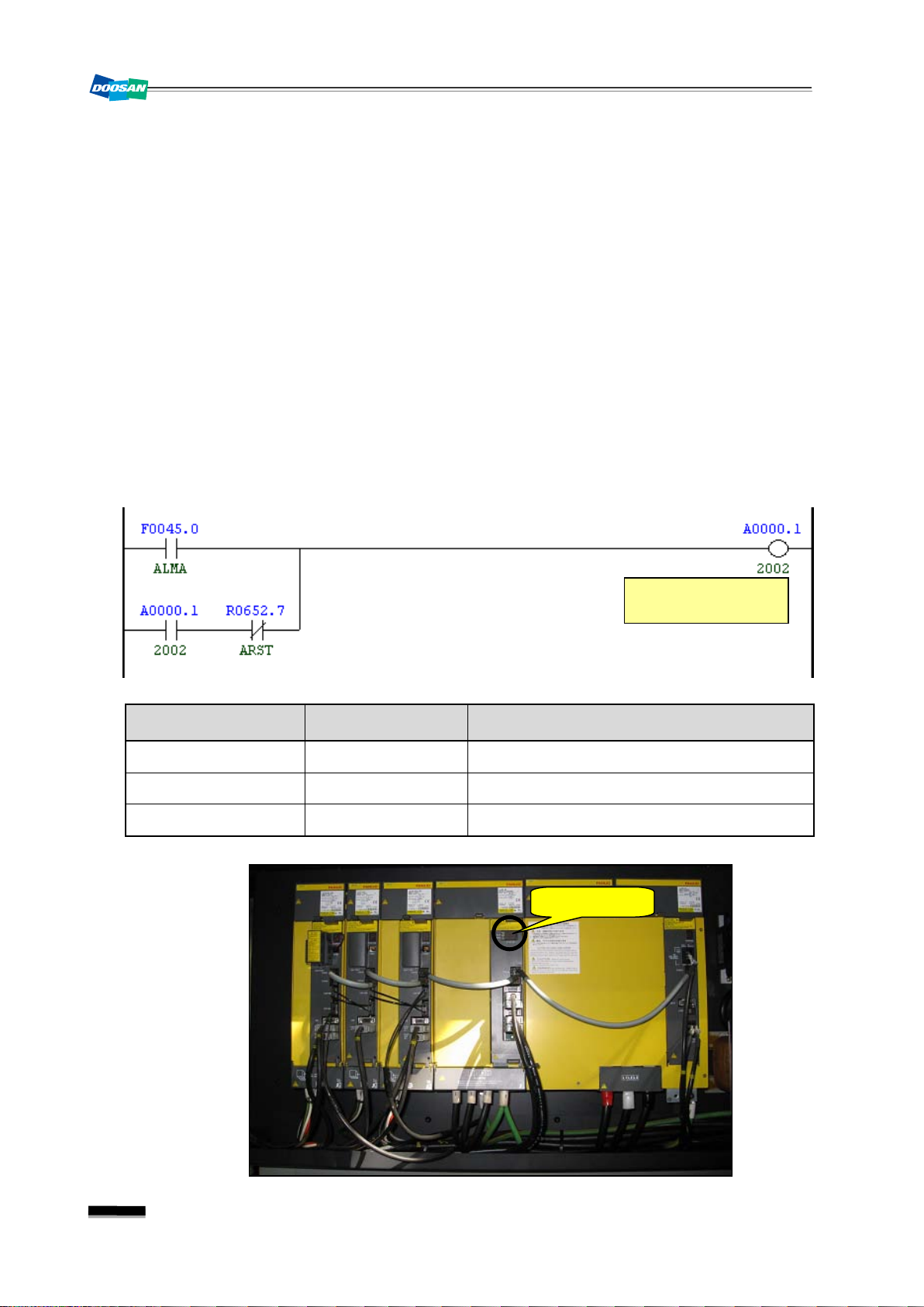
Main Spindle Servo
Alarm
Alarm Display
1.2
2002
Spindle Alarm is Detected
1) Description
There occurred an alarm from the main spindle drive unit.
2) Cause of problem
① An error found in the main spindle drive unit
② An error found in the spindle motor, power cable or signal cables
3) Action
① Check the alarm number that is displayed on the main spindle drive unit of the electric
cabinet. Take a necessary measure according to the alarm number.
☞ Refer to "Troubleshooting by the spindle amplifier alarm" in the appendix.
② Check the spindle motor for the 3-phase power source and the feedback cable if there is a
problem.
DBC130ALE2A
Address Symbol Coil Comment
F45.0 ALMA Spindle Alarm
R820.1 2002 Spindle Alarm is Detected
R652.7 ARST Alarm Reset
6
Page 9
DBC 130(F30i Series) DBC130ALE2A
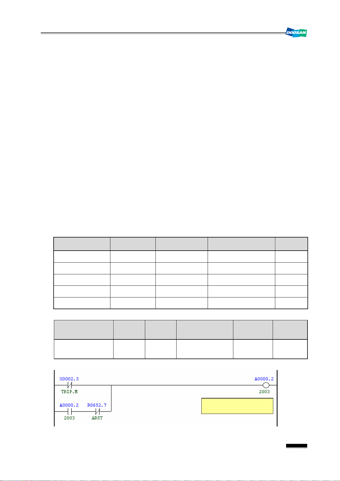
Symbol
(Pin)
TRIP.M
06
Power Circuit Overcurrent
Detected
1.3
2003
Power Circuit Overcurrent Detected
1) Description
The circuit protector that is installed in the electric cabinet is tripped.
2) Cause of problem
① The circuit protector is triggered. (Abnormal signal is detected)
② An error in power control
③ The circuit protector has an error itself.
3) Action
① Find out the cause that the circuit protector is tripped.
☞ (ex) If QF22 is tripped, check the secondary circuit (L+) of QF22 if it's short-circuited,
and take a necessary measure before turning the circuit protector back on.
② If the alarm occurs but no circuit protector is tripped, measure the resistance of each
contact point, and find out the defective circuit protector, and replace it with a new one.
☞ If you measure the resistance on the contact point of the circuit protector that is turned
on, you will get "0" ohm if it's normal.
③ If you have found nothing wrong in steps ① and ② above, that is thought to be caused by
the I/O circuit board. Check the I/O board and repair or replace it if necessary.
Part Name Part No. Symbol
Spec. Maker
Breaker, Auxiliary ENFBX0290K QF22,23,25,28,91 C60,26924,of Contact Schneider
Protector, Circuit ENFBX0268K QF22, 28 C60. 24430. 6A. 1P Schneider
Protector, Circuit ENFBX0272K QF23 C60. 24433. 13A. 1P Schneider
Protector, Circuit ENFBX0551K QF28 C60. 24436. 25A. 1P Schneider
Protector, Circuit ENFBX0266K QF91 C60. 24427. 3A. 1P Schneider
Signal Address
Circuit Protector Trip
X2.3
Device
-XT412
I/O
Input Module : Slot
Connector
Numbering
XJ412 (15) M214
7
Page 10
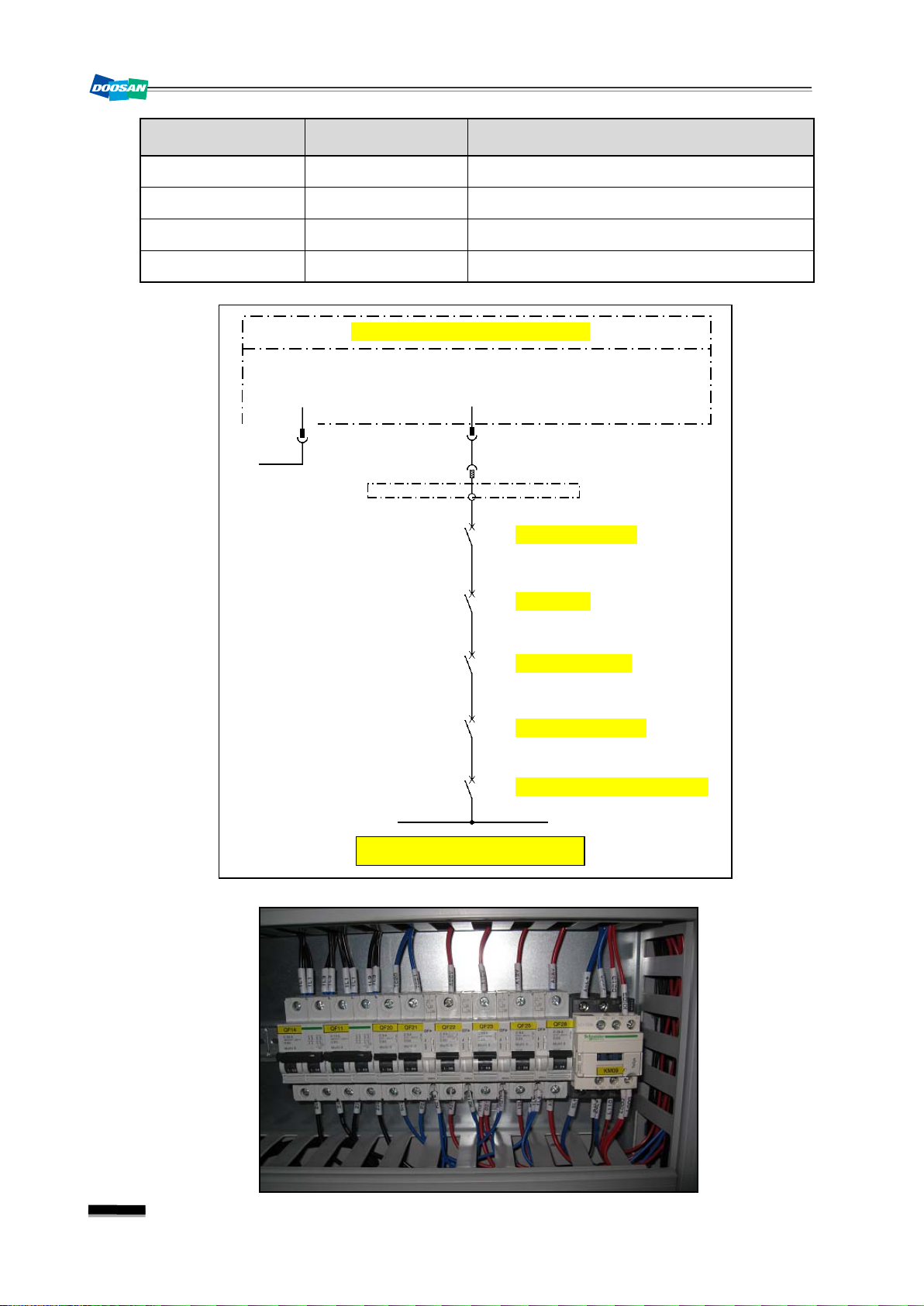
DBC 130(F30i Series)
a1
a2
M214D
-QF91
APC Motor Brake
X2.3
15
Input Module (AID32E) : Slot 6
XT412
M214
A5
Circuit Protector Trip
1L+
M
XJ412
21,36
40,41
C20C
23
24
M214C
-QF25
Work Light
a1
24
M214B
-QF23
AC 110V Source
a1
a2
M214A
-QF22
Servo Motor Brake
a1
a2
-QF28
Solenoid DC Power Source
Address Symbol Coil Comment
X2.3 TRIP.M Circuit Protector Trip Detection
R652.7 ARST Alarm Reset
A0.2 2003 Circuit Protector Trip
X2.3 TRIP.M Circuit Protector Trip Check
DBC130ALE2A
8
Page 11
DBC 130(F30i Series) DBC130ALE2A
Circuit
Circuit
Symbol
(Pin)
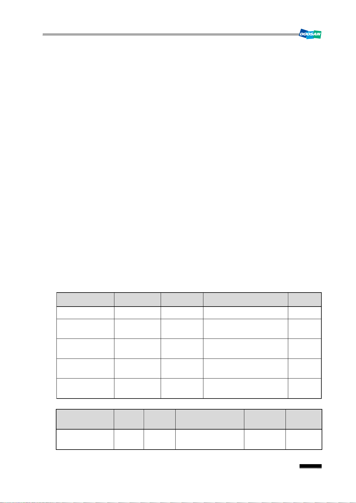
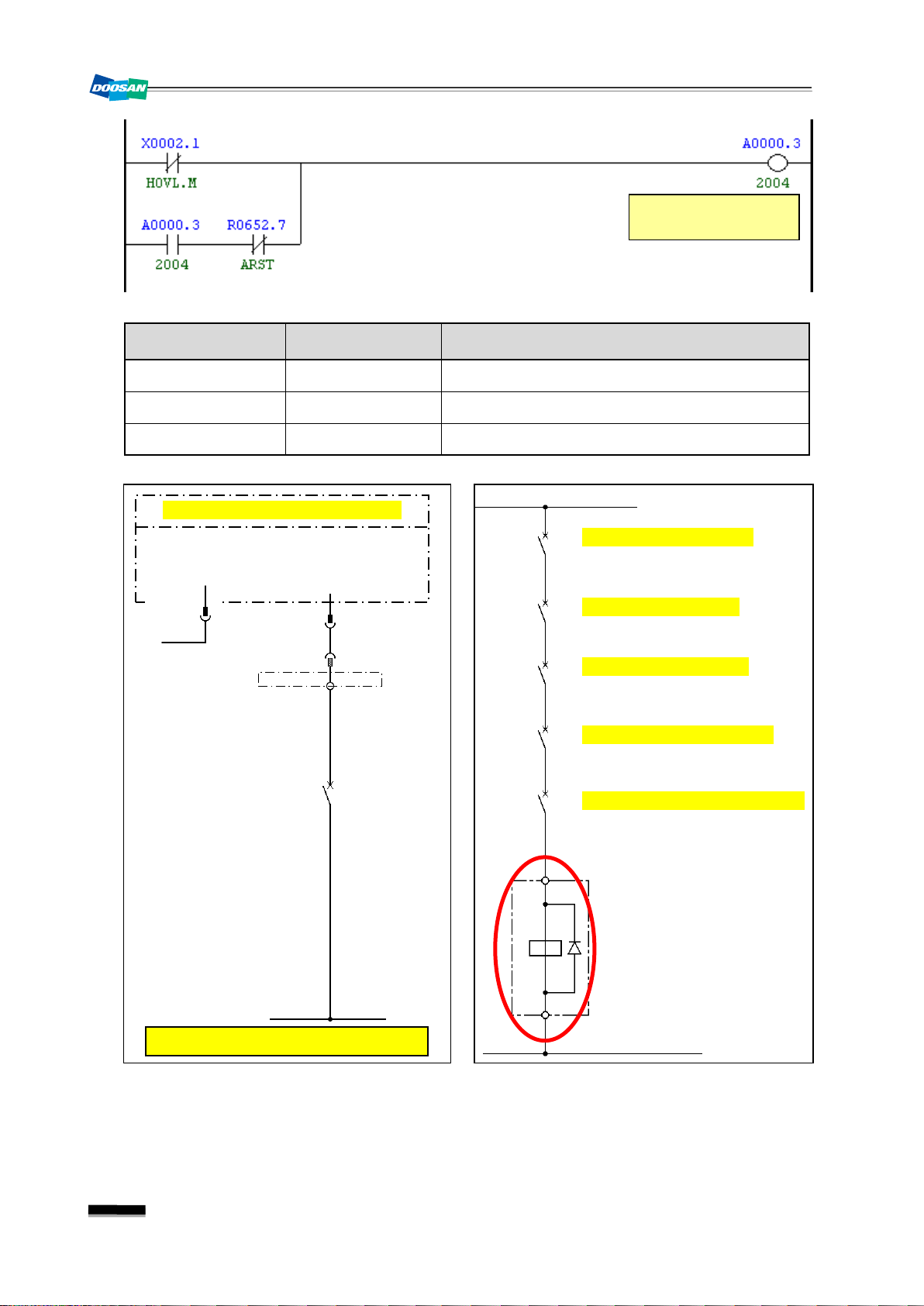
1.4
2004
Hyd. Pump Motor Overload
1) Description
Hyd. An excessive electric current is detected in the hydraulic pump motor or the lubricant
pump motor of the spindle head.
2) Cause of problem
① The hydraulic pump motor, the lubricant pump motor of the spindle head, or the power
cable is burnt out.
② The circuit breaker that detects the excessive current is overloaded or defective itself.
3) Action
① Check the hydraulic pump motor, the lubricant pump motor of the spindle head, or the
power cable if there is a problem. Repair or replace the defective part if necessary.
② Check the circuit breaker for the load settings and make correction if necessary. If the
circuit breaker itself has an error, replace it with a new one.
(You can detect a defective circuit breaker by checking the resistance on either circuit of
M212 or 1L+)
▪ Overload settings
QM31 : 5.5 Kw : 24 A
QM33 : 3.7 Kw : 16.1 A
QM34 : 0.1 Kw : 0.7 A
QM73 : 1.5 Kw : 7 A
QM10 : 1.5 A
Part Name Part No. Symbol Spec. Maker
Breaker, Auxiliary ENFBX0290M QM33,34,73 TESYS. GVAE20. 2A Schneider
Breaker, Motor
Breaker, Motor
Circuit
Breaker, Motor
Circuit
Breaker, Motor
ENFBX0269M QM31 TESYS. GV3P32. 23-32A Schneider
ENFBX0261M QM33 TESYS. GV2ME21. 17-23A Schneider
ENFBX0254M QM34 TESYS. GV2ME05. 0.63-1A Schneider
ENFBX0259M QM73 TESYS. GV2ME14. 6-10A Schneider
Signal Address
Hydraulic Motor
Overload
X2.1
HOVL.M
Device
I/O
-KA11 Input Module Slot 06 XJ412 (32) M212
Connector
Numbering
9
Page 12
DBC 130(F30i Series)
Hyd. Pump Motor
Overload
9
5
-KA11
X2.1
32
Input Module (AID32E) : Slot 6
XT412
M212
A3
M
XJ412:
21,36
40,41
C20C:
Hydraulic Motor Overload
1L+
1L+
-QM73
a1
a2
KA11C
-QM34
a1
A2
KA11B
-QM33
a1
a2
KA11A
-QM31
a1
a2
KA11
14
13
Hydraulic 1 Pump Motor
Hydraulic Pump Motor
Table Lub. Pump Motor
Recovery Pump Motor/Spd
M
-QM10
a1
a2
Spindle Fan Motor & Motor Fan
KA11
DBC130ALE2A
Address Symbol Coil Comment
X2.1 HOVL.M Hydraulic Pump Motor Overload
A0.3 2004 Hydraulic Pump Motor Overload
R652.7 ARST Alarm Reset
10
Page 13
DBC 130(F30i Series) DBC130ALE2A
11
Page 14
DBC 130(F30i Series)
Symbol
(Pin)
Main Hyd. Pump
Pressure Switch
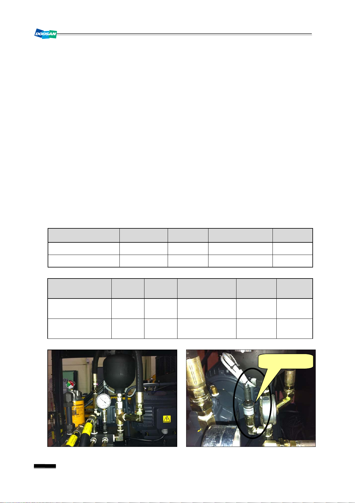
1.5
2005
Hyd. Pressure Down Alarm
1) Description
The pressure of the hydraulic power unit falls below the setting value of the hydraulic
pressure switch, causing the hydraulic pressure switch to be tripped.
2) Cause of problem
① The hydraulic power unit has an error or its pressure falls below 20kg/㎠.
② The hydraulic pressure switch or any of its parts is defective.
3) Action
① Turn the pressure value of the hydraulic power unit clockwise to adjust the pressure to
50kg/㎠.
② The pressure switch of the hydraulic power unit has an error, or the wiring or related
component parts are defective.
Check the hydraulic power unit, the pressure switch, and the wiring from the switch to the
electric cabinet as well as the I/O board, and make repair or replacement if you find a
problem.
DBC130ALE2A
Part Name Part No. Symbol Spec. Maker
Cable, Pressure Switch ECBLS0167F -WK11 BKS B19-1-05 BALUFF
Switch Pressure R37983 -SP01
Signal Address
Hyd. Pressure Check
Hydraulic Motor Run
X8.3
HDPS.M
Y2.0
HYDM.R
Device
-SP31 Input Module Slot 7 XJ413(6) SP31
-KA31A
Output Module Slot
EDS810-060-0-024
I/O
Connector
2
(02) KA31A
HYDACS
Numbering
12
Page 15
DBC 130(F30i Series) DBC130ALE2A
Hydraulic Pressure
Down
Aux. Hyd. Pressure
O.K Flag
Hyd. Pressure O.K
Hyd. Pressure Check
Delay Time
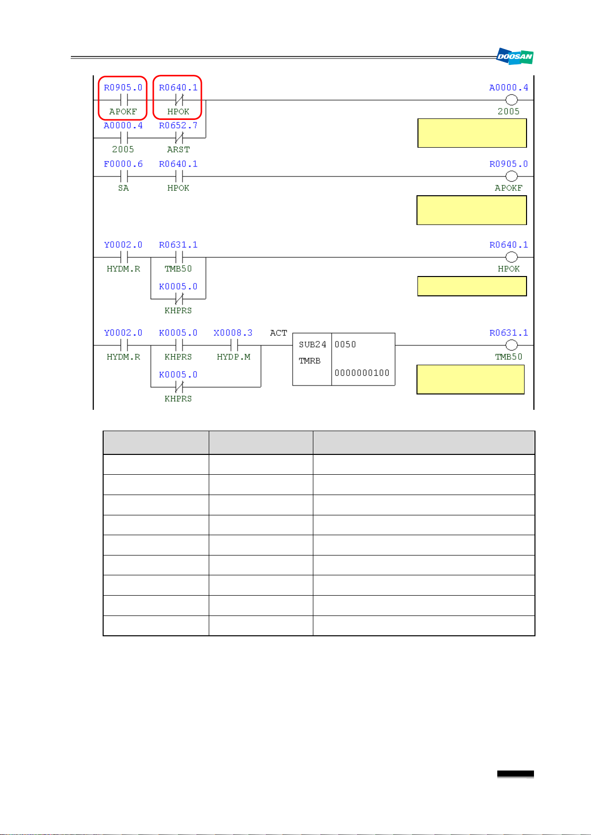
Address Symbol Coil Comment
R905.0 APOKF Aux. Hyd. Pressure OK Flag
R640.1 HPOK Hyd. Pressure OK
A0.4 2005 Hyd. Pressure Down Alarm
R652.7 ARST Alarm Reset
F0.6 SA Servo Ready
Y2.0 HYDM.R Hyd. Pump Motor Run
R631.1 TMB50 Hyd. Pressure Check Delay Time
K5.0 KHPRS Hyd. Pressure SW Used
X8.3 HYDP.M Hyd. Pressure Check
13
Page 16
DBC 130(F30i Series)
Symbol
(Pin)
Data of the data table---0002/0011(gear shift rpm)
Gear shift rpm in gear1 range
Gear shift rpm in gear2 range
Gear shift rpm in gear3 range
D0461 #
D0460 #
DATA
25
25
0000
D0462 #
ADDRESS
MEANING
25
0001
0002
NO.
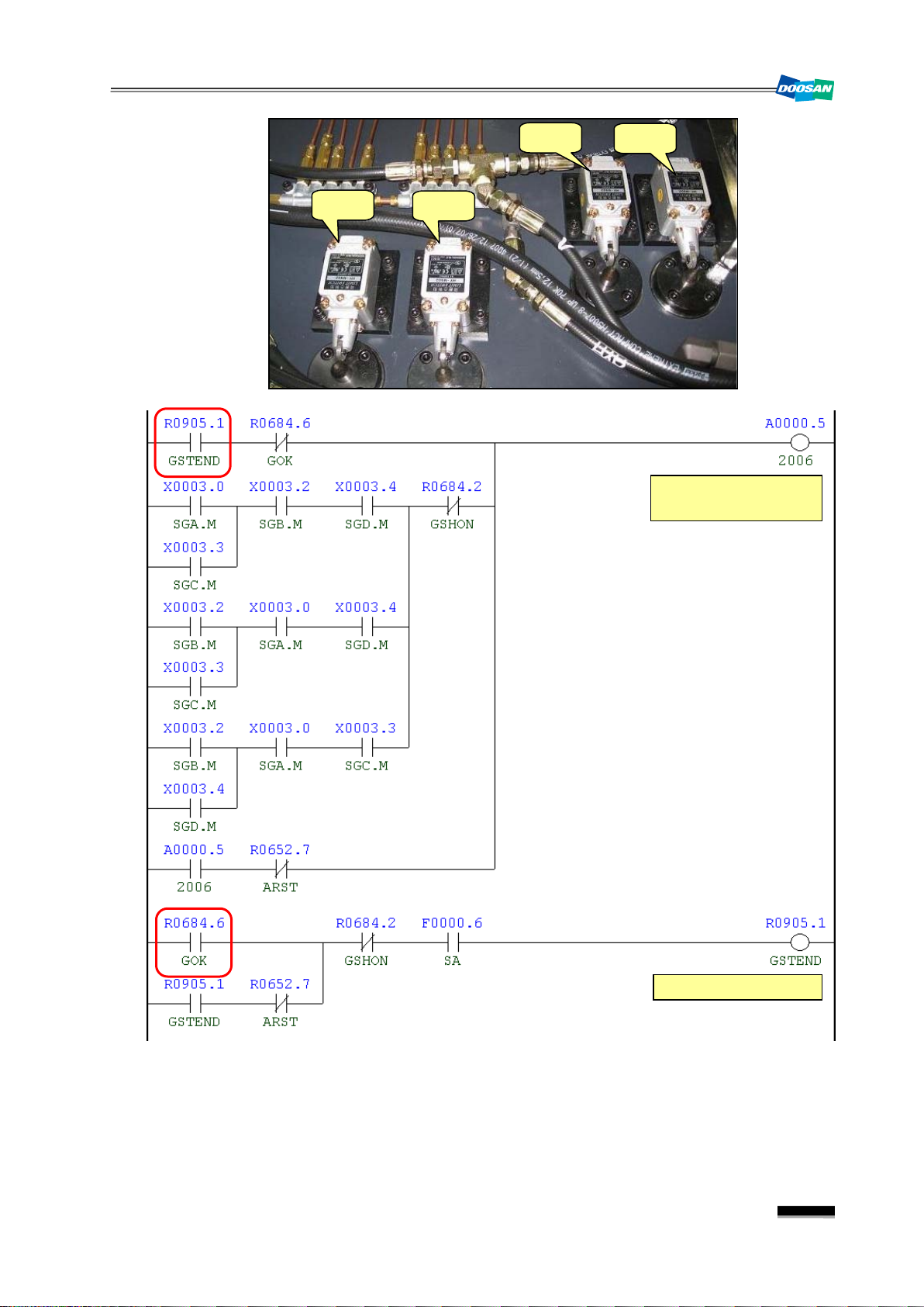
1.6
2006
Spindle Gear Shift Check Switch Alarm
1) Description
3 or more of 4 check switches (Low, Middle, High, etc) on the spindle head gear range were
tripped, or none of them was tripped.
2) Cause of problem
The check switch for the main spindle gear range has short-circuited or any of its component
parts is defectiv e.
3) Action
Check the gear box switch of the main spindle if it works properly on the DGN screen, and
take a necessary measure.
Note 1) Spindle Gear Shifting I/O Settings
DBC130ALE2A
Signal Address
Device
I/O
Connector
Gear 1 Check X3.0 (SGA.M) -SL11 Input Module Slot 06 XJ412 (12) SL11
Gear 2 Check X3.2 (SGB.M) -SL13 Input Module Slot 06 XJ412 (44) SL13
Gear 3 Check X3.3 (S G C.M) -SL14 Input Module Slot 06 XJ412 (11) SL14
Gear 4 Check X3.4 (S G D.M) -SL15 Input Module Slot 06 XJ412 (27) SL15
Spindle Gear 1 Y4.0 (GR1.V) -KAR40 Output Module Slot 3 XJ400 (16) YV14
Spindle Gear 2 Y4.1 (GR2.V) -KAR41 Output Module Slot 3 XJ400 (32) YV15
Spindle Gear 3 Y4.2 (GR3.V) -KAR42 Output Module Slot 3 XJ400 (48) YV18
Spindle Gear 4 Y4.3 (GR4.V) -KAR43 Output Module Slot 3 XJ400 (15) YV19
Note 2) Spindle Gear Range Shifting RPM (D460~D462)
Numbering
14
Page 17
DBC 130(F30i Series) DBC130ALE2A
Activate the
vertical soft key
1
2
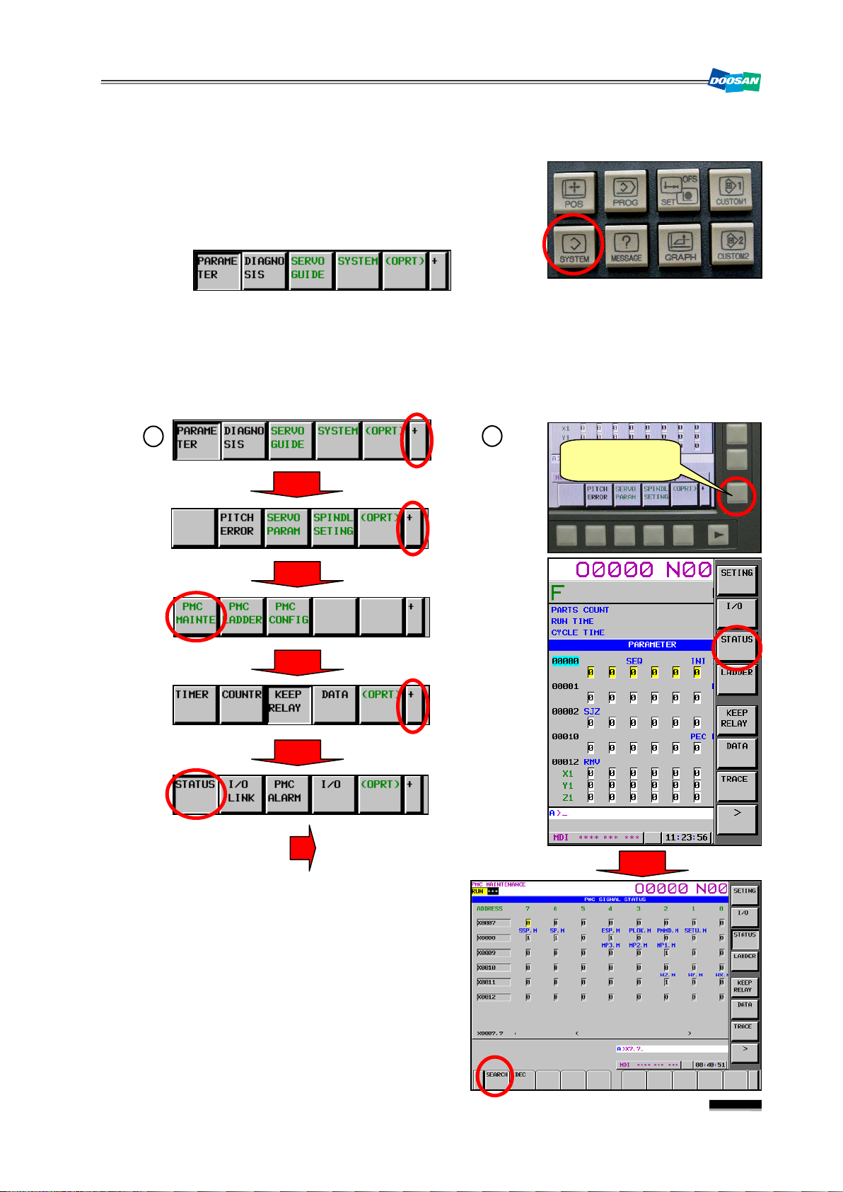
Note 3) How to move to DGN (Diagnostic)
(1) Press the “SYSTEM” button in the right side of the main
OP monitor.
The following soft key bar will be displayed at the
bottom.
(2) Move to the DGN screen.
① Press the soft keys one after another to move to the DGN screen.
② Press any soft key in the right corner to activate the vertical soft key bar, and press the
[STATUS] key.
(3) Enter a desired DGN address and press
[SEARCH] to display the DGN screen of
your choice.
15
Page 18
DBC 130(F30i Series)
SL11
SL13
SL14
SL15
YV19
YV18
YV15
YV14
Middle
1 2 3
4
SL11
SL13
SL14
SL15
SL12
YV15
YV14
YV19
YV18
YV11
Gear Shift
Tool Unclamp
P
T
DBC130ALE2A
Note 4) How to read DGN (Diagnostic)
Ex) X 0007 0 0 1 1 0 0 1 0
Bit 1, 4 and 5 in Address X7 turn ON while Bit 0, 2, 3, 6 and 7 turn OFF.
Symbol 0 0 1 1 0 0 1 0
Bit No Bit 7 Bit 6 Bit 5 Bit 4 Bit 3 Bit 2 Bit 1 Bit 0
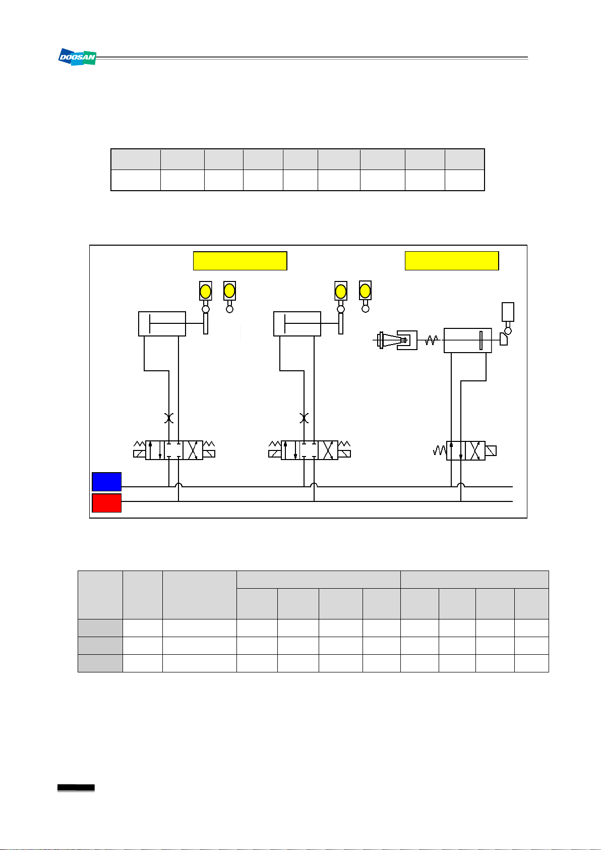
Note 5) Hydraulic circuit diagram of the spindle head
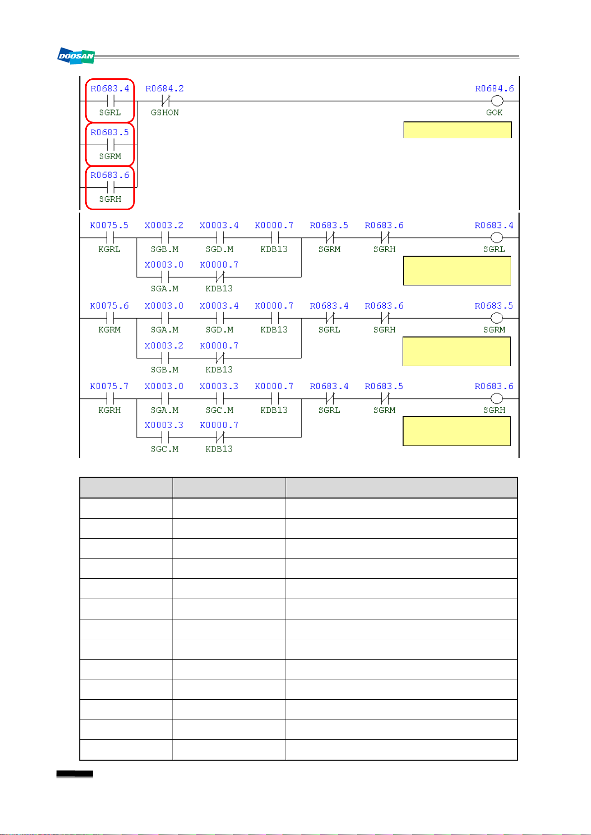
Note 6) Spindle Gear Selection Table
Gear
State
High
Keep
Relay
S-Code
K75.5 S0~S246 1 0 1 0 0 1 0 1
K75.6 S247~S806 1 0 0 1 1 0 0 1
Low
K75.7 S807~S2500 0 1 0 1 1 0 1 0
X3.0
Input Signal Output Signal
X3.2
X3.3
X3.4
Y4.3
Y4.2
Y4.1
Y4.0
16
Page 19
DBC 130(F30i Series) DBC130ALE2A
SL11
SL13
SL14
SL15
Spindle Gear Shift
Check Switch Alarm
Gear Shift End Flag
17
Page 20
DBC 130(F30i Series)
Gear Shift O.K
Gear Shift Range
Low
Gear Shift Range
Middle
Gear Shift Range
High
DBC130ALE2A
Address Symbol Coil Comment
R905.1 GSTEND Gear Shift End Flag
R684.6 GOK Gear Shift O.K
X3.0 SGA.M Spindle Gear A/S-Unclamp Built
X3.2 SGB.M Spindle Gear Shift Status B
X3.3 SGC.M Spindle Gear Shift Status C
X3.4 SGD.M Spindle Gear Shift Status D
R684.2 GSHON Gear Shift On
A0.5 2006 Gear Shift Check Switch Alarm
R652.7 ARST Alarm Reset
R905.1 GSTEND Gear Shift End Flag
R683.4 SGRL Spindle Gear Shift Low
R683.5 SGRM Spindle Gear Range Middle
R683.6 SGRH Spindle Gear Range High
18
Page 21

DBC 130(F30i Series) DBC130ALE2A
Symbol
(Pin)
On State
PMON.M
Interlock
SDIC.M
KM10 (Magnet)
Auxiliary “a” contact
KM10
(Magnet)
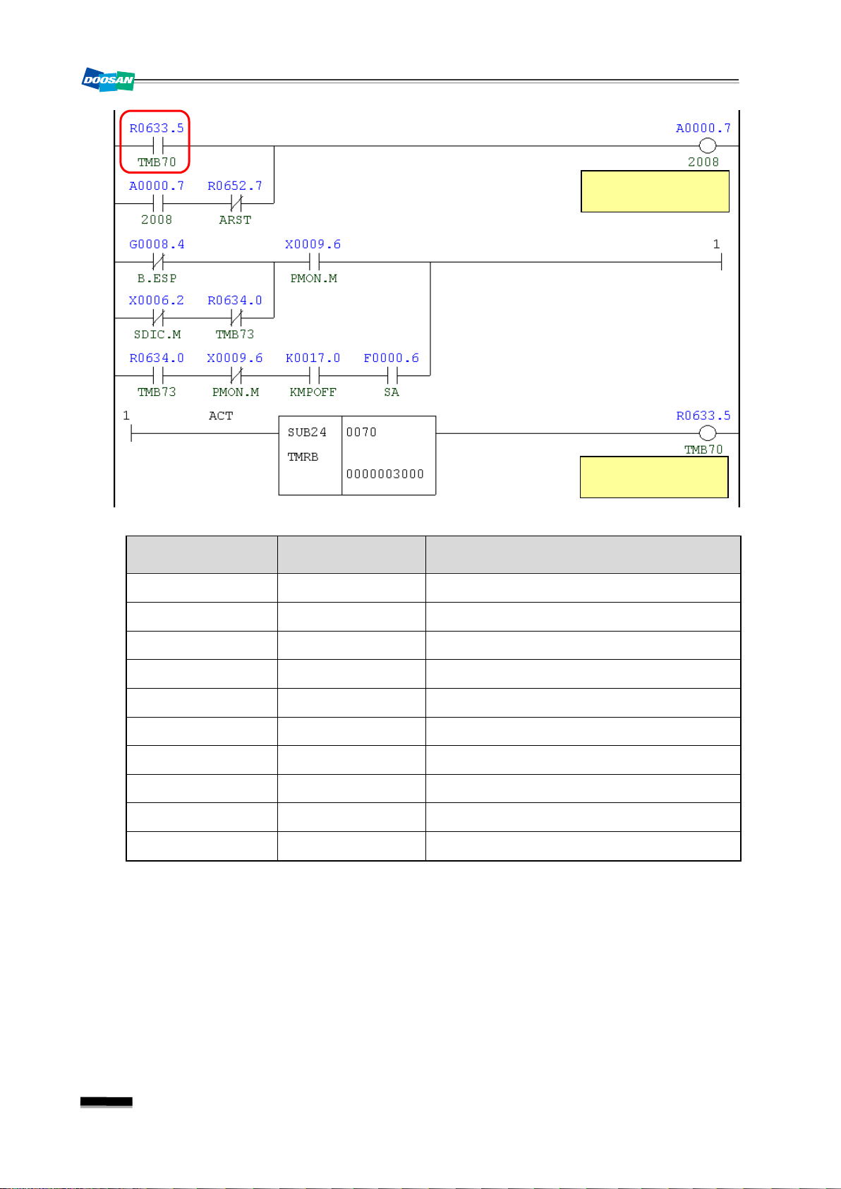
1.7
2008
PSM Contact Check Error
1) Description
There occurred an error while KM10 magnetic contactor was operating.
2) Cause of problem
The operation of KM10 did not comply with the intended signal.
3) Action
① The check signal (X9.6) of the magnetic contactor should turn on only while KM10 is
operating.
② Set "Keep Relay K17.0" to 1 if you want to enable the option of Motor Power On/Off.
☞ If you set "K17.0=(1)" to enable the option of Motor Power ON/OFF, KM10 magnetic
contactor turns off if the door is open, and turns on if the door is close.
Signal Address
Power Supply Contact
Splash Guard Door
X9.6
X6.2
Device
I/O
Connector
Numbering
-KM10 Input Module Slot 07 XJ413 (01) PMON
-S61 Input Module Slot 07 XJ413(48) SS61B
19
Page 22
DBC 130(F30i Series)
PSM Contact Check
Error
Power Module Alarm
Check Time
DBC130ALE2A
Address Symbol Coil Comment
R633.5 TMB70 Power Module Alarm Check Time
A0.7 2008 PSM Contact Check Error
R652.7 ARST Alarm Reset
G8.4 B.ESP Emergency Stop
X6.2 SDIC.M Splash Guard Door Interlock
R634.0 TMB73 Connect Delay Time Again
X9.6 PMON.M Power Supply Magnet On State
K17.0 KMPOFF Module Elec. Off D-Open
F0.6 SA Servo Ready
X17.7 MENB.M Machine Enable Switch On
20
Page 23
DBC 130(F30i Series) DBC130ALE2A
to operate the machine regardless of whether the axes return to their reference
Return to Ref. Point
Manually
Ref. Point Return
Interlock. Alarm
2. Cycle Alarm
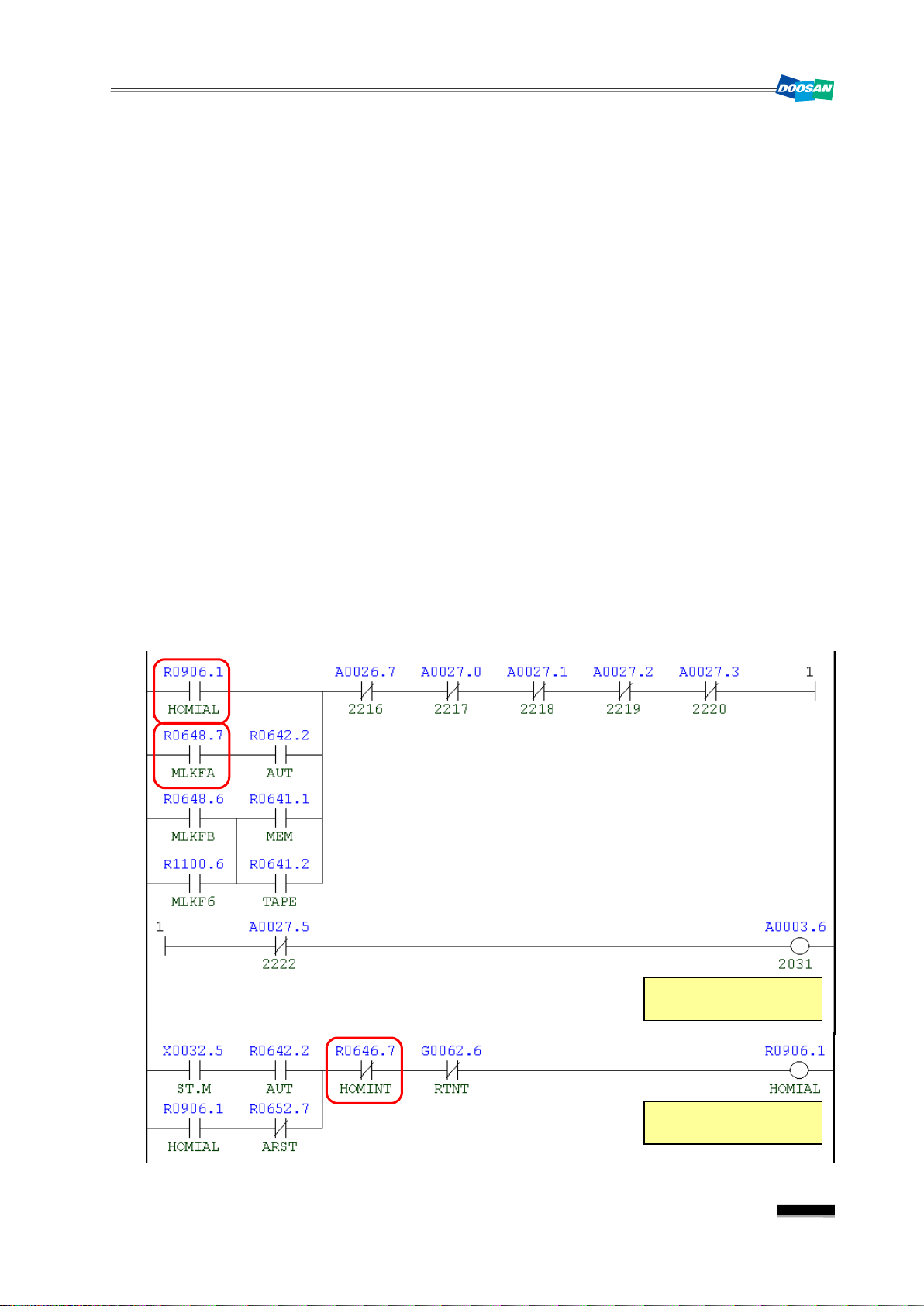
2.1
2031
1) Description
A message prompting you to manually return the axis to the reference point
2) Cause of problem
① The machine was instructed to operate before all axes had returned to their respective
② In the Machine Lock state, AUTO mode (EDIT, MEMORY, TAPE, MDI) was selected. (X,
③ In the Machine Lock state, EDIT or MEMORY mode was selected. (B, 6 axes)
3) Action
① Return to the reference point manu al l y
② If you want
③ In the Machine Lock st at e, the ma chi n e c a n b e in st r u ct e d to ope r at e i n AU TO mo d e o nl y
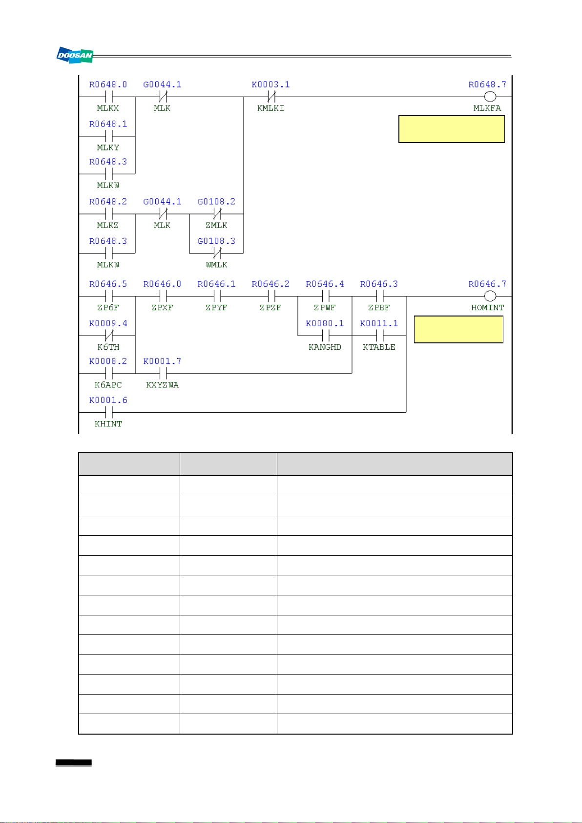
Return to Ref. Point in Manual
reference point.
Y, Z, W)
point, set "Keep Relay K1.6" to 1.
after the axes have returned to their respective reference point.
21
Page 24
Home Position
Interlock
Machine Lock on
Flag X, Y, Z, W
DBC 130(F30i Series)
DBC130ALE2A
Address Symbol Coil Comment
R906.1 HOMIAL Ref. Point Return Interlock Alarm
R648.7 MLKFA Machine Lock On Flag X, Y, Z, W
R642.2 AUT Auto Mode
R648.6 MLKFB Machine Lock On Flag B-Axis
R1100.6 MLKF6 Machine Lock On Flag 6-Axis
R641.1 MEM Memory Mode
R641.2 TAPE Tape Mode
A26.7 2216 Must Be Return to Ref. Point X
A27.0 2217 Must Be Return to Ref. Point Y
A27.1 2218 Must Be Return to Ref. Point Z
A27.2 2219 Must Be Return to Ref. Point W
A27.3 2220 Must Be Return to Ref. Point B
A27.5 2222 6th Axis Clamp/Unclamp Alarm
22
Page 25
DBC 130(F30i Series) DBC130ALE2A
Address Symbol Coil Comment
A3.6 2031 Return to Ref. Point in Manual
X32.5 ST.M Cycle Start
R652.7 ARST Alarm Reset
R646.7 HOMINT Home Position Interlock
G62.6 RTNT Rigid Tapping Retraction Start
R648.0 MLKX Machine Lock X-Axis
R648.1 MLKY Machine Lock Y-Axis
R648.3 MLKW Machine Lock W-Axis
G44.1 MLK Machine Lock
R648.2 MLKZ Machine Lock Z-Axis
G108.2 ZMLK Z-Axis Machine Lock
G108.3 WMLK W-Axis Machine Lock
K3.1 KMLKI Machine Lock Ref. Point Invalid
23
Page 26
DBC 130(F30i Series)
Symbol
(Pin)
Feed Hold Push
Button is Pressed
2.2
2032
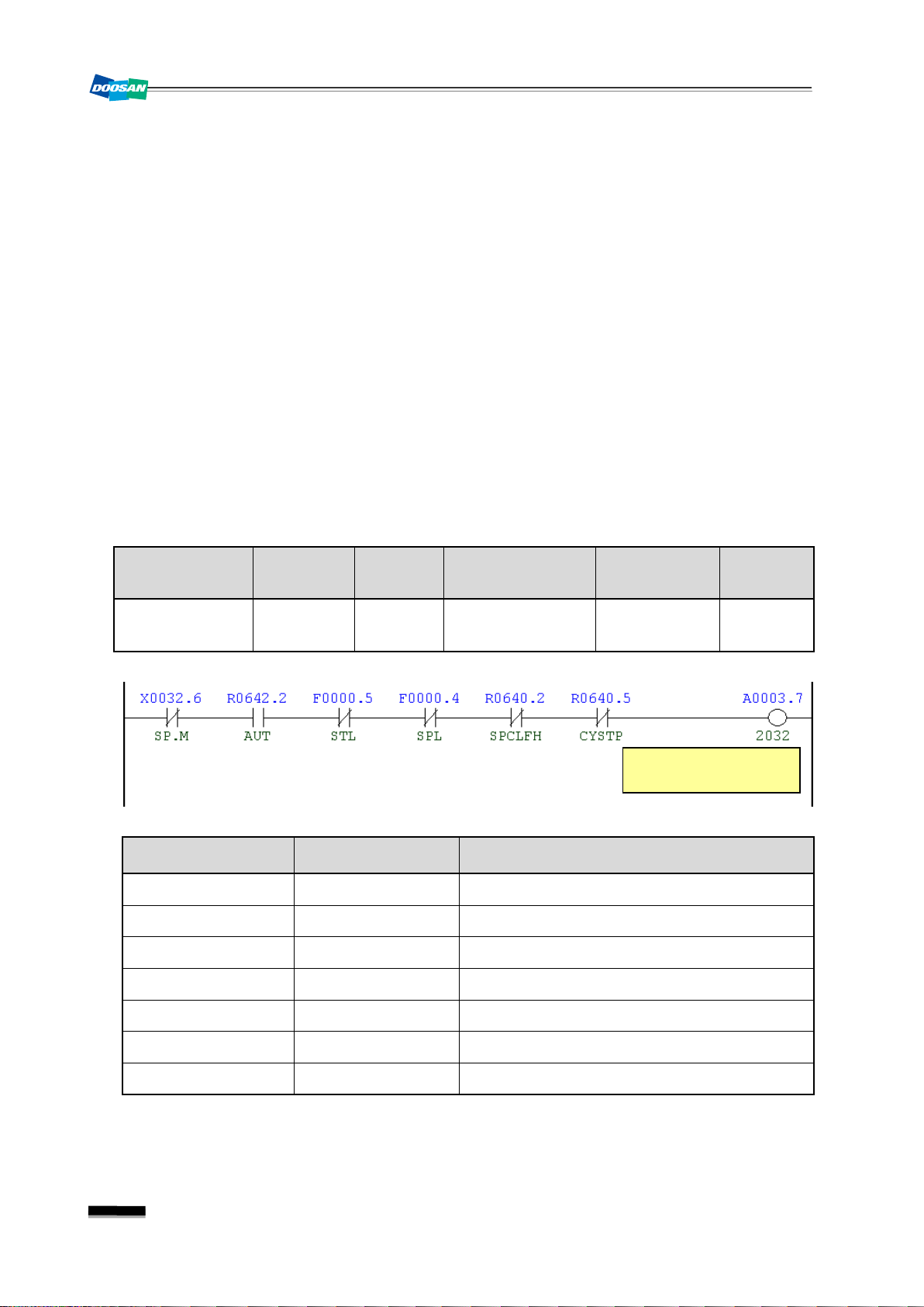
Feed Hold Push Button is Pressed
1) Description
An error in the signal of the feed hold switch while the program is running (in AUTO mode)
2) Cause of problem
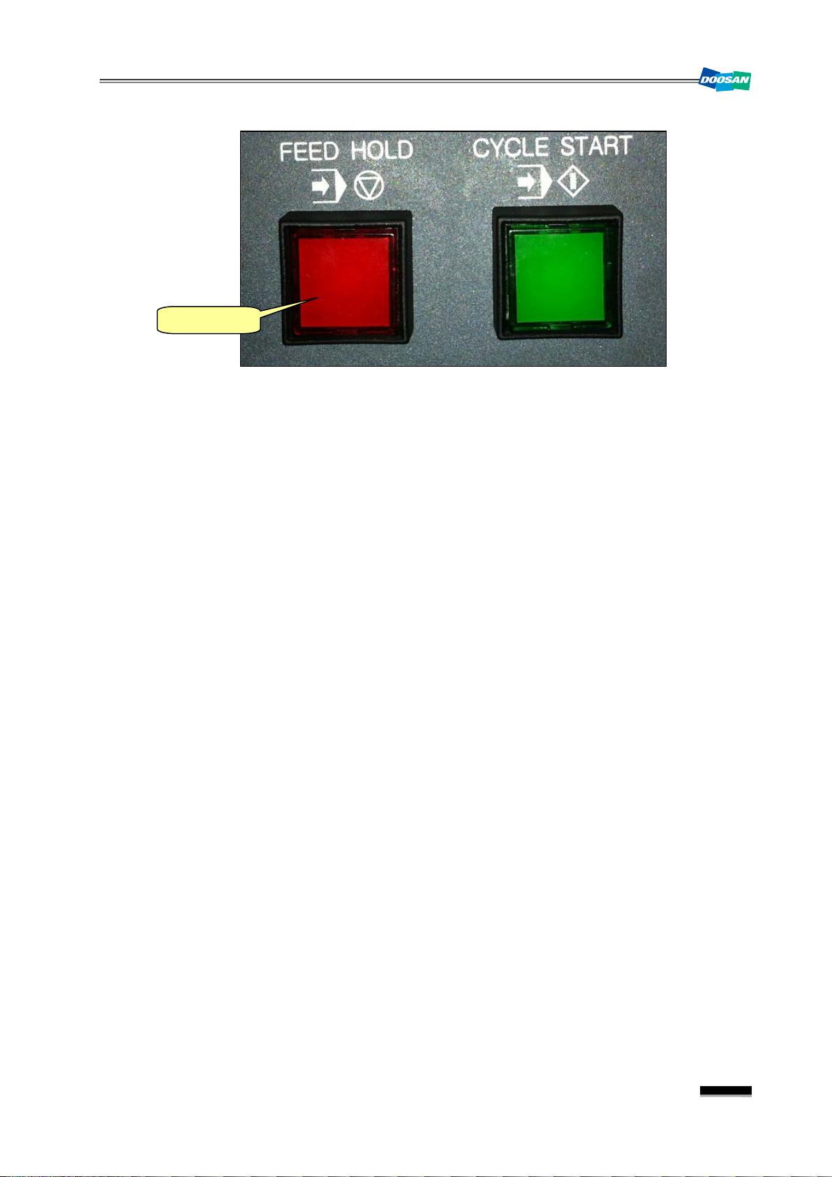
① The feed hold switch on the main OP is tripped.
☞ The feed hold switch enables you to stop running the program instantly without
instructing the emergency stop.
② A short-circuit or defective part in the feed hold switch
3) Action
① If you have pressed the feed hold switch by necessity, release the switch to set off the
alarm. Then, you can press the Cycle Start switch to resume running the program.
② Turn the feed hold switch manually to check the input signal on the DGN screen of PMC.
Take necessary measures (reconnect the wiring, etc) to restore normal conditions.
DBC130ALE2A
Signal Address
X32.6
Feed Hold
SP.M
Device
-SB17
I/O
Distribute I/O
Module(A)
Connector
Numbering
XCE56A(A05) SB17
Address Symbol Coil Comment
X32.6 SP.M Cycle S t op
R642.2 AUT Auto Mode
F0.5 STL Cycle Start
24
F0.4 SPL Feed Hold
R640.2 SPCLFH Spindle & Coolant At Feed Hold
R640.5 CYSTP Cycle Stop
A3.7 2032 Feed Hold Push Button is Pressed
Page 27
DBC 130(F30i Series) DBC130ALE2A
Feed Hold
25
Page 28
DBC 130(F30i Series)
if
Symbol
(Pin)
Air Pressure Down
Alarm
Main Air Check
D-Time
2.3
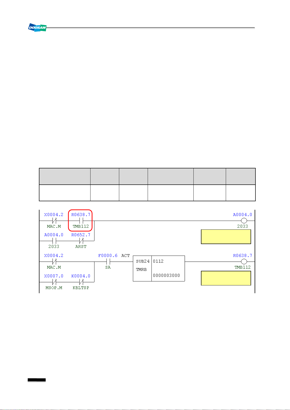
2033
Air Pressure down Alarm
1) Description
The air pressure switch is tripped because the air pressure falls below the specified value.
2) Cause of problem
①
The factory-supplied air pressure falls below the standard (4kg).
②
The air pressure switch or any of its parts is defective.
3) Action
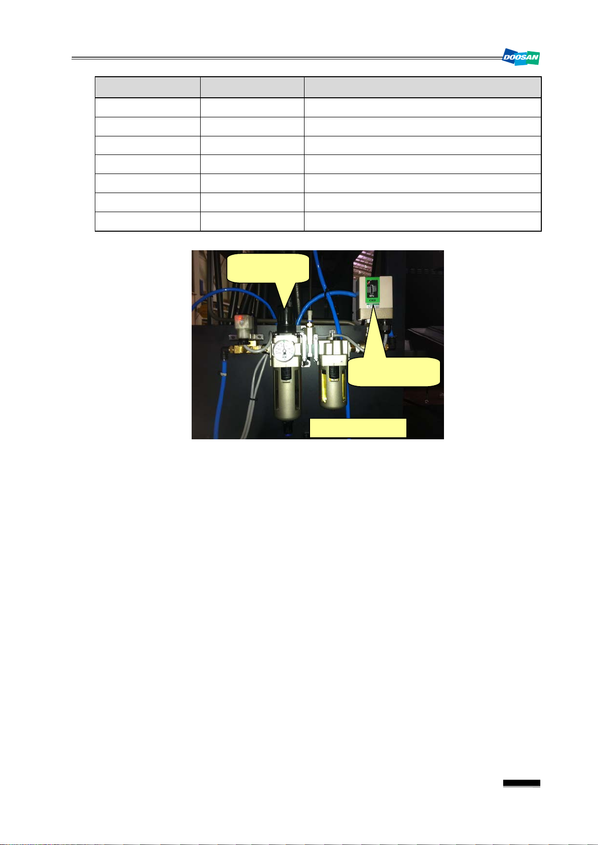
① Increase the factory-supplied air pressure to more than 5kg/㎠.
▪ Check the air pressure measurement displayed on the gauge of the air service unit, and
it's below 4kg/㎠, turn the air pressure handle to the right. If the gauge does not increase
any further, this indicates the current air pressure is not appropriate.
② Check the air pressure switch, wiring and I/O module if there is no error. And make repair
or replacement if necessary.
DBC130ALE2A
Signal Address
Main Air Pressure
Check
X4.2
MAC.M
Device
-SP8C
I/O
Input Module :
Slot 06
Connector
Numbering
XJ412 (39) SP8C
26
Page 29
DBC 130(F30i Series) DBC130ALE2A
R638.7
TMB112
Main Air Check D-Time
A4.0
2033
Air Pressure Down Alarm
R652.7
ARST
Alarm Reset
Air Supply Unit
Air Pressure
Adjustable Valve
Air Pressure
Switch (SP8C)
Address Symbol Coil Comment
X4.2 MAC.M Main Air Pressure Check
X7.0 MSOP.M Mist Oil Operating Pressure
K4.0 KBLTSP Built In Spindle Used
F0.6 SA Servo Ready
27
Page 30

DBC 130(F30i Series)
Symbol
(Pin)
Motor Overload
MOVL.M
Slot 06
Coolant Motor
Overload Alarm
2.4
2034
Coolant & Lub. Pump Overload
1) Description
An excessive electric current is detected in the coolant or lubricant pump motor.
2) Cause of problem
① The coolant or lubricant pump motor, or the power cable is burnt out.
② The circuit breaker that detects the excessive current is overloaded or defective itself.
3) Action
① Check the coolant or lubricant pump motor, or the power cable, and repair or replace a
defective one if found.
② Check the circuit breaker for the load settings and make correction if necessary. If the
circuit breaker itself has an error, replace it with a new one.
☞ Overload settings
QM41 (Flood Coolant Pump Motor) : 1.5 Kw : 7 A / 2.2 Kw : 11 A
DBC130ALE2A
QM42 (T-T-S Coolant Pump Motor) : 1.5 Kw : 7 A / 3.7 Kw : 17 A
QM43 (Cool Jet T-S-C Unit) : 5.5 Kw : 23.9 A / 3.7Kw : 17A
QM422 (Recovery Pump Motor/C-J) : 0.9 Kw : 5.2 A
Part Name Part No. Symbol Spec. Maker
Breaker, Auxiliary ENFBX0290M QM41,42,43,422 TESYS. GV2ME22. 20-25A Schneider
Breaker, Motor Circuit ENFBX0259M QM41,QM42 TESYS. GV2ME14. 6 -10A Schneider
Breaker, Motor Circuit ENFBX0285M QM41 TESYS. GV2 ME16. 9-14A Schneider
Breaker, Motor Circuit ENFBX0261M QM42, QM43 TESYS. GV2ME21. 17-23A Schneider
Breaker, Motor Circuit ENFBX0262M QM43 TESYS. GV2ME22. 20-25A Schneider
Breaker, Motor Circuit ENFBX0258M QM422 TESYS. GV2ME10. 4-6.3A Schneider
Signal Address
Coolant & Lub.
X2.2
Device
-M213
I/O
Input Module :
Connector
Numbering
XJ411 (48) M213
28
Page 31

DBC 130(F30i Series) DBC130ALE2A
A4.1
2034
Coolant Motor Overload Alarm
R652.7
ARST
Alarm Reset
9
5
-KA12
X2.2
48
Input Module (AID32E) : Slot 6
XT412
M213
A4
M
XJ412
21,36
40,41
C20C
Coolant & Lub. Motor Overload
1L+
1L+
-QM422
23
24
KA11C
-QM43
23
24
KA11B
-QM42
23
24
KA11A
-QM41
23
24
KA12
KA12
14
13
Flood Coolant Pump Motor
T-T-S Coolant Pump Motor
Cool Jet T-S-C Unit
Recovery Pump Motor/C-J
Address Symbol Coil Comment
X2.2 MOVL.M Lub. & Coolant Motor Overload
29
Page 32

DBC 130(F30i Series)
Symbol
(Pin)
TSCA.M
Slot 07
Additional Coolant
Unit Alarm
2.5
2035
Addition Coolant Unit Alarm
1) Description
An error occurred in an external coolant unit.
2) Cause of problem
① The coolant pressure of the TSC unit has decreased, or the filter of the TSC filter unit is
clogged.
② The pressure switch has an error or the wiring has a problem.
3) Action
① Take necessary measures to solve the problems of both the TSC unit and the filter.
② Check the pressure switch and the wiring, and repair or replace a defective one if
necessary.
DBC130ALE2A
Signal Address
T-S-C Unit Alarm
X7.6
Device
-SP15
I/O
Input Module :
Address Symbol Coil Comment
X7.6 TSCA.M T.S.C Un it Al a r m
F0.6 SA Servo Ready
A4.2 2035 Addition Coolant Unit Alarm
R652.7 ARST Alarm Reset
Connector
XJ413 (10)
30
Page 33

DBC 130(F30i Series) DBC130ALE2A
31
Page 34

DBC 130(F30i Series)
Symbol
(Pin)
TSCA.M
Slot 07
Power Back Up Module
Power Failure
2.6
2037
1) Description
An error in the power backup module
2) Cause of problem
In pre-operation stages, no power is applied to the power backup module. (An error in the
power supply line to PFM.M)
3) Action
Check the power supply line to PFM.M, and take a necessary measure if an error is found.
DBC130ALE2A
Power Back Up Module Power Failure
Signal Address
X9.7
Power Failure Detection
Device
PFL
I/O
Input Module :
Connector
XJ413 (33)
Address Symbol Coil Comment
X9.7 PFM.M Power Failure Detection
F1.7 MA NC Ready
F0.6 SA Servo Ready
K4.1 KPFM Power Failure Detection Use
32
A4.4 2037 Power Back Up Module Power Failure
Page 35

DBC 130(F30i Series) DBC130ALE2A
33
Page 36

DBC 130(F30i Series)
R628.0
TMB25
Spindle Speed Arrival Check Time
Spindle Speed
Arrival Signal Error
Spindle Speed
Arrival Check Time
2.7
2049
Spindle Speed Arrival Signal Error
1) Description
The spindle failed to reach the instructed revolutions within 20 seconds after the rotation
instruction (M03, M04).
2) Cause of problem
① An error found in parameter settings related to the spindle
② An error found in the signal from the main spindle drive unit
③ An error found in the signal from the position coder
3) Action
① Refer to the parameter sheet that comes with the product and check the spindle-related
parameters (N3700∼N4175). Take a necessary measure if an error is found.
② Check the alarm number that is displayed on the main spindle drive unit of the electric
cabinet, and take a necessary measure according to the alarm number.
☞ Refer to "Troubleshooting by the spindle amplifier alarm" in the appendix.
③ Set the parameter to ignore the position coder settings, and rotate the spindle to check if
DBC130ALE2A
the position coder is set properly. If not, take an appropriate action.
☞ For the parameter to ignore the position coder settings, change all bit numbers of
N4001/N4002 to "0" and rotate the spindle after restarting the machine.
Address Symbol Coil Comment
A6.0 2049 Spindle Speed Arrival Signal Error
R652.7 ARST Alarm Reset
G70.5 SFRA Spindle Forward
G70.4 SRVA Spindle Reverse
R656.0 SARINT Spindle Speed Arrival Interlock
R684.2 SGHON Gear Shift On
34
Page 37

DBC 130(F30i Series) DBC130ALE2A
◈
Note) Spindle-related NC Parameter Table
35
Page 38

DBC 130(F30i Series)
DBC130ALE2A
36
Page 39

DBC 130(F30i Series) DBC130ALE2A
37
Page 40

DBC 130(F30i Series)
alarm
(Note) To change the parameter setting s
(1) Set the mode switch in the main OP to "MDI".
DBC130ALE2A
(2) Press the “OFS/SET” key in the right side of the main
OP monitor.
The following soft key bar will be displayed at the
bottom.
(3) Press the [SETTING] button.
▪ The Setting screen appears where the cursor is
positioned at the “PARAMETER WRITE” item on the
top.
※ If the screen is not displayed as shown in the right
picture, move to the first page of the Setting
Parameter menu (“0”
“NO.SRH”) and press the
Page Up button three times. Then, you will see the
right screen properly.
(4) Enter the number of 1, and keep pressing the INPUT
and EXEC keys.
★
The “SW0100 Parameter Enable Switch ON”
will occur.
38
Page 41

DBC 130(F30i Series) DBC130ALE2A
screen with the cursor positioned at the number.
(addition or subtraction).
necessary.
(5) Press the “SYSTEM” button in the right side of the main
OP monitor.
The following soft key bar will be displayed at the
bottom.
(6) Press the 〔PARAMETER〕 key in the soft key bar.
▪ You will see the Parameter setting screen.
☞
About the soft key bar
Find a desired parameter number.
Ex) If calling parameter no.4175: Enter the number of "4175" and press
the[NO.SRH]soft key in the key bar to move to the Parameter N4175
Used to turn ON (1) the BIT-format parameter.
Ex) Press this to turn ON (1) only the highlighted BIT-format parameters.
Used to turn OFF (0) the BIT-format parameter.
Ex) Press this to turn OFF (0) only the highlighted BIT-format parameters.
Used to increase or decrease a word-format parameter by adding or subtracting
data.
Ex) If you want to add to or subtract from the existing data included in the
parameter, enter a data value to add or subtract (In subtraction, add "-" in
front of the data value.) and press this key to perform the operation
Used to enter a parameter value in the word format.
Ex) Regardless of the existing data, enter a data value and press this button.
The data value will be entered immediately and properly.
(7) Select a navigation button that is suitable to your needs, and use it to adjust the value as
(8) When done, move back to
press the
“RESET” key to release the alarm.
“SETTING”
and turn off
“PARAMETER WRITE”
(“1”
‘0”). Then,
39
Page 42

DBC 130(F30i Series)
cable that is connected from the sensor to the spindle drive unit of the
Spindle Orientation
Overtime Alarm
Orientation
Check Time
2.8
2051
Spindle Orientation Overtime
1) Description
Since the spindle orientation command was instructed in manual or auto mode, no
completion signal is output within 15 seconds.
2) Cause of problem
① An error in parameter settings related to the spindle orientation
② An error in the position coder or defect in feedback cable
3) Action
① Check the parameters (N4042 ~ N4080) related to spindle orientation if they are set
properly. If not, change the settings as appropriate.
② Check the feedback
electric cabinet, and make repair or replacement if you encounter a problem.
DBC130ALE2A
40
Address Symbol Coil Comment
R627.5 TMB22 Orientation Check Time
A6.2 2051 Spindle Orientation Overtime Alarm
R652.7 ARST Alarm Reset
R602.3 M19 Spindle Orientation
R653.0 MEND M-Function End
G70.6 ORCMA Orientation Command
R726.0 MORC Man Orientation Command
F45.7 ORARA Spindle Orientation Complete
Page 43

DBC 130(F30i Series) DBC130ALE2A
SPINDLE AMPLIFIER MODULE 1
TB2
POSITION CODER
41
Page 44

DBC 130(F30i Series)
◈
Note) Spindle Orientation-Related NC Parameter Table (N4042∼N4080)
DBC130ALE2A
42
Page 45

DBC 130(F30i Series) DBC130ALE2A
43
Page 46

DBC 130(F30i Series)
Spindle Maximum
RPM Setting Error
2.9
2052
Spindle Maximum rpm Setting Error
1) Description
A rotation command exceeding the max limit was instructed.
2) Cause of problem
① A rotation command exceeding the max limit (2,500 rpm) was instructed.
② No max rpm has ever been set for the angular head.
3) Action
① Check the current rpm value of the spindle and adjust it to below 2,500 rpm.
② Check the max rpm settings of the angular head (the max rpm setting value: D600)
DBC130ALE2A
Address Symbol Coil Comment
R2910.1 SPDMAX Spindle Max rpm Check
F0.6 SA Servo Ready
R688.2 ANSPMAX Angular Head rpm Max.
K0.1 KANGU Angular Head Used
A6.3 2052 Spindle Maximum rpm Setti n g Err o r
R652.7 ARST Alarm Reset
44
Page 47

DBC 130(F30i Series) DBC130ALE2A
Illegal Condition
Spindle Rotation
Spindle Rotation
Overtime
2.10
2054
Illegal Condition in Spindle Rotation
1) Description
The spindle rotation command is instructed under the condition where the spindle is
prohibited from rotating.
2) Cause of problem
① After the machine starts initially, the rotation command is instructed with no revolution (S-
code command) specified.
② The gear shifting is not complete within 40 seconds after the spindle rotation command
(M03 or M04) was instructed.
3) Action
① Instruct the spindle rotation command after instructing S-Code.
② Check the status of gear shifting.
45
Page 48

DBC 130(F30i Series)
Gear Shift On
DBC130ALE2A
Address Symbol Coil Comment
X38.5 SCW.M Spindle CW
X38.7 SCCW.M Spindle CCW
R680.2 SBY Spindle Stand-By
R642.1 MAN Manual Mode
F0.6 SA Servo Ready
R1600.3 M03 Spindle Forward (CW) Rotation
R1600.4 M04 Spindle Reverse (CCW) Rotation
R685.1 SFON Initial S-Function On
R628.1 TMB26 Spindle Rotation Overtime
R653.0 MEND M-Function End
R684.2 GSHON Gear Shift On
A6.5 2054 Illegal Condition Spindle Rotation
R652.7 ARST Alarm Reset
R683.0 SGL Spindle Gear Change Low
R683.4 SGRL Spindle Gear Change Low
R683.1 SGM Spindle Gear Change Middle
R683.5 SGRM Spindle Gear Change Middle
R683.2 SGH Spindle Gear Change High
R683.6 SRRH Spindle Gear Change High
46
Page 49

DBC 130(F30i Series) DBC130ALE2A
Turn off the machine and loosen the tube connector that is connected to the cylinder. Move
Symbol
(Pin)
ering
SGA.M
SGC.M
SGD.M
GR3.V
GR4.V)
2.11
2056
Gear Shift Overtime Alarm
1) Description
The gear shifting is not complete within 40 seconds after the command was instructed.
2) Cause of problem
① An error found in the solenoid valve for shifting the main spindle gear, or short-circuit of or
error in the gear-shift switch
② An error found in the hydraulic cylinder for gear shifting, or defective in the shift gear itself
3) Action
① Check the solenoid valve, limit switch, wiring cables and I/O module, and make repair or
replacement if you encounter a problem.
②
the cylinder piston up or down to check if it works normally. If you feel it's clamped
somewhere, repair it as necessary.
Signal Address
Gear 1 Check
Gear 2 Check
Gear 3 Check
Gear 4 Check
Gear 1
Gear 2
Gear 3
Gear 4
X3.0
X3.2
SGB.M
X3.3
X3.4
Y4.0
GR1.V
Y4.1
GR2.V
Y4.2
Y4.3
Device
I/O
Connector
Numb
-SL11 Input Module : Slot 06 XJ412 (12) SL11
-SL13 Input Module : Slot 06 XJ412 (44) SL13
-SL14 Input Module : Slot 06 XJ412 (11) SL14
-SL15 Input Module : Slot 06 XJ412 (27) SL15
-KAR40 Output Module : Slot 03 XJ400 (16) YV14
-KAR41 Output Module : Slot 03 XJ400 (32) YV15
-KAR42 Output Module : Slot 03 XJ400 (48) YV18
-KAR43 Output Module : Slot 03 XJ400 (15) YV19
47
Page 50

DBC 130(F30i Series)
Gear Shift
Overtime Alarm
Gear Shift Overtime
Gear Shift On
Spindle Gear
Change Low
SL11
SL13
SL15
SL14
DBC130ALE2A
48
Page 51

DBC 130(F30i Series) DBC130ALE2A
Spindle Gear
Range Low
Spindle Gear
Change Middle
Spindle Gear
Range Middle
Spindle Gear
Change High
Spindle Gear
Range High
Address Symbol Coil Comment
R625.7 TMB24 Gear Shift Overtime
A6.7 2056 Gear Shift Overtime Alarm
R652.7 ARST Alarm Reset
R684.2 GSHON Gear Shift On
49
Page 52

DBC 130(F30i Series)
DBC130ALE2A
Address Symbol Coil Comment
R683.0 SGL Spindle Gear Low
R683.4 SGRL Spindle Ge ar R ange Low
R683.1 SGM Spindle Gear Middle
R683.5 SGRM Spin dle G e ar R ange Mid dl e
R683.2 SGH Spindle Gear High
R683.6 SGRH Spindle Gear Range High
R685.0 IGSL Initial Gear Shift Low
R2700.5 SWAPI Wait for Spindle Warm Up
R1612 M102 Spindle Warm Up Start
F34.0 GR10 Spindle Gear Change Low
K11.3 KG96 G96 Function Used
R2862.5 GEARLOW Gear Low Speed
R684.0 GSTST Gear Shift Start
R682.3 RTAPGH Rigid Tap Only Gear High
F34.1 GR20 Spindle Gear Change Middle
R2862.6 GEARMID Gear Middle Speed
F34.2 GR30 Spindle Gear Change High
R2862.7 GEARHIG Gear High Speed
K75.5 KGRL Gear Shift Low Keep
X3.2 SGA.M Spindle Gear Shift Status B
X3.4 SGD.M Spindle Gear Shift Status D
K0.7 KDB13 DBC130 Type Machine
K75.6 KGRM Gear Shift Middle Keep
K75.7 KGRH Gear Shift High Keep
50
Page 53

DBC 130(F30i Series) DBC130ALE2A
Symbol
(Pin)
SL12
2.12
2057
Spindle Tool Clamp/Unclamp Change Alarm
1) Description
① The tool unclamp command was instructed while not in spindle orientation mode.
② It has passed 10 seconds since the position sensor switch of the spindle tool unclamp
cylinder did not match with the applicable instruction.
2) Cause of problem
① An error in adjusting the position sensor switch
② An error in wiring or component parts
3) Action
① An error in adjusting the position sensor switch
Check the sensor indicator displayed on the proximity switch (located in the rear of the
spindle tool unclamping cylinder) and correct it according to the indicator.
② An error in wiring or component parts
Check the proximity switch, the wiring from the proximity switch to the electric cabinet as
well as the I/O module if there is a problem. Repair or replace the defective part if
necessary.
Signal Address
Spindle Tool Clamp
Spindle Tool Unclamp
X3.1
THLP.M
Y4.6
STUN.V
Device
-SL12
-KAR46
Output Module :
I/O
Input Module :
Slot 6
Slot 3
Connector
Numbering
XJ412 (28) SX12
XA107 (10) YV11
51
Page 54

DBC 130(F30i Series)
Y4.6
STUN.V
Spindle Tool Unclamp
R628.5
TMB30
Spindle Clamp / Unclamp Check Ti me
A7.0
2057
Spindle Tool CL / UNCL Check Alarm
Spindle Tool Clamp/
Unclamp Check Alarm
Spindle Tool Clamp/
Unclamp Check Time
DBC130ALE2A
Address Symbol Coil Comment
R730.5 MSUNCD Manual Spindle Unclamp Command
X3.1 TCLP.M Spindle Tool Clamp
R687.6 ORARAC Spindle Orientation Complete Aux.
R687.5 ORAKEP Orientation Keep Aux.
K4.0 KBLTSP Built-In Spindle Used
R652.7 ARST Alarm Reset
Y4.6 STUN.V Spindle Tool Unclamp
X3.1 TCLP.M Spindle Tool Clamp
X3.0 SGA.M Spindle Gear A/S-Unclamp Built
K4.0 KBLTSP Built-In Spindle Used
F0.6 SA Servo Ready
52
Page 55

DBC 130(F30i Series) DBC130ALE2A
R700.0
TOLSOK
Tool No. Select Keep Relay Set O.K
F0.6
SA
Servo Ready
A7.1
2058
Tool Magazine Selection Keep Relay Not Set
K6.1
K32TS
Tool Magazine 32Tools Used
K6.3
K40TS
Tool Magazine 40Tools Used
K6.6
K120TS
Tool Magazine 120Tools Used
Tool No. Select Keep
Relay Not Set
Tool No. Select Keep
Relay Set O.K
2.13
2058
Tool No. Select Ke ep Relay Not Set
1) Description
An error in the Keep Relay setting that specifies the maximum number of tool pots.
2) Cause of problem
The Keep Relay setting that enables you to select the maximum number of tool pots is not
specified, or more than one setting is found.
3) Action
Check the Keep Relay settings and select a value appropriate to the machine.
Address Symbol Coil Comment
R652.7 ARST Alarm Reset
K6.4 K60TS Tool Magazine 60Tools Used
K6.5 K90TS Tool Magazine 90Tools Used
53
Page 56

DBC 130(F30i Series)
right screen properly.
alarm
DBC130ALE2A
(Note) To change the Keep Relay settings
(1) Set the mode switch in the main OP to "MDI".
(2) Press the “OFS/SET” key in the right side of the main
OP monitor.
The following soft key bar will be displayed at the
bottom.
(3) Press the [SETTING] button.
▪ The Setting screen appears where the cursor is
positioned at the “PARAMETER WRITE” item on the
top.
※ If the screen is not displayed as shown in the right
picture, move to the first page of the Setting
Parameter menu (“0”
“NO.SRH”) and press the
Page Up button three times. Then, you will see the
(4) Enter the number of 1, and keep pressing the INPUT
and EXEC keys.
★
The “SW0100 Parameter Enable Switch ON”
will occur.
54
Page 57

DBC 130(F30i Series) DBC130ALE2A
Activate the
vertical soft key
1
2
(5) Press the “SYSTEM” button in the right side of the main
OP monitor.
The following soft key bar will be displayed at the
bottom.
(6) Move to the Keep Relay screen.
① Press the soft keys one after another to move to the Keep Relay screen.
② Press to activate the vertical soft key in the lower right corner and press the
[KEEP RELAY] key.
55
Page 58

DBC 130(F30i Series)
Tool
DBC130ALE2A
(7) Enter a desired Keep Relay number and press [SEARCH], or move the cursor to the Keep
Relay item and enter 1 or 0. Then, press the INPUT button.
(8) When done, move back to
press the
“RESET” key to release the alarm.
“SETTING”
and turn off
“PARAMETER WRITE”
(“1”
K-Relay K6.6 K6.5 K6.4 K6.3 K6.2 K6.1 K6.0
‘0”). Then,
Tool Count
120
60 Tool 40 Tool 90 Tool Matrix
56
Page 59

DBC 130(F30i Series) DBC130ALE2A
Symbol
(Pin)
MTIO.M
Slot 08
TCAI.M
Slot 08
TCAO.M
Slot 08
Unlocate
TRUC.M
Slot 08
2.14
2059
T-Code Command Initial Condition
1) Description
When the tool magazine or ATC waiting pot had not been initialized, a tool was called (T_:).
2) Cause of problem
① A positioning error in switches that check the home position of ATC or tool magazine
② Defective component part in the switch
3) Action
① Check if the switch works properly on the DGN screen, and adjust the distance from the
dog as appropriate.
② Check the Limit Switch, wiring cables and I/O module, and make repair or replacement if
you encounter a problem.
Signal Address
Device
I/O
Connector
Tool Mag. Tool Out Interlock
Tool Changer Arm 180° CW
Tool Changer Arm 180°
CCW
Tool Changer Arm In
Tool Changer Arm Out
Tool Chg. Guide Rail Locate
Tool Chg. Guide Rail
※
T-Code Initial Position
X12.7
X13.0
T8CW.M
X13.1
T8CC.M
X13.2
X13.3
X13.4
TRLC.M
X13.5
-SL75
-SX78
-SX79
-SX7A
-SX7B
-SX7G
-SX7H
Input Module :
Input Module :
Slot 08
Input Module :
Slot 08
Input Module :
Input Module :
Input Module :
Slot 08
Input Module :
XJ414(37)
XJ414(3)
XJ414(20)
XJ414(35)
XJ414(2)
XJ414(19)
XJ414(34)
Address X12.7 X13.0 X13.1 X13.2 X13.3 X13.4 X13.5
Status 1 1 or 0 0 or 1 1 0 0 1
57
Page 60

DBC 130(F30i Series)
Activate the
vertical soft key
1
2
DBC130ALE2A
(Note) How to move to DGN (Diagnostic)
(1) Press the “SYSTEM” button in the right side of the
main OP monitor.
▪ The following soft key bar will be displayed at the
bottom.
(2) Move to the DGN screen.
① Press the soft keys one after another to move to the DGN screen.
② Press any soft key in the right corner to activate the vertical soft key bar, and press the
[STATUS] key.
(3) Enter a desired DGN address and press
[SEARCH] to display the DGN screen of
your choice.
58
Page 61

DBC 130(F30i Series) DBC130ALE2A
표시
T-Code Command
Initial Condition
M06 Initial Position
T-Code Initial Position
(Note) How to read DGN (Diagnostic)
Ex ) X 00 0 7 0 0 1 1 0 0 1 0
Bit 1, 4 and 5 in Address X7 turn ON while Bit 0, 2, 3, 6 and 7 turn OFF.
0 0 1 1 0 0 1 0
Bit No Bit 7 Bit 6 Bit 5 Bit 4 B it 3 Bit 2 Bit 1 Bit 0
Address Symbol Coil Comment
R709.2 M06INP M06 Initial Position
F7.3 TF T Function Strobe
59
Page 62

DBC 130(F30i Series)
DBC130ALE2A
Address Symbol Coil Comment
R709.3 M06CD M06 Command
R702.1 TCCMD T-Code Command
R702.2 RTCCMD Re-Charge T-Code Command
R708.2 STSECH Spindle Tool Search
R1605.5 M45 Spindle Tool No. Set
R700.2 WPTNCM Wait. Pot Tool No. Command
R701.6 TFINP T-Code Initial Position
R910.0 ATCALM ATC Alarm
K40.7 SUMA_ Sub. OP Manual Mode
A7.2 2059 T-Code Command Initial Condition
R652.7 ARST Alarm Reset
R649.7 TMADOP Tool Magazine Door Open Aux.
K7.6 KATC ATC Use
R720.1 WTZERO Waiting Pot Tool Number Zero
R712.2 T0END T-Code Zero Command End
R717.0 TM06 Tool Zero M06 Command
X13.0 T8CW.M Tool Changer Arm 180° CW
X13.1 T8CC.M Tool Changer Arm 180° CCW
R731.3 AM.MWT ATC Changer Mag. Wait Position
X13.2 TCAI.M Tool Changer Arm In
X13.3 TCAO.M Tool Changer Arm Out
X13.4 TRLC.M Tool Changer Guide Rail Locate
X13.5 TRUC.M Tool Changer Guide Rail Unlocate
X12.7 MTOI.M Tool Mag. Tool Out Interlock
K36.7 ANHD_ Angle Head
K80.1 KANGHD Angular Mismatch Alarm(M121)
K80.7 KFACKEP
60
Page 63

DBC 130(F30i Series) DBC130ALE2A
Symbol
(Pin)
Interlock
MTIO.M
Slot 08
CW
T8CW.M
Slot 08
TCAI.M
Slot 08
TCAO.M
Slot 08
Unlocate
TRUC.M
Slot 08
2.15
2060
M06 Command Illegal Position
1) Description
A tool change was instructed (by M06 or manually) in other than the home position.
2) Cause of problem
① The tool had not been called before the instruction.
② An error in the switch that detects the home position of tool magazine, waiting tool pot, or
ATC.(The interval between switch and dog is set improperly, or the switch itself has a
defective part.)
3) Action
① You should call a tool before instructing to change it.
T_ _ ; M06 ; or T_ _ M06 ;
② Check if the switch works properly on the DGN screen, and adjust the distance from the
dog as appropriate. Check the Limit Switch, wiring cables and I/O module, and make
repair or replacement if you encounter a problem.
Signal Address
Tool Mag. Tool Out
Tool Changer Arm 180°
Tool Changer Arm 180°
CCW
Tool Changer Arm In
Tool Changer Arm Out
Tool Chg. Guide Rail
Locate
Tool Chg. Guide Rail
X12.7
X13.0
X13.1
T8CC.M
X13.2
X13.3
X13.4
TRLC.M
X13.5
Device
-SL75
-SX78
-SX79
-SX7A
-SX7B
-SX7G
-SX7H
I/O
Input Module :
Input Module :
Input Module :
Slot 08
Input Module :
Input Module :
Input Module :
Slot 08
Input Module :
Connector
XJ414(37)
XJ414(3)
XJ414(20)
XJ414(35)
XJ414(2)
XJ414(19)
XJ414(34)
※
T-Code Initial Position
Address X12.7 X13.0 X13.1 X13.2 X13.3 X13.4 X13.5
Status 1 1 or 0 0 or 1 1 0 0 1
61
Page 64

DBC 130(F30i Series)
Activate the
vertical soft key
1
2
DBC130ALE2A
(Note) How to move to DGN (Diagnostic)
(1) Press the “SYSTEM” button in the right side of the main
OP monitor.
▪ The following soft key bar will be displayed at the
bottom.
(2) Move to the DGN screen.
① Press the soft keys one after another to move to the DGN screen.
② Press any soft key in the right corner to activate the vertical soft key bar, and press the
[STATUS] key.
(3) Enter a desired DGN address and press
[SEARCH] to display the DGN screen of
your choice.
62
Page 65

DBC 130(F30i Series) DBC130ALE2A
표시
M06 Command
Illegal Position
M06 Initial Position
(Note) How to read DGN (Diagnostic)
Ex ) X 00 0 7 0 0 1 1 0 0 1 0
Bit 1, 4 and 5 in Address X7 turn ON while Bit 0, 2, 3, 6 and 7 turn OFF.
0 0 1 1 0 0 1 0
Bit No Bit 7 Bit 6 Bit 5 Bit 4 B it 3 Bit 2 Bit 1 Bit 0
Address Symbol Coil Comment
R709.2 M06INP M06 Initial Position
F7.3 TF T Function Strobe
R709.3 M06CD M06 Command
R702.1 TCCMD T-Code Command
R702.2 RTCCMD Re-Charge T-Code Command
R708.2 STSECH Spindle Tool Search
63
Page 66

DBC 130(F30i Series)
DBC130ALE2A
Address Symbol Coil Comment
R1605.5 M45 Spindle Tool No. Set
R700.2 WPTNCM Wait. Pot Tool No. Command
R701.6 TFINP T-Code Initial Position
R910.0 ATCALM ATC Alarm
K40.7 SUMA_ Sub. OP Manual Mode
A7.2 2059 T-Code Command Initial Condition
R652.7 ARST Alarm Reset
R649.7 TMADOP Tool Magazine Door Open Aux.
K7.6 KATC ATC Use
R720.1 WTZERO Waiting Pot Tool Number Zero
R712.2 T0END T-Code Zero Command End
R717.0 TM06 Tool Zero M06 Command
X13.0 T8CW.M Tool Changer Arm 180° CW
X13.1 T8CC.M Tool Changer Arm 180° CCW
R731.3 AM.MWT ATC Changer Mag. Wait Position
X13.2 TCAI.M Tool Changer Arm In
X13.3 TCAO.M Tool Changer Arm Out
X13.4 TRLC.M Tool Changer Guide Rail Locate
X13.5 TRUC.M Tool Changer Guide Rail Unlocate
X12.7 MTOI.M Tool Mag. Tool Out Interlock
K36.7 ANHD_ Angle Head
K80.1 KANGHD Angular Mismatch Alarm(M121)
K80.7 KFACKEP
64
Page 67

DBC 130(F30i Series) DBC130ALE2A
T-Code Over
Command Error
2.16
2061
T-Code Over Command Error
1) Description
A T code that is not appropriate to the machine is instructed.
2) Cause of problem
A larger POT number than the pot count available in the machine is called.
3) Action
Check the number of the spindle tool data and waiting tool data in "PMC" > "D-Data" and
correct it appropriately and try again.
Address Symbol Coil Comment
R710.0 TNOVER Tool No. Over Command Error
R710.3 TN=SN T-Code=Spindle Tool Command
R1605.5 M45 Spindle Tool No. Set
K8.3 KTC=SP Spindle Tool Command Error Used
R700.1 TFSTB TF Strobe
A7.4 2061 T-Code Command Error
R652.7 ARST Alarm Reset
K7.6 KATC ATC Not Use
65
Page 68

DBC 130(F30i Series)
M06 Command
Overtime Alarm
M06 Command
Overtime
DBC130ALE2A
2.17
2062
M06 Command Overtime Alarm
1) Description
The mode switch of the ATC manual OP is set to Auto with the door being open. A tool
change command (M06) was instructed but not complete within 6 seconds.
2) Cause of problem
In most cases, this happens if a tool is stuck in the changer arm while it is changed.
3) Action
Move the changer arm to the home position manually and find and resolve the cause of
trouble.
Address Symbol Coil Comment
R625.6 TMB23 M06 Command Overtime
A7.5 2062 M06 Command Overtime Alarm
R652.7 ARST Alarm Reset
K7.6 KATC ATC Not Use
R1600.6 M06 ATC Change Macro Call
R640.5 CYSTP Cyc le S t op
R650.1 DCL Operator Door Close Confirm
R1120.2 M250A Door Interlock Bypass On Aux.
A31.1 2250 Manual Mode Selected On ATC PA
R649.7 TMADOP Tool Mag. Door Open Aux.
66
Page 69

DBC 130(F30i Series) DBC130ALE2A
Address Symbol Coil Comment
R702.1 TCCMD T-Code Command
Y10.4 MSON.R TMG Servo On
F0.5 STL Cycle Start
67
Page 70

DBC 130(F30i Series)
Tool Search Start (T _ _;)
No
Yes
★ AL 2250 “ATC OP Manual Mode” occurs
Searched tool No
No
Searched tool No
No
No
TMG & ATC Initial
Yes
Yes
Yes
Yes
No
★ Tool Search Complete
★ 1st Tool to Tool Magazine, And 2nd Tool In Valid
★ AL 2059 “T-Code Command Illegal Position”
occurs
On/Off
On
Off
1
Carriage Magazine Pot Position
On
Carriage Mag. Pot
No
On
Off/On
Off
On
On
On
Yes
Off
Off
Off
On
Off
Off
Off
Note) Tool Search (T _ _ ;) Sequence Chart
ATC Manual O.P
Auto Mode?
=Spd. Tool No?
=Wait. Tool No?
DBC130ALE2A
▪ Turn the mode switch in the manual OP to Auto.
Double Tool
Search?
Position?
▪ Check: X13.0(T8CW.M) –SX78 Chan. Arm 180 CCW
X13.1(T8CC.M) –SX79 Chan. Arm 180 CW
X16.0(TPSI0.M) ATC Servo Carriage Pos.0
X16.1(TPSI1.M) ATC Servo Carriage Pos.1
X16.2(TPSI2.M) ATC Servo Carriage Pos.2
X16.3(TPSI3.M) ATC Servo Carriage Pos.3
X13.2(TCAI.M) –SX7A Tool Changer Arm In
X13.3(TCAO.M) –SX7B Tool Changer Arm Out
X13.4(TRLC.M) –SX7G Guide Rail Location
X13.5(TRUC.M) –SX7H Guide Rail Unlocation
X12.7(MTOI.M) –SL75 Tool Outer Unpush
▪ Output: Y9.0(CPSO1.R) –CPSO1 ATC Carriage Pos. 1
▪ Completed:X16.0(TPSI0.M) ATC Servo Carriage Pos.0
X16.1(TPSI1.M) ATC Servo Carriage Pos.1
X16.2(TPSI2.M) ATC Servo Carriage Pos.2
X16.3(TPSI3.M) ATC Servo Carriage Pos.3
68
Position?
▪ c
heck: X16.0(TPSI0.M) ATC Servo Carriage Pos.0
Page 71

DBC 130(F30i Series) DBC130ALE2A
Tool Changer Arm
No
★ AL 2255 “Changer Arm In/Out Alarm”
On
Yes
3
Carriage Magazine Wait Position
No
On
Yes
4
Tool Changer Arm In
On
On
Tool Changer Arm
No
★ AL 2255 “Changer Arm In/Out Alarm”
occurs
On
Yes
Off
Off
2
Tool Changer Arm Out
On
On
On
On
Off
Off
Off
Tool Search End
▪
Output: 6.4(TCAO.V) –YV79 Tool Changer Arm Out
▪
Completed:X13.3(TCAO.M) –SX7B Tool Changer Arm Ou
occurs
Out O.K?
Carriage Mag.
Wait. Position?
In O.K?
▪
Check: X13.3(TCAO.M) –SX7B Tool Changer Arm Out
X13.2(TCAI.M) –SX7A Tool Changer Arm In
▪ Output: Y9.1(CPSO2.R) –CPSO2 ATC Carriage Pos. 2
▪ Completed: X16.0(TPSI0.M) ATC Servo Carriage Pos.0
X16.1(TPSI1.M) ATC Servo Carriage Pos.1
X16.2(TPSI2.M) ATC Servo Carriage Pos.2
X16.3(TPSI3.M) ATC Servo Carriage Pos.3
▪
Check: X16.1(TPSI1.M) ATC Servo Carriage Pos.1
▪
Output: Y6.3(TCAI.V) –YV78 Tool Changer Arm In
▪
Completed: X10.1(SCAO.M) –SL31 Sub Changer Arm In
▪
Check: X13.3(TCAO.M) –SX7B Tool Changer Arm Out
X13.2(TCAI.M) –SX7A Tool Changer Arm In
69
Page 72

DBC 130(F30i Series)
1
ATC Change Position & M19
No
Yes
Tool Change Start (M06)
★ AL 2060 “M06 Command Illegal Position” occurs
On/Off
On
Off
Off/On
Off
On
On
On
Off
Off
Off
ATC Manual O.P
Yes
★ AL 2262 “ATC magazine Guard Door Open” occurs
No
No
No
No
Off
2
Guide Rail Locate
On
On
★ AL 2083 “ATC Guide Rail Locate Sensor Error” occurs
No
Off
On
Yes
Yes
Yes
Yes
Note) Tool Changing (M06;) Sequence Chart
DBC130ALE2A
Spindle
Orientation?
Spindle
Orientation?
M06 Initial
Position?
Auto Mode?
▪
Return Y, Z, W to 2nd ref. points & Spindle Orientation
▪
Program : G91 G30 Y0. Z0. W0. M19 ;
▪ Check: X13.0(T8CW.M) –SX78 Chan. Arm 180 CCW
X13.1(T8CC.M) –SX79 Chan. Arm 180 CW
X16.0(TPSI0.M) ATC Servo Carriage Pos.0
X16.1(TPSI1.M) ATC Servo Carriage Pos.1
X16.2(TPSI2.M) ATC Servo Carriage Pos.2
X16.3(TPSI3.M) ATC Servo Carriage Pos.3
X13.2(TCAI.M) –SX7A Tool Changer Arm In
X13.3(TCAO.M) –SX7B Tool Changer Arm Out
X13.4(TRLC.M) –SX7G Guide Rail Location
X13.5(TRUC.M) –SX7H Guide Rail Unlocation
X12.7(MTOI.M) –SL75 Tool Outer Unpush
▪ Turn the mode switch in the manual OP to Auto.
Magazine Guard
Door Close
Guide Rail
Location O.K?
?
70
▪
Check: X13.6(MGOP.M) Mag. Side Door Open
▪
Output: Y6.2(TRLC.V) –YV7G Guide Rail Locate
▪ Completed: X13.4(TRLC.M) –SX7B Chan.Guide Rail
Locate
▪ Check: X13.4(TRLC.M) –SX7G Chan.Guide Rail Locate
X13.5(TRUC.M) –SX7H Guide Rail Unlocate
Page 73

DBC 130(F30i Series) DBC130ALE2A
3
Carriage Spindle Wait Pos.(Pos.6)
No
On
On
Off
Off
On
On
4
Carriage Spindle Side(Pos.7)
On
On
Off
On
No
On
On
On
On
On
On
5
Spindle Tool Unclamp
Off
★ AL 2057 “Spindle Tool Clamp Switch Alarm” 발생
No
Off
On
6
Tool Changer Arm Out
On
On
Tool Changer Arm
No
★ AL 2255 “Changer Arm In/Out Alarm”
occurs
On
Off
On
7
Changer Arm 180CW Rotation
On
No
★ AL 2256 “Changer 180CW/180CCW Alarm”
occurs
On
Off
Yes
Yes
Yes
Yes
Yes
On
On
Carriage Spindle
Wait Position?
▪
Output: Y9.1(CPSO2.R) –CPSO2 ATC Carriage Pos. 2
Y9.2(CPSO3.R) –CPSO3 ATC Carriage Pos. 3
▪
Completed: X16.0(TPSI0.M) ATC Servo Carriage Pos.0
X16.1(TPSI1.M) ATC Servo Carriage Pos.1
X16.2(TPSI2.M) ATC Servo Carriage Pos.2
X16.3(TPSI3.M) ATC Servo Carriage Pos.3
▪
Check: X16.1(TPSI1.M) ATC Servo Carriage Pos.1
X16.2(TPSI2.M) ATC Servo Carriage Pos.2
▪ Output: Y9.0(CPSO1.R) –CPSO1 ATC Carriage Pos. 1
Y9.1(CPSO2.R) –CPSO2 ATC Carriage Pos. 2
Y9.2(CPSO3.R) –CPSO3 ATC Carriage Pos. 3
▪ Completed: X16.0(TPSI0.M) ATC Servo Carriage Pos.0
X16.1(TPSI1.M) ATC Servo Carriage Pos.1
X16.2(TPSI2.M) ATC Servo Carriage Pos.2
X16.3(TPSI3.M) ATC Servo Carriage Pos.3
Carriage Spindle
Wait Position?
Spindle Tool
Unclamp O.K?
Out O.K?
▪
Check: X16.1(TPSI1.M) ATC Servo Carriage Pos.1
X16.2(TPSI2.M) ATC Servo Carriage Pos.2
X16.3(TPSI3.M) ATC Servo Carriage Pos.3
▪
Output: Y4.6(STUN.V) –YV22 Spindle Tool Unclamp
▪
Completed: X3.1(TCLP.M) –SL12 Spindle Tool Clamp
▪
Check: X3.1(TCLP.M) –SL12 Spindle Tool Clamp
▪
Output: Y6.4(TCAO.V) –YV79 Tool Changer Arm Out
▪
Completed: X13.3(TCAO.M) –SX7B Tool Changer Arm Out
▪
Check: X13.3(TCAO.M) –SX7B Tool Changer Arm Out
X13.2(TCAI.M) –SX7A Tool Changer Arm In
▪
Output: Y6.0(TC8F.V) –YV7A Tool Changer 180CW
▪ Completed: X13.0(T8CW.M)–SX78 Tool Changer 180CW
Changer Arm CW
Rotation O.K?
▪
Check: X13.0(T8CW.M)–SX78 Tool Changer 180CW
X13.1(T8CC.M) –SX79 Tool Changer 180CCW
71
Page 74

DBC 130(F30i Series)
Yes
8
Tool Changer Arm In
On
Tool Changer Arm
No
★ AL 2255 “Changer Arm In/Out Alarm”
occurs
On
Off
On
9
Spindle Tool Clamp
On
★ AL 2057 “Spindle Tool Clamp Switch Alarm” 발생
No
On
Off
Carriage Spindle Wait Pos.(Pos.6)
On
Off
Off
On
No
On
On
11
Carriage Magazine Wait Position
On
On
Off
Off
Off
No
On
Yes
Guide Rail Unlocate
On
★ AL 2083 “ATC Guide Rail Locate Sensor Error” occurs
No
On
Off
Off
12
Yes
Yes
Yes
10
Tool Change (M06)End
In O.K?
Spindle Tool
Clamp O.K?
▪
Output: Y6.3(TCAI.V) –YV78 Tool Changer Arm In
▪
Completed: X10.1(SCAO.M) –SL31 Sub Changer Arm In
▪
Check: X13.3(TCAO.M) –SX7B Tool Changer Arm Out
X13.2(TCAI.M) –SX7A Tool Changer Arm In
▪
Output: Y4.6(STUN.V) –YV22 Spindle Tool Unclamp
▪
Completed: X3.1(TCLP.M) –SL12 Spindle Tool Clamp
▪
Check: X3.1(TCLP.M) –SL12 Spindle Tool Clamp
DBC130ALE2A
Carriage Spindle
Wait Position?
Carriage Mag.
Wait. Position?
Guide Rail
Unlocation O.K?
▪
Completed: X16.0(TPSI0.M) ATC Servo Carriage Pos.0
X16.1(TPSI1.M) ATC Servo Carriage Pos.1
X16.2(TPSI2.M) ATC Servo Carriage Pos.2
X16.3(TPSI3.M) ATC Servo Carriage Pos.3
▪
Check: X16.1(TPSI1.M) ATC Servo Carriage Pos.1
X16.2(TPSI2.M) ATC Servo Carriage Pos.2
▪ Output: Y9.1(CPSO2.R) –CPSO2 ATC Carriage Pos. 2
▪
Completed: X16.0(TPSI0.M) ATC Servo Carriage Pos.0
X16.1(TPSI1.M) ATC Servo Carriage Pos.1
X16.2(TPSI2.M) ATC Servo Carriage Pos.2
X16.3(TPSI3.M) ATC Servo Carriage Pos.3
▪
Check: X16.1(TPSI1.M) ATC Servo Carriage Pos.1
▪
Output: Y6.2(TRLC.V) –YV7G Guide Rail Locate
▪
Completed: X13.4(TRLC.M) –SX7B Chan. Guide Rail
Locate
▪
Check: X13.4(TRLC.M) –SX7G Chan. Guide Rail Locate
X13.5(TRUC.M) –SX7H Guide Rail Unlocate
72
Page 75

DBC 130(F30i Series) DBC130ALE2A
M06 End
Carriage Magazine Pot Position
On
On
Off
Off
Off
Pot
No
On
Yes
Tool Changer Arm Out
On
Tool Changer Arm
No
★ AL 2255 “Changer Arm In/Out Alarm”
occurs
On
Off
Tool Changer Arm In
On
Tool Changer Arm
No
★ AL 2255 “Changer Arm In/Out Alarm”
On
Off
On
Carriage Magazine Wait Position
On
On
Off
Off
Off
No
On
Yes
Tool Re-Charge End
Yes
Yes
1
2
3
3
Note) Tool Re-Charging Sequ ence Chart
Out O.K?
Carriage Mag.
Position?
▪
Completed: X13.3(TCAO.M) –SX7B Tool Changer Arm Out
▪
Check: X13.3(TCAO.M) –SX7B Tool Changer Arm Out
X13.2(TCAI.M) –SX7A Tool Changer Arm In
▪ Output: Y9.0(CPSO1.R) –CPSO1 ATC Carriage Pos. 1
▪
Completed: X16.0(TPSI0.M) ATC Servo Carriage Pos.0
X16.1(TPSI1.M) ATC Servo Carriage Pos.1
X16.2(TPSI2.M) ATC Servo Carriage Pos.2
X16.3(TPSI3.M) ATC Servo Carriage Pos.3
▪
Check: X16.0(TPSI0.M) ATC Servo Carriage Pos.0
In O.K?
Carriage Mag.
Wait. Position?
▪
Output: Y6.3(TCAI.V) –YV78 Tool Changer Arm In
▪
Completed: X10.1(SCAO.M) –SL31 Sub Changer Arm In
occurs
▪
Check: X13.3(TCAO.M) –SX7B Tool Changer Arm Out
X13.2(TCAI.M) –SX7A Tool Changer Arm In
▪ Output: Y9.1(CPSO2.R) –CPSO2 ATC Carriage Pos. 2
▪
Completed: X16.0(TPSI0.M) ATC Servo Carriage Pos.0
X16.1(TPSI1.M) ATC Servo Carriage Pos.1
X16.2(TPSI2.M) ATC Servo Carriage Pos.2
X16.3(TPSI3.M) ATC Servo Carriage Pos.3
▪
Check: X16.1(TPSI1.M) ATC Servo Carriage Pos.1
73
Page 76

DBC 130(F30i Series)
switch, wiring cables and I/O module, and make repair or replacement if
Symbol
(Pin)
Motor
REVM.R
Slot 2
SV01
SV02
SV03
Float
Switch
Drain
Motor
DBC130ALE2A
2.18
2080
Spindle Head Oil Overflow Alarm
1) Description
The oil level switch in the spindle head is tripped.
2) Cause of problem
① The lubricant level in the spindle head is excessive due to an error in the oil level switch.
② The oil level switch has an error or the wiring has a problem.
③ The recovery pump motor has an error.
3) Action
① Check the spindle oil drain pump. Check the drain line filter.
② Check the oil level
necessary.
③ Check if the recovery pump motor synchronizes with Machine Ready properly.
Part Name Part No. Symbol Spec. Maker
Switch Float R37112 -SV11
W-105-A(300MM) A-Ryung
Signal Address
Spindle Head Oil
Limit
Recovery Pump
X3.7
SOLE.M
Y2.7
Device
-SV18
-QM73
I/O
Input Module :
Slot 06
Output Module :
Connector
Numbering
XJ412 (42) SV18
(10) KM73
74
Page 77

DBC 130(F30i Series) DBC130ALE2A
Address Symbol Coil Comment
K72.2 KSOLER Keep Spindle Oil Level Limit
A9.7 2080 Spindle Head Oil Overflow Alarm
R652.7 ARST Alarm Reset
K4.0 KBLTSP Built-In Spindle Used
R632.1 KBLTSP Oil High Level Check Time
X3.7 SOLE.M Spindle Head Oil Level Limit
75
Page 78

DBC 130(F30i Series)
the input module. Make repair or replacement if necessary.
Symbol
(Pin)
ing
Pressure SW
YUL.M
Slot 6
YUL.V
Slot 3
W-Axis Clamp/
Unclamp Alarm
W-Axis Clamp/
Unclamp Check Time
DBC130ALE2A
2.19
2081
Y-Axis Clamp/Unclamp Alarm
1) Description
It has passed 5 seconds since the Y-axis clamp/unclamp pressure switch that was not
conforming to the operation signal was tripped.
2) Cause of problem
① An error in the Y-axis clamp/unclamp pressure switch
② An error in wiring or component parts
3) Action
① An error in adjusting the pressure switch
Adjust the pressure switch settings to 45 Kg/㎠ for clamping the Y axis, and 1 kg/㎠ for
unclamping it.
② An error in wiring or component parts
Check the pressure switch, the wiring from the pressure switch to the electric cabinet, and
Signal Address
Y Axis Unclamp
Y Axis Unclamp Sol.
X5.7
Y5.7
Device
-SP12
-KAR57
I/O
Input Module :
Output Module :
Connector
Number
XJ412 (33) SP12
XJ400(42) YV17
Address Symbol Coil Comment
R632.0 TMB57 Y Axis Clamp/Unclamp Check Time
A10.0 2081 Y Axis Clamp/Unclamp Alarm
R652.7 ARST Alarm Reset
76
Page 79

DBC 130(F30i Series) DBC130ALE2A
Y-axis
Unclamp
(SP12)
W-axis
Unclamp
(SP11)
Address Symbol Coil Comment
Y5.7 YUL.V Y Axis Unclamp Sol.
X5.7 YULP.M Y Axis Unclamp Pressure SW
F0.6 SA Servo Ready
77
Page 80

DBC 130(F30i Series)
Spindle Stop in
Cutting Alarm
DBC130ALE2A
2.20
2082
Spindle Stop in Cutting Alarm
1) Description
With the spindle stopped, the feed axis is instructed to move. (not a machine failure.)
2) Cause of problem
With the spindle being stopped, the feed axis is instructed to move.
3) Action
The command to move the feed axis should be instructed after instructing to rotate the
spindle. (S___ M03, or M04)
▪ If you want to move the feed axis with the spindle stopped, instruct M184 at first.
(M185 will release the instruction of M184.)
Address Symbol Coil Comment
G70.5 SFRA Spindle Forward
G70.4 SRVA Spindle Reverse
R655.0 M184F Cutting Mode Feed Moving(M184)
F1.5 TAP Tapping Mode
G61.0 RGTAP Rigid Tapping Mode
R640.2 SPCLFH Spindle & Coolant at Feed Hold
F2.6 CUT Cutting Feed Signal
F0.5 STL Cycle Start
A10.1 2082 Spindle Stop in Cutting Alarm
R652.7 ARST Alarm Reset
78
Page 81

DBC 130(F30i Series) DBC130ALE2A
Adjust the ATC guide rail locate/unlocate switch while manipulating ATC guide rail locating
Symbol
(Pin)
ing
TRLC.M
Slot 8
TRUC.M
Slot 8
SX7G
2.21
2083
ATC Guide Rail Locate Sensor Error
1) Description
It has passed 5 seconds since both position sensor switches of ATC Guide Rail Locate that
were not conforming to the operation signal were tripped.
2) Cause of problem
① An error in adjusting the position sensor switch
② The position sensor switch failed due to the inaccurate position of the locating pin and the
bush.
③ An error in wiring or component parts
3) Action
① An error in adjusting the position sensor switch
pin manually.
② Inaccurate position of the locating pin against the bush
Manipulate the tool magazine to correct the position of the locating pin against the bush.
③ An error in wiring or component parts
Check the proximity switch, the wiring from the proximity switch to the electric cabinet as
well as the I/O module if there is a problem. Repair or replace the defective part if
necessary.
Signal Address
Guide Rail Location
Guide Rail Unlocation
Guide Rail Location
X13.4
X13.5
Y6.2
TRLC.V
Device
-SX7G
-SX7H
-KAR46
I/O
Input Module :
Input Module :
Output Module :
Slot 3
Connector
Number
XJ414 (19) SX7G
XJ414 (34) SX7H
XA107 (10) YV11
79
Page 82

ATC Guide Rail
Locate Sensor Error
Guide Rail LC/Unlc
Check Time
DBC 130(F30i Series)
Address Symbol Coil Comment
R629.1 TMB34 Guide Rail LC/Unlc Check Time
DBC130ALE2A
A10.2 2083 ATC Guide Rail Locate Sensor
R652.7 ARST Alarm Reset
K7.6 KATC ATC Used
Y6.2 TRLC.V Guide Rail Locate
X13.4 TRLC.M Tool Changer Guide Rail Locate
X13.5 TRUC.M Tool Changer Guide Rail Unlocate
F0.6 SA Servo Ready
80
Page 83

DBC 130(F30i Series) DBC130ALE2A
the input module. Make repair or replacement if necessary.
Symbol
(Pin)
ing
Pressure SW
WULP.M
Slot 6
WUL.V
Slot 3
Y-axis
Unclamp
(SP12)
W-axis
Unclamp
(SP11)
2.22
2085
W-Axis Clamp/Unclamp A larm
1) Description
It has passed 10 seconds since the W-axis clamp/unclamp pressure switch that was not
conforming to the operation signal was tripped.
2) Cause of problem
① An error in the W-axis clamp/unclamp pressure switch
② An error in wiring or component parts
3) Action
① An error in adjusting the pressure switch
Adjust the pressure switch settings to 45 Kg/㎠ for clamping the W axis, and 1 kg/㎠ for
unclamping it.
② An error in wiring or component parts
Check the pressure switch, the wiring from the pressure switch to the electric cabinet, and
Signal Address
W Axis Unclamp
W Axis Unclamp Sol.
X5.6
Y5.6
Device
-SP11
-KAR56
I/O
Input Module :
Output Module :
Connector
Number
XJ412 (1) SP11
XJ400 (10) YV5D
81
Page 84

W-Axis Clamp/
Unclamp Alarm
W-Axis Clamp/
Unclamp Check Time
DBC 130(F30i Series)
Address Symbol Coil Comment
R629.2 TMB35 W Axis Clamp/Unclamp Check Time
A10.4 2085 W Axis Clamp/Unclamp Alarm
DBC130ALE2A
R652.7 ARST Alarm Reset
Y5.6 WUL.V W Axis Unclamp Sol.
X5.6 WULP.M W Axis Unclamp Pressure SW
F0.6 SA Servo Ready
82
Page 85

DBC 130(F30i Series) DBC130ALE2A
Symbol
(Pin)
ing
JSFD.M
(B)
Rail Locate
TRLC.M
8
Rail Unlocate
TRUC.M
8
SX7G
2.23
2133
Guide Rail Locating State Alarm
1) Description
Any axis of Y, Z and W has moved when the ATC Guide Rail Locating pin had not been
unlocated yet.
2) Cause of problem
① The ATC guide rail is l o cat ed .
② An error in ATC guide rail locate/unlocate sensor switch
3) Action
① An error in adjusting the position sensor switch
Check the sensor indicator displayed on the proximity switch (located in the rear of the
spindle tool unclamping cylinder) and correct it according to the indicator.
② An error in wiring or component parts
Check the proximity switch, the wiring from the proximity switch to the electric cabinet as
well as the I/O module if there is a problem. Repair or replace the defective part if
necessary.
Signal Address
Joystick Feed
Joystick Rapid
Tool Changer Guide
Tool Changer Guide
Guide Rail Location
X41.0
X41.1
JSRD.M
X13.4
X13.5
Y6.2
TRLC.V
Device
-JS101A
-JS101B
-SX7G
-SX7H
-KAR46
I/O
Distributed I/O Module
Distributed I/O Module
(B)
Input Module Slot :
Input Module Slot :
Output Module Slot :
3
Connector
Number
CXE57B(A02) JS101A
CXE57B(B02) JS101B
XJ414 (19) SX7G
XJ414 (34) SX7H
XA107 (10) YV11
83
Page 86

R635.2
TMB83
Axis Move Interlock Time Delay
Guide Rail Locating
State Alarm
Axis Move Interlock
Time Delay
DBC 130(F30i Series)
DBC130ALE2A
Address Symbol Coil Comment
A16.4 2133 Guide Rail Locating State Alarm
R652.7 ARST Alarm Reset
R643.1 JY Jog Y-Axis Select
R643.2 JZ Jog Z-Axis Select
R643.3 J4 Jo g 4t h-Axis Select
X41.0 JSFD.M Joystick Feed
X41.1 JSRP.M Joystick Rapid
R642.1 MAN Manual Mode
F102.1 MV2 Y-Axis Moving Signal
F102.2 MV3 Z-Axis Moving Signal
F102.3 MV4 4-Axis Moving Signal
84
Page 87

DBC 130(F30i Series) DBC130ALE2A
Address Symbol Coil Comment
X32.5 ST.M Cycle Start
F0.5 STL Cycle Start
Y6.2 TRLC.V Guide Rail Locate
X13.4 TRLC.M Tool Changer Guide Rail Locate
X13.5 TRUC.M Tool Changer Guide Rail Unlocate
R1600.6 M06 ATC Change Macro Call
R709.3 M06CD M06 Command
K7.6 KATC ATC Used
F0.6 SA Servo Ready
85
Page 88

DBC 130(F30i Series)
Spindle Run Signal
Alarm
Spindle Run Signal
Delay
2.24
2139
Spindle Run Signal Alarm
1) Description
The main spindle drive unit causes an error in the stop signal of the spindle.
2) Cause of problem
① An error found in the main spindle drive unit
② An error found in the spindle motor, power cable or signal cables
3) Action
① Check the alarm number that is displayed on the main spindle drive unit of the electric
cabinet. Take a necessary measure according to the alarm number.
☞ Refer to "Troubleshooting by the spindle amplifier alarm" in the appendix.
② Check the spindle motor for the 3-phase power source and the feedback cable if there is a
problem.
DBC130ALE2A
Address Symbol Coil Comment
R633.6 TMB71 Spindle Run Signal Delay
A17.2 2139 Spindle Run Signal Alarm
R652.7 ARST Alarm Reset
86
G70.5 SFRA Spindle Forward
G70.4 SRVA Spindle Reverse
G70.6 ORCMA Orientation Command
F45.1 SSTA Spindle Stop Confirm
Page 89

DBC 130(F30i Series) DBC130ALE2A
Symbol
(Pin)
Lubrication Oil Level
Low X
3. Single Block Alarm
3.1
2160
1) Description
The lubricant tank that supplies lubricant to the X-axis guide way, the ball screws, and the
bearings has run out of lubricant.
2) Cause of problem
① The lubricant tank has insufficient lubricant.
② An error in the lubricant tank or related parts, or problem with the wiring cables
3) Action
① Refill the lubricant tank in the rear of the machine with lubricant (way lubricant). (it is
② Check the lubricant tank, connection line between tank and terminal block of the electric
Lubrication Oil Level Low X
recommended to make a rule to refill the tank once every 3 or 4 days (based on 8 hours
per day))
cabinet, and input module, and make repair or replacement if you encounter a problem.
Signal Address
Lub. Level Check
1) Position: Piping Frame
2) Type of Oil: G220 Oil
3) Fueling Capacity: 25L
X5.1
LUB.M
Device
-SVJ1
I/O
Input Module :
Slot 06
Connector
Numbering
XJ412 (20) SVL1
Address Symbol Coil Comment
X5.1 LUB1.M X-Axis Lub. Level Low
87
Page 90

DBC 130(F30i Series)
DBC130ALE2A
Address Symbol Coil Comment
A19.7 2160 Lubrication Oil Level Low X
R652.7 ARST Alarm Reset
88
Page 91

DBC 130(F30i Series) DBC130ALE2A
Symbol
(Pin)
Pressure Check
LUP2.M
Slot 06
Lub. Pressure
Gage
3.2
2161
Lubrication Oil Pressure Down
1) Description
After the lubricant motor of the lubricant tank that supplies lubricant to machine components
such as guide way, ball screws and bearings started driving, the pressure does not increase
to a specified level (15Kg/㎠), or it does not fall back to the specified level within 90 seconds
ever since.
2) Cause of problem
① The lubricant supply line (lubricant hose, lubricant pipe, lubricant tube, etc) has leaked or
gets loose somewhere in the line.
② An error in the distributor value
③ Error in the lubricant tank or related parts, or problem with the wiring cables
3) Action
① Check the lubricant supply line (lubricant hose, lubricant pipe, lubricant tube, etc) and
make repair or replacement if necessary.
② If there is no particular problem with the lubricant supply line but the lubricant is supplied
intensively to a specific component, this is thought to be caused by a defective distributor
valve. If this is the case, replace it with a new one.
③ Check the lubricant tank, connection line between tank and terminal block of the electric
cabinet, and input module, and make repair or replacement if you encounter a problem.
Signal Address
X-Axis Lub.
Pressure Check
Y,W-Axis Lub.
Lub. Pump Motor for
X-Axis
Lub. Pump Motor for
Y,W-Axis
X5.2
LUP1.M
X5.5
Y2.3
LUB1.R
Y2.4
LUB2.R
Device
-SP51
-SP51
-KA51
-KA52
Output Module :
Output Module :
I/O
Input Module :
Slot 06
Input Module :
Slot 2
Slot 2
Connector
Numbering
XJ412 (20) SPL1
XJ412 (34) SPL2
(5) KA51
(8) KA52
89
Page 92

Lubrication Oil
Pressure Down
Lub. Pressure Check
D-Time
DBC 130(F30i Series)
DBC130ALE2A
Address Symbol Coil Comment
R625.3 TMB4 Lub. Pressure Check D-Time
Y2.3 LUB1.R Lub. Pump Motor for X-Axis
X5.2 LUP1.M X-Axis Lub. Pressure Check
A20.0 2161 Lubrication Oil Pressure Down
R652.7 ARST Alarm Reset
Y2.4 LUB2.R Lub. Pump Motor for Y,W-Axis
X5.5 LUP2.M Y,W-Axis Lub. Pressure Check
K2.0 KLPRS Lub. Unit Pressure Check Used
90
Page 93

DBC 130(F30i Series) DBC130ALE2A
Parts Count End Alarm
3.3
2162
Parts Count End Alarm
1) Description
The parts count reaches the limit.
2) Cause of problem
The count of the machined parts reaches the maximum value.
3) Action
Adjust the parts count settings, or reset it.
Address Symbol Coil Comment
F62.7 PRTSF Parts Count(NC) Max.
A20.1 2162 Parts Count End Alarm
91
Page 94

DBC 130(F30i Series)
Symbol
(Pin)
Fault
OCFT.M
Slot 06
Oil Cooling Unit Alarm
Oil Cooler Check Time
3.4
2164
Oil Cooling Unit Alarm
1) Description
An error occurred in the oil cooling unit that cools down the main spindle.
2) Cause of problem
An error in the oil cooling unit
3) Action
Refer to the oil cooling unit's manual, and check the alarm description and take a necessary
action.
DBC130ALE2A
Signal Address
Oil Cooling Unit
Oil Cooling Unit Run
X2.6
Y7.7
OCN.R
Device
-
-KAR77
I/O
Input Module :
Output Module :
Slot 3
Connector
Numbering
XJ412 (30) 94
XJ400 (33) KAR77
92
Address Symbol Coil Comment
X2.6 OCFT.M Oil Cooling Unit Fault
R627.3 TMB20 Oil Cooler Check Time
A20.3 2164 Oil Cooling Unit Alarm
R652.7 ARST Alarm Reset
Y7.7 OCN.R Oil Cooling Unit Run
Page 95

DBC 130(F30i Series) DBC130ALE2A
blink
blink
◈
Troubleshooting for oil cooler alarms (ILRIM)
RUN No. Cause Action
● AL 1 Overload of the oil motor pump
● AL21 The circuit protector “F2” or “S40” is tripped.
The temperature switch for protecting the heater
● AL 4
is tripped.
(only applied to the heater-equipped models)
AL 61 Short-circuit of the master temperature sensor
AL 62 Short-circuit of the slave temperature sensor
●
Short-circuit of the reference temperature
AL 63
sensor
AL 71 An error in the CPU of the control board Replace the control board
●
AL 73 A communication error of the control board
The “H” and
current
temperature
indicators
▪ The controlled temperature exceeds the
specified upper limit.
▪ It exceeds the alarm limit.
Refer to the user manual of the pump
and check the oil circuit.
Refer to the user manual and clean the
air filter
▪Check the sensor if short-circuited
▪ Check the connector if contacted
loose
▪ Replace with a new sensor
Refer to the user manual and check
DIP switch #1
The “45”
indicator
The controlled temperature exceeds 45˚C.
blinks.
The “L” and
current
temperature
indicators
▪ The controlled temperature exceeds the
specified lower limit.
▪ It goes below the alarm limit.
The “5”
indicator
The controlled temperature goes below 5˚C.
blinks.
The “FIL”
indicator
It's time to clean the filter. Clean the filter and reset the machine
blinks
The “●” symbol above indicates that the indicator is turned off.
93
Page 96

DBC 130(F30i Series)
power supply unit
power phases (see Ch4-4)
(-10℃~45℃)
in the effective range.
◈
Troubleshooting for Oil Cooler alarms (Kaukan)
Item No. Cause Action
1) The PCB is defective. Replace the PCB
The machine
2) Fuse A1 for power supply (SMCC-
Replace the fuse.
turns on
233) is defective.
1
but no
3) The power supply module SMCC-
Replace SMCC-233
response is
233 is defective.
made.
4) The transformer is defective. Replace the transformer
DBC130ALE2A
2
3
4
E01
E02
E03
1) Negative sequence wiring of the
2) Reconnect only two power phases
of 3 phases
Reconnect any two phases of 3
Check if three power phases
are correctly wired.
3) Out of AC220±15% Check the AC power source.
1) The pump motor overload breaker
has triggered.
Reset the QFP switch to
release the breaker. (Push
button)
2) Resetting the QFP switch does not
work (push button not released)
This is because the overload
breaker is damaged. Replace
QFP.
3) The pump motor is defective. Replace the motor.
1) The compressor motor overload
breaker has triggered.
Reset the QFP switch to
release the breaker. (Push
button)
2) Resetting the QFP switch does not
work (push button not released)
This is because the overload
breaker is defective. Replace
QFP.
5
6
E04
E05
94
3) The compressor motor is defective. Replace the motor.
1) The pressure switch of the
Replace the switch.
refrigerant is defective.
2) Out of effective range
Wait until the temperature falls
3) The air filter is clogged. Clean the air filter.
4) The condenser is clogged. Clean the condenser.
1) The input pipe is not connected
Tighten up the pipe.
properly.
2) The input/output pipes are switched
with each other.
Reconnect and tighten up the
pipe.
Page 97

DBC 130(F30i Series) DBC130ALE2A
oil/water filter (optional).
℃
insufficient cooling capacity.
capacity cooler.
Use only the refrigerant that is specified in the nameplate, or consult with a professional.
Item No. Cause Action
3) The oil/water quantity is too low. Find out the cause and make a
refill.
7
8
9
10
E06
E07
E08
E09
4) The woodruff key of the pump or
Replace the pump or motor.
the rotor shaft of motor is worn out.
5) Unable to adjust the pump pressure Replace the pump.
6) Defective oil/water pressure switch Replace the switch.
7) Hose, oil/water filter is clogged. Clean the hose, replace the
8) Excessive pump pressure Adjust the pump pressure
properly, or check and clean
the oil/water filter if necessary.
1) The oil/water is insufficient. Refill the tank with the oil/water.
1) The water in the pipe is not
circulating.
The input/output pipe is
clogged. Cleaning
2) The float switch is burnt out. Replace the switch.
1) The oil/water temperature is below
zero(0
).
Turn off the power and wait
until the temperature increases.
2) The refrigerant switch is defective. Replace the switch.
The oil/water sensor is defective. Replace the sensor.
11
E10
The room temperature sensor is
Replace the sensor.
defective.
Contact a technician to adjust
the temperature range or
improve the cooling capacity.
12
E11
Excessive oil/water temperature
(adjust the effective range of STC45℃
by a technician)
1) Insufficient refrigerant Refill the refrigerant.
13
E12
2) The current cooler has comparably
Replace it with a larger-
If you encounter that the oil/water cooler is overheated during its operation, refill the refrigerant
regularly.
95
Page 98

DBC 130(F30i Series)
is insufficient
◈
Troubleshooting for oil cooler alarms (Daikin)
1) If no alarm occurs but the cooler works abnormally
Item No. Cause Action
DBC130ALE2A
Does not
1
The pump
2
does not
The pump
operates
but no oil
3
flows. Oil
circulation
The pump is
working but
the
4
compressor is
not operating.
Both pump
and
5
compressor
are operating
but no oil is
cooling.
① The main power is not supplied, or
① The remote control ite ms [1 0] an d
② The pump is locked on operation.
① The intake pipe of the pump is
Check the power supply line if
Check if the remote control
Release the lock at the control
Tighten the packing of the
② The intake strainer is clogged. Unclog the intake strainer.
③ The oil quantity level in the oil tank
④ The pressure loss of the oil
⑤ The pressure loss of the oil intake
① The compressor is stopped under
② The anti-restart timer (30 seconds)
③ The low oil temperature protection
④ The low ambient temperature
⑤ The capacity is set to 10% in mode
① There is an obstacle near the air
Refill the tank with the oil
Replace the oil pipe with a
--Check if it resumes working
Check if it works properly when
Check if it works properly when
Check if it works properly when
Switch to a proper operation
Remove the obstacle.
② The air filter is clogged. Clean the air filter,
③ The room temperature is high and
④ The heat load is great.
Check the catalog for the
temperature range available
⑤ The temperature is set high. Set the temperature to a
⑥ If the temperature of the exhaust
Turn off the fail-s af e s wi t ch
96
6
7
Operational
settings are
The alarm
① If "---" is displayed on the dat a
② If "---" is displayed temporarily
①
Th e si gn al con n e ct i o n of the al a r m
Connect the temperature
Turn off the fail-s af e s wi t ch
The alarms [60] and [63] are
Page 99

DBC 130(F30i Series) DBC130ALE2A
e
el
models only)
quantity.
device.
the working range.
contaminated.
compressor is
(Thermo TH6
head thermo
(S2B:CN) is
tripped)
the working range.
(M2C) is
EH
1
Pump high-
The pump is overloaded
Use only the operating fluid that
2) If an alarm occurs, (turn off the machine and restart it if you want to set off the alarm)
Alar
Cod
Alar
m
m
Lev
AA 2
A6 2
Description Cause Action
①
Heater
overloaded
(S4B1:CN4)
(applicable to
heater-installed
For AKZ type, no oil is
running.
①
For AKZJ type, the tank
has insufficient oil
①
DC fan motor is
Check if the hydraulic circuit is
connected properly, and the
pump is operating normally.
Refill the oil.
Replace the DC fan motor.
defective.
DC motor is not
locked
E1 1 System error
E3 2
① There is a problem in
communications between
fan motor and control
①
The internal parameter
settings are invalid.
①
The oil or room
temperature is beyond
Check the connector, check for
any short circuit, and replace
the control device.
Replace the control board.
Use the machine within the
working temperature range.
High pressure
(high-pressure
(S3PH:CN6) is
E5 2 The
overheated.
on the emission
pipe is tripped)
(Compressor
E6 2 The
compressor
locked.
switch
tripped)
②
There is an obstacle near
the intake/exhaust
opening.
③
The filter is clogged or
the condenser is
④
Others Contact us (Daikin) at the
Do not place any object within
500mm near the intake/exhaust
port.
Refer to Item 8 above, and
clean the air filter.
customer service team.
①
The oil or room
temperature is beyond
②
There is an obstacle near
the intake/exhaust
opening.
③
The filter is clogged or
the condenser is
Use the machine within the
working temperature range.
Do not place any object within
500mm near the intake/exhaust
port.
Refer to Item 8 above, and
clean up the air filter.
contaminated.
①
The compressor is
Replace the compressor.
defective (needs to be
replaced).
①
97
Page 100

DBC 130(F30i Series)
e
el
peripheral equipment.
defective.
device is
correctly.
temperature on
the intake
capacity.
DBC130ALE2A
Alar
Alar
m
Cod
Lev
EJ 1/2
H1 2
m
Description Cause Action
currented
Circuit Breaker
(S1B:CN3)
is tripped.
Optional
protective
activated (OP).
An error in the
air temp sensor
(TH5)
(TH3: Ambient
Temp Sensor)
due to use of the highviscosity oil.
②
The pump motor is over-
currented because the
power voltage is lower
than the effective range.
③
Disconnected wiring of
the pump motor
④
The pump is clogged with
debris or the motor is
①
Any optional protection
device is activated. (For
the unit, there are some
devices connected by
factory default)
①
The air sensors used in
the control system is
short-circuited.
has the viscosity range of 4 ~
200 mm2/s within the working
temperature range.
Check if the power voltage is
lower than the effective range,
or check if there occurs a
sudden voltage drop for few
seconds at the startup of
Replace the pump motor.
Replace the pump motor.
Check the result of detection
that is performed by the
protective device.
Check if there is any defective
sensor on the monitor of the
operation panel ("99.9" will be
displayed for a defective
sensor), and check also if the
sensors are connected
FH 2
98
The
opening
exceeds 60℃.
①
Th e h ea t of t he ma in
body exceeds the cooling
capacity of the oil corn.
(choice of an
inappropriate model)
②
There is an obstacle near
the inlet/outlet openi n g,
which causes
deteriorating the cooling
③
The unit is running under
capacity suppressing
control because it has
exceeded the standard
temperature (room temp:
If the compressor is operating
at100% of its capacity in normal
conditions (check this on the
monitor), select a model one
size bigger.
Do not place any object within
500mm near the intake/exhaust
port.
If beyond the standard
temperature, the cooling
capacity is lowered than the
nominal capacity by the load
control system.
 Loading...