

Doosan DB33A Service Manual

Service Manual
Diesel Engine
3.3 Liter (DB33A)
SB2013E02
May. 1998

Important Safety Information
Most accidents involving product operation, maintenance and repair are caused by failure to observe basic safety
rules or precautions. An accident can often be avoided by recognizing potentially hazardous situations before an
accident occurs. A person must be alert to potential hazards. This person should also have the necessary training, skills and tools to perform these functions properly.
Read and understand all safety precautions and warnings before operating or performing lubrication,
maintenance and repair on this product.
Basic safety precautions are listed in the ÒSafetyÓ section of the Service or Technical Manual. Additional safety
precautions are listed in the ÒSafetyÓ section of the owner/operation/maintenance publication.
Specific safety warnings for all these publications are provided in the description of operations where hazards
exist. WARNING labels have also been put on the product to provide instructions and to identify specific hazards.
If these hazard warnings are not heeded, bodily injury or death could occur to you or other persons. Warnings in
this publication and on the product labels are identified by the following symbol.
Improper operation, lubrication, maintenance or repair of this product can be dangerous and could result
in injury or death.
Do not operate or perform any lubrication, maintenance or repair on this product, until you have read
and understood the operation, lubrication, maintenance and repair information.
Operations that may cause product damage are identified by NOTICE labels on the product and in this publication.
DAEWOO cannot anticipate every possible circumstance that might involve a potential hazard. The warnings in
this publication and on the product are therefore not all inclusive. If a tool, procedure, work method or operating
technique not specifically recommended by DAEWOO is used, you must satisfy yourself that it is safe for you
and others. You should also ensure that the product will not be damaged or made unsafe by the operation, lubrication, maintenance or repair procedures you choose.
The information, specifications, and illustrations in this publication are on the basis of information available at the
time it was written. The specifications, torques, pressures, measurements, adjustments, illustrations, and other
items can change at any time. These changes can affect the service given to the product. Obtain the complete
and most current information before starting any job. DAEWOO dealers have the most current information available.
WARNING
TO THE CUSTOMERS
This operation and maintenance manual is designed to serve as a reference for DHI's customers and distributors
who wish to gain basic product knowledge on DHI's DB33 Diesel engine.
To maintain the engine in optimum condition and retain maximum performance for a long time, CORRECT
OPERATION and PROPER MAINTENANCE are essential.
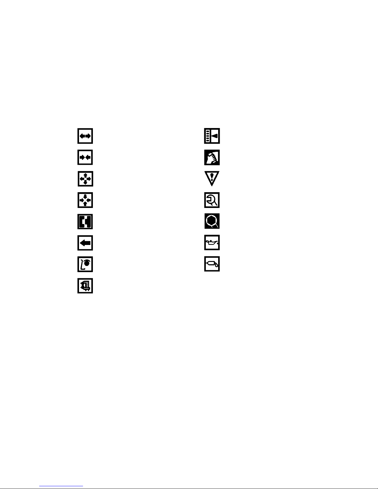
In this manual, the following symbols are used to indicate the type of service operations to be performed.
Removal
Installation
Disassembly
Reassembly
Align the marks
Directional Indication
Inspection
Measurement
Adjustment
Cleaning
Pay close attention-Important
Tighten to specified torque
Use special tools of manufacturer's
Lubricate with oil
Lubricate with grease
If you have any question or recommendation in connection with this manual, please do not hesitate to contact our
head office, dealers or authorized service shops.

CONTENTS
1. GENERAL INFORMATIONS 1
1.1. General Repair Instructions 1.4. Major Parts Fixing Bolts
1.2. Engine Specifications 1.5. Engine Repair Kit
1.3. Torque Specifications 1.6. Repair
2. ENGINE ASSEMBLY 19
2.1. General Description 2.3. Inspection and Repair
2.2. Disassembly 2.4. Reassembly
3. LUBRICATING SYSTEM 61
3.1. General Description 3.3. Oil Filter
3.2. Oil Pump 3.4. Oil Cooler
4. COOLING SYSTEM 66
4.1. General Description 4.3. Thermostat
4.2. Water Pump
5. FUEL SYSTEM 70
5.1. General Description 5.3. Injection Nozzle
5.2. Fuel Filter
6. SPECIAL TOOL LIST 74
•
WORLDWIDE NETWORK

1
1. GENERAL INFORMATION
1.1. General Repair Instructions
1. For safety, park the truck on even ground or work station and fix the wheels using wedges and hand brake
during operation.
2. Before performing service operations, disconnect the grounding cable from the battery to reduce the chance
of cable damage and burning due to short-circuiting.
3. Before performing service operations release the air pressure in the machine air line system for safety. To not
do so is extremely dangerous.
4. Use covers to prevent the components from damage or pollution.
5. Brake oil and anti-freeze solution must be handled with reasonable care as they cause paint damage.
6. The use of proper tools and special tools where specified is important for efficient and reliable service
operation.
7. Use genuine DAEWOO parts exclusively.
8. Used cotter pins, gaskets, O-rings, oil seals, lock washers and self-lock nuts should be discarded and new
ones should be prepared for installation as normal function of the parts can not be maintained if these parts
are reused.
9. To facilitate proper and smooth reassembly operation, keep disassembled parts neatly in groups. Keeping
bolts and nuts separate is very important as they vary in hardness and design depending on the position of
installation.
10. Clean the parts before inspection or reassembly. Also clean oil ports, etc. using compressed air to make
certain they are free from restrictions.
11. Lubricate rotating and sliding faces of parts with oil or grease before installation.
12. When necessary, use a sealant on gaskets to prevent leakage.
13. Carefully observe all specifications for bolts and nuts torques.
14. When a service operation is completed, make a final check to ensure that the service has been done
properly.

2
1.2. Engine Specifications
Engine Model
Items
Engine type Water-cooled, 4 cycle in-line, overhead valve type
Combustion chamber type Direct injection type
Cylinder liner type Dry type, casting liner
Timing gear system Gear drive type
No. of piston ring Compression ring 2, oil ring 1
No. of cylinder-bore
¡¿stroke (mm) 4-102¡¿100
Total piston displacement (cc) 3,268 (199 cu in)
Compression ratio 17.5 : 1
Engine dimension(length¡¿width¡¿height) (mm) 795¡¿701¡¿720 (31¡¿28¡¿28 in)
Engine weight(dry) (kg) 340 (750 lbs)
Fuel injection order 1-3-4-2
Fuel injection timing(B.T.D.C static) 13
¡˘
Type of fuel used High-speed diesel fuel (SAE No.2)
Injection pump type VE (DOOWON)
Governor type Mechanical governing
Injection nozzle type Multi-hole type (6 hole) - VCO nozzle
Fuel injection pressure (Kg/cm
2
) 220 (3,128 psi)
Compression pressure (kg/cm
2
) 30 (at 200 RPM) (426 psi)
Low idle speed (R.P.M) 775-825
High idle speed (R.P.M) 2400-2500
Intake and exhaust valve clearance(at cold) (mm) 0.4
Lubrication method Pressurized circulation
Oil pump type Gear type
Oil filter type Full-flow type
Lubricating oil capacity (
§⁄) 7.5 (Oil pan) (1.97 gal)
Oil cooler type Water cooled
Cooling method Pressurized circulation
Cooling water capacity(engine only) (§⁄) 7.5 (1.97 gal)
Thermostat type Wax pallet type (with jiggle valve)
Generator voltage-capacity(V-A) 12-61
Starter Voltage-output(V-KW) 12-2.5
Intake valve
Exhaust valve
Open at 28 (B.T.D.C)
Close at 62 (A.B.D.C)
Open at 70 (B.B.D.C)
Close at 28 (A.T.D.C)
DB 33A
3
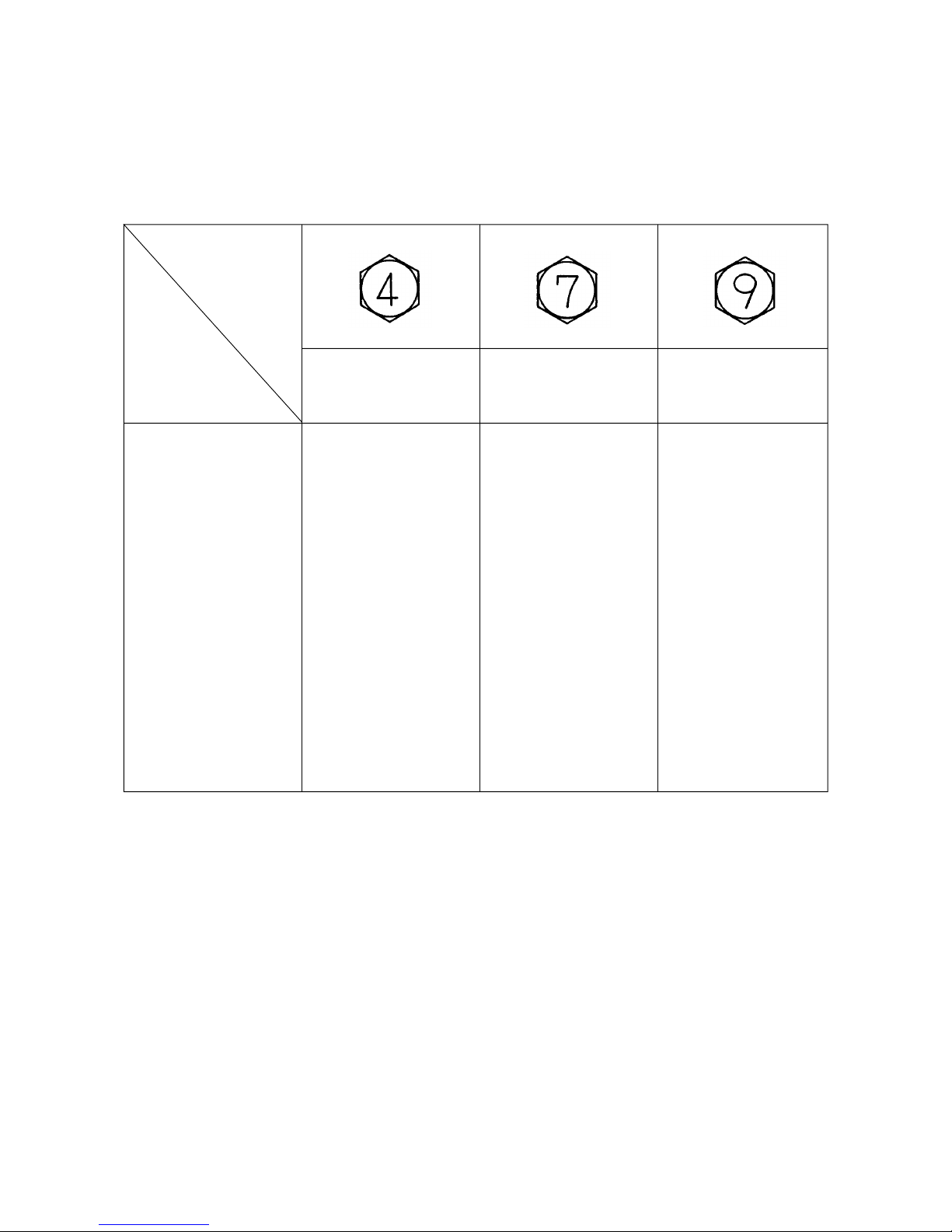
1.3. Torque Specifications
¡
Standards bolts
The torque values given in the following table should be applied where a particular torque is not specified.
(Unit : kgƒUm)
Bolt
identification
Bolt
diameter¡¿pitch
4T
Low carbon steel
7T
High carbon steel
9T
Alloy steel
6¡¿1.0
8¡¿1.25
10¡¿1.25
¡ 10¡¿1.5
12¡¿1.25
¡ 12¡¿1.75
14¡¿1.5
¡ 14¡¿2.0
16¡¿1.5
¡ 16¡¿2.0
18¡¿1.5
20¡¿1.5
22¡¿1.5
24¡¿2.0
0.4-0.8
0.8-1.8
2.1-3.5
2.0-3.4
5.0-7.5
4.6-7.0
7.8-11.7
7.3-10.9
10.6-16.0
10.2-15.2
15.4-23.0
21.0-31.6
25.6-42.2
36.6-55.0
0.5-1.0
1.2-2.3
2.8-4.7
2.8-4.6
6.2-9.3
5.8-8.6
9.5-14.2
9.0-13.4
13.8-20.8
13.2-19.8
19.9-29.9
27.5-41.3
37.0-55.5
43.9-72.5
-
1.7-3.1
3.8-6.4
3.7-6.1
7.7-11.6
7.3-10.9
11.6-17.4
10.9-16.3
16.3-24.5
15.6-23.4
23.4-35.2
32.3-48.5
43.3-64.9
56.5-84.7
The ¡indicates that the bolts are used for female-threaded parts that are made of soft materials such as casting, etc.
4
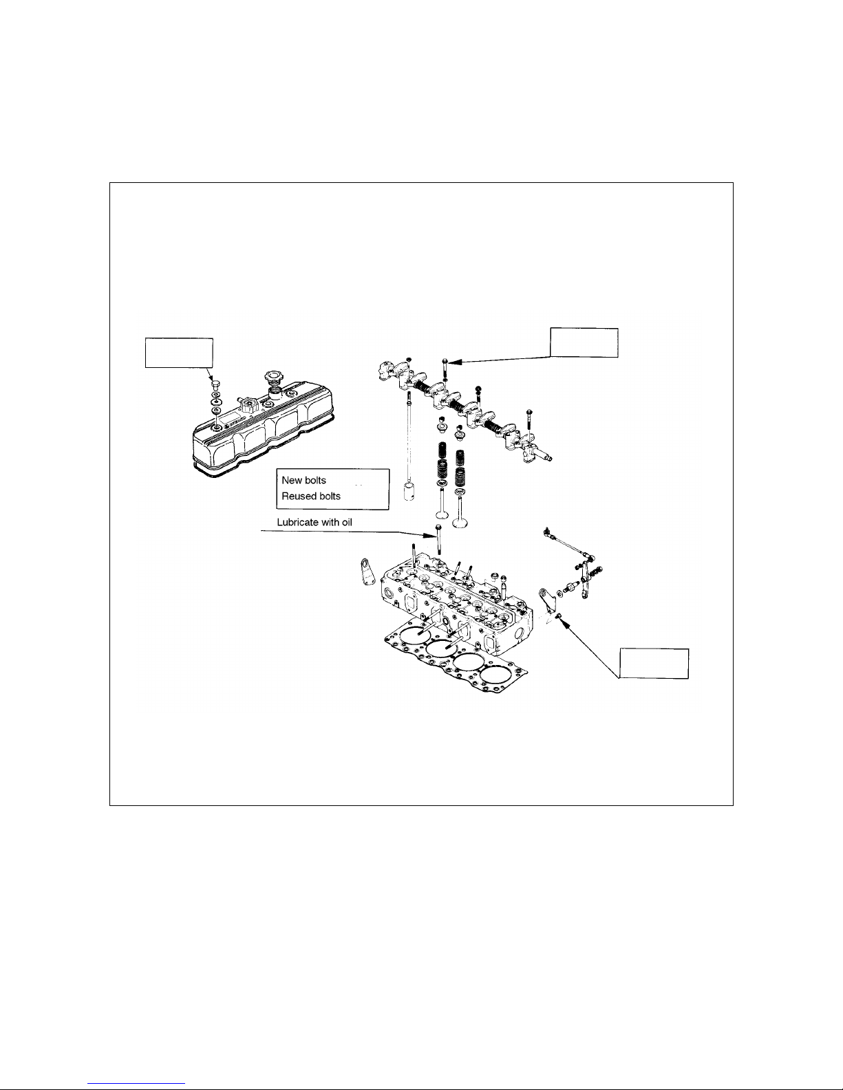
1.4. Major Parts Fixing Bolts
¡
Cylinder head and block
(unit : kgƒUm)
15.2 lb¡⁄ft
2.1
10.0
11.5
2.5
5.3
72.32 lb¡⁄ft
83.17 lb¡⁄ft
18.0 lb¡⁄ft
38.33 lb¡⁄ft
5
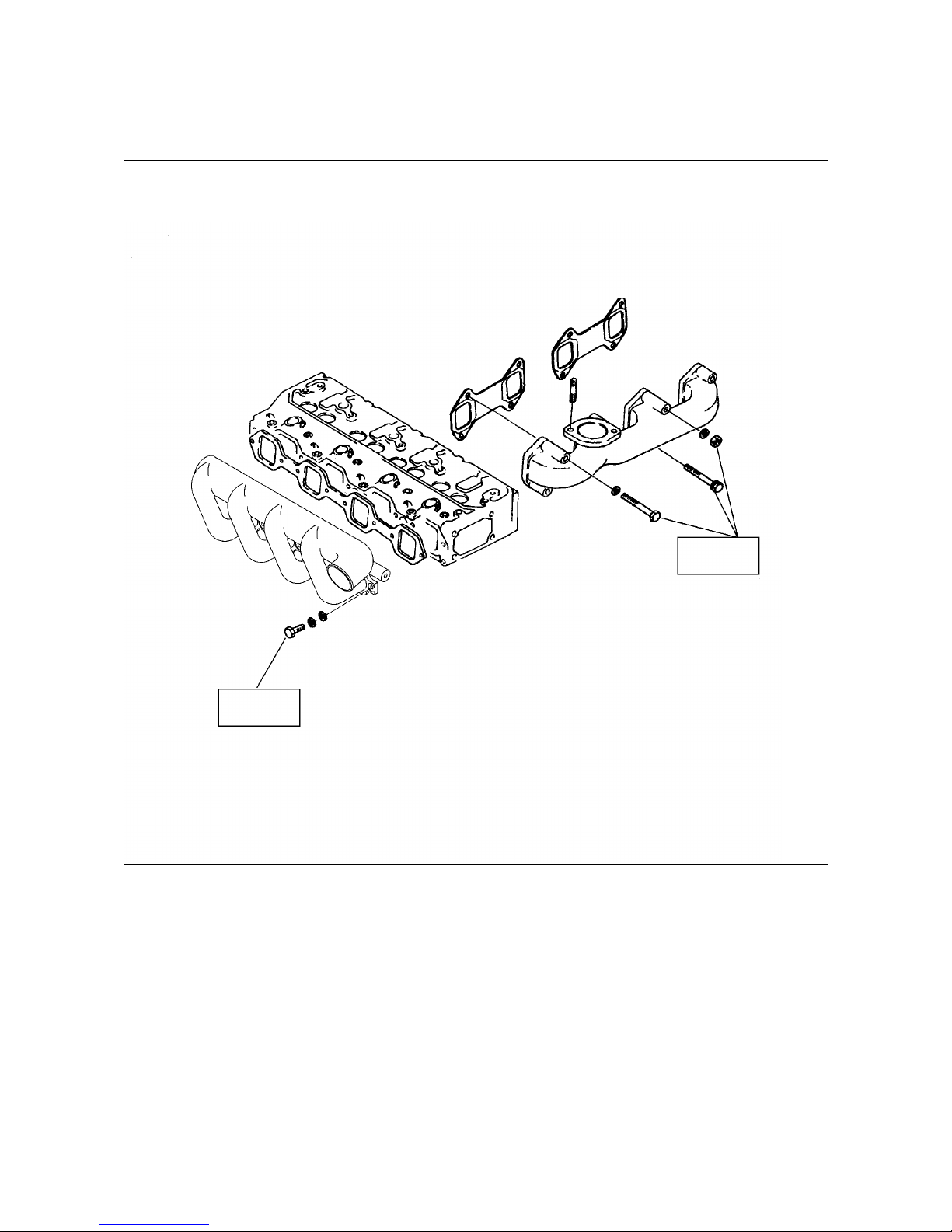
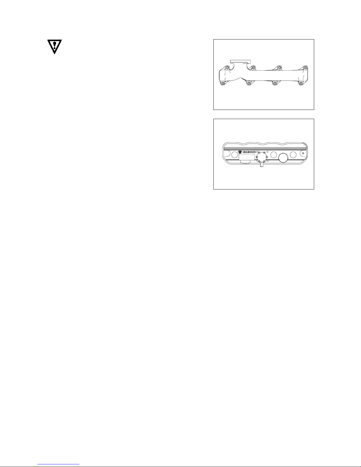
¡
Intake and exhaust manifold
(unit : kgƒUm)
15.2 lb¡⁄ft
2.1
2.1
15.2 lb¡⁄ft
6
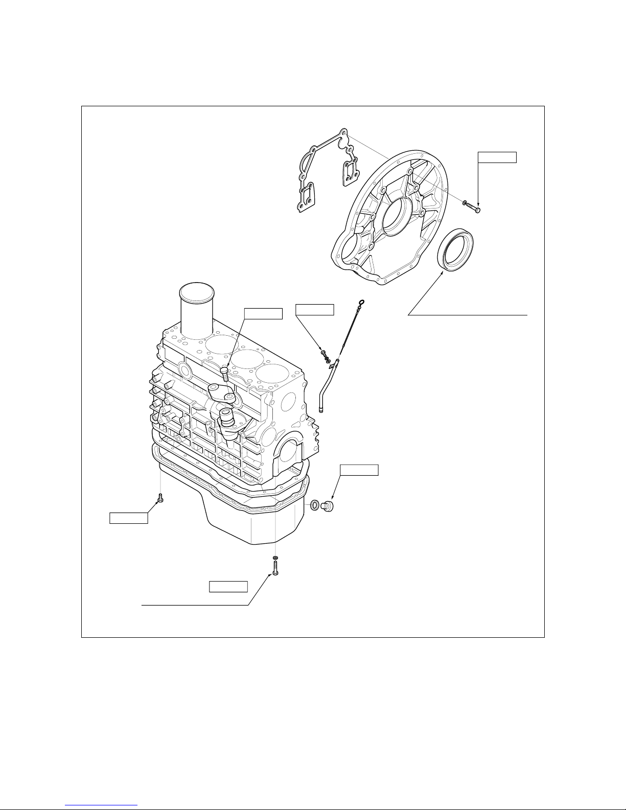
¡ Cylinder block and others
(unit : kgƒUm)
2.1
2.6
7.9
2.6
2.4
13.7
Lubricate with engine oil
Lubricate with engine oil
99.1 lb¡⁄ft
15.2 lb¡⁄ft
18.8 lb¡⁄ft
18.8 lb¡⁄ft
57.0 lb¡⁄ft
7
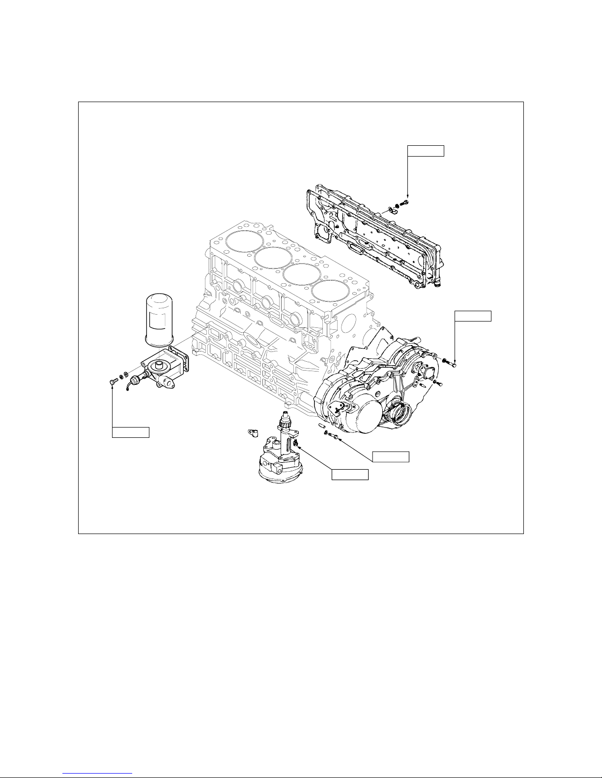
¡ Cylinder block and others
(unit : kgƒUm)
2.6
2.6
2.6
5.3
5.3
38.3 lb¡⁄ft
38.3 lb¡⁄ft
18.8 lb¡⁄ft
18.8 lb¡⁄ft
18.8 lb¡⁄ft
8
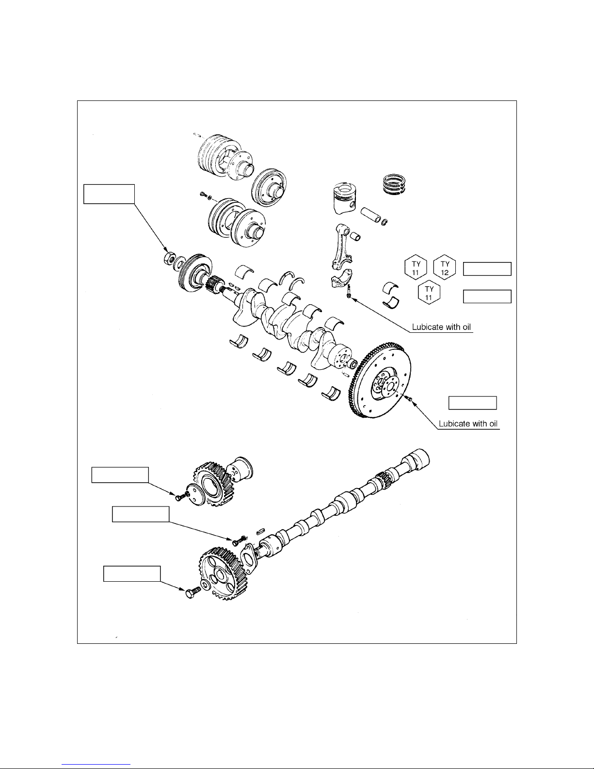
¡ Crankshaft and camshaft
(unit : kgƒUm)
44.0
5.5
2.5
16.0
16.0
12
¡ 0.25
9.75¡ 0.25
318 lb¡⁄ft
39.8 lb¡⁄ft
18.1 lb¡⁄ft
115.7 lb¡⁄ft
115.7 lb¡⁄ft
70.5
¡ 1.8
lb¡⁄ft
86.8
¡ 1.8
lb¡⁄ft
9
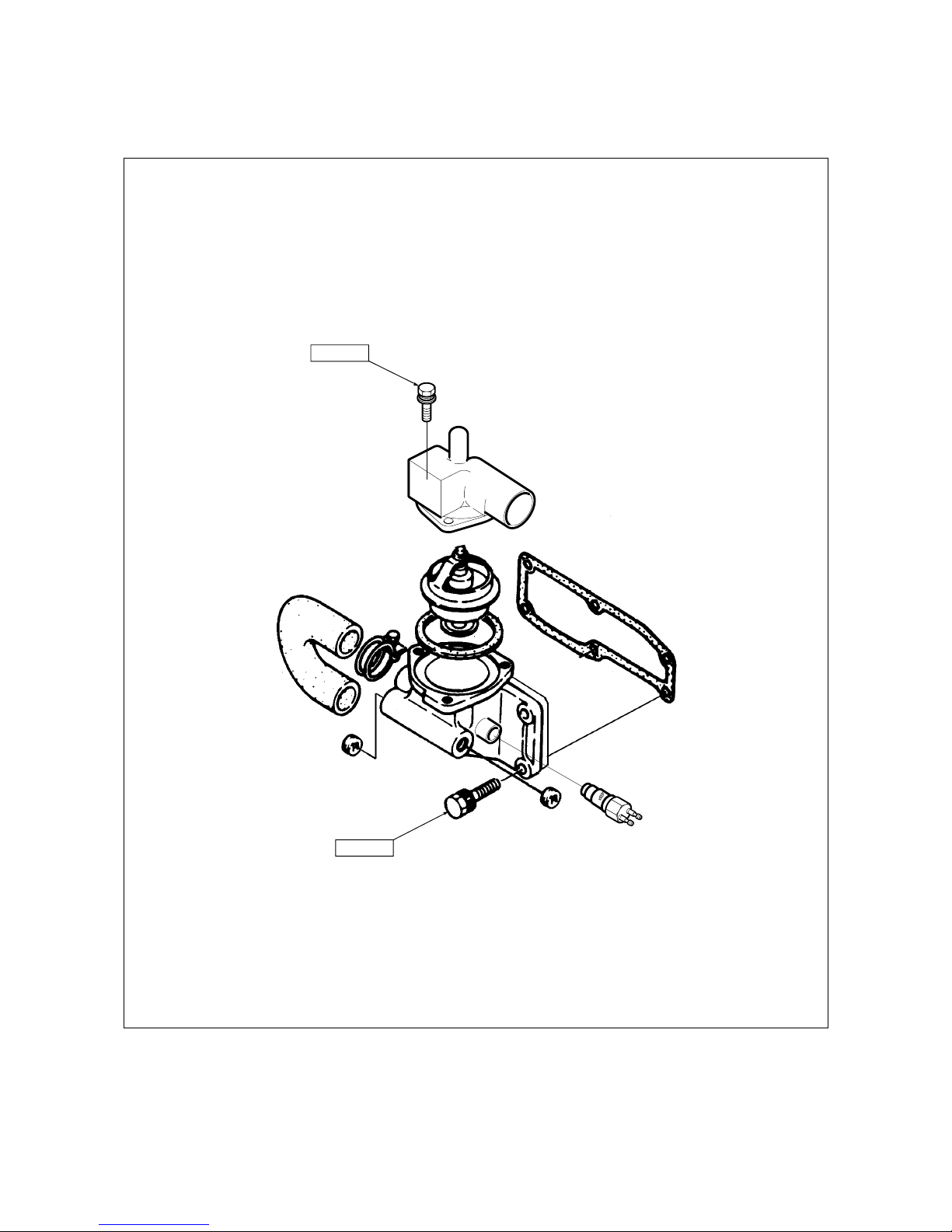
¡ Thermostat and housing
(unit : kgƒUm)
2.1
5.3
25.1 lb¡⁄ft
10.5 lb¡⁄ft
10
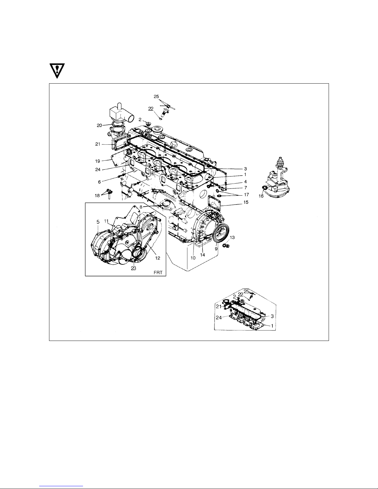
1.5. Engine Repair Kit
Part No. 1¡›25 : Engine disassembly components
Part No. 1, 3, 21, 22, 25 : Engine top disassembly components
1. Gasket : Cylinder head
2. Gasket : Cylinder head cover and bolt
3. Gasket : Head cover
4. Gasket : Relief valve
5. Gasket : Injection pump
6. Gasket : Tappet chamber and bolt
7. Gasket : Oil cooler
8. Gasket : Oil pump cover
9. Oil seal : Crankshaft(RR)
10. Gasket : Retainer
11. Gasket : Case and cylinder block
12. Gasket : Cover and case
13. Gasket : Oil pan drain plug
14. Gasket : Oil pan and body
15. Gasket : Oil filter
16. Gasket : Oil pump and pipe
17. Gasket : Oil filter pipe
18. Gasket : Oil jet pipe
19. Gasket : Water pump
20. Gasket : Outlet pipe
21. Gasket : Thermostat housing
22. Gasket : Nozzle gasket
23. Oil seal : Crank gear case
24. Gasket : Exhaust manifold
25. Gasket : Injection nozzle
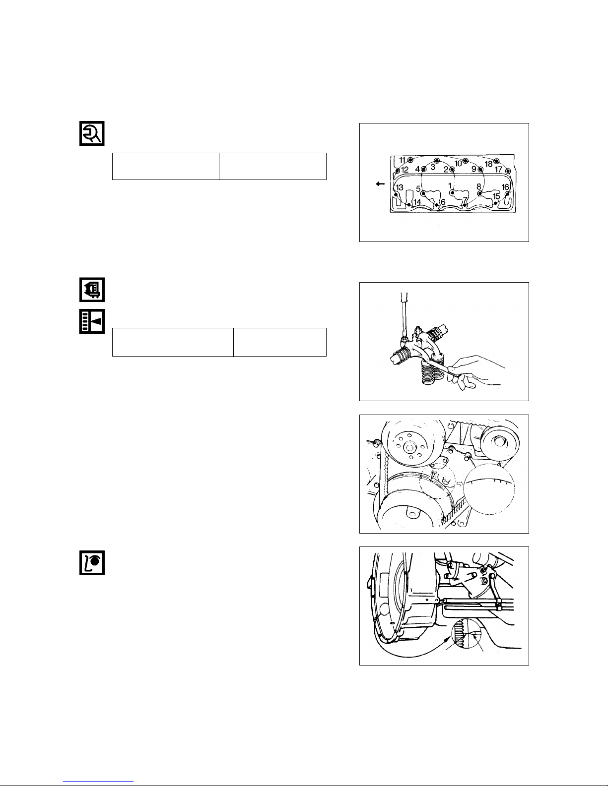
1.6. Repair
1.6.1. Cylinder Head Bolt
Tighten the cylinder head bolts in sequence as shown
in the figure.
11
Torque(kgƒUm)
11.5
( 83.2 lb¡⁄ft)
1.6.2 Valve Clearance
Adjust the valve clearance in the following manner
using a feeler gauge.
Standard(in cold)
Intake and exhaust (mm)
0.4
(.016 in)
1. Bring the piston in either the No. 1 cylinder or the No.
4 cylinder to top dead center on the compression
stroke by turning the crankshaft until the TDC notched
line on the crankshaft pulley is aligned the timing
pointer.
2. Check to see if there is play in the No. 1 intake and
exhaust valve rocker arms.
If the No. 1 cylinder intake and exhaust valve rocker
arms are depressed, the No. 4 piston is at TDC on the
compression stroke.
The same results can be obtained by using the TDC
line on flywheel and pointer.
Front
TDC
TDC line
Timing pointer
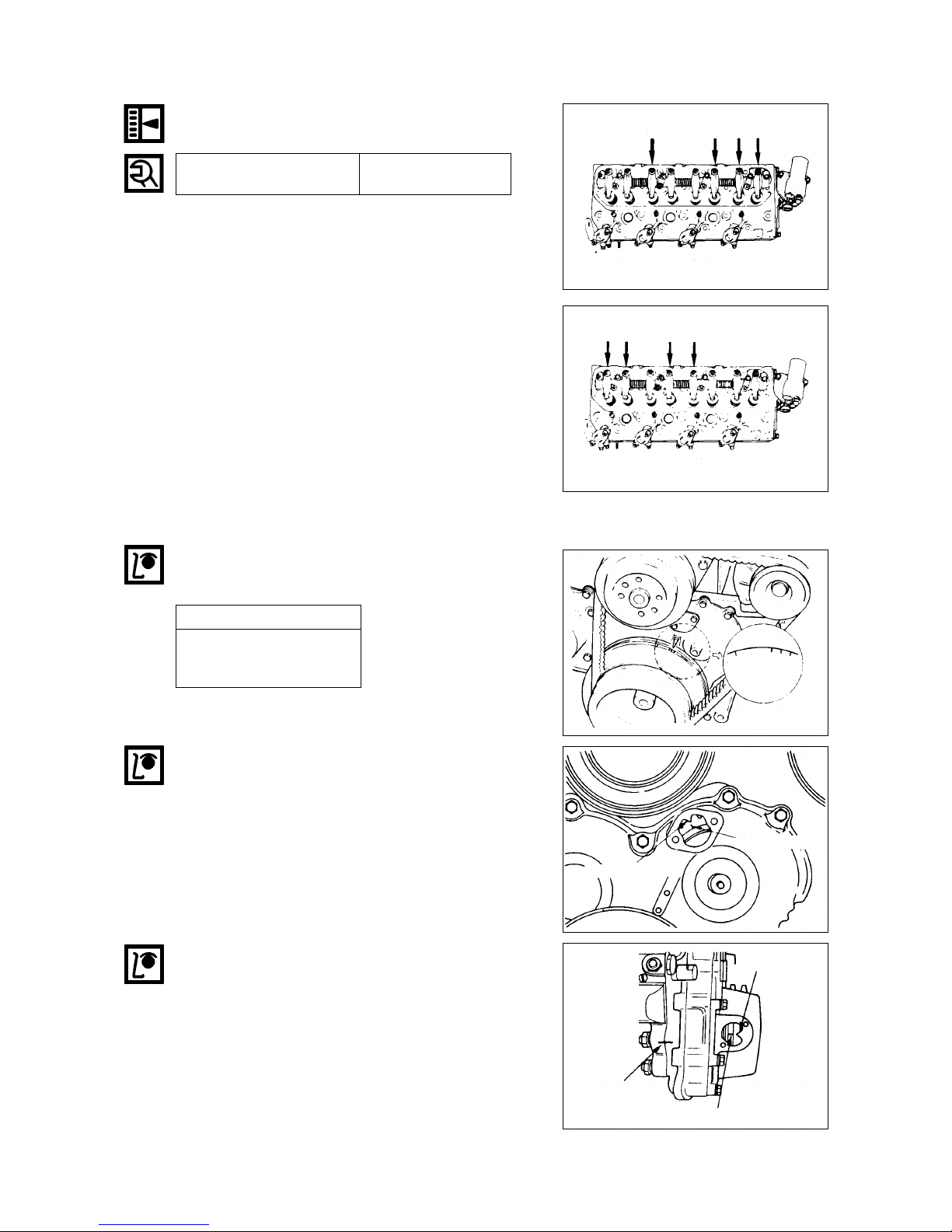
12
Adjust the clearances of valves marked with an
arrow
After adjusting the valve clearances referring to the
drawing, turn the crankshaft one full turn in the
rotative direction and align the TDC mark with the
pointer, then adjust the remaining valve clearances.
1.6.3. Injection Timing
Inspection
Check the notched line on the crankshaft pulley and
timing pointer are aligned.
Remove the inspection hole cover at the front of gear
case cover.
Check the alignment between the notched line on the
camshaft gear and the arrow mark of gear case cover.
Setting Timing (BTDC)
Engine : 13¡˘BTDC
I/P : Plunger Lift 0.3mm
(.0118 in)
Rocker arm screw 2.5
lock nut torque (kgƒUm) (18.1 lb¡⁄ft)
Check the notched line on the injection pump is in
alignment with the notched line on the timing gear
cover.
Check the alignment of the notched lines injection
pump and bracket.
TDC
Arrow mark
Notched line
Arrow mark
Notched line
Notched line
13
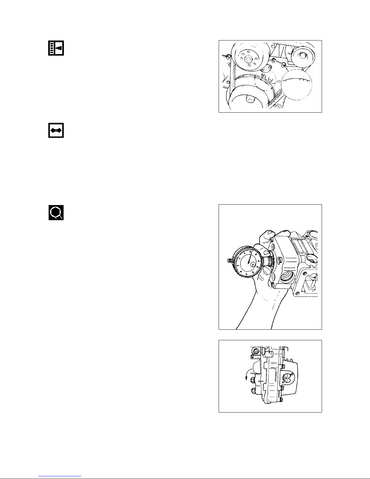
Injection timing adjustment
1. Adjust fuel injection timing with crank pulley
notched line and timing pointer.
Adjust the timing pointer with the marking on the
pulley.
2. Remove 2 fixing bolts of timing flange and injection
pump.
Remove bolt located at the center.
Insert the dial gauge to check the plunger lift.
Disconnect the inj. pipes (4pieces) from I/P
TDC
3.Turn the timing flange to adjust the plunger lift to
0.3mm.

14
Air cleaner
service
indicator
Stop button
4. Install the No. 1 injection pipe and tighten to
specified torque.
Do not overtighten the delivery valve holder. It will
distort the injection pump body shape and adversery
affect control rack operation.
Injection pipe nut torque (kgƒUm)
3¡›3.5
(21.7~25.3 lb¡⁄ft)
1.6.4. Compression Pressure
Remove the glow plugs from all cylinders, then check
the compression pressure in each cylinder with a
compression gauge by engaging starter.
(kg/cm
2
, 200 rpm)
Compression gauge adapter
Standard
30
Limit
22¡›23
(312~327 psi)
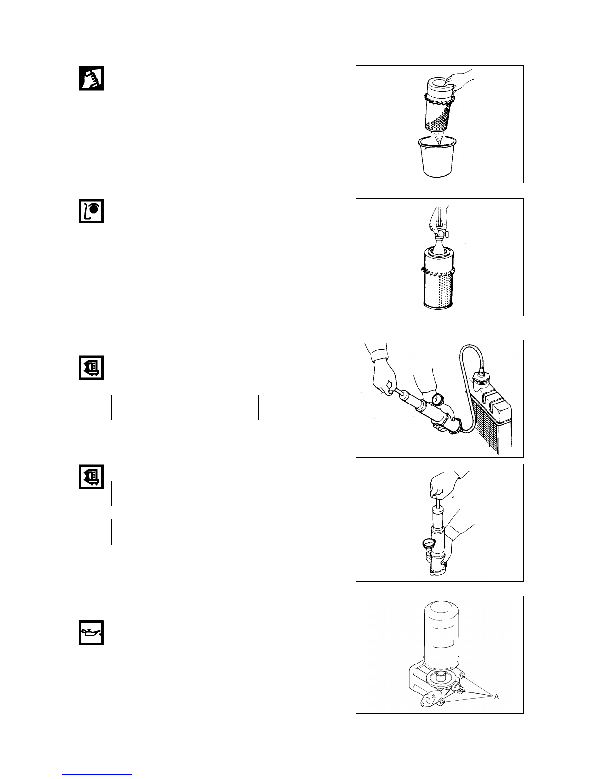
1.6.5. Air Cleaner
Dry type air cleaner
¡
Observe the air cleaner service indicator
¡
Clean the air cleaner element and dust pan when the
RED band in the service indicator looks in the visible
position.
Cleaning primary filter element
¡
Direct air inside of the element and blow out dusts
from the pleats completely.
(Maximum air pressure does not excess 2.1kg /cm
2
)
¡
Always replace the secondary element.
Do not attempt to reuse it by cleaning.
Compression gauge adapter
15
Detergent
¡
Wash the element in warm water and nonsudsing
household detergent.
¡
Rinse the element with clean water
¡
Dry it thoroughly with natural air or electric fan.
Don't use a flame or compressed air for drying. It
damages the element.
Checking element
¡
Insert a light inside the clean and dry element and
examine it.
¡
Discard the element if tears, rips or damages are
found.
¡
Wrap and store good elements in a clean, dry place.
1.6.6. Radiator
¡
Install the radiator cap tester and pressurize the
radiator.
¡
Inspect the cooling system if there any leak.
Measuring pressure (kg/cm2)
1.0
(14.2 psi)
Radiator cap
Pressure valve opening pressure (kg/cm2)
0.87
(12.4 psi)
Vaccum valve opening pressure (kg/cm2)
0.05
(.71 psi)
1.6.7. Lubricating System
Oil filter replacement
¡
Before installing a new filter element apply a small
amount of clean engine oil to the element gasket.
¡
Install the new element. When the gasket contacts
the base, tighten it 3/4 of a turn more.
Do not overtighten.
Element
16
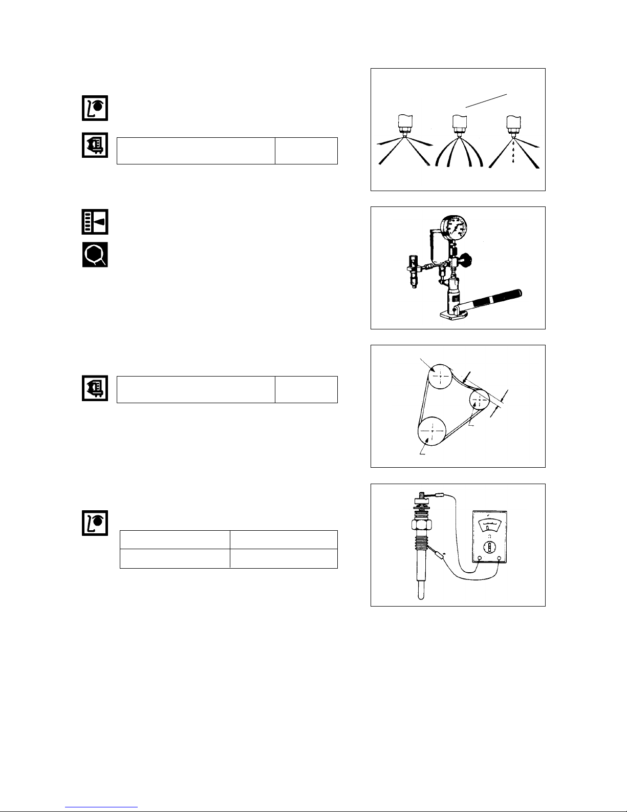
1.6.8. Fuel System
Injection nozzle
Check the spraying condition and injection starting
pressure.
Adjustment
Adjust the injection starting pressure with the
adjusting screw using a nozzle tester.
Incorrect
Incorrect
Correct
1.6.9. Fan Belt
(mm)
Fan pulley
Depress here
Generator pulley
Crank pulley
1.6.10. Glow Plug
Inspection(Resistance)
Check the continuity across the plug terminals and
body.
Silver color
Black color
4.5 §
1.6§
Injection starting pressure (kg/cm2)
220
(3.128 psi)
Specified belt deflection
10
(.393 in)
17
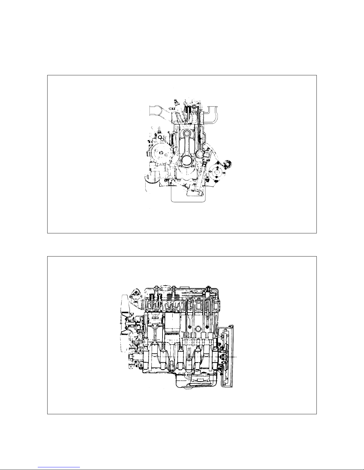
2. Engine Assembly
2.1. General Description
18
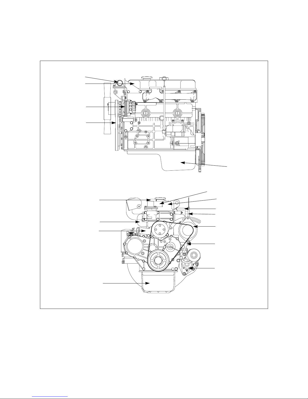
2.2. Disassembly
2.2.1. External Parts (A)
<Disassembly steps>
1. Breather hose
2. Exhaust manifold
3. Oil guide tube and level gauge
4. Starter
5. Cooling fan belt
6. Alternator
7. Oil pan
8. Cylinder head cover
9. Rubber hose
10. Water pump
11. Thermostat housing assembly
11
8
6
12
11
8
2
3
6
5
4
7
10
9
1
5
19
1864
2753
132
Important operations
¡
Exhaust manifold assembly(2)
Loosen the manifold fixing bolts in sequence of
figure's shown.
¡
Cylinder head cover(8)
Loosen the head cover bolts in sequence of figure's
shown
20
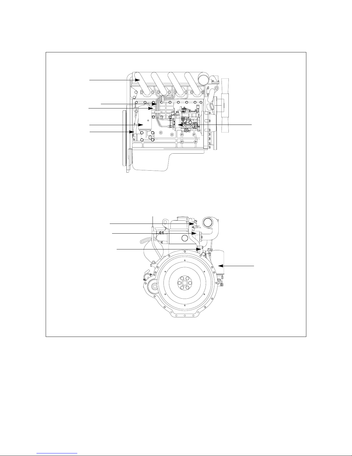
2.2.2. External Parts (B)
<Disassembly steps>
1. Fuel injection pipe
2. Injection nozzle
3. Glow plug
4. Intake manifold
5. Oil pipe
6. Oil filter assembly
7. Injection pump
8. Oil cooler assembly
7
8
6
5
2
6
3
8
4
1
 Loading...