

Doosan D40SC-5, D55C-5, D45SC-5, D50SC-5, D55SC-5 Disassembly/assembly
...
Vehicle System
Disassembly & Assembly
D35S-5, D40S-5, D45S-5, D50C-5, D55C-5
D40SC-5, D45SC-5, D50SC-5, D55SC-5
G35S-5, G40S-5, G45S-5, G50C-5, G55C-5
G40SC-5, G45SC-5, G50SC-5, G55SC-5
GC35S-5, GC40S-5, GC45S-5
GC50C-5, GC55C-5
SB4267E00
May. 2007

1
WARNING
Important Safety Information
Most accidents involving product operation, maintenance and repair are caused by failure to observe basic
safety rules or precautions. An accident can often be avoided by recognizing potentially hazardous situations
before an accident occurs. A person must be alert to potential hazards. This person should also have the
necessary training, skills and tools to perform these functions properly.
Read and understand all safety precautions and warnings before operating or performing lubrication,
maintenance and repair on this product.
Basic safety precautions are listed in the “Safety” section of the Service or Technical Manual. Additional safety
precautions are listed in the “Safety” section of the owner/operation/maintenance publication.
Specific safety warnings for all these publications are provided in the description of operations where hazards
exist. WARNING labels have also been put on the product to provide instructions and to identify specific
hazards. If these hazard warnings are not heeded, bodily injury or death could occur to you or other persons.
Warnings in this publication and on the product labels are identified by the following symbol.
Improper operation, lubrication, maintenance or repair of this product can be dangerous and could result in
injury or death.
Do not operate or perform any lubrication, maintenance or repair on this product, until you have read and
understood the operation, lubrication, maintenance and repair information.
Operations that may cause product damage are identified by NOTICE labels on the product and in this
publication.
DOOSAN cannot anticipate every possible circumstance that might involve a potential hazard. The warnings
in this publication and on the product are therefore not all inclusive. If a tool, procedure, work method or
operating technique not specifically recommended by DOOSAN is used, you must satisfy yourself that it is
safe for you and others. You should also ensure that the product will not be damaged or made unsafe by the
operation, lubrication, maintenance or repair procedures you choose.
The information, specifications, and illustrations in this publication are on the basis of information available at
the time it was written. The specifications, torques, pressures, measurements, adjustments, illustrations, and
other items can change at any time. These changes can affect the service given to the product. Obtain the
complete and most current information before starting any job. DOOSAN dealers have the most current
information available.


Vehicle Systems Index 3
Index
Disassembly & Assembly....................... 5
Hood (with seat) .................................................... 5
Overhead Guard.................................................... 6
Tilt Cylinders ......................................................... 7
Secondary Lift Cylinders........................................ 9
Primary Lift Cylinder ............................................ 12
Hydraulic Control Value ....................................... 15
Washing .............................................................. 17
Inspection............................................................ 17
Assembling.......................................................... 18
Relief Valve Maintenance .................................... 20
Steering Wheel .................................................... 29
Steering Unit ....................................................... 30
Brake Hydraulic Booster ...................................... 39
Tie Rods.............................................................. 43
Steering Knuckles, Kingpins, And Bearings ....... 44
Steer Axle............................................................ 45
Steering Cylinder ................................................. 46
Tires And Rims (Steer)........................................ 48
Hydraulic Control Valves...................................... 49
Hydraulic Pump ................................................... 50
General Instruction .............................................. 51
Disassembly Process .......................................... 51
Counterweight ..................................................... 56
Hydraulic Oil Filter Assembly............................... 57
Drive Axle and T/M .............................................. 57
Engine................................................................. 58
Disconnect batteries before performance of any
service work.
WARNING

Vehicle Systems Disassembly & Assembly 5
1
Disassembly & Assembly
Hood (with seat)
Remove & Install Hood (with seat)
Assembly
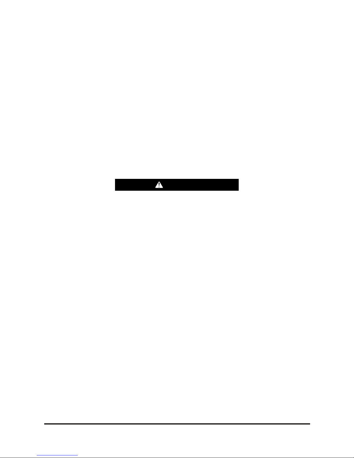
The hood and seat assembly can fall when nut
(1) is removed from the support cylinder rod. To
avoid personal injury, support the seat and hood
assembly before removing nut (1).
1. Raise the hood. Support the hood with a hoist.
2. Remove nut (1) from the support cylinder.
Remove the cylinder rod from the bracket.
3. Lower the hood.
4. Remove the bolts (2) from the cover. Remove
cover.
5. Remove the washers and four bolts (3).
6. Release latch (4). Use the hoist to remove hood
and seat assembly. The hood and seat assembly
weighs approximately 52 kg (115 lb).
7. Install the hood and seat assembly in the reverse
order of removal.
WARNING
2
3
4
Vehicle Systems Disassembly & Assembly 6
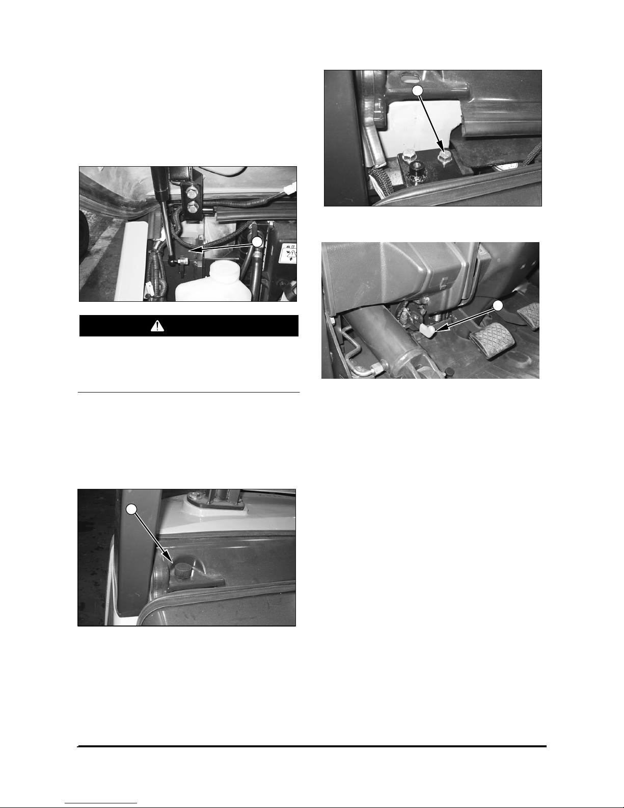
Overhead Guard
Remove & Install Overhead Guard
1. Support overhead guard (1) with lifting straps and
a hoist.
2. Remove the washers, nuts, and two bolts (2).
3. Remove the washers, nuts, and two bolts (3).
4. Remove front overhead guard (1), Front overhead
guard (1) weighs approximately 30 kg (66 lb).
5. Remove the washers, nuts, and four bolts (4).
6. Remove rear Leg (5).
7. Install front overhead guard (1) and rear leg (5) in
the reverse order of removal.
Vehicle Systems Disassembly & Assembly 7
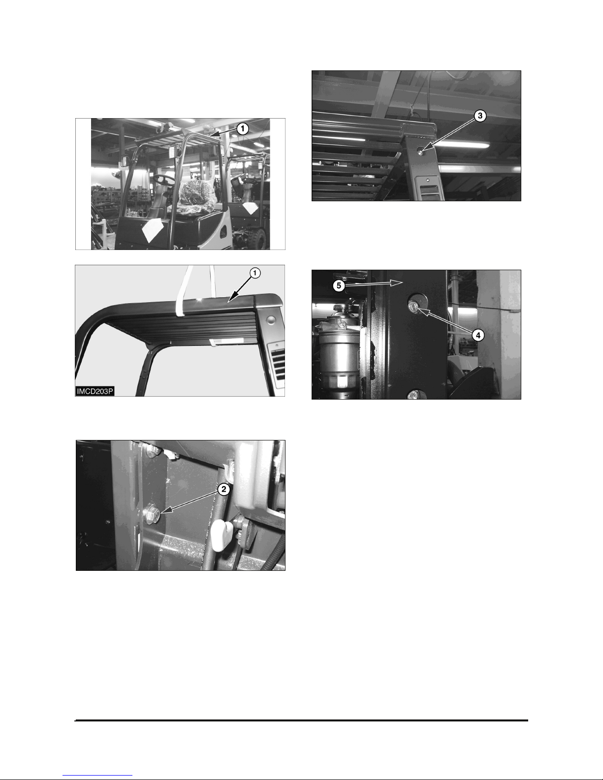
Tilt Cylinders
Remove & Install Tilt Cylinders
NOTE: The procedure for removing and installing
the tilt cylinders is the same for both cylinders.
If both tilt cylinders are removed at the same
time the mast can fall. To avoid possible
personal injury, make sure the mast is securely
held in place or supported by a hoist before
removing the tilt cylinders.
To prevent personal injury, move the control
levers backward and forward to release any
pressure in hydraulic system. Slowly loosen the
cap of the hydraulic tank to release any pressure
in the tank. Be cautious of hot hydraulic oil when
any lines are disconnected in the hydraulic
system.
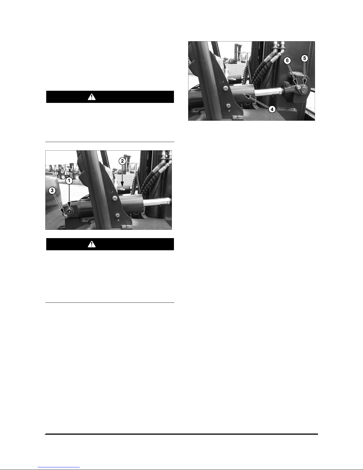
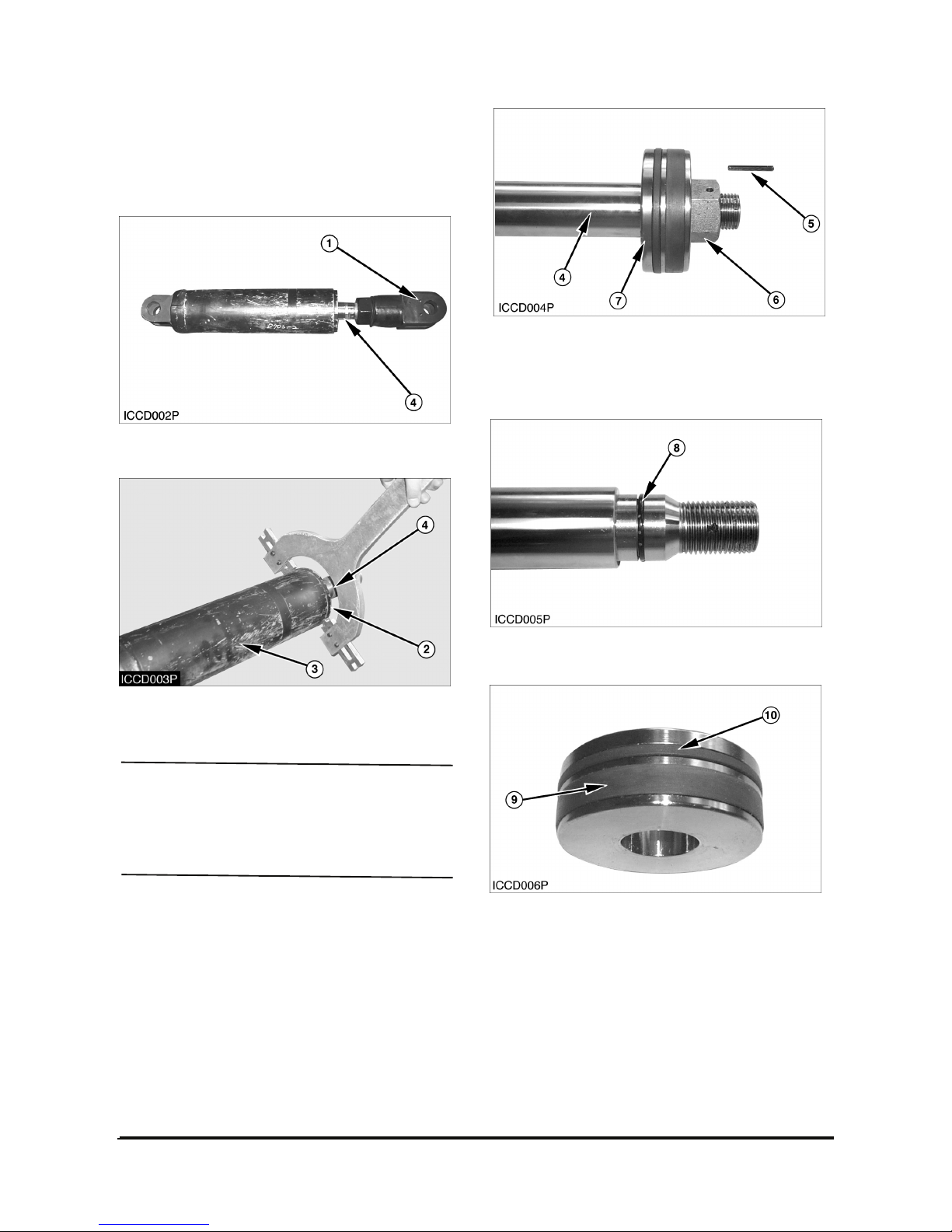
1. Disconnect elbow (2). Remove retainer bolt (3)
and pin (1).
2. Remove retainer bolt (6) from pin (5). Remove pin
(5).
3. Remove tilt cylinder (4).
4. Install the tilt cylinder in the reverse order of
removal.
WARNING
WARNING
Vehicle Systems Disassembly & Assembly 8
Disassemble & Assemble Tilt Cylinders
Start By:
a. Remove tilt cylinder.
1. Remove eye (1) from the rod assembly (4).
2. Remove rod cover (2) from the cylinder tube (3)
using a spanner wrench.
NOTICE
Use extra care not to damage the highly finished
surface of the cylinder rod and the bore of the
clylinder tube during disassembly and assembly of
the tilt cylinder.
3. Remove rod assembly (4) from the cylinder body.
4. Remove pin (5) inside hole and nut (6) from the
cylinder rod (4).
5. Remove piston (7) from the cylinder rod.
6. Remove O-ring seal (8) from the cylinder rod.
7. Remove wear ring (9) and slipper seal (10) from
the piston.
Vehicle Systems Disassembly & Assembly 9
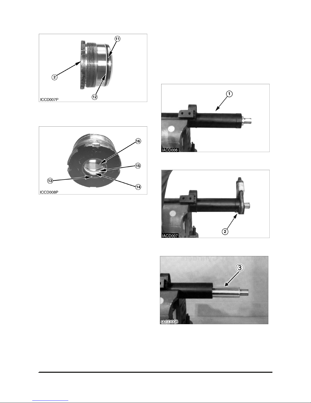
8. Remove O-ring seal (11) and backup ring (12)
from the rod cover (2).
9. Remove wiper seal (13), backup ring (14), Upacking (15) and DU-bush (16) from the rod cover.
NOTE: Assemble the tilt cylinder in the reverse
order of disassembly.
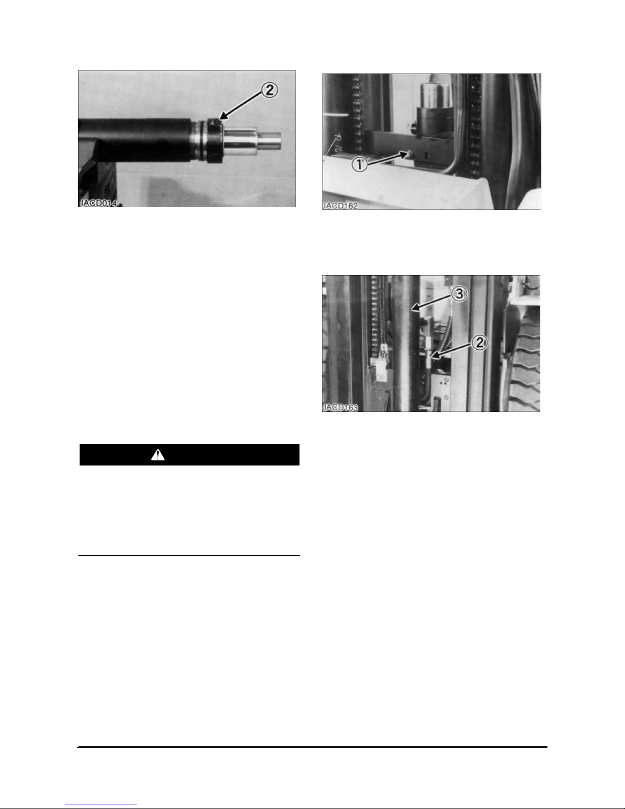
Secondary Lift Cylinders
Disassemble Secondary Lift Cylinders
Start By :
a. Remove secondary lift cylinders.
1. Put secondary lift cylinder (1) in position as shown.
2. Remove head assembly (2) with tool.
3. Remove rod (3) from the cylinder body.
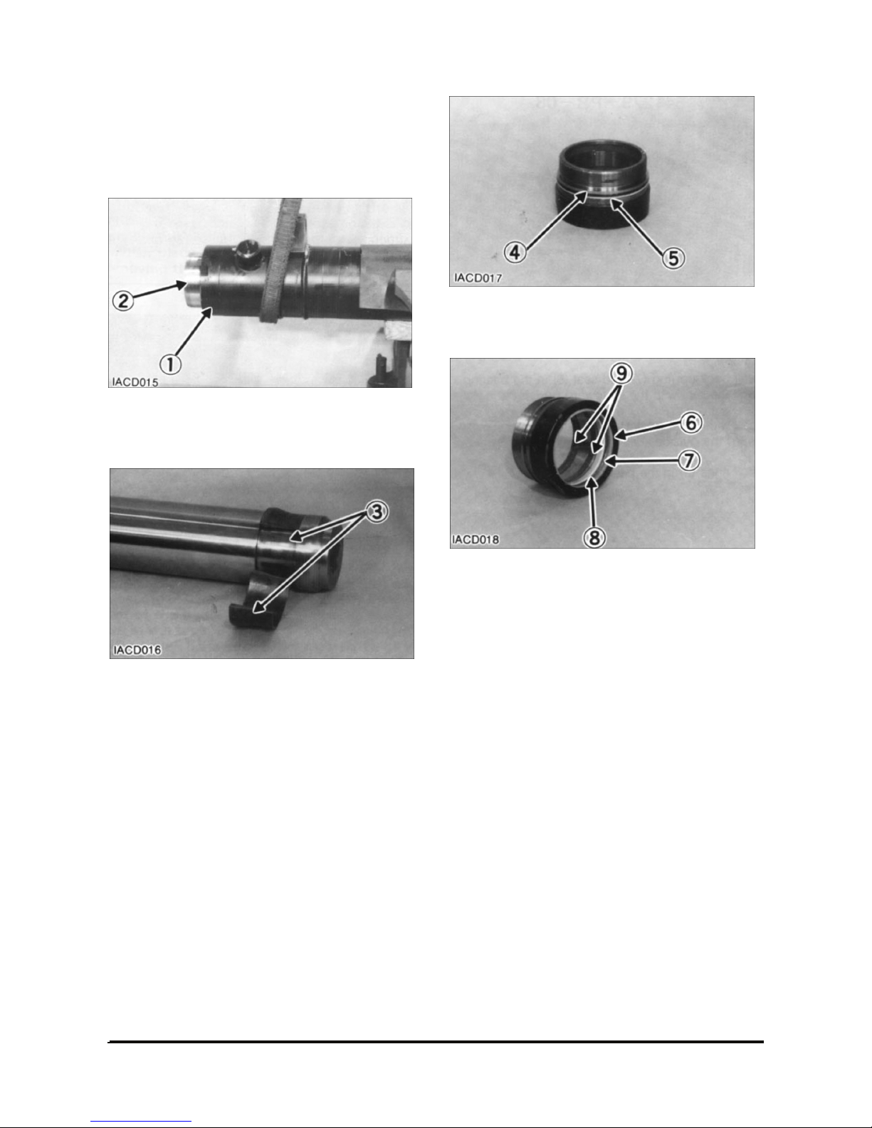
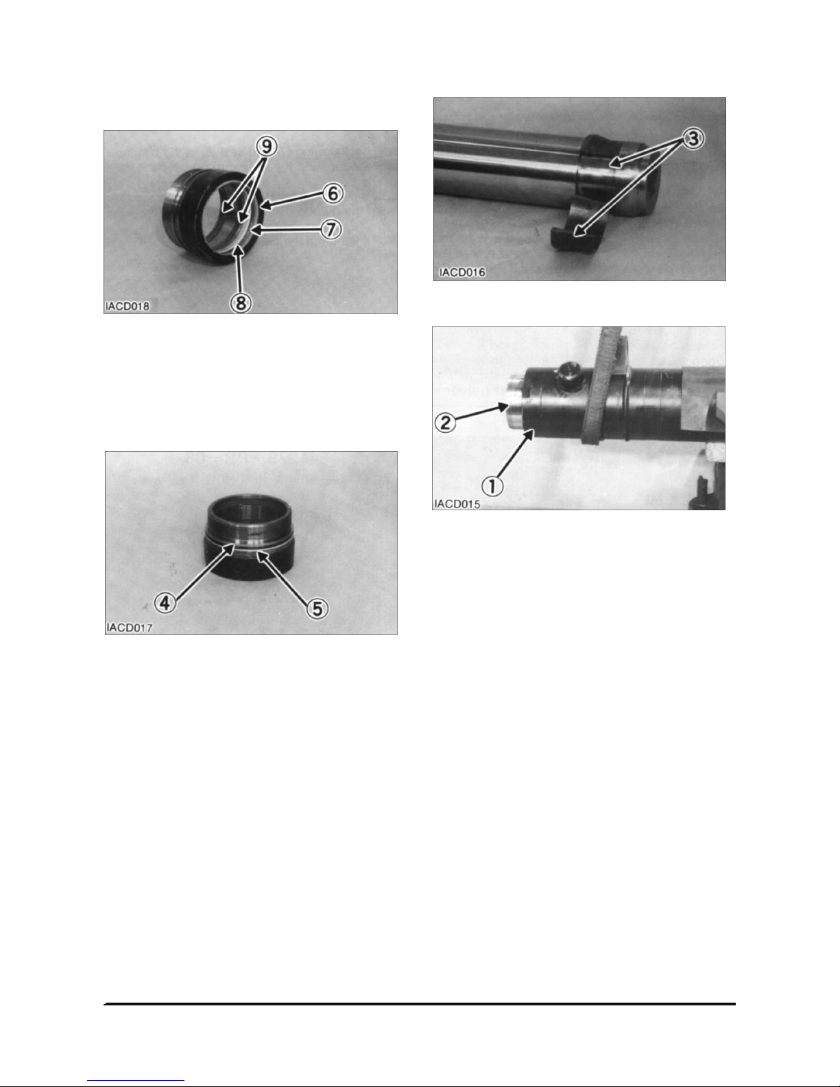
Vehicle Systems Disassembly & Assembly 10
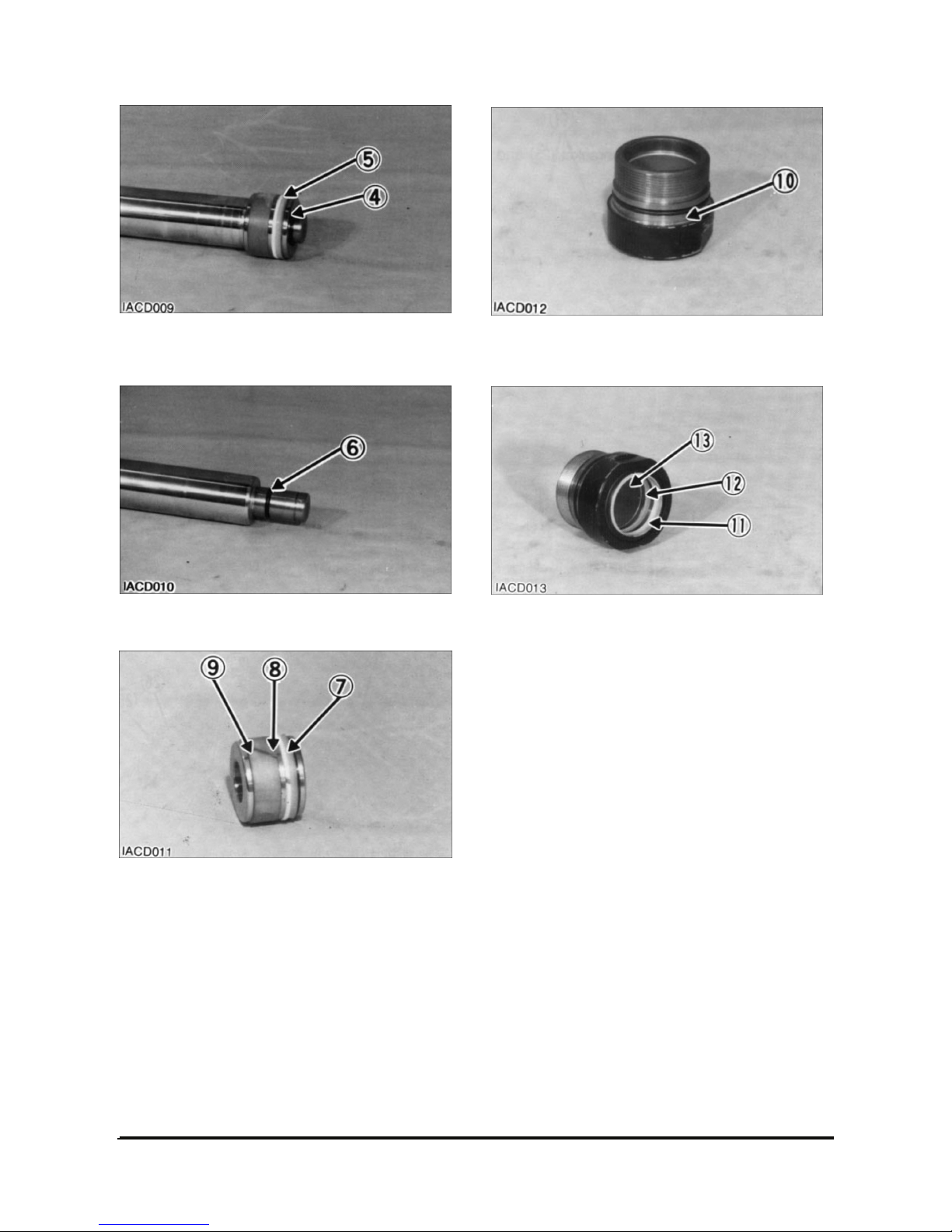
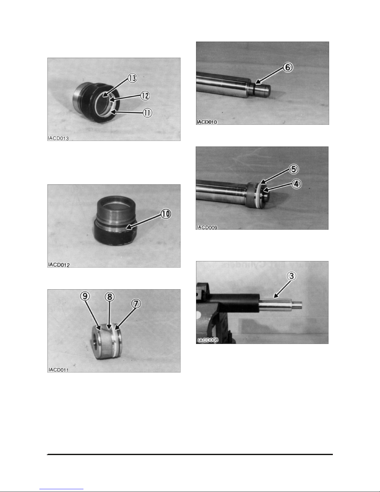
4. Remove retaining ring (4) and piston (5) from the
cylinder rod.
5. Remove O-ring seal (6) from the cylinder rod.
6. Remove O-ring seal (7), back-up ring (8) and seal
(9) from the piston.
7. Remove O-ring seal (10) from the head assembly.
8. Remove wiper seal (11), seal (12) and bush (13)
from the head assembly.
Vehicle Systems Disassembly & Assembly 11
Assemble Secondary Lift Cylinders
1. Install bush (13) and seal (12).
2. Install wiper seal (11). Install the seal with the lip
toward the outside.
3. Install O-ring seal (10) onto the head assembly.
4. Install seal (9), back-up ring (8) and O-ring seal
(7) on the piston.
5. Install O-ring seal (6) on the cylinder rod.
6. Install piston (5) and retaining ring (4) on the
cylinder rod.
7. Install cylinder rod (3) in the cylinder body.
Vehicle Systems Disassembly & Assembly 12
8. Install head assembly (2) on the cylinder rod and
tighten using tool.
End By :
a. Install secondary lift cylinders.
Primary Lift Cylinder
Remove & Install Primary Lift Cylinder
Start By :
a. Remove carriage.
To prevent personal injury, move the control
levers backward and forward to release any
pressure in hydraulic system. Slowly loosen the
cap of the hydraulic tank to release any pressure
in the tank. Be cautious of hot hydraulic oil when
any lines are disconnected in the hydraulic
system.
1. Fasten nylon straps and hoist to the primary lift
cylinder.
2. Remove bolt (1).
3. Pull the cylinder out far enough to disconnect
hydraulic hose (2). Remove primary lift cylinder
(3).
4. Install primary lift cylinder (3) in the reverse order
of removal.
End By :
a. Install carriage.
WARNING
Vehicle Systems Disassembly & Assembly 13
Disassemble Primary Lift Cylinder
Start By :
a. Remove primary lift cylinder.
1. Remove bearing (1).
2. Remove rod (2) from the cylinder body.
3. Remove split rings (3) from the cylinder rod.
4. Remove O-ring seal (4) and back-up ring (5) from
the bearing.
5. Remove wiper seal (6), back-up ring (7), seal (8)
and rings (9) from the bearing.
Vehicle Systems Disassembly & Assembly 14
Assemble Primary Lift Cylinder
1. Install back-up ring (7) and seal (8) in the bearing.
Install the seal with the lip toward the inside.
2. Install wiper seal (6). Install the seal with the lip
toward the outside.
3. Install rings (9) in the bearing.
NOTE: Install the back-up ring with the curved side
contacting the O-ring seal.
4. Install the back-up ring (5) and O-ring seal (4) on
the bearing.
5. Install split rings (3) on the cylinder.
6. Install cylinder rod (2) in the cylinder body.
7. Install bearing (1) on the cylinder body. Tighten
the bearing (1).
End By :
a. Install primary lift cylinder.
Vehicle Systems Disassembly & Assembly 15
Hydraulic Control Value
Disassembling
Keep following precautions for disassembling.
1. The main equipment has to be leveled, with all
the working units grounded, engine stopped, and
the actuator has to be depressurized. If
disassemble the actuator while it is pressurized,
high pressure oil or part may ejected out which is
very dangerous.
2. Release the air pressure in tank(for pressurized
tanks)
3. Clean up the surroundings of the part to be
disassembled, and take care that foreign matter
does not enter the valve.
4. Mark the disassembled parts or arrange them on
work bench in the order of assembly in order not
to confuse the order of assembling.
5. Replace all the seals(O-rings, back-up rings)
which were disassembled with new seals.
6. Since the spool is matched with the valve housing
by clearance control, it is not replaceable for
quality. Protect it from impact of falling down.
7. Protect the sealing faces of the fitting surfaces in
all sections from impact or scratch.
8. In order to minimize internal leak, the clearance of
spool is kept as small as possible. Disassembling
and assembling the spool may deform the spool.
Therefore, full assembly replacement, when
necessary, is recommended.
Refer to the attached Parts List for the dimensions
and torques of the screws and plugs related with the
disassembling.
Disassembling Valve Assembly
The assembling number shall be in compliance with
the attached Assembly Parts List: Representative
Parts No. C0240-41001.
1. Place the valve assembly on level work table, with
the mounting side down. Remove the nuts(1) and
(3) for the tie rod, at the end of the outlet section.
2. Slowly remove each spool section assembly in
the reverse order as in the outlet section.
Take care not to lose poppet, springs, or o-rings in
the fitting face of each section.
3. Remove the tie rods (2) & (4) from the inlet
section assembly.
Disassembling the Inlet Section
Assembly
The combination number shall be in accordance
with the attached Part List No. C0213-41001.
Fix the unit on the vise softly, covering the fitting
face of the inlet section assembly to prevent
damage.
1. Remove socket head bolt(14), remove cap(13),
and remove the spool(2) in sub-assembly state
from the inlet housing(1). The seal plate(5),
wiper(4), and O-ring(3) on the cap(13) side have
to be remain affixed to the spool(2)
【Cautions for Removing Spool 】
When removing the spool, take it out correctly to
prevent dent or scratch. Dent or scratch may harm
the housing hole when removing the spool, or may
make it impossible to reinsert the spool, or may
cause malfunction even able to be inserted. Each
spool has to be marked and arranged on work
bench, etc., to prevent confusion in reassembling. If
assembled wrong, the actuator will fail to operate
properly, which may cause serious danger.
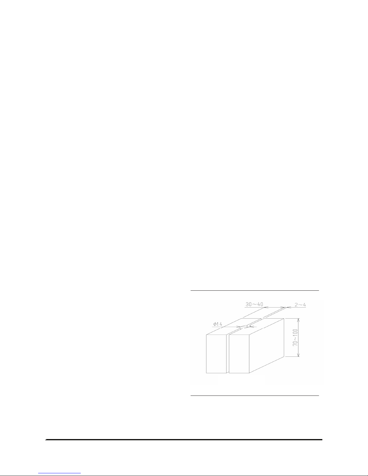
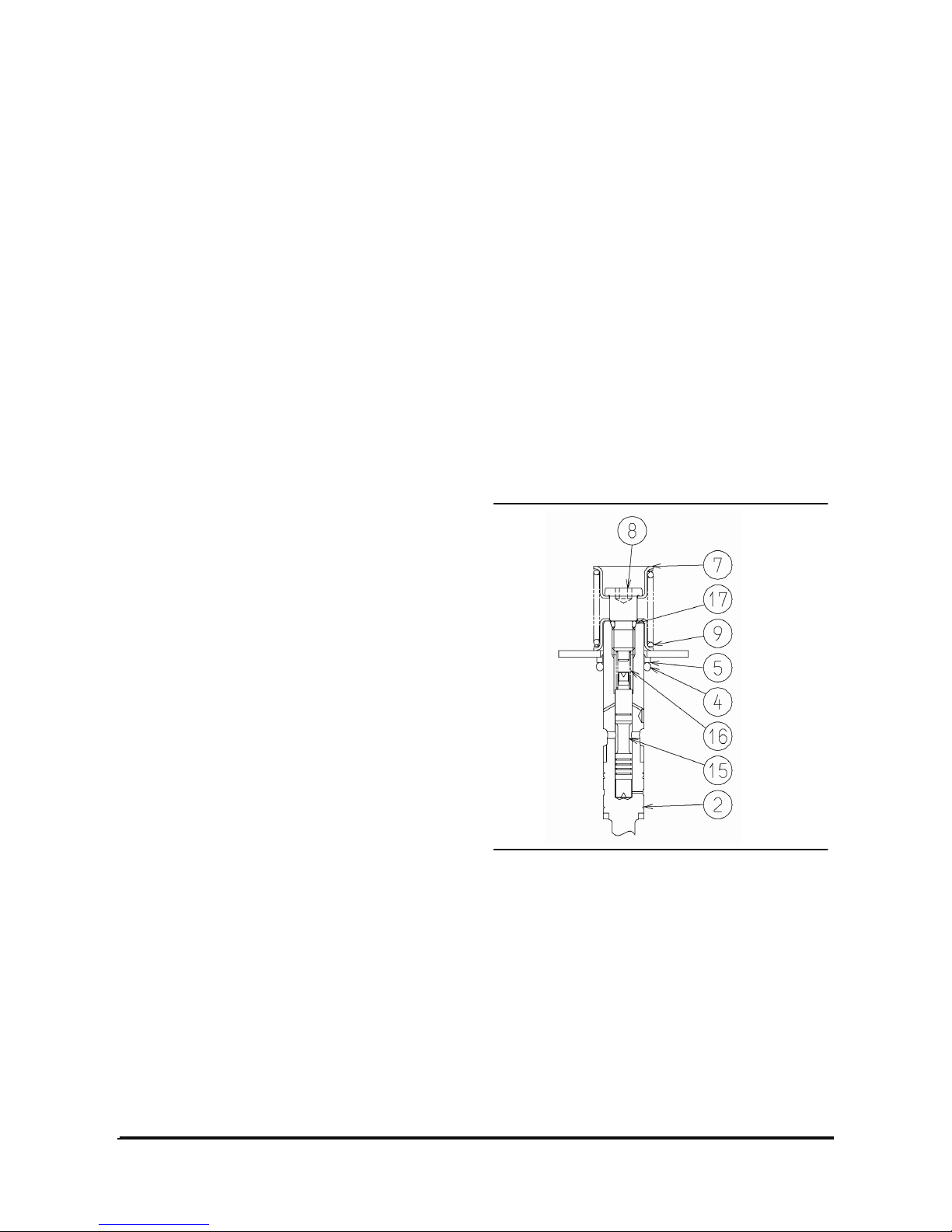
【Fig. 2 – 1 】
Vehicle Systems Disassembly & Assembly 16
2. Hold the spool (2) on a vise by inserting rigid
wood pieces(Fig. 2-1) etc. to prevent damage on
the surface. Remove the cap screw(11),
disassemble spring seat(7) and spring(6), and
remove wiper(4) and O-ring(3). At this time, take
care that cap screw or other parts are not ejected
out by the spring force.
3. Remove the screw(15) on the spool head, remove
the seal plate(5), wiper(4) and O-ring(3).
4. Unscrew and remove the solenoid valve (24),
remove spring(22) and poppet(21).
5. Take off plug(18), and remove spring(17) and
poppet(16).
6. Unscrew the lock nut on the shut-of valve(20).
Turn the set screw by 1 or 2 turns and take it off
inwardly, and take out the main body of the shutoff valve.
7. Remove the socket head bolt(40), take out the
solenoid(38). Since an O-ring is mounted on the
in-low part of the solenoid providing large friction
force, do not apply excessive force to twist it.
Remove shuttle(36) and spring(37) from inside to
outside.
8. Unscrew the two relief valve assemblies(41) and
remove them from the assembly.
Though the two valves are identical in appearance,
however, since the pressure settings for the main
relief and second relief valves are different, mark
the two relief valves for distinguish them.
【Cautions for Disassembling the Relief Valve】
In principle, the relief valve has to be replaced in
assembly unit. Therefore, do not disassemble it
except when necessary. If it is necessary to
disassemble, refer to the Relief Valve Maintenance
Manual. Mark each part for identification in
assembling.
9. Take out plug(52), remove spring(51) and
spool(50).
10. Take out plug(30) and remove spool(26) and
spring(27) in assembly state.
Hold the sub-assembled spool(26) with a vise
using rigid wood pieces(Fig. 2-1) to prevent
damage on spool surface. Take out plug(29) and
remove the check valve(28) from inside.
11. Take out plug(34) and remove spring(33) and
poppet assembly(32).
Then, remove the main poppet from the poppet
assembly(32).
The poppet assembly was described as the
unload valve in the Operation Section earlier.
12. Take out the two plugs (42) and (59).
These three plugs are only for open/close,
without internal sub-parts. Therefore, do not
disassemble them except when necessary.
13. Finally, remove the O-rings and wipers on each
disassembled part.
Disassembling the Spool Section
Assembly for Tilting
The combination No. shall be in accordance with the
attached Part List (Part No.: C0213-41201).
Fig. 2-2 is the detail drawing.
1. Take out the O-rings(12) & (18) from the fitting
surface, remove spring(11) and poppet(10).
2. Unscrew the socket head bolt(14) and take out
the cap(6).
Take out the spool(2) in sub-assembled state from
the valve housing(1). At this time, remove the seal
plate(3), wiper(5) and O-ring(4), on the cap side,
as mounted on the spool(2).
3. Loosen the screw(13) on the opposite side,
remove seal plate(3), wiper(5), and O-ring(4).

Vehicle Systems Disassembly & Assembly 17
4. Hold the spool(2) in a vise using rigid wood
pieces(Fig. 2-1) to prevent damage. Remove cap
screw(8) and remove spring seat(7), spring(9),
wiper(5) and O-ring(4). At this time, take care that
cap screw or other parts are not ejected out by the
force of the spring(9).
5. Remove spring(16) from inside the spool(2).
Remove the valve(15) from the spool(2) by
unscrewing the M4 screw at its end.
Disassembling the Spool Section
Assembly for Attachment
The combination shall be in accordance with the
attached Parts List(Part No. C0213-41202).
The disassembling of the Part No. C0213-41203 in
the attached Parts List is same as this section,
therefore, not described.
1. Remove O-rings(12), (18) from the fitting surface,
and remove spring(11) and poppet(10).
2. Unscrew socket head bolt(15) and remove cap(6).
Take out the spool(2) from the valve housing(1) in
sub-assembled state. At this time, remove seal
plate(3), wiper(5) and O-ring(4) on the cap side as
mounted on the spool.
3. Remove the screw(13) on the opposite side.
Remove seal plate(3), O-ring(4) and wiper(3).
4. Hold the spool(2) in a vise using rigid wood
pieces(Fig. 2-1) to prevent damage. Remove cap
screw(8) and remove spring seat(7), spring(9),
wiper(5) and O-ring(4). At this time, take care that
the cap screw or other parts are not ejected out by
the force of the spring(9)
The disassembled parts have to be arranged in
order to identify their assembly position on work
bench, shelf, etc.
Washing
Wash all the disassembled parts completely with
mineral oil.
Dry the washed parts with compressed air and
arrange them on clean paper or cloth for inspection.
Inspection
Inspect all the parts if they have any burr, scratch,
dent, or any other defect.
1. Confirm that the spool surfaces are free from
scratch or dent.
Small scratch can be removed with oil stone or
cloth with lapping material.
2. Reciprocating parts must move smoothly. All the
holes and paths must be free from foreign matter.
3. Worn, deformed, or broken spring must be
replaced.
4. Check that the sealing face of the valve housing
is smooth, free from dust, rust, or dent.
5. Remove any dent or scratch on the check valve
seat of valve housing by lapping. Take care not to
leave any lapping material in the valve.
6. If relief valve is not in normal order, inspect it in
compliance with the Relief Valve Maintenance
Manual.
7. Replace all the O-rings and back-up rings with
new ones.
8. Check that there is no residual coating debris
around the housing holes and plug seats.
In the event that coating debris is in the valve, it
will cause malfunction and oil leak.
 Loading...