

Page 1

Service Manual
SB4118E01
May. 2007
Diesel Engine 5.8 Liter (DB58S)
D35S-5, D40S-5, D45S-5, D50C-5, D55C-5
D50S-5, D60S-5, D70S-5, D80S-5, D90S-5
D50S-5, D60S-5, D70S-5
(2 speed)
(3 speed)
Page 2

Page 3

Important Safety Information
Most accidents involving product operation, maintenance and repair are caused by failure to observe basic safety
rules or precautions. An accident can often be avoided by recognizing potentially hazardous situations before an
accident occurs. A person must be alert to potential hazards. This person should also have the necessary training,
skills and tools to perform these functions properly.
Read and understand all safety precautions and warnings before operating or performing lubrication,
maintenance and repair on this product.
Basic safety precautions are listed in the “Safety” section of the Service or Technical Manual. Additional safety
precautions are listed in the “Safety” section of the owner/operation/maintenance publication.
Specific safety warnings for all these publications are provided in the description of operations where hazards exist.
WARNING labels have also been put on the product to provide instructions and to identify specific hazards. If
these hazard warnings are not heeded, bodily injury or death could occur to you or other persons. Warnings in this
publication and on the product labels are identified by the following symbol.
WARNING
Improper operation, lubrication, maintenance or repair of this product can be dangerous and could result
in injury or death.
Do not operate or perform any lubrication, maintenance or repair on this product, until you have read and
understood the operation, lubrication, maintenance and repair information.
Operations that may cause product damage are identified by NOTICE labels on the product and in this publication.
DOOSAN cannot anticipate every possible circumstance that might involve a potential hazard. The warnings in
this publication and on the product are therefore not all inclusive. If a tool, procedure, work method or operating
technique not specifically recommended by DOOSAN is used, you must satisfy yourself that it is safe for you and
others. You should also ensure that the product will not be damaged or made unsafe by the operation, lubrication,
maintenance or repair procedures you choose.
The information, specifications, and illustrations in this publication are on the basis of information available at the
time it was written. The specifications, torques, pressures, measurements, adjustments, illustrations, and other
items can change at any time. These changes can affect the service given to the product. Obtain the complete and
most current information before starting any job. DOOSAN dealers have the most current information available.
Page 4

Page 5
FOREWORD
This maintenance manual is designed to serve as a reference for DOOSAN Infracore Ltd's (here after DOOSAN’s)
customers and distributors who wish to gain basic product knowledge on DOOSAN's DB58S Diesel engine.
This economical and high-performance diesel engine (6 cylinders, 4 strokes, in-line, direct injection type) has been
so designed and manufactured to be used for the overland transport or industrial purpose. That meets all the
requirements such as low noise, fuel economy, high engine speed, and durability.
To maintain the engine in optimum condition and retain maximum performance for a long time, CORRECT
OPERATION and PROPER MAINTENANCE are essential.
In this manual, the following symbols are used to indicate the type of service operations to be performed.
Removal Adjustment
Installation Cleaning 15
Disassembly Pay close attention-Important
Reassembly Tighten to specified torque
Align the marks Use special tools of manufacturer's
Directional Indication Lubricate with oil
Inspection Lubricate with grease
Measurement
During engine maintenance, please observe following instructions to prevent environmental damage;
z Take old oil to an old oil disposal point only.
z Ensure without fail that oil will not get into the sea or rivers and canals or the ground.
z Treat undiluted anti-corrosion agents, antifreeze agents, filter element and cartridges as special waste.
z The regulations of the relevant local authorities are to be observed for the disposal of spent coolants and
special waste.
If you have any question or recommendation in connection with this manual, please do not hesitate to contact our
head office, dealers or authorized service shops near by your location for any services.
For the last, the content of this maintenance instruction may be changed without notice for some quality
improvement. Thank you.
Page 6

Page 7

1. GENERAL INFORMATION
1.1. Engine specifications..................................1
1.2. Performance curve.....................................2
1.2.1. Performance curve (ECRFA),
D50/60/70/80/90S-5 (3 speed) .... 2
1.2.2. Performance curve (ECRFD),
D35/40/45S-5, D50/55C-5 ..........3
1.2.3. Performance curve (ECRFE),
D50/60/70S-5 (2 speed).............. 4
1.3. Engine assembly........................................5
1.3.1. Engine assembly view (ECRFA),
D50/60/70/80/90S-5 (3 speed) .... 5
1.3.2. Engine assembly view (ECRFD),
D35/40/45S-5, D50/55C-5 ..........6
1.3.3. Engine assembly views (ECRFE),
D50/60/70S-5 (2 speed).............. 7
1.4. Safety regulations.......................................8
1.4.1. General notes ............................. 8
1.4.2. Regulations designed to prevent
accidents .................................... 8
1.4.3. Regulations designed to prevent
damage to engine and premature
wear........................................... 9
1.4.4. Regulations designed to prevent
pollution.................................... 10
1.4.5. General repair instructions ........ 11
2. TECHNICAL INFORMATION
2.1. Engine model and serial number..............12
2.2. Engine type ..............................................13
2.2.1. Cylinder block ........................... 13
2.2.2. Piston con-rod / crankshaft........ 13
2.3. Engine timing............................................13
2.4. Valves.......................................................14
2.5. Lubrication system ...................................14
2.5.1. Recommend of lubricating oil .... 15
2.5.2. Oil cooler .................................. 16
2.5.3. Oil filter..................................... 16
2.6. Air cleaner ................................................17
2.7. Fuel system..............................................17
2.7.1. Injection pump .......................... 18
2.7.2. Fuel filter................................... 18
2.7.3. Fuel requirements ..................... 18
2.7.4. How to select fuel oil................. 19
CONTENTS
2.8. Cooling system ........................................ 20
2.8.1. Anti-freeze.................................21
2.8.2. Cooling water............................21
2.9. V-belt tension check and adjust............... 23
2.10. Valve clearance and adjustment............ 24
2.11. Cylinder compression pressure ............. 25
2.12. Injection nozzle...................................... 26
2.13. Battery ................................................... 26
2.14. Starting motor ........................................ 26
2.15. Diagnosis and remedy........................... 27
2.16. Engine inspection .................................. 36
2.16.1. Stopping engine ......................36
2.16.2. General engine inspection cycle36
2.17. Use of original parts for repair and
replacement.................................................... 37
3. Maintenance
3.1. Engine Disassembly ................................ 38
3.1.1. Major part fixing nuts and bolts ..38
3.1.2. Main structure parts (1) .............49
3.1.3. Main structure parts (2) .............51
3.1.4. Rocker arm disassembly...........53
3.1.5. Cylinder head disassembly........54
3.1.6. Piston and connecting rod
disassembly.............................. 55
3.2. Engine Inspection .................................... 57
3.2.1. Cylinder block............................57
3.2.2. Cylinder head ............................57
3.2.3. Valve stem and valve guide
clearance..................................58
3.2.4. Valve spring .............................. 62
3.2.5. Tappet ......................................63
3.2.6. Push rod ...................................63
3.2.7. Rocker arm correction...............64
3.2.8. Idler gear and shaft ...................65
3.2.9. Camshaft ..................................65
3.2.10. Cylinder liner ...........................67
3.2.11. Cylinder block..........................68
3.2.12. Piston......................................71
3.2.13. Maintenance of cylinder block,
cylinder liner and piston ...........74
3.2.14. Connecting rod........................75
3.2.15. Crankshaft...............................77
3.2.16. Flywheel and flywheel housing 81
Page 8

3.3. Engine Reassembly .................................82
3.3.1. Piston and connecting rod assembly
................................................. 82
3.3.2. Cylinder head assembly parts ... 84
3.3.3. Rocker arm and shaft assembly 87
3.3.4. Main components ..................... 88
3.3.5. Major component assembly ...... 94
3.3.6. External parts ........................... 98
4. Commissioning and Operation
4.1. Preparation.............................................103
4.1.1. Starting................................... 103
4.2. Starting and operation ............................104
4.2.1. Operation of a new engine (Break-
In)........................................... 104
4.2.2. Check points for break-in ........ 104
4.3. Inspections after starting ........................106
4.4. Operation in winter time .........................106
4.4.1. Prevention against the freeze of
cooling water .......................... 106
4.4.2. Prevention against excessive
cooling.................................... 106
4.4.3. Lubricating oil ......................... 107
4.4.4. Starting of engine in winter...... 107
4.4.5. Tuning the engine ................... 107
4.5. Maintenance and care............................108
4.5.1. Periodical inspection and
maintenance........................... 108
4.5.2. Exchanging of lubrication oil.... 108
4.5.3. Oil level................................... 108
4.5.4. Oil exchange procedure .......... 108
4.5.5. Replacement of oil filter cartridge109
4.6. Cooling system.......................................110
4.6.1. Coolant draining...................... 110
4.6.2. Cleaning of the cooling inside
system circuit.......................... 111
4.7. Valve clearance and adjustment ............111
4.8. Injection timing .......................................113
4.9. Tightening the cylinder head bolts..........116
4.10. Fuel injection pump ..............................116
4.11. Feed pump strainer ..............................117
4.12. Separator (Add if necessary)................117
4.13. Air bleeding ..........................................117
4.14. Belts .....................................................118
5. Maintenance of Major Components
5.1. Lubrication system................................. 121
5.1.1. Oil pump .................................121
5.1.2. Oil cooler.................................123
5.2. Cooling system ...................................... 124
5.2.1. Water pump ............................124
5.2.2. Thermostat.............................. 128
5.3. Fuel system ........................................... 129
5.3.1. Fuel filter.................................129
5.3.2. Injection nozzle ....................... 130
5.3.3. Injection Pump Calibration.......134
5.3.4. Precautions for operation......... 137
5.3.5. Walk-around check and servicing
...............................................138
5.3.6. Diagnostics and troubleshooting139
6. Special Tool List ......................... 140
• Appendix ...............................................142
Page 9
1. GENERAL INFORMATION
1.1. Engine specifications
Engine Model
Items
Engine type 4 cycle in-line Naturally aspirated
Combustion chamber type Direct injection type
Cylinder liner type Dry type
Timing gear system Gear driven type
No. of piston ring 2 Compression 1 ring, oil ring
No. of cylinder-bore x stroke (mm) 6 – 102 × 118
Total piston displacement (cc) 5,785
Compression ratio 17.5 : 1 18.5 : 1
Engine dimension
(length X width X height)
(mm)
Engine weight (kg) 450
Rotating direction (from fly wheel) counter clockwise
Fuel injection order 1 – 5 - 3 – 6 - 2 – 4
Fuel injection timing (B.T.D.C static) 15°
Injection pump type Bosch in-line A type
Governor type Mechanical governor RSV type
Injection nozzle type Multi-hole type (5 hole)
Fuel injection pressure (kg/cm²) 220
Compression pressure (kg/cm²) 28 (at 200 rpm)
Intake & exhaust valve clearance (mm)
(at cold)
Intake valve
Exhaust valve
Lubrication method Pressurized circulation
Oil pump type Gear type
Oil filter type Full-flow, cartridge type
Lubricating oil capacity (oil pan) (lit) 20.5(19)
Oil cooler type Water cooled
Water pump Belt driven impeller type
Cooling Method Pressurized circulation
Cooling water capacity(engine only) (lit) 12
Thermostat type Wax pallet type (82 ∼95°C)
Cooling fan 10- Ø 520.7 blower 7 – Ø 457 blower 10- Ø 520.7 blower
Starting Motor
(voltage – output) (V - kW)
Open at 17° B.T.D.C
Close at 51° A.B.D.C
Open at 60° B.B.D.C
Close at 18° A.T.D.C
DB58S ECRFA
D50/60/70/80/90S-5
(3 speed)
DB58S ECRFD
D35/40/45S-5,
D50/55C-5
1,173 x 666 x 793
0.4
24 – 4.5
DB58S ECRFE
D50/60/70S-5
(2 speed)
General information - 1 -
Page 10
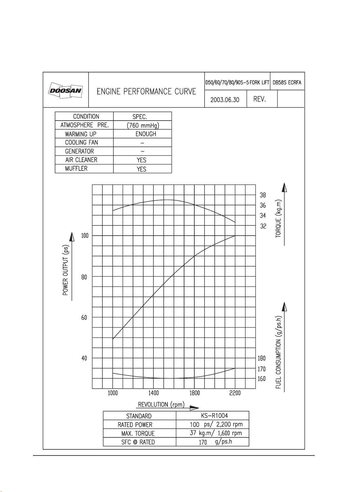
1. 2. Performance curve
1. 2.1. Performance curve (ECRFA), D50/60/70/80/90S-5 (3 speed)
General information - 2 -
Page 11

1. 2.2. Performance curve (ECRFD), D35/40/45S-5, D50/55C-5
General information - 3 -
Page 12
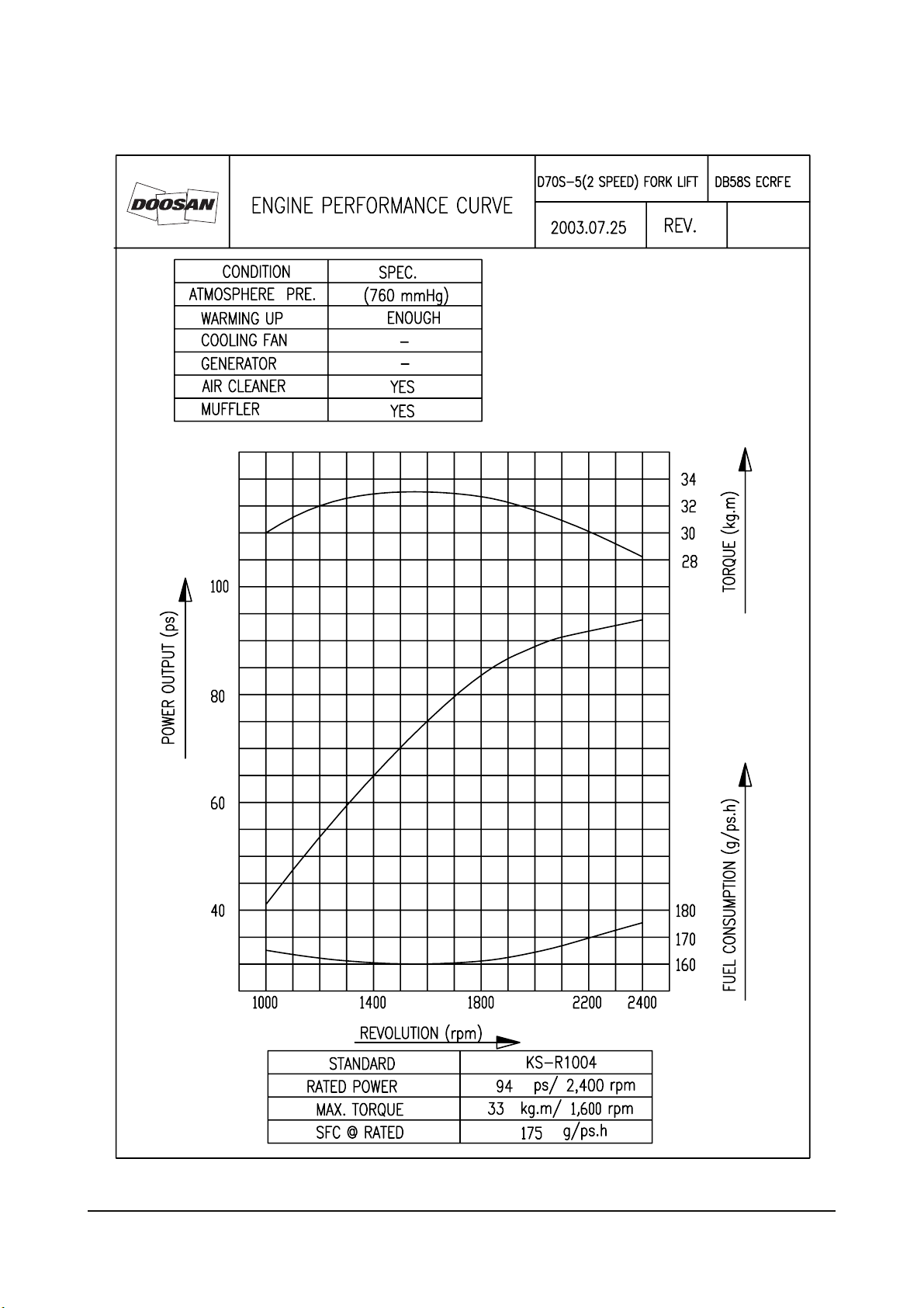
1. 2.3. Performance curve (ECRFE), D50/60/70S-5 (2 speed)
General information - 4 -
Page 13
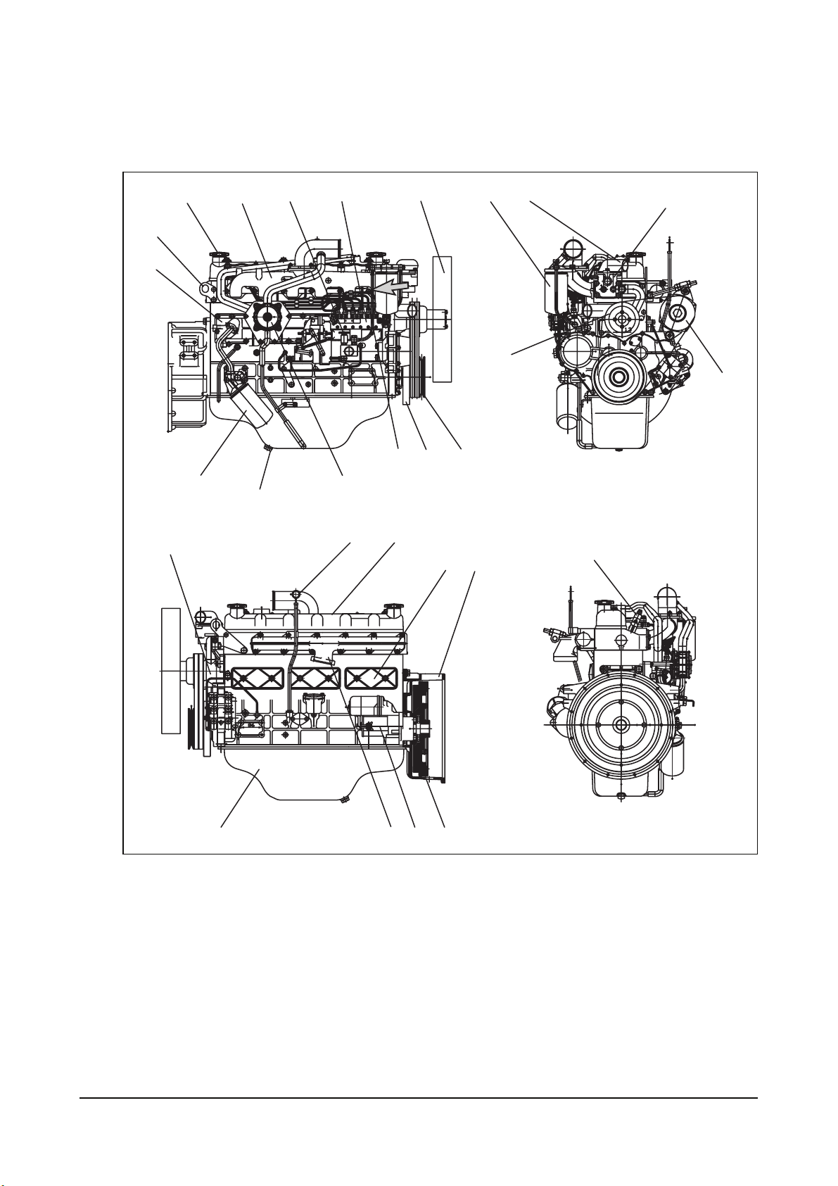
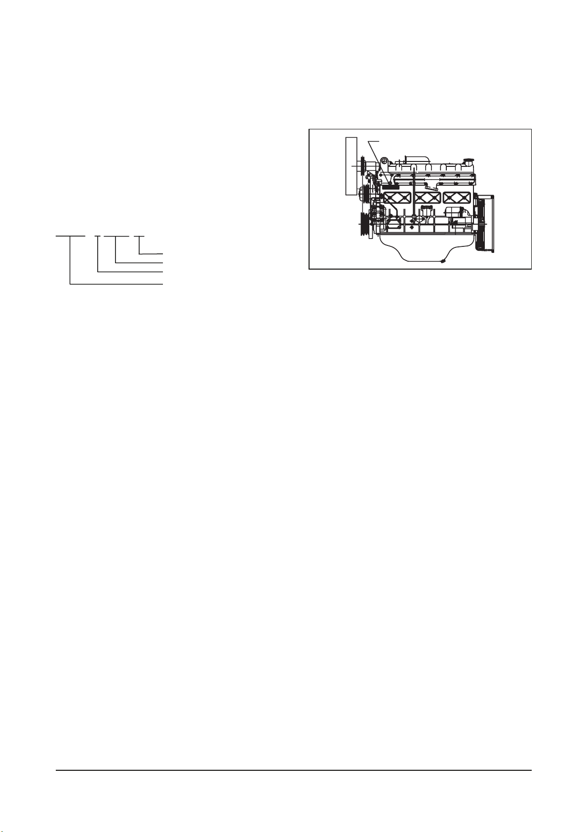
1.3. Engine assembly
1.3.1. Engine assembly view (ECRFA), D50/60/70/80/90S-5 (3 speed)
10
4
5
2
3
1
14
15
24
1 Oil filter 11 C.C.V 21 Push rod chamber cover
2 Lifting hook 12 Crank shaft pulley 22 Flywheel housing
3 Oil cooler 13 Vibration damper 23 Fly wheel
4 Intake manifold 14 Oil drain plug 24 Oil pan
5 Priming pump 15 water pump 25 Starter
6 Fuel injection pump 16 Alternator 26 Cylinder head cover
7 Fuel injection pipe 17 Oil level gauge 27 Fuel injection nozzle
8 Water outlet 18 Exhaust manifold 28 Fuel filter
9 Cooling fan 19 Water pump pulley
10 Oil filler cap 20 Thermostat housing
6
11
17 26
18
12
22
28
8
19
9
13
7
21
23
25
20
16
27
General information - 5 -
Page 14
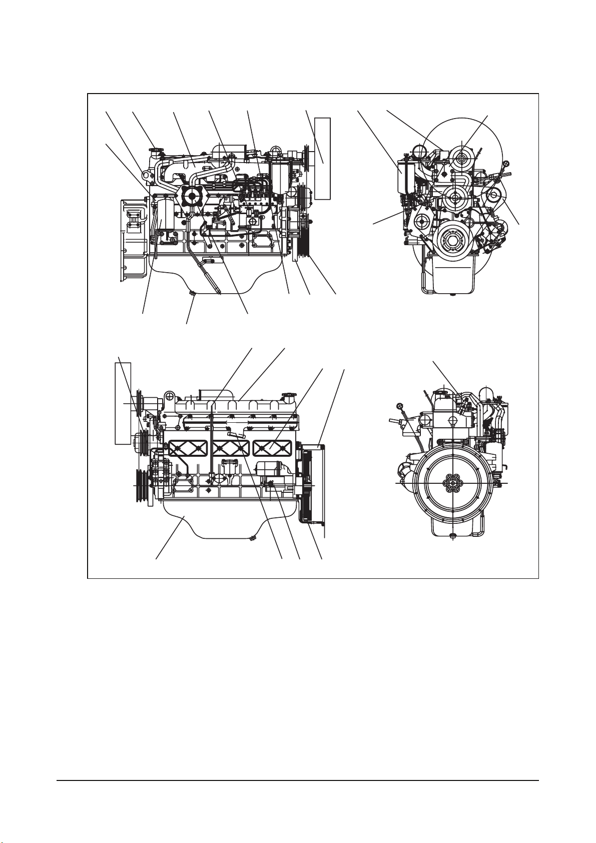
1.3.2. Engine assembly view (ECRFD), D35/40/45S-5, D50/55C-5
10
2
4
5
6
9
28
8
3
19
1
14
15
11
17 26
7
13
21
12
22
24
18
1 Oil filter 11 C.C.V 21 Push rod chamber cover
2 Lifting hook 12 Crank shaft pulley 22 Flywheel housing
3 Oil cooler 13 Vibration damper 23 Fly wheel
4 Intake manifold 14 Oil drain plug 24 Oil pan
5 Priming pump 15 water pump 25 Starter
6 Fuel injection pump 16 Alternator 26 Cylinder head cover
7 Fuel injection pipe 17 Oil level gauge 27 Fuel injection nozzle
8 Water outlet 18 Exhaust manifold 28 Fuel filter
9 Cooling fan 19 Water pump pulley
10 Oil filler cap 20 Thermostat housing
25
23
20
16
27
General information - 6 -
Page 15
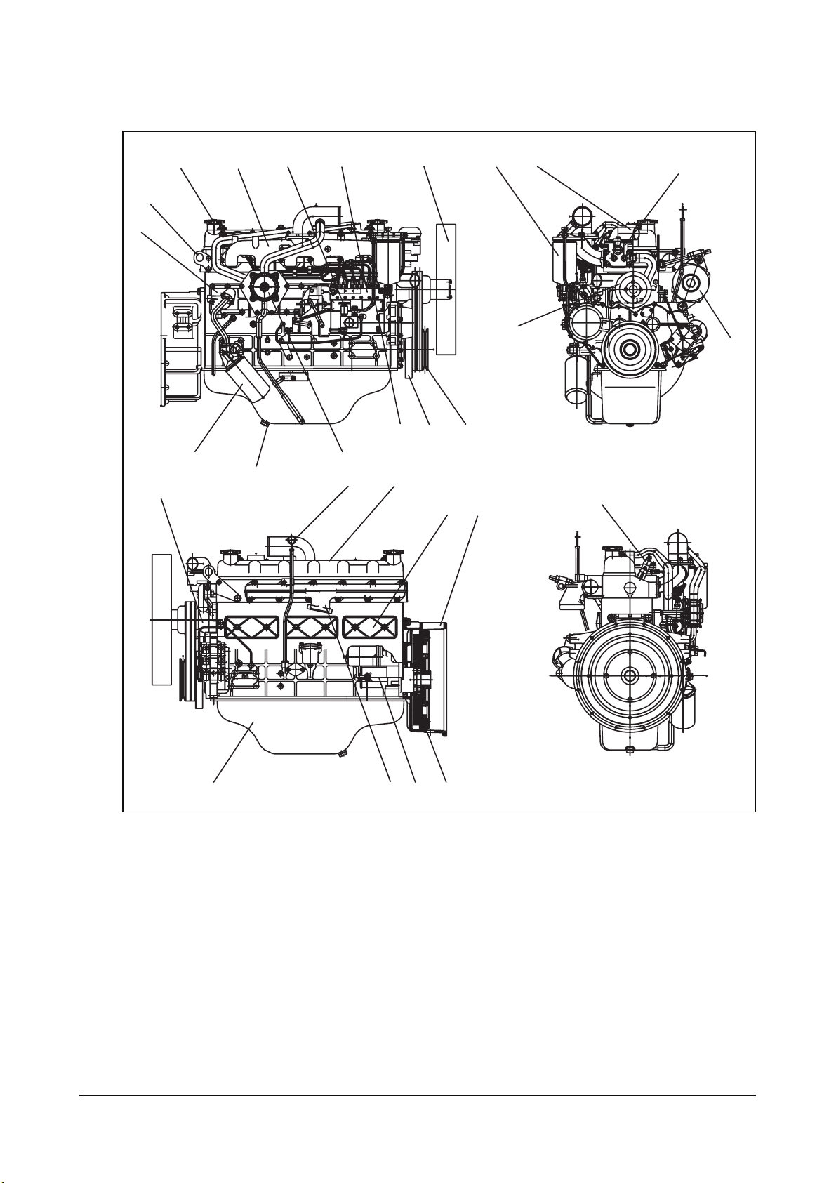
1.3.3. Engine assembly views (ECRFE), D50/60/70S-5 (2 speed)
10
4
5
6
9
28
8
2
3
19
15
1
14
11
17
7
26
13
21
12
22
24
18
25
23
1 Oil filter 11 C.C.V 21 Push rod chamber cover
2 Lifting hook 12 Crank shaft pulley 22 Flywheel housing
3 Oil cooler 13 Vibration damper 23 Fly wheel
4 Intake manifold 14 Oil drain plug 24 Oil pan
5 Priming pump 15 water pump 25 Starter
6 Fuel injection pump 16 Alternator 26 Cylinder head cover
7 Fuel injection pipe 17 Oil level gauge 27 Fuel injection nozzle
8 Water outlet 18 Exhaust manifold 28 Fuel filter
9 Cooling fan 19 Water pump pulley
10 Oil filler cap 20 Thermostat housing
20
16
27
General information - 7 -
Page 16
1.4. Safety regulations
1.4.1. General notes
Day-to-day use of power engines and the service products necessary for running them presents no
problems if the persons occupied with their operation, maintenance and care are given suitable training
and think as they work.
This summary is a compilation of the most important regulations. These are broken down into main
sections which contain the information necessary for preventing injury to persons, damage to property and
pollution. In addition to these regulations those dictated by the type of engine and its site are to be
observed also.
IMPORTANT.
If, despite all precautions, an accident occurs, in particular through contact with caustic acids, fuel
penetrating the skin, scalding from oil, antifreeze being splashed in the eyes etc., consult a doctor
immediately.
1.4.2. Regulations designed to prevent accidents
a) During commissioning, starting and operation
Before putting the engine into operation for the first time, read the operating instructions carefully and
familiarize yourself with the "critical" points. If you are unsure, ask your DOOSAN representative.
z For reasons of safety we recommend you attach a notice to the door of the engine room prohibiting
the access of unauthorized persons and that you draw the attention of the operating personal to
the fact that they are responsible for the safety of persons who enter the engine room.
z The engine must be started and operated only by authorized personnel. Ensure that the engine
cannot be started by unauthorized persons.
z When the engine is running, do not get too close to the rotating parts. Wear close-fitting clothing.
z Do not touch the engine with bare hands when it is warm from operation risk of burns.
z Exhaust gases are toxic. Comply with the installation instructions for the installation of DOOSAN
diesel engines which are to be operated in enclosed spaces. Ensure that there is adequate
ventilation and air extraction.
z Keep vicinity of engine, ladders and stairways free of oil and grease.
Accidents caused by slipping can have serious consequences.
b) During maintenance and care
z Always carry out maintenance work when the engine is switched off. If the engine has to be
maintained while it is running, e.g. changing the elements of change-over filters, remember that
there is a risk of scalding. Do not get too close to rotating parts.
z Change the oil when the engine is warm from operation.
CAUTION
There is a risk of burns and scalding. Do not touch oil drain valve or oil filters with bare hands.
Safety regulations - 8 -
Page 17
z Take into account the amount of oil in the sump. Use a vessel of sufficient size to ensure that the
oil will not overflow.
z Open the coolant circuit only when the engine has cooled down. If opening while the engine is still
warm is unavoidable, comply with the instructions In the chapter entitled "Cooling".
z Neither tighten up nor open pipes and hoses (lube oil circuit, coolant circuit and any additional
hydraulic oil circuit) during the operation. The fluid which flow out can cause injury.
z Fuel is inflammable. Do not smoke or use naked lights in its vicinity. The tank must be filled only
when the engine is switched off.
z Keep service products (anti-freeze) only in containers which can not be confused with drinks
containers.
z Comply with the manufacturer's instructions when handling batteries.
CAUTION
Accumulator acid is toxic and caustic. Battery gases are explosive.
c) When carrying out checking, setting and repair work
z Checking, setting and repair work must be carried out by authorized personnel only.
z Use only tools which are in satisfactory condition. Slip caused by the worn open-end wrench could
lead to Injury.
z When the engine is hanging on a crane, no-one must be allowed to stand or pass under it. Keep
lifting gear in good condition.
z When checking injectors, do not put your hands under the jet of fuel.
z Do not inhale at atomized fuel.
z When working on the electrical system disconnect the battery earth cable first. Connect it up again
last in prevent short circuits.
1.4.3. Regulations designed to prevent damage to engine and premature wear
(1) Never demand more of the engine than it was designed to yield for its intended purpose.
Detailed information on this can be found in the sales literature. The injection pump must not be
adjusted without prior written permission of DOOSAN.
(2) If faults occur, find the cause immediately and have it eliminate in order to prevent more serious of
damage.
(3) Use only genuine DOOSAN spare parts. DOOSAN will accept no responsibility for damage resulting
from the installation of other parts which are supposedly "just as good".
(4) In addition to the above, note the following points.
z Never let the engine run when dry, i.e. without lube oil or coolant. Use only DOOSAN-approved
service products. (engine oil, anti-freeze and anticorrosion agent)
z Pay attention to cleanliness. The Diesel fuel must be free of water. See "Maintenance and care".
z Have the engine maintained at the specified intervals.
z Do not switch off the engine immediately when it is warm, but let it run without load for about 5
minutes so that temperature equalization can take place.
z Never put cold coolant into an overheated engine. See "Maintenance and care".
Safety regulations - 9 -
Page 18
z Do not add so much engine oil that the oil level rises above the max. marking on the dipstick. Do
not exceed the maximum permissible tilt of the engine. Serious damage to the engine may result if
these instructions are not adhered to.
z Always ensure that the testing and monitoring equipment (for battery charge, oil pressure, and
coolant temperature) function satisfactorily.
z Comply with instructions for operation of the alternator. See "Commissioning and operation".
z Do not let the water pump run dry. If there is a risk of frost, drain the water when the engine
switched off.
1.4.4. Regulations designed to prevent pollution
a) Engine oil, filter element, fuel filter
z Take old oil only to an oil collection point. Take strict precautions to ensure that oil does not get into
the drains or into the ground.
z The drinking water supply may be contaminated.
z Oil and fuel filter elements are classed as dangerous waste and must be treated as such.
b) Coolant
z Treat undiluted anti-corrosion agent and / or antifreeze as dangerous waste.
z When disposing of spent coolant comply with the regulations of the relevant local authorities.
1.4.5. Notes on safety in handling used engine oil
Prolonged or repeated contact between the skin and any kind of engine oil decreases the skin.
Drying, irritation or inflammation of the skin may therefore occur. Used engine oil also contains dangerous
substances which have caused skin cancer in animal experiments. If the basic rules of hygiene and health
and safety at work are observed, health risks are not to the expected as a result of handling used engine oil.
<Health precautions>
z Avoid prolonged or repeated skin contact with used engine oil.
z Protect your skin by means of suitable agents (creams etc.) or wear protective gloves.
z Clean skin which has been in contact with engine oil.
z Wash thoroughly with soap and water, A nailbrush is an effective aid.
z Certain products make it easier to clean your hands.
z Do not use petrol, Diesel fuel, gas oil, thinners or solvents as washing agents.
z After washing apply a fatty skin cream to the skin.
z Change oil-soaked clothing and shoes.
z Do not put oily rags into your pockets.
Ensure that used engine oil is disposed of properly.
- Engine oil can endanger the water supply -
For this reason do not let engine oil get into the ground, waterways, the drains or the sewers. Violations
are punishable. Collect and dispose of used engine oil carefully.
For information on collection points please contact the seller, the supplier or the local authorities.
Safety regulations - 10 -
Page 19

1.4.5. General repair instructions
1. Before performing service operation, disconnect the grounding cable from the battery for reducing the
chance of cable damage and burning due to short-circuiting.
2. Use covers for preventing the components from damage or pollution.
3. Engine oil and anti-freeze solution must be handled with reasonable care as they cause paint damage.
4. The use of proper tools and special tools where specified is important to efficient and reliable service
operation.
5. Use genuine DOOSAN parts necessarily.
6. Used cotter pins, gaskets, O-rings, oil seals, lock washer and self-lock nuts should be discarded and
new ones should be prepared for installation as normal function of the parts can not be maintained if
these parts are reused.
7. To facilitate proper and smooth reassemble operation, keep disassembled parts neatly in groups.
Keeping fixing bolts and nut separately is very important as they vary in hardness and design depending
on position of installation.
8. Clean the parts before inspection or reassembly. Also clean oil ports, etc. using compressed air to make
certain they are free from restrictions.
9. Lubricate rotating and sliding faces of parts with oil or grease before installation.
10. When necessary, use sealer on gaskets to prevent leakage.
11. Carefully observe all torque specifications for bolts and nuts.
12. When service operation is completed, make a final check to be sure service has been done properly.
Safety regulations - 11 -
Page 20
2. TECHNICAL INFORMATION
2.1. Engine model and serial number
The engine model and serial number is located on the
engine as illustrated. These numbers are required
when requesting warranty and ordering parts. They
are also referred to as engine model and serial
number because of their location.
Engine serial No. (example : DB58)
DB58S 3 00001 FA
Engine suffix (ECRFA)
Serial no.
Production year (2003)
Engine model
ENGINE SERIAL NO.
EC90M011
Technical information - 12 -
Page 21
2.2. Engine type
The Engines DB58S are in-line vertical, water-cooled, 6-cylinder four stroke diesel engines with direct
injection. DB58S is natural aspiration.
2.2.1. Cylinder block
The cylinder block is a single piece of alloy cast iron. To increase its stiffness, it is extended to a level
below the crankshaft center line. The engine has replaceable dry cylinder liners and common cylinder
heads with struck-in valve seat rings and replaceable valve guides,
2.2.2. Piston con-rod / crankshaft
The forged crankshaft is a integrate type (Counterweight is integrated with crank shaft body). Radial oil
seal on crankshaft and flywheel are provided to seal the flywheel housing inside penetrations.
The con-rods (connecting rods) are die-forged and can be removed through the top of the cylinders
together with the pistons. Crankshaft and connecting rods run in steel-backed lead bronze ready-to fit type
bearings.
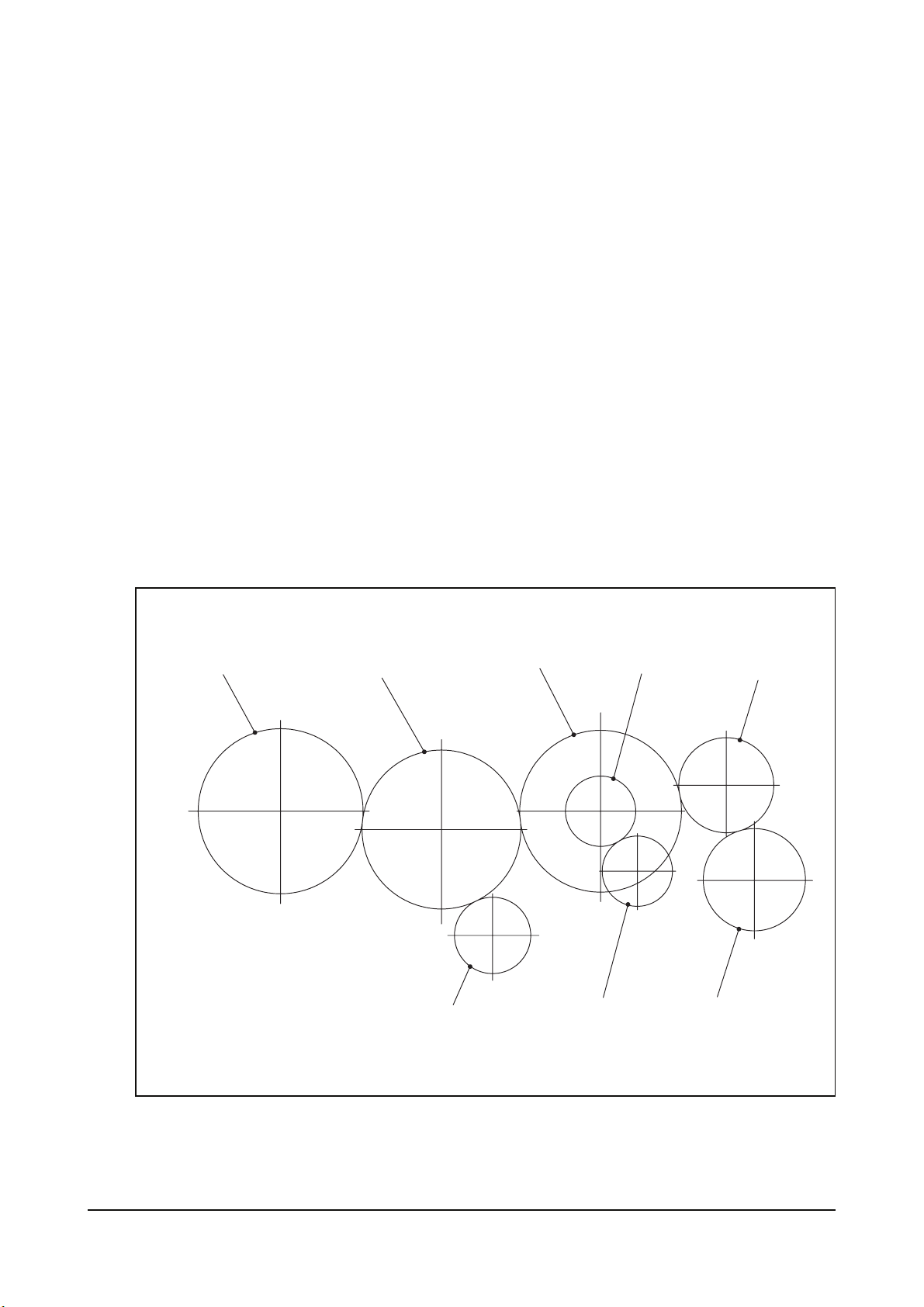
2.3. Engine timing
Camshaft, oil pump, PTO (power take off) pump and injection pump are driven by a gear train arranged at
the front end.
Injection pump gear
(Z = 50)
Idle gear
(Z = 51)
Camshaft gear
(Z = 50)
Oil pump drive gear
(Z = 12)
P.T.O Drive gear
(Z=24)
Crankshaft gear
(Z = 25)
Oil pump gear
(Z = 9)
P.T.O gear (Option)
(Z = 25)
EC90M013
Technical information - 13 -
Page 22
2.4. Valves
The overhead valves are actuated via chilled cast iron tappets, push rods and rocker arms from the
camshaft.
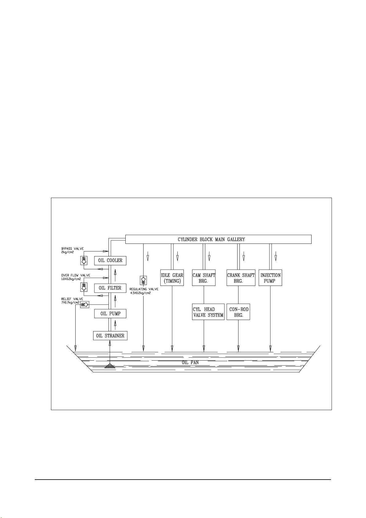
2.5. Lubrication system
The engine is equipped with force-feed lubrication.
The pressure is produced by a gear pump whose drive gear is in direct mesh with the camshaft gear at the
middle of cylinder block.
The oil pump draws the oil from the oil sump and delivers it through the oil cooler and oil filter to the main
distributor gallery and from there to the main bearings, big-end bearings and camshaft bearings as well as
to the small-end bearings and the rocker arms.
The injection pump are also connected to the engine lubricating system.
The cylinder block walls and timing gears are splash-lubricated.
The lube oil is cleaned in a full-flow oil filter.
EC90M014
Technical information - 14 -
Page 23
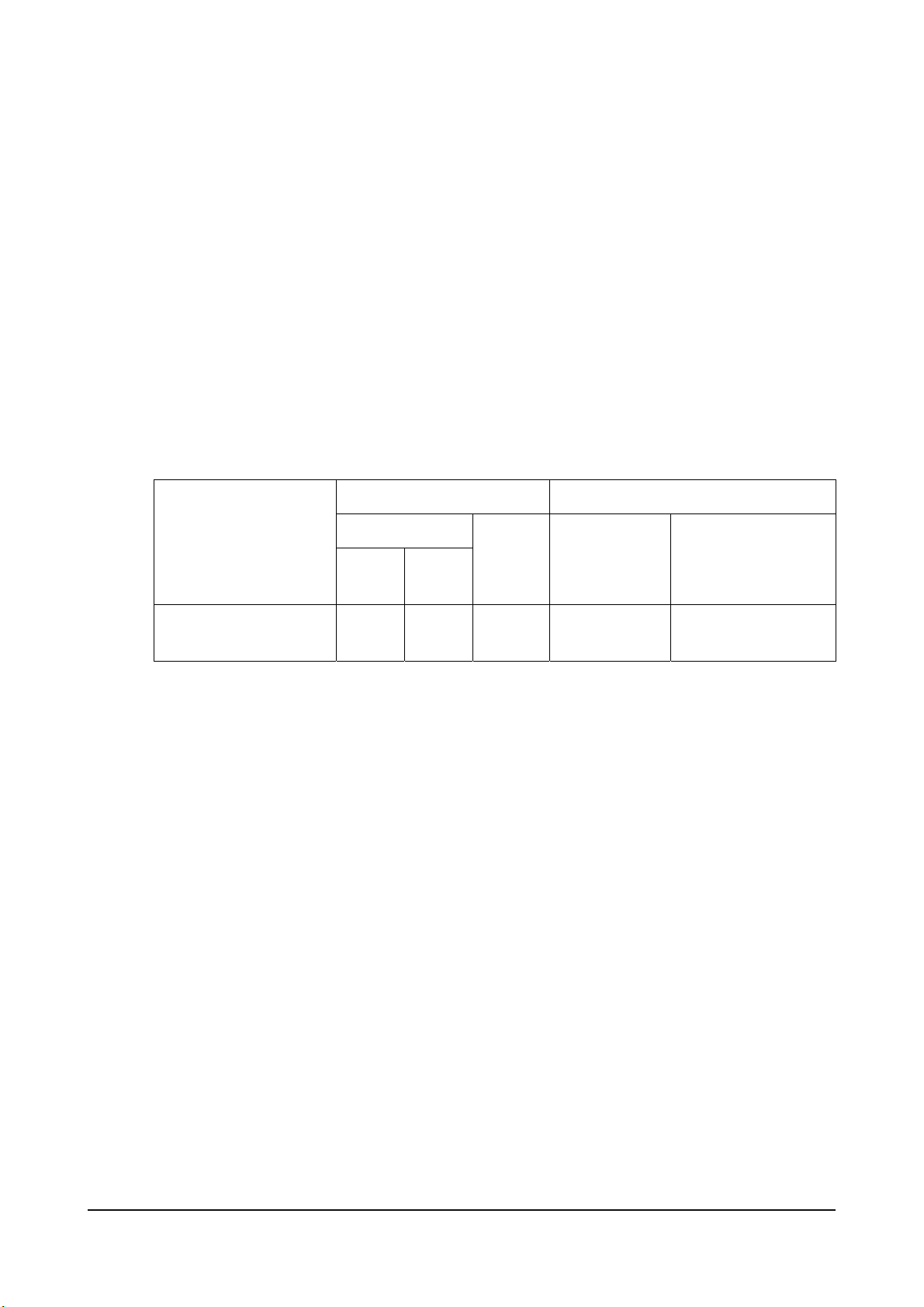
2.5.1. Recommend of lubricating oil
Initial factory fill is high quality break-in oil for API Service. During the break-in period (50 hours),
frequently check the oil level. Somewhat higher oil consumption is normal until piston rings are seated.
The oil level should be maintained in the safe range between the Min. and Max. marks on the dipstick. The
safe range between the marks represents approximately 3 liters. To obtain the best engine performance
and engine life, grade of engine oil is recommended. Engine oils are specified by API Service, letter
designations and SAE viscosity numbers. If the specified motor oil is not available, use a reputable brand
of engine oil labeled for API Service CH-4 and SAE viscosity 30 or 15W40. Refer to oil identification
symbol on the container.
z Engine oil should be changed at the specified intervals.
Oil filter cartridge should be changed simultaneously.
- First oil change : 50 hr operating
- After 50hr operation ; 250
z The following oils are also recommended
Engine oil capacity Recommend oil
Max.
(liter)
Oil pan
(liter)
Min.
Total
(liter)
SAE No. API No.
SAE10W40
SAE15W40
ACEA-E2 or ACEA-E3
(API CH-4)
Engine model
DB58S 19 14 20.5
Technical information - 15 -
Page 24
* If long oil change intervals are to be used, ACEA-E3 oil must be used.
2.5.2. Oil cooler
An oil cooler is provided between the oil filter and the cylinder block. This cooler is a flat tube type with
turbulence inserts and operated by the coolant.
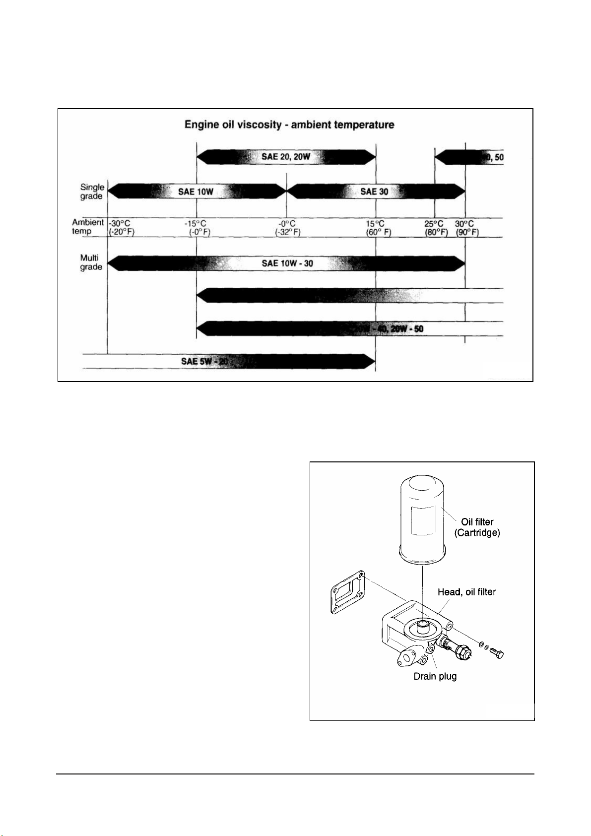
2.5.3. Oil filter
• Check for oil pressure and oil leaks, and
repair or replace the oil filter if necessary.
• Change the oil filter cartridge
simultaneously at every replacement of
engine oil.
EA4M1008
Technical information - 16 -
EDM3001I
<ECRFD>
Page 25
Cartridge,
Oil filter
<ECRFA, ECRFE>
Head, oil filter
2.6. Air cleaner
In case that elements are deformed, damaged
or if the air cleaner has a crack, replace it.
By the definite interval, the elements must be
cleaned and replaced.
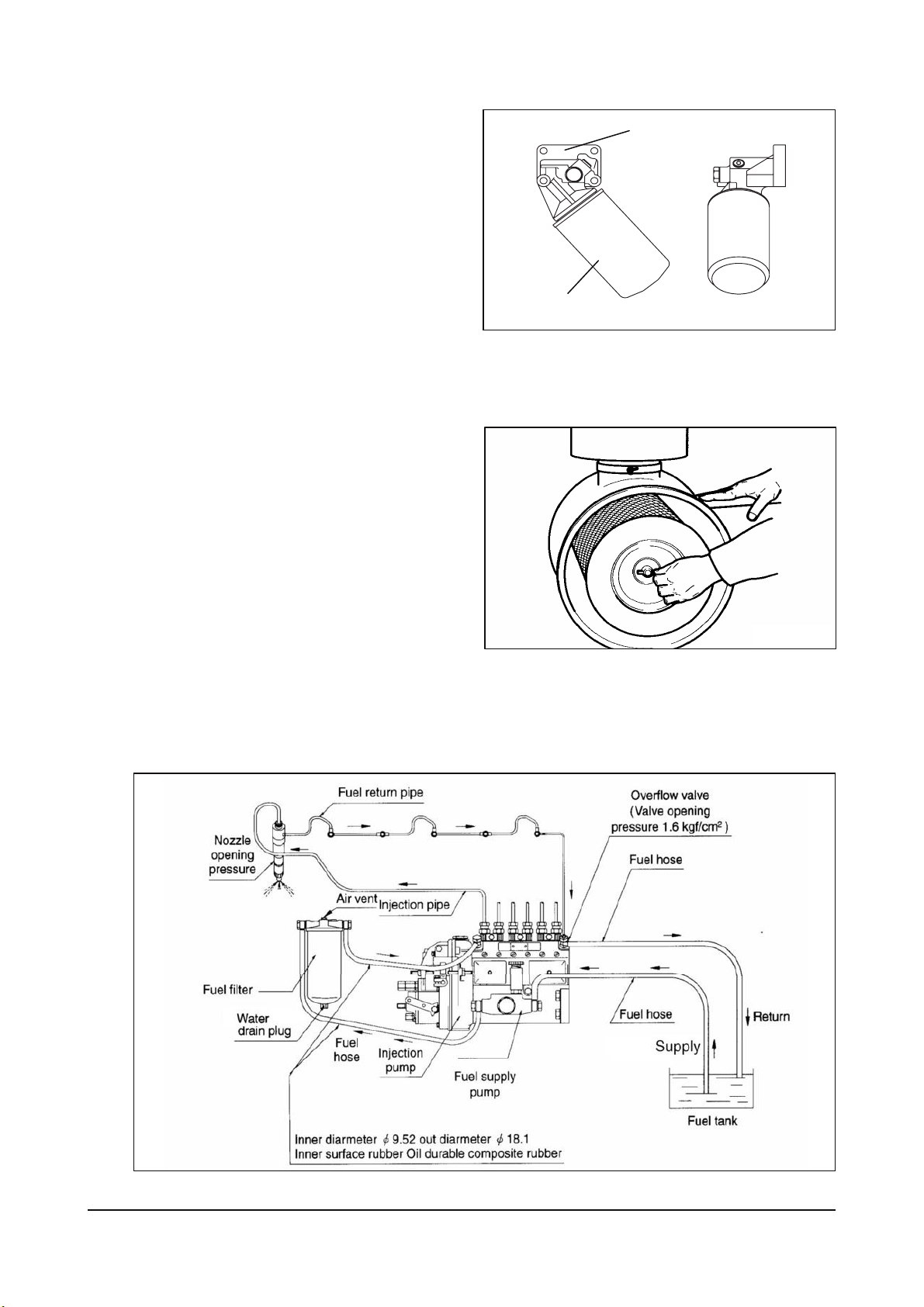
2.7. Fuel system
The fuel is delivered by the fuel feed pump via the fuel filter to the injection pump and from there to the
injection nozzles.
EC9OM015
EFM1002I
EC9OM065
Technical information - 17 -
Page 26
The fuel is sprayed into the cylinders through nozzles fitted in screw-fit injection nozzle holders in the
cylinder heads.
Excessively delivered fuel and leak fuel from the nozzle flow through the return pipe back to the tank.
A strainer is arranged ahead of the fuel feed pump.
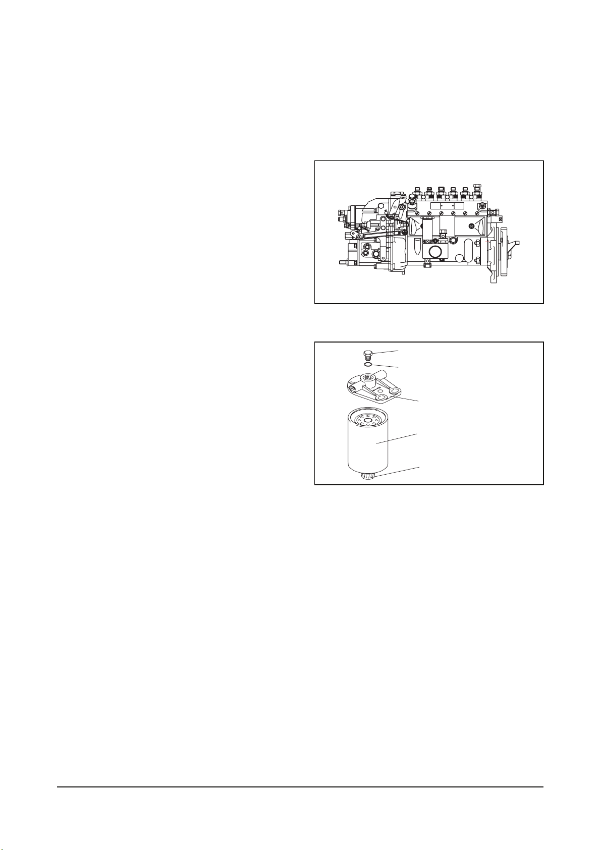
2.7.1. Injection pump
The in-line injection pump is driven via gears
from the crankshaft. It is connected to the
force feed lubricating system of the engine
and consequently maintenance-free. The
governor flange-mounted on the pump casing
is a variable range governor designed to
keep the speed set of varying load.
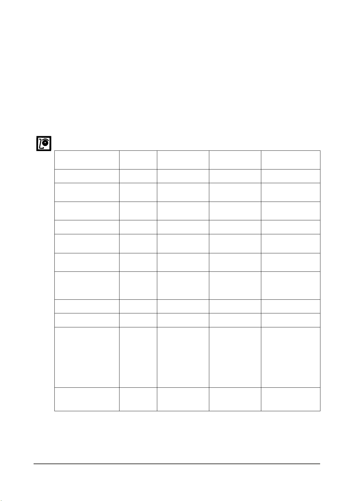
2.7.2. Fuel filter
This fuel filter has two functions not only oil
filtering but
also water separating
Before entering the suction chamber of the
injection pump, the fuel is cleaned in a
strainer of fuel feed pump and a fuel filter.
Drain water in filter with loosening the drain
plug under filter manually from time to time.
The fuel filter element should be replaced at
every 200 hours.
Air bleeding plug
Seal ring
Head, fuel filter
Cartridge, fuel filter
Water drain plug
2.7.3. Fuel requirements
DOOSAN diesel engines was designed to use Number 2-D diesel fuel or equivalent that meets
specification DIN 51601-DK. For maximum fuel economy, Number 2-D fuel whenever possible. When
temperatures are below -7 °C (20 °F), use Number 1-D fuel. If Number 1-D fuel is not available, the
mixture of one kerosene to two gallons of Number 2-D fuel can be used. Once kerosene has been added,
the engine should be run for several minutes to mix the fuel.
EC9OM016
EC9OM017
Technical information - 18 -
Page 27
2.7.4. How to select fuel oil
Fuel quality is an important factor in obtaining satisfactory engine performance, long engine life, and
acceptable exhaust emission levels. DOOSAN engines are designed to operate on most diesel fuels
marketed today. In general, fuels meeting the properties of ASTM Designation D975 (grades 1-D and 2-D)
have provided satisfactory performance.
The ASTM 975 specification, however, does not in itself adequately define the fuel characteristics needed
for assurance of fuel quality.
The properties listed in the fuel oil selection chart below have provided optimum engine performance.
Grade 2-D fuel is normally available for generator service. Grade 1-D fuel should not be used in pleasure
craft engines, except in an emergency.
Fuel Oil Selection Chart
General Fuel
Classification
Gravity, °API #) D 287 40 ~ 44 33 ~ 37 0.815 ~ 0.855
ASTM
Test
No. 1
ASTM 1-D
No. 2
ASTM 2-D
DIN 51601
Flash Point
Min. °F (°C)
Viscosity, Kinematic
CST 100 °F (40 °C )
Cloud Point °F #) D 2500 See Note 1) See Note 1) See Note 1)
Sulfur Content
wt%, Max.
Carbon Residue
on 10%, wt%, Max.
Accelerated Stability
Total Insolubles
mg/100 ml, Max. #)
Ash, wt%, Max. D 482 0.01 0.01
Cetane Number, Min. +) D 613 45 45 > 45
Distillation
Temperature, ℉(℃)
IMP, Typican #)
10% Typical #)
50% Typical #)
90% +)
End Point #)
D 93 100 (38) 125 (52) 131 (55)
D 445 1.3 ~ 2.4 1.9 ~ 4.1 1.8 ~ 10
D 129 0.5 0.5 0.15
D 524 0.15 0.35 0.1
D 2274 1.5 1.5
D 86
350(177)
385(196)
45(218)
500 (260) Max.
550(288) Max.
625(329) Max.
675(357) Max.
375(191)
430(221)
510(256)
680(360)
Water & Sediment
%, Max.
#) Not specified In ASTM D 975
+) Differs from ASTM D 975
NOTE
1) The cloud point should be 6 °C (10 °F) below the lowest expected fuel temperature to prevent clogging
of fuel fitters by crystals.
D 1796 0.05 0.05 0.05
Technical information - 19 -
Page 28

2.8. Cooling system
The engine has a liquid-cooling system. The fresh water pump is a maintenance-free by V-belt from the
crankshaft pulley.
Depending on the agreed extent of delivery and the design of the engine, the coolant circuit can be
equipped with temperature monitors which, in the event of loss of coolant, shut the engine down.
z Check the coolant level of the expansion tank by removing the expansion tank filler cap, and add coolant
if necessary.
z When injecting antifreeze solution, first drain out the old coolant from the cylinder block and radiator, and
then clean them with cleaning solution.
z Be sure to mix soft water with antifreeze solution.
Technical information - 20 -
Page 29
2.8.1. Anti-freeze
The anti-freeze, 50% of the whole coolant, is always to be used to prevent the cooling system from the
corrosion. And in winter the amount of anti-freeze shown in the following table should be used in
accordance with the ambient temperature.
Temperature (°C)
Ambient
Cooling water (%) Anti-freeze (%)
Over -10
-10
-15
-20
-25
-30
-40
85
80
73
67
60
56
50
15
20
27
33
40
44
50
As the individual freezing points corresponding to the proportions of antifreeze in the table are subject to
change slightly according to the kind of antifreeze, you must follow the specifications provided by the
antifreeze manufacturer.
As the ratio of antifreeze in the mixture decrease each time new coolant is added to make up for the loss
coolant resulting from engine operation, Check the mix ratio with every replenishment of coolant, and top
up as necessary.
2.8.2. Cooling water
z Regarding the engine cooling water, the hard water must be used (Do not use the soft water).
z The engine cooling water can be used diluting it with antifreezing solution 40% and the additive for rust
prevention (DCA4) 3 ∼ 5 %.
z The density of above solution and additive must be inspected every 500 hours to maintain it properly.
NOTE
The proper density control of antifreezing solution and rust preventing additive will be able to
prevent the rusting effectively and maintain the stable quality of engine.
For the improper control might give the fatal damage to the cooling water pump and cylinder liners,
detail care is needed.
z Since DB58 cylinder liner is dry type, particularly the cooling water control should be applied thoroughly.
z The density of antifreezing solution and additive for rust prevention is able to be confirmed by the
cooling water test kit. (Fleetguard CC2602M)
z How to use the cooling water test kit
(1) When the cooling water temp. of engine is in the range of 10 ∼ 55 °C, loosen the plug for cooling
water discharge and fill the plastic cup about a half.
Technical information - 21 -
Page 30

NOTE:
In taking the cooling water sample, if the water in auxiliary tank were taken, it is hard to measure
the accurate density. Take the cooling water sample necessarily loosening the cooling water
discharge plug.
(2) At the state of a test paper soaked in the sampled water, after taking the paper out through water
agitation, shake off the water.
(3) Wait for about 45 sec. till the color change of test paper.
NOTE:
However, it should not elapse longer than 75 sec, and if it did, the hue would change.
(4) Make the numerical value by comparing the test paper which hue has changed with the color list of
label on storage bottle.
(5) By comparing the hue changed into yellowish green or so with the green color indication of test paper
storage bottle, confirm the density. (Then, the density indication must be in the hue range of 33% to
50%).
(6) The brown at the middle of test paper and the lower pink color indication represent the additive state
for rust prevention, and the proper range is that the meeting numerical value of brown (vertical) and
pink color (horizontal) (7) locates in the range of 0.3 to 0.8 at the color list of label on the test paper
storage bottle.
(8) In case of less than 0.3, replenish the additive for rust prevention (DCA4), and in case of more than
0.8, pour out the cooling water about 50% and then readjust the density after refilling with clean fresh
water.
Technical information - 22 -
Page 31

2.9. V-belt tension check and adjust
z V-Belt
By the finger-pressure the belt is pressed by
10mm ∼ 15mm between the fan pulley and
the alternator pulley in normal condition. For
the adjustment of the tension, loosen the
adjusting bolts which support the alternator,
adjust the tension and tighten the bolts
again.
z Poly belt
Poly belt will be properly tensioned if the
deflection force “F” is applied midway
between the belt`s tangent points with the
pulley.
T = 0.015 x S (about 1.5mm per 100mm)
EA9O2006
EB5O6003
Technical information - 23 -
Page 32

2.10. Valve clearance and
adjustment
NOTE:
The cylinder head bolts were previously
tightened with the torque wrench.
Therefore it is not necessary to retighten
the cylinder head bolts before adjusting
the valve clearance.
Rocker arm screw
lock nut torque
z After letting the #1 cylinder's piston come
at the compression top dead center by
turning the crankshaft, adjust the valve
clearances.
z Loosen the lock nuts of rocker arm
adjusting screws and push the feeler
gauge of specified value between a rocker
arm and a valve stem and adjust the
clearance with adjusting screw
respectively and then tighten with the lock
nut.
z As for the valve clearance, adjust it when
in cold, as follows.
2.6 ±0.5kg.m
EAOO4014
EJM1035S
Model Intake Valve Exhaust Valve
DB58S 0.4 mm 0.4 mm
1) Rotate the crankshaft to overlap the intake and the exhaust valves of #6, then #1 cylinder become the
compression state of top dead center.
2) Therefore adjust the valve clearance corresponding to “ ” of lower figure. At this time there are
no force on the push rods of #1 cylinder.
3) Rotating the crankshaft by one revolution, #6 cylinder become the compression state of top dead center.
4) Thereafter adjust the valve clearances corresponding to “ ” of lower figure.
5) After reinsuring the valve clearances, retighten if necessary.
Technical information - 24 -
Page 33

• No. 1 cylinder is located at the side where flywheel was installed.
Cooling fan Cylinder no.
2.11. Cylinder compression
pressure
z Stop the engine after warming up, and
take out preheating plug and injection pipe.
z Install the special tool (compression gauge
adapter) at the preheating plug hole, and
connect the compression pressure gauge
there.
z Check the compression pressure at gauge
several times until highest compression
reading is reached.
Standard value 28kg/cm² over
Limit value 24kg/cm²
Difference
between each
cylinder
z Condition : Water temperature 75°C.
Within ± 10 %
Exhaust valve Intake valve Fly wheel
EC9OM020
EJM1046S
EJM1047I
Technical information - 25 -
Page 34

2.12. Injection nozzle
z Install a nozzle on the nozzle tester.
z If the inspected injection pressure is less than the specified value, adjust using the adjusting shims.
Engine model Injection nozzle pressure
DB58S 220 kg/cm²
z Check the atomizing state and replace it if abnormal.
2.13. Battery
z Inspect for any leakage of electrolytic solution owing to battery crack, and replace the battery in case of
poor condition.
z Inspect for amount of electrolytic solution, and replenish if insufficient.
z Measure the gravity of electrolytic solution, if less than specified value (1.12 ∼ 1.28), replenish.
2.14. Starting motor
z In case of engine maintenance, clean pinion and ring gear thoroughly putting in the fuel, and coat them
with grease.
Also, in case of washing engine room and so forth, inspect the wiring state being careful for water not to
get in.
EFM1006I
EFM1007I
Technical information - 26 -
Page 35

2.15. Diagnosis and remedy
r
z The following description summarizes the probable cause of and remedy for general failure by item.
z Immediate countermeasures should be taken before a failure is inflamed if any symptom is detected.
1. Engine Starting Impossible
Starting motor does not turn
Inspection of battery electrolytic
Iiquid amount & gravity
Normal Too Iow
Adjustment,
Recharging
Inspection of Ioose electric
Wiring & short
Normal
Inspection of starter switch
Inspection of starter relay
Normal Replace
Inspection of starter switch
Normal
Starting motor
disassembly
Retighten.
Replace
Retighten.
Replace
Retighten.
Replace
Starting motor turns but
engine does not revolution
Engine
Inspect air cleaner
Normal Polluted
Replace or
Clean element
Check compression
pressure
Normal Too low
Repai
Replace
Inspect of
other parts
Check valve
clearance
Normal
Check
clinder
head gasket
Normal
Adjust
Replace
Fule
Inspect amount of fule
Normal No fule
Replenish
Inspect fule injection
Normal No fule injection
Inspect
injection
timing
Normal
Inspect injust
nozzle (injection
pressure, injection
state ect.)
Normal
Disassemble and
Inspect injection pump
Air bleeding
and re-start
Adiust
Repair
Replace
Engine disassembly
(valve assembly, piston,
cylinder liner ect.
Inspect fule feed pump for function
Normal
Disassemble and
Inspect injection pump
Inspect feed pump valne and
Normal
Inspect fule filter
Dirty element ald/or
overflow valve faulty
Replace
Clean
Replace
Air mixture in fule
Retighten connection
Parts. Replace gasket
Air bleeding
Continuous entry of air
In fuel system
Disassemble and
Check fuel feed pump
Technical information - 27 -
Page 36

2. Engine Overheated
Operating state
1. Overload
2. Radiator core clogged
Cooling system
Fule system
3. Continuous over-run
Check coolant level
Normal Too low
Check fan belt
tension, wear
or damage etc.
Normal
Repair.
Replenish
Replace
Check fresh
radiator tank cap
Normal Repair
Check thermostat
Normal Repair
Inspect radiator Damage
Inspect fule quality
Poor
Clean and replace
with specified fule
Inspect cooling
water leakage
Extemal
Repair
Replace
Intemal
Engine
disassembly
Fuel excessive supply
Check injection nozzle
Normal Abnormal
Adjust or
repair
Repair
Replace
Injection
pump
Normal
Check cooling
water passage
Repair.
Replace
Check cooling
water pump
Normal
Repair.
Replace
Engine
disassembly
Technical information - 28 -
Page 37

3. Output insufficient
Engine Chassis
Check for clutch silp
Check for air maxing
In fule
Inspect fule supply pump
Normal
Clean.
Replace
Inspect fule filter
and over flow valve
Normal Replace
Inspect injection pipes
Normal
Repair
Replace
Inspect injection nozzle
(injection pressure,
atomizing state ect.)
Normal
Adjust.
Replace
Others Fule system
Inspect air cleaner
Normal
Clean.
Replace
Inspect engine control
rod, link, cable, ect
Normal
Repair
Replace
Check valve clearance
Normal Adjust
Inspect cylinser head
gasket for damage
Normal
Replace
Engine disassembly
(valve assembly)
Adjust or replace clutch
Inspect air leakage
of air piping line
Normal
Retighten.
Replace
Inspect air leakage
of intercooler
Check injection timing
Normal Adjust.
Disassemble engine
or injection pump
Check turbocharger
Normal
Repair
Replace
Disassemble injection
pump or engine
Technical information - 29 -
Page 38

4. Oil Pressure Iowered
Check oil amount
Check if pressure
gauge indicates wrongly
Normal
Check cooling
temperature
Normal
Inspect oil quality
Normal
Check oil
relief valve
Normal
Refer to engine overheat
Reyighten.
Replace
Too high
Disassemble engine
or injection pump
Water and fule
mixed in oil
To Iow
Use recommened oil
(replenish)
Improper
Replace with
recommended oil
Disassemble
engine
Technical information - 30 -
Page 39

5. Fule Consumption Excessive
Cause according to use conditions
1. Overlow
2. Frequent use of low gear position
3. Frequent use of high gear position
Inspect fule Ieakage
at low speed
4. Clutch slip
5. Too low tire inflation pressure
Normal Fule leakage
Inspect injection nozzle
(injection pressure
atomizing state, ect.)
Normal
Adjust
Replace
Inspect injection timing
Normal
Adjust
Inspect compressed
pressure
Normal
Adjust
Disassemble
injection pump
Check valve
clearance
Retighten
Replace
Pepair, Replace
(cylinder liner,
piston ring, piston)
Normal
Adjust
Inspect head gasket
Normal
Replace
Disassemble engine
(valve assembly, pistion,
cylinder er, ect.)
Technical information - 31 -
Page 40

6. Oil Consumption Excessive
Cause according to use conditions
1. Excessive oil infusing
2. Continuous operation in low speed
or extremely cold state
Inspect oil leakage
Normal Oil leakage
Check oil quality
Extermal Internal
Replace with
specified oil
Retighten.
Replace
7. Engine Knocking
Inspection combustion of fule & oil
(carbon residue of exhaust gas)
Check compressed
pressure
Engine disassembly
(piston, cylinder liner)
Inspect air cleaner
Clean Replace
Normal
Disassemble
cylinder head
(valve stem seal)
Unconfirmed Confirm
Inspect compressed
pressure
Normal Too Low
Inspect injection
timing
Normal Adjust
Check fule quality
Check valve clearance and
cylinder head gasket crush
Normal
Disassemble
engine
Use specified fule
Technical information - 32 -
Disassemble
engine
Replace
Adjust
Page 41

8. Battery Discharge
Battery Wiring, Switch Altemator
Check electrolytic
liquid amount
Normal
Electrolytic
liquid’s standard
Replenish
Inspect cut wire
shorts and loose
connections, etc.
Repair. Replace
Damaged
battery case
Replace Charging
Normal Abnormal
Check charged stated
Battery self
dischage
Check fan belt
tension & damage
Battery over
charging
Inspect altemator
and voltage regulator
Adjust
Replace
Discharging
Disassemble altemator
and voltage regulator
Technical information - 33 -
Page 42

Condition Causes Remedies
1) Starting difficult
(1) Compression pressure
2) Idle operation abnormal
3) Engine output insufficient
(1) Continuous output
z Valve's poor shut, stem distortion
z Valve spring damage
z Cylinder head gasket's leak
z Wear of piston, piston ring or liner
z Injection timing incorrect
z Air mixing at injection pump
z Valve clearance incorrect
Insufficient
(2) Output insufficient
z Valve tightness poor
z Cylinder head gasket's leak
z Wear, stick, damage of piston ring
z Injection timing incorrect
z Fuel injection amount insufficient
z Nozzle injection pressure improper or stuck
z Supply pump's function lowered
z Fuel pipe system clogged
z Air suction amount insufficient
z Turbocharger poor
z Compression pressure insufficient
when in acceleration
4) Overheating
z Injection timing incorrect
z Fuel injection amount insufficient
z Injection pump timer's function insufficient
z Nozzle injection pressure, injection angle
improper
z Supply pump's function lowered
z Air intake amount insufficient
z Engine oil insufficient or poor
z Cooling water insufficient
z Fan belt loosened, worn, damaged
z Cooling water pump's function lowered
z Water temperature regulator's operation poor
z Valve clearance incorrect
z Exhaust system's resistance increased
Repair or replace
Replace valve spring
Replace gasket
Adjust
Adjust
Remove air
Adjust
Repair
Replace gasket
Replace piston ring
Adjust
Adjust injection pump
Adjust or replace
Repair or replace
Repair
Clean or replace air cleaner
Repair or replace
Disassemble engine
Adjust
Adjust injection pump
Repair or replace
Repair, replace
Repair or replace
Clean or replace air cleaner
Replenish or replace
Replenish or replace
Adjust or replace
Repair or replace
Replace
Adjust
Clean or replace
Technical information - 34 -
Page 43

Condition Causes Remedies
5) Engine noisy For noises arise compositely such as
rotating parts, lapping parts etc., there is
necessity to search the cause of noises
accurately.
(1) Crankshaft
z As the wear of bearing or crankshaft
progress, the oil clearances increase.
z Lopsided wear of crankshaft
z Oil supply insufficient due to oil passage
clogging
(2) Connecting rod and
z Stuck bearing
z Lopsided wear of connecting rod bearing
Connecting rod bearing
z Lopsided wear of crank pin
z Connecting rod distortion
z Stuck bearing
z Oil supply insufficiency as clogging at oil
passage progresses
(3) Piston, piston pin &
piston ring
(4) Others
6) Fuel Consumption excessive
7) Oil consumption excessive
z Piston clearance increase as the wear of
piston and piston ring progresses
z Wear of piston or piston pin
z Piston stuck
z Piston insertion poor
z Piston ring damaged
z Wear of crankshaft, thrust bearing
z Camshaft end play increased
z Idle gear end play increased
z Timing gear backlash excessive
z Valve clearance excessive
z Abnormal wear of tappet, cam
z Injection timing incorrect
z Fuel injection amount excessive
excessive
(1) Oil level elevated
z Clearance between cylinder liner &
piston
z Wear of piston ring, ring groove
z Piston ring's damage, stick, wear
z Piston ring opening's disposition
improper
z Piston skirt part damaged or abnormal
wear
(2) Oil level lowered
(3) Oil leak
z Oil ring's oil return hole clogged
z Oil ring's contact poor
z Looseness of valve stem & guide
z Wear of valve stem seal
z Cylinder head gasket’s leak
z Looseness of connection parts
z Various parts' packing poor
z Oil seal poor
Replace bearing & grind
crankshaft
Grind or replace
Clean oil passage
Replace bearing & grind
Replace bearing
Grind crankshaft
Repair or replace
Replace & grind crankshaft
Clean oil passage
Replace piston &
piston ring
Replace
Replace piston
Replace piston
Replace piston
Replace thrust bearing
Replace thrust plate
Replace thrust washer
Repair or replace
Adjust valve clearance
Replace tappet, cam
Adjust
Adjust injection pump
Replace
Replace piston, piston ring
Replace piston ring
Correct position
Replace piston
Replace piston ring
Replace piston ring
Replace in set
Replace seal
Replace gasket
Replace gasket, repair
Replace packing
Replace oil seal
Technical information - 35 -
Page 44

2.16. Engine inspection
2.16.1. Stopping engine
After checking the engine for any unusual condition at the idling speed, then turn the key switch to the stop
the engine.
2.16.2. General engine inspection cycle
In order to insure maximum, trouble-free engine performance at all times, regular inspection, adjustment
and maintenance are vital.
z Daily inspections in below figure should be checked every day.
z The following maintenance details should be executed thoroughly at regular internals.
Inspection Daily
Check for leakage(hoses,
clamp)
Cooling
System
Lubrication
System
Intake & Exhaust
System
Fuel
System
Engine
Adjust
Check the water level O
Change the coolant water ●
Adjust the V-belt tension O
Clean the radiator O
Check for leakage O
Check the oil level gauge O
Change the lubricating oil
Replace the oil filter
cartridge
Check the leakage for
intercooler (hoses, clamp)
Clean and change
the air cleaner element
Check the leakage fuel
line
Clean the fuel strainer
of fuel feed pump
Remove sediment from
fuel tank
Drain the water in
separator
Replace the fuel filter
element
Check fuel injection timing O
Check the injection
nozzles
Check the state of
exhaust gas
Check the battery
charging
Check the compression
pressure
Adjust Intake/Exhaust
valve clearance
O : Check & adjust ● : Replace
Every
50hrs
O
●
1st
O
O
O
O
O
●
O
O
O
O
●
1st
O
1st
Every
200hrs
O
clean
Every
500hrs
●
●
Every
600hrs
●
Every
1200hrs
Remark
Every
2,000hrs
When
necessary
When
necessary
When
necessary
When
necessary
Technical information - 36 -
Page 45

2.17. Use of original parts for repair and replacement
For engine is being mechanically harmonized with many parts, only when the original parts that the
manufacture recommends to use is used, the engine trouble would be preventively maintained and
capable to keep up the maximum performances.
For the analogous parts not the original parts are poor in qualities and gives ill performance, it may rather
bring early engine failure.
Technical information - 37 -
Page 46

3. Maintenance
3.1. Engine Disassembly
3.1.1. Major part fixing nuts and bolts
1) Cylinder head cover
(Unit : kg.m)
Engine disassembly - 38 -
EJM1001S
Page 47

2) Cylinder block
(Unit : kg.m)
EJM1002S
Engine disassembly - 39 -
Page 48

3) Oil pan and level gauge
(Unit : kg.m)
Engine disassembly - 40 -
EJM1003S
Page 49

4) Camshaft and rocker arm
(Unit : kg.m)
EJM1004S
Engine disassembly - 41 -
Page 50

5) Crankshaft, piston and flywheel
(Unit : kg.m)
Engine disassembly - 42 -
EJM1005S
Page 51

6) Thermostat and housing
(Unit : kg.m)
EJM1006S
Engine disassembly - 43 -
Page 52

7) Intake and exhaust manifold
(Unit : kg.m)
Engine disassembly - 44 -
EJM1009S
Page 53

8) Timing gear case and flywheel housing
(Unit : kg.m)
EFM1010S
Engine disassembly - 45 -
Page 54

9) Oil cooler, oil filter and oil pump
(Unit : kg.m)
Engine disassembly - 46 -
EFM1011S
Page 55

10) Fuel system
(Unit : kg.m)
EFM1012S
Engine disassembly - 47 -
Page 56

11) Engine repair parts
1
6
11
16
1. Cover to timing gear case gasket 12. Oil filter cover gasket
2. Gear case to cylinder block gasket 13. Oil cooler gasket
17
12
2
3
5
4
8
9
10
7
18
13
14
20
19
21
15
22
EC9OM064
3. Timing gear case oil seal 14. Intake manifold gasket
4. Flywheel housing gasket 15. Oil pan gasket
5. Crank shaft rear oil seal 16. Turbocharger gasket
6. Cylinder head gasket 17. Turbocharger outlet gasket
7. Cylinder head cover gasket 18. Water pump gasket
8. Valve guide oil seal 19. Water pump housing gasket
9. Tappet chamber cover gasket 20. Exhaust manifold gasket
10. Air heater gasket 21. Thermostat gasket
11. Thermostat housing gasket 22. Oil pump hole cover gasket
Engine disassembly - 48 -
Page 57

3.1.2. Main structure parts (1)
1. Rubber hose (Coolant by-pass) 9. Oil pump driving pinion
▲ 2. Rocker arm shaft assembly 10. Nut
3. Push rod ▲ 11. Crankshaft pulley and dust cover
4. Cylinder head bolt ▲ 12. Taper bushing
▲ 5. Cylinder head assembly 13. Timing gear cover
6. Cylinder head gasket 14. Oil thrower
7. Coolant pump assembly ▲ 15. Fly wheel
8. Tappet chamber cover
2) Rocker arm shaft
Loosen the rocker arm shaft fixing bolts a
little in numerical sequence as specified.
EJM2010S
EJM2013S
Engine disassembly - 49 -
Page 58

5) Cylinder head
Loosen the cylinder head bolts a little in the
numerical order shown in the figure.
11) Crankshaft pulley
Use an appropriate wrench (54 mm) to
remove the crankshaft pulley nut.
12) Taper bushing
Use the taper bushing remover to remove
the crankshaft end taper bushing.
15) Flywheel
Loosen the flywheel bolts a little in the
numerical order as specified.
EJM2014S
EJM2015S
EDM1010I
Engine disassembly - 50 -
EJM2017S
Page 59

3.1.3. Main structure parts (2)
1. Oil cooler 9. Timing gear case
2. Oil pan 10. Idler gear shaft
3. Oil pump and coupling ▲ 11. Crank shaft bearing cap
4. Flywheel housing 12. Crank shaft bearing (lower part)
5. Piston and connecting rod 13. Thrust bearing
▲ 6. Idler gear 14. Crank shaft
▲ 7. Cam shaft 15. Crank shaft bearing (upper part)
8. Tappet
EJM2018S
Engine disassembly - 51 -
Page 60

6) Idler gear
Measure the following points before
disassembly.
<Idler gear end play>
Standard Limit
0.058 ∼ 0.115 mm 0.2 mm
<Timing gear back lash>
Standard Limit
0.10 ∼ 0.17 mm 0.3 mm
Includes the crankshaft gear, the camshaft
gear and the idler gear
7) Camshaft
Measure the following points before
disassembly.
<Cam Gear End Play>
Standard Limit
EJM2022S
EJM2019S
0.050 ∼ 0.114 mm 0.2 mm
11) Crankshaft bearing cap
Measure the crankshaft endplay at the thrust
bearing (center main bearing) before
disassembly.
<Crankshaft End Play>
Standard Limit
0.15 ∼ 0.33 mm 0.4 mm
Engine disassembly - 52 -
EJM2020S
EJM2021S
Page 61

3.1.4. Rocker arm disassembly
1. Bracket 3. Spring
EJM2023S
2. Rocker arm
4. Rocker arm shaft
Engine disassembly - 53 -
Page 62

3.1.5. Cylinder head disassembly
1. Exhaust manifold and gasket 7. Spring seat (upper)
2. Intake manifold and gasket 8. Valve spring
3. Coolant outlet pipe 9. Spring seat (lower)
4.Thmostat 10.Valve
5. Thermostat housing and gasket 11. Valve stem oil seal
▲ 6. Valve cotter
EJM2024S
Engine disassembly - 54 -
Page 63

Importance
6) Valve cotter
Use the valve spring compressor to remove
the valve cotter.
3.1.6. Piston and connecting rod disassembly
▲ 1. Piston rings
▲ 2. Snap ring 5. Connecting rod bearing
▲ 3. Piston pin and connecting rod
EJM2027S
EJM2028I
4. Piston
Engine disassembly - 55 -
Page 64

IMPORTANT:
Remove any carbon deposits from the
upper part of the cylinder bore.
This will prevent damage to the piston and
the piston rings when they are removed
from the cylinder bore.
1) Piston rings
Use a piston ring remover to remove the piston
rings.
Do not attempt to use other tools. Stretching
piston ring will result in reduced piston ring
tension.
2) Snap ring
Use a pair of snap ring pliers to remove the
snap ring.
3) Piston pin
Tap the piston pin out with a hammer and
brass bar.
EDM1011I
EJM2030I
EJM2031S
Engine disassembly - 56 -
EJM2032S
Page 65

3.2. Engine Inspection
3.2.1. Cylinder block
z Clean the cylinder block thoroughly and make a visual inspection for cracks or damage.
z Replace if cracked or severely damaged, and correct if slightly damaged.
z Check oil and water flow lines for restriction or corrosion.
z Make a hydraulic test to check for any cracks or air leaks.
(Hydraulic test) :
Stop up each outlet port of water/oil passages in the cylinder block, apply air pressure of about
5kg/cm2 against the inlet ports, then immerse the cylinder block in water for about 3 minute to check
any leaks. (Water temperature : 70 °C)
3.2.2. Cylinder head
1) Inspection
z Carefully remove carbon from the lower lace of the cylinder head using nonmetallic material to
prevent scratching of the valve seat faces.
z Check the entire cylinder head for very fine cracks or damage invisible to ordinary sight using a
hydraulic tester or a magnetic flaw detector.
2) Distortion at the lower face
z Measure the amount of distortion using a
straight edge and a feeler gauge at six
positions (A ∼ F) as shown in the right
figure.
z If the measured value exceeds the
standard value, retrace the head with
grinding paper of fine grain size to correct
such defect.
z If the measured value exceeds the
maximum allowable limit, replace the
cylinder head.
<Lower face warpage and height>
Standard Limit
EA3M2031
Warpage
Thickness : t
0.2 mm or
less
89.95 ∼ 90.05
mm
0.3 mm
89.65 mm
EJM2034S
Engine inspection - 57 -
Page 66

3) Flatness
Measure flatness of the intake/exhaust
manifolds fitting surfaces on the cylinder
head using a straight edge and a feeler
gauge.
Standard Limit
0.05 mm 0.2 mm
4) Hydraulic test
Hydraulic test method for the cylinder head
is same as that for cylinder block.
3.2.3. Valve stem and valve guide
clearance
1) Measuring method - I
z After install dial gauge needle on the
inserted valve stem, set up calibrator to
“0”. (as shown in figure)
z Move valve head from side to side.
z Record total dial indicator reading.
z This valve is the clearance between the
valve stem and valve guide.
z Valve and guide set must be replaced if
measured value exceed the specified
limit
<Valve stem clearance (T.I.R)>
EJM2036S
EJM2037S
Standard Limit
Intake side
Exhaust side
0.039 ∼
0.071mm
0.064 ∼
0.096mm
0.20mm
0.25mm
Engine inspection - 58 -
Page 67

2) Measuring method – II
z Measure valve stem outside diameter.
z Measure valve guide inside diameter by
using of caliper calibrator of telescoping
gauge.
z The difference between the valve stem
outside diameter and the valve guide
inside diameter is the valve stem
clearance.
3) Valve guide replacement
z Removal of valve guide
z Pull out the valve guide, by using
hammer and valve guide remover, from
bottom of cylinder head.
z Install of valve guide
z The height from the bottom of the
cylinder head to the edge of valve guide
top should be 14.1mm.
4) Valve depression
z Install the valve① to the cylinder head②.
z Measure valve depression by using the
depth gauge or calibrator from the bottom
of cylinder head.
z Seat insert and valve must be replaced if
the measured value exceed the specified
limit.
z If the valve is replaced, the valve guide
must be also replaced.
EJM2038S
EJM2039S
EJM2040S
EJM2041I
Engine inspection - 59 -
Page 68

Standard Limit
Intake and exhaust
valve depression
1.0 mm 2.5mm
5) Valve contact width
z Inspect the valve contact faces for the
roughness and unevenness.
z Make valve contact surfaces smooth.
z Measure the width of valve contact.
Standard
Valve contact width, Intake 2.4mm
Valve contact width, Exhaust 1.6mm
6) Valve seat replacement
z Arc weld entire inside circumference① of
the valve seat②. (see figure)
z Cool valve seat for a few minutes. This
will make removal of the valve seat
easier.
z Pull out the valve seat by using the inner
extractor.
z Carefully remove the carbon and other
foreign material from the cylinder head
insert bore.
7) Valve seat installation
z Carefully place Jig①.
CAUTION:
The smooth face of jig must contact the
valve seat.
z Assemble valve insert by slowly pressing
it against the jig with the bench press.
(The amount of needed pressure is more
than 2,500kg.)
IMPORTANT:
Do not press the valve seat excessively with the bench press.
It may damage the valve seat.
EJM2042I
EJM2043S
EJM2044I
Engine inspection - 60 -
Page 69

8) Valve seat correction
z Remove the carbon deposits from the
valve seat surface.
z Remove the rough areas by using valve
cutter. (30°, 90° or 150°)
Do not cut the valve seat too much.
Angle Location Standard
Intake valve seat 90°
Exhaust valve seat
IMPORTANT:
Use an adjustable valve cutter pilot.
Do not allow the cutter pilot to wobble
inside the valve guide.
z Spread compound on the surface of
valve seat.
z Insert valve into valve guide.
z Lap the valve and valve seat with the
lapping tool.
z Check that valve contact width is correct.
z Check that the entire surface of valve
seat is in contact with the valve.
90°
EJM2046S
EJM2047I
EJM2048S
Engine inspection - 61 -
Page 70

3.2.4. Valve spring
1) Valve spring free length
z Measure the valve spring with the vernier
caliper.
z Replace the spring if the measured value
is less than the specified limit.
Standard Limit
Exhaust and intake
valve spring free
length
2) Valve spring inclination
z Measure the valve spring inclination by
the using of square.
z Replace the valve spring if the measured
value exceed the specified limit.
Standard Limit
Valve spring
Inclination
3) Valve spring tension
z Measure the valve tension by using
spring tester.
z Replace the valve spring if the measured
value exceed the specified limit.
Standard Limit
Valve spring tension
at 44mm set length
53.65 mm
52 mm
2.5 mm 3.5 mm
22.5 kg 20.0 kg
EJM2049I
EJM2050I
EA0M4056
Engine inspection - 62 -
Page 71

3.2.5. Tappet
z Check the valve tappets for excessive
wear, damage or abnormalities.
z Measure the outside diameter of tappet
with the micrometer.
Standard Limit
Tappet
outside
diameter
z Measure the clearance between tappets
and cylinder motion parts by the using
dial indicator.
Standard Limit
Tappet and tappet
bore clearance
3.2.6. Push rod
z Measure the run out of push rod with the
feeler gauge.
z Roll the push rod along a smooth flat
surface as shown in the figure.
Limit
∅27.96 ∼
∅27.98mm
0.020 ∼
0.054mm
EA0M4070
∅27.92
mm
EJM2052S
0.1mm
EJM2053S
Push rod of run-out 0.2mm
EA0M4073
Engine inspection - 63 -
Page 72

3.2.7. Rocker arm correction
z Check the valve stem contact part of
rocker arm.
z Grind contact surface with an oil stone if it
is irregularly contacted.
z Replace the rocker arm if it is extremely
damaged.
1) Rocker arm and shaft
z Check the disassembled parts for wear,
damage and abnormalities.
2) Rocker arm shaft outside diameter
z Measure the outside diameter of rocker
arm with the micrometer.
z Replace shaft if measured value exceed
the specified limit.
Standard Limit
diameter of
rocker arm
shaft
∅18.98-∅19.00
mm
3) Rocker arm and shaft clearance
z Measure the inside diameter of rocker
arm bushing with the vernier caliper.
the out side diameter of rocker arm
shaft.
z Replace the rocker arm or rocker arm
shaft if measured value exceed the
specified limit.
Standard Limit
Diameter of rocker
Arm bushing
∅19.02 ∼
∅19.05mm
Engine inspection - 64 -
∅18.85
mm
∅19.07
mm
EJM2055S
EC9OM054
EJM2057S
EJM2058S
Page 73

Standard
Rocker arm
bushing and
rocker arm shaft
0.02 ∼ 0.07
mm
clearance
z Check the rocker arm oil port whether
alien substance is in it or not.
z Clean the rocker arm oil port with
compressed air if necessary.
3.2.8. Idler gear and shaft
z Replace the idler gear shaft if the
measured value exceeds the specified
limit.
Standard Limit
Diameter of
idler gear
shaft
∅44.945 ∼
∅44.975 mm
z Measure the inside diameter of idler gear
with the dial indicator,
Standard Limit
Clearance of idle
gear and shaft
0.045 ∼
0.105 mm
3.2.9. Camshaft
z Use the jig to install or overhaul camshaft
bearing in cylinder block.
z Measure the clearance between the cam
journal and the camshaft bearing.
Limit
0.2 mm
EJM2059I
∅44.9
mm
EJM2060S
0.2 mm
EJM2061I
EJM2062S
Engine inspection - 65 -
Page 74

Standard
Clearance of
cam journal and
cam bearing
0.03 ∼ 0.09
mm
z Align the camshaft bearing oil port with the
mating oil port (machined on the cylinder
block).
z Measure the cam lobe with the micrometer.
Replace the camshaft if the measured
values exceed the specified limit.
Standard Limit
Cam lobe height
(C-D), In
Cam lobe height
(C-D), Ex
Cam journal
diameter
7.44 mm
7.71 mm
∅56.0 mm
z Set up the camshaft on a measuring stand.
z Measure the run out of camshaft with the
dial indicator.
Record the measured value (T.I.R)
Replace the camshaft if the measured value
exceeds the specified limit.
Limit
Limit
0.15
mm
6.94
mm
7.21
mm
∅55.6
mm
EJM2063S
EJM2064S
EA0M4062
Camshaft run-out 0.12 mm
Engine inspection - 66 -
EJM2066I
Page 75

3.2.10. Cylinder liner
1) Cylinder liner bore measurement
z Measure the bore at measuring position
① in line with the crankshaft③ and
across the crankshaft②.
z Measured position: 20 mm from the top
of liner. (max. wear portion)
z Replace the cylinder liner if the measured
value exceeds specified limit.
Standard Limit
Diameter of
cylinder liner
bore
CAUTION:
The casting liner is specially honed without
the chrome plating inside, so that chrome
plated ring (top ring and oil ring) must be
used.
2) Cylinder liner inspection
z Set up the straight square along the top
edge of cylinder liner.
z Measure liner projection with the feeler
gauge.
Standard
Cylinder
liner
projection
z The difference in the liner projection
height between any two adjacent
cylinders must NOT exceed 0.3mm
∅102.017∼
∅102.046 mm
Cast liner
Steel liner
∅102.20
mm
0.02 ∼ 0.07
mm
0.015 ∼
0.115mm
EJM2067I
EJM2068I
EJM2069S
Engine inspection - 67 -
Page 76

3) Cylinder liner replacement
z Set the cylinder liner remover to the
cylinder liner.
z Check that cylinder liner remover shaft
ankle is firmly gripping the cylinder liner
bottom edge.
z Slowly turn the remover shaft handle
counter-clockwise to pull the cylinder liner
free.
IMPORTANT:
Take care not to damage the cylinder body
upper face when remove the cylinder liner.
3.2.11. Cylinder block
1) Grade selection of cylinder liner
z Select a grade from the outside diameter
of the cylinder liner and inside diameter
of block combination.
z Determine a grade of the cylinder liner
after measuring the inside diameter of the
cylinder block.
z Loose fitting cylinder liners (the liner is
too small for the cylinder bore) will
adversely affect engine cooling efficiency
and may lead to serious engine damage.
Cylinder liners which are too large for the
cylinder bore will be difficult to install.
2) Cylinder block bore measurement
z Measure at measuring point① across
the positions W- W, X-X, Y-Y and Z-Z.
Measuring pointL diameter : 115 mm
z Calculate average value of four
measurements to determine the correct
cylinder liner grade.
EDM3004S
EA3M2043
EJM2072I
Engine inspection - 68 -
Page 77

Grade
marking
Cylinder block bore diameter
1 ∅105.090 ∼ ∅106.000 mm
2 ∅106.000 ∼ ∅106.010 mm
3) Cylinder liner outside diameter
z Measure the liner outside diameter at ①,
② and ③measuring point across X-X,
Y-Y.
Measuring Points :
① 20.0 mm
② 105.0 mm
③ 185.0 mm
z Calculate the average value of 6
measurements to determine the correct
cylinder liner grade.
z Combination of the cylinder bore and the
cylinder liner outside diameter.
Cylinder liner fitting clearance 0.001 ∼ 0.019mm 0.005 ∼ 0.026mm
<Cylinder bore and liner outside diameter>
(A) Steel cylinder liner
Grade Cylinder bore Cylinder liner outside diameter
1 ∅105.001 ∼ ∅105.010mm ∅105.011 ∼ ∅105.020mm
2 ∅105.011 ∼ ∅105.020mm ∅105.021 ∼ ∅105.030mm
3 ∅105.021 ∼ ∅105.030mm ∅105.031 ∼ ∅105.040mm
(B) Cast iron cylinder liner
∅102.020 ∼ ∅102.031mm ∅102.017 ∼ ∅102.035mm 1 ∅D
(Inner diameter)
(Outer diameter)
∅102.031 ∼ ∅102.042mm ∅102.028 ∼ ∅102.046mm 2
∅105.973 ∼ ∅105.984mm ∅105.970 ∼ ∅105.988mm A ∅E
∅105.984 ∼ ∅105.995mm ∅105.981 ∼ ∅105.999mm B
Steel liner
(tightness)
Cylinder liner diameter
② position ①, ③ position
EJM2073S
EJM2074S
Cast iron liner
(clearance)
Grade marking
Engine inspection - 69 -
Page 78

Part no of
cylinder
liner grade
65.012010068
65.012010069
65.012010070
65.012010071
4) Cylinder liner assembly
z Carefully wipe away any foreign material
from the cylinder liner inside and outside
surfaces and the cylinder bore.
z Cleanly wash cylinder liner and bore
surfaces with new kerosene or diesel oil.
z Use a clean rag to remove all traces of
kerosene or diesel oil from cylinder liner
and bore surfaces.
z Insert the cylinder liner into cylinder block
from the top of the cylinder block.
z Set the cylinder liner installer to the top of
the cylinder liner.
z Position the cylinder body so that the
installer center is directly beneath the
bench press shaft center.
z Check that the cylinder liner is set
perpendicular to the cylinder.
z Use the bench press to apply an initial
seating force of 500kg to the cylinder
liner.
z Use the bench press to apply a final
seating force of 2,500kg to fully seat the
cylinder liner.
z After installing the cylinder liner, measure
the cylinder liner projection.
5) Piston grade selection
z ”Piston grade” refers to the piston diameter and the cylinder liner bore combination.
z Selection of the proper piston grade will ensure efficient engine operation, free from cylinder liner and
piston problems.
z Measure the cylinder liner bore after installing the cylinder liner.
z Determine the appropriate piston grade after measuring cylinder liner bore.
Cylinder liner
diameter
Outer Inner
1 A 1A
1 A 1B
2 B 2A
2 B 2B
Marking
EJM2074S
EJM2074S
EJM2074S
Engine inspection - 70 -
Page 79

6) Cylinder liner bore measurement
z Loacte the two measuring points.
Cylinder liner measuring point
- ① : 20mm
- ② : 105mm
z Measure cylinder liner bore at measuring
points ① and ② in four different
directions (X-X, Y-Y, W-W and Z-Z).
z Calculate the average value of the 8
measurements.
Cylinder liner bore
Standard
∅102.020 ∼
∅102.042 mm
CAUTION:
It is most important to use correct pistonliner combination. Incorrect combination
will result in piston seizure.
Always measure the cylinder bore and
select the appropriate piston grade.
3.2.12. Piston
1) Piston outside diameter
z Piston outside diameter vary depending
on the piston type to be used.
z Measure the piston outside diameter ②
(see figure).
<Piston grade>
Grade Limit
A
B ∅101.963 ∼ ∅101.977 mm
∅101.953 ∼ ∅101.967 mm
EJM2077I
EJM2073S
EJM2078I
Engine inspection - 71 -
Page 80

<Cylinder liner bore and piston>
Clearance 0.053 ~ 0.077 mm
CAUTION:
The cylinder liner-piston kit clearances are
preset. However, the cylinder liner
installation procedure may result in slight
decreases in the cylinder liner bore
clearances.
Always measure the cylinder liner bore
clearance after installation to be sure that it
is correct.
2) Piston ring and piston groove clearance
z Measure the piston ring and the piston
ring groove clearance with a feeler gauge.
z Measure it at several points around the
piston.
z Replace the piston ring If the measured
value exceeds the specified limit.
<Piston ring and piston groove clearance>
Standard Limit
Top ring 0.070 ∼ 0.120 mm 0.20
EJM2079S
EJM2080S
3) Piston ring gap
z Insert the piston ring horizontally (in the
z Push the piston ring with an inverted
2nd ring 0.050 ∼ 0.085 mm 0.15
Oil ring 0.030 ∼ 0.070 mm 0.15
position it will assume if it were installed
to the piston) into the cylinder liner.
piston into the cylinder liner until it
reaches measuring point ① or ②.
The cylinder liner diameter is the smallest
at these two points.
Do not allow the piston ring to slant to
one side or the other. It must be perfectly
horizontal.
Cylinder liner measuring point
- ① : 10mm
- ② : 130mm
EJM2082S
Engine inspection - 72 -
Page 81

z Measure piston ring gap with a feeler gauge.
z The piston ring must be replaced if the measured value exceeds the specified limit.
Standard Limit
Top ring gap 0.25-0.45 mm 1.50 mm
2nd ring gap 0.40-0.60 mm 1.50 mm
Oil ring gap 0.20-0.40 mm 1.50 mm
4) Piston pin
z Measure piston pin outside diameter with
micrometer at several points.
z Replace the piston pin if the measured
value exceeds the specified limit.
Standard Limit
Piston pin
outside
diameter
Ø35.000 ∼
Ø35.005mm
5) Piston pin hole
z Measure diameter of the piston pin hole
with inside dial gauge.
Standard
Piston pin and piston
clearance
6) Piston pin and piston pin hole clearance
z Determine the clearance between the
piston pin and the piston pin hole by
calculating the difference between the
piston pin hole diameter and the piston
pin outside diameter.
Limit
Piston pin and piston
pin hole clearance
0.005 ∼ 0.018 mm
∅34.95 mm
EJM2083S
Ø35.010 ∼
Ø35.018 mm
EJM2084S
EJM2085S
Engine inspection - 73 -
Page 82

z If an inside dial indicator is not available,
use the following procedure to check the
piston pin fit.
(1) Heat piston to approximately 60°C
with the piston heater.
(2) Push strongly against the piston pin
with your thumb. The piston pin fitting
should feel tight.
3.2.13. Maintenance of cylinder block, cylinder liner and piston
To maintain the engine in optimum condition and retain maximum performance for a long time, the cylinder
block, cylinder liner and piston which have the same grade marking number (the same size tolerance)
should be assembled. The marking number (the part’s grade) and marking position is as follows.
z Cylinder block
a) Marking number ; 1 or 2
(Size grade for of cylinder bore
diameter)
b) Marking position ; Top of the cylinder
block side surface
z Cylinder liner
a) Marking number; 1A, 1B, 2A or 2B
1A
b) Marking position ; Cylinder liner
lower surface
z Piston
a) Marking number ; A or B
(Size grade for piston outer diameter)
b) Marking position ; Center of the piston upper surface
Can used the piston A grade
Can used the cylinder block 1
EJM2086S
ENGINE SERIAL NO.
EC9OM021
EJM2172I
Engine inspection - 74 -
Page 83

z Assembly process of cylinder block, cylinder liner and piston
(1) Check the marking number (1 or 2) of cylinder block. (Top of side surface)
(2) Then assemble the liner whose first digit of the marking (1A, 1B, 2A, 2B) is just the same with it on
the cylinder block.
(3) Assemble the piston whose marking is just same with the second digit (A or B) of the assembled
cylinder liner’s marking.
3.2.14. Connecting rod
1) Connecting rod alignment
z Measure the parallelism between the
connecting rod big end hole and small
end hole with a connecting rod aligner.
z Replace the connecting rod if the
measured value exceeds the specified
limit.
Standard Limit
Connecting
rod
parallelism
2) Piston pin and bush clearance
z Measure an inside of connecting rod
bushing and outside of piston pin with the
caliper gauge and micrometer.
z Replace a connecting rod bush or piston
pin if the measured value exceeds the
specified.
Standard Limit
Piston pin and
bushing
clearance
3) Connecting rod bush replacement
z Connecting rod bush removal
1) Clamp the connecting rod in a vise.
2) Pull out connecting rod bush by using
a brass bar with a bench press or a
hammer.
z Connecting rod bush assembly
(1) Use special jig to assemble the
connecting rod bush.
IMPORTANT:
Align the connecting rod bush oil hole with
the connecting rod oil hole.
0.05mm or less 0.20 mm
0.012 ∼
0.030mm
EJM2087S
0.05 mm
EJM2088S
EJM2089S
Engine inspection - 75 -
Page 84

(2) Use a piston pin hole grinder① fitted
with a reamer② or an adjustable pilot
reamer to ream the piston pin hole.
Standard
Connecting rod bush
inside diameter
4) Connecting rod bearing Inspection
z Fit the connecting bearing lower half into
the connecting rod bearing cap.
z Check the tension of the connecting rod
bearing lower half.
z If the tension is insufficient, the bearing
must be replaced.
z Tighten the connecting rod and the
bearing cap to the specified torque.
A type B type
Connecting
rod bolt
torque
12 0±
0.25kg.m
A type :
B type : or
TY
11
TY
12
z Measure the inside diameter of the
connecting rod bearing with an inside dial
gauge.
Standard
Connecting rod
bearing diameter
Ø35.017 ∼
Ø35.030 mm
EJM2090S
EJM2091S
9.75±
0.25kg.m
Ø63.974 ∼
Ø64.005 mm
Engine inspection - 76 -
EJM2044I
Page 85

3.2.15. Crankshaft
1) Crankshaft and bearing inspection
z Check the crankshaft journal surfaces and pin surfaces for excessive wear and damage.
z Check oil seal fitting surfaces of the crankshaft front and rear ends for excessive wear and damage.
z Replace or repair the crankshaft if any excessive wear or damage is discovered.
z Check the crankshaft oil ports for obstructions.
z Clean oil port with high pressure air if necessary.
2) Crankshaft journal and pin diameter
z Measure the crankshaft journal outside
diameter with the micrometer across ①① and ②-②.
z Measure crankshaft journal outside
diameter at two points ③ and ④ by
using the micrometer.
z Repeat step 1 and 2 to measure the
crankshaft outside diameter.
z The crankshaft must be reground if the
measured value of the crank pin outside
diameter and/or crankshaft journal
diameter exceeds the specified limit.
Standard
Crankshaft
journal outside
diameter
Standard
Crankshaft pin
outside diameter
z Measure the crankshaft journal outside diameter (and/or crankshaft pin outside diameter) and bearing
inside diameter to determine the bearing clearance.
3) Crankshaft journal and bearing clearance
z If the bearing clearance exceeds the specified limit, the crankshaft must be reground and/or the
bearing must be replaced.
Standard Limit
Main bearing
clearance
Ø79.905 ∼ Ø79.925mm
Ø63.924 ∼ Ø63.944 mm
0.025 ∼
0.090 mm
EJM2093S
0.11 mm
Engine inspection - 77 -
Page 86

Standard Limit
Rod bearing
clearance
0.03 ∼ 0.073 mm 0.10 mm
4) Crankshaft bearing diameter
z Install the main bearing cap with bearings
to the cylinder block with the specified
torque and facing the arrow mark on the
bearing cap toward front. Place them in
order of punched cylinder numbers.
z Measure the main bearing diameter with
an inside dial gauge.
Main bearing cap torque 24.1±1kg.m
Main bearing diameter Ø80 mm
5) Crankshaft run-out
z Mount the crankshaft on a set of V-blocks.
z Set the dial gauge to the center of the
crankshaft journal.
z Gently rotate the crankshaft in the normal
direction of engine rotation.
z Read the dial indicator (TIR) as you turn
the crankshaft.
z The crankshaft must be replaced if the
measured value exceeds the specified
limit.
Standard Limit
Crankshaft run-out 0.05 mm 0.40 mm
z If the repaired crankshaft generated a crack, replace it.
EA0M4019
EAMD056S
Engine inspection - 78 -
Page 87

6) Main bearing and con-rod bearing
tension
z Check to see if the bearing has enough
tension, and set bearing into its regular
position with the finger pressure.
7) Crankshaft regrinding
z Pay close attention to the following steps in order to ensure the reground-crankshaft reliability.
Undersize bearing
Availability
0.25 mm 0.50 mm
<Crankshaft regrinding procedure>
(1) Grind the crankshaft journal part and
pin part.
(2) Fillet the crankshaft journal and crank
pin radius to a minimum of R3.5±0.2.
There must be no stepping around the
fillet area.
(3) Finish the crankshaft journal, crank
pin and oil hole corners to a smooth
surface having a chamfer radius of
1mm.
Crankshaft Journal and
crank pin roughness
0.4μ or less
(4) Measure the clearance between crankshaft journal and crank pin.
(5) Measure the crankshaft run-out.
8) Crankshaft grinding limit
Classification Limit
Crank journal outside
Diameter
Crank pin outside
Diameter
∅79.419 mm
∅63.424mm
z Undersize bearings (0.25 and 0.5 mm) are available to compensate for excessive clearance between
the crankshaft journal bearing and the crankshaft. Regrinding of the crankshaft to fit the undersize
bearings is require
EAMD056S
EAMD056S
Engine inspection - 79 -
Page 88

Standard Limit
Main bearing
clearance
Standard Limit
Connecting
rod bearing
9) Crankshaft gear replacement
z Visually inspect the crankshaft gear.
z Replace the crankshaft gear as following
steps if excessive wear or damage is
discovered.
(1) Disassemble the crankshaft gear by
using the crankshaft remover.
(2) Replace new part.
(3) Heat the crankshaft gear for at least
10 minutes to 120oC
(4) Use the crankshaft gear installer to
install the crankshaft gear.
0.039 ∼
0.098 mm
0.03 ∼
0.073 mm
0.11 mm
0.10 mm
EJM2097S
Engine inspection - 80 -
EJM2098S
Page 89

3.2.16. Flywheel and flywheel housing
1) Ring gear inspection
z Inspect the ring gear.
z If the ring gear teeth are broken or
excessively worn the ring gear must be
replaced.
2) Ring gear replacement
z Strike around the edges of the ring gear
with a hammer and chisel to remove it.
3) Ring gear installation
z Heat the ring gear evenly with a gas
burner to invite thermal expansion.
Pay attention that temperature of ring
gear is not exceeded 200°C.
z Use a hammer to install the ring gear
when it is sufficiently heated.
4) Oil seal replacement (rear)
z Use a pry bar to remove the flywheel
housing oil seal.
z Assemble the oil seal to flywheel housing
by using the oil seal assemble jig.
5) Oil seal replacement (front)
z Use an adapter and a hammer to remove
the crankshaft front end oil seal.
z Assemble the oil seal to flywheel housing
by using the oil seal assemble jig.
EJM2099S
EJM2100S
EJM2101S
EJM2102S
Engine inspection - 81 -
Page 90

3.3. Engine Reassembly
3.3.1. Piston and connecting rod assembly
▲ 1. Piston
▲ 2. Piston Pin and connecting rod ▲ 5. Connecting rod
▲ 3. Snap ring 6. Connecting rod bolt
1) Piston
z Use a piston heater to heat piston to
approximately 60°C.
EJM2103I
▲ 4. Piston ring
EJM2104S
Engine reassembly - 82 -
Page 91

2) Connecting rod
z Install the piston and connecting rod with
setting the marks as illustrated.
z Assemble the piston pin into the piston
and connecting rod bushing.
3) Snap ring
z Assemble the snap rings by using snap
ring flyer.
z Check that the piston moves smoothly on
the piston pin.
4) Piston ring
z Assemble the piston ring by using piston
ring assembly jig.
z Systematically assemble piston rings as
follows:
(1) Oil ring
(2) 2nd compression ring
(3) 1st compression ring
Rightly assemble the 1st and 2nd
compression rings that the marked side
must be facing ”up”.
Oil ring may be assembled any way
because it is not indicated.
z Lubricate the surface of piston ring with engine oil.
z Check it whether piston rings are smoothly rotating in the piston ring grooves.
5) Connecting rod bearing
z Assemble the connecting rod bearing to the big end and the cap.
z Lubricate the bearing with engine oil.
z Assemble the connecting rod and connecting rod bearing, and tighten cap bolt as the specified torque.
EJM2105S
EJM2031S
EJM2106I
Engine reassembly - 83 -
Page 92

3.3.2. Cylinder head assembly parts
▲ 1. Valve stem oil seal
▲ 2. Intake and exhaust valve 8. Thermostat
3. Spring seat (lower) 9. Cooling water outlet
▲ 4. Intake and exhaust valve spring ▲ 10. Intake manifold and gasket)
▲ 5. Spring seat (upper)
▲ 6. Valve cotter
1) Valve stem oil seal
z Lubricate the oil seals and valve stem
sealing area with engine oil.
z Assemble the valve stem oil seal by
using oil seal installer.
EJM2107S
7. Thermostat housing and gasket
▲ 11. Exhaust manifold and gasket
Engine reassembly - 84 -
EJM2106I
Page 93

2) Intake and exhaust valves
z Place the cylinder head on a flat wooden
surface.
z Lubricate valve stem with the engine oil.
z Assemble the valves to the intake or
exhaust valve guides.
4) Intake and exhaust valve springs
z Assemble the valve spring with their
painted end facing top.
5) Spring seat
6) Valve cotter
z Use a spring compressor to push the
valve spring into position.
z Install the spring seat split collar.
z Set the spring seat split collar by tapping
lightly around the head of the collar with a
rubber hammer.
EJM2110S
EJM211I
EJM2112S
EJM2113S
Engine reassembly - 85 -
Page 94

10) Intake manifold and gasket
z Assembly the intake manifold gasket.
The intake manifold gasket must be
installed with its unchamfered corner
facing “up” and to the front of the engine.
z Assemble the intake manifold.
z Tighten the intake manifold bolts to the
specified torque a little at a time in the
numerical order. (see figure)
Intake manifold bolt torque 2.2 kg.m
11) Exhaust manifold and gasket
z Install the exhaust manifold gasket.
z The “TOP” mark must be facing up.
z Install the exhaust manifold
z Tighten the exhaust manifold bolts to the
specified torque a little at a time in the
numerical order. (see figure)
Exhaust manifold bolt
torque
EJM2114S
EJM2115S
EJM2116I
2.2 kg.m
EJM2117S
Engine reassembly - 86 -
Page 95

3.3.3. Rocker arm and shaft assembly
▲1. Rocker arm shaft 2. Spring
3. Rocker arm
1) Rocker arm shaft
z The rocker arm shaft must be installed with the oil holes facing up.
EJM2119S
4. Bracket
Engine reassembly - 87 -
Page 96

3.3.4. Main components
▲2. Crankshaft bearing (lower) ▲ 9. Idler gear shaft
▲3. Crank shaft ▲10. Idler gear
▲4. Thrust washer ▲11. Piston and connection rod
▲5. Crank shaft bearing (upper) and cap ▲12. Oil pump and coupling
▲6. Timing gear case ▲13. Flywheel housing
7. Tappet ▲14. Oil pan
▲8. Camshaft ▲15. Oil cooler
* The tappet must be installed before the camshaft installation.
EJM2120S
Engine reassembly - 88 -
Page 97

2) Crankshaft bearing (lower)
z There is no oil hole and oil groove on the
lower bearing. But opposite upper
bearing has oil hole and oil groove.
3) Crankshaft
z Assemble the crankshaft gear in front
side.
CAUTION:
Make sure the part number of crankshaft
because its counterweight size may be
different depending upon engines.
4) Thrust washer
z Assemble thrust washer with the oil
groove side facing the crankshaft sliding
face.
5) Crankshaft bearing cap
z Lubricate the bearing cap bolts with
engine oil.
z Assemble the bearing caps to the
crankshaft.
The arrow mark must be pointing to the
front of the engine.
EJM2122S
EJM2123S
EJM2124S
EJM2125S
Engine reassembly - 89 -
Page 98

z Tighten the bearing cap bolts to the
specified torque a little at a time in the
numerical order. (see figure)
Crankshaft bearing
cap bolt torque
z Check that the crankshaft turns smoothly
by manually rotating it.
6) Timing gear case
z Tighten timing gear case bolt to the
specified torque.
Timing gear case bolt torque 2.2 kg.m
z Apply silicon to the indicated area. (see
figure)
8) Camshaft
z Tighten thrust plate bolt through the
camshaft gear hole.
24.0±1kg.m
EJM2126S
EJM2127S
Thrust plate bolt torque 2.2 kg.m
Camshaft gear bolt torque 13 kg.m
9) Idler gear shaft
z Assemble an idler gear shaft by using the
z The oil hole must be facing the camshaft.
z Lubricate the idle gear shaft with engine
EJM2128S
thrust collar fixing bolt as a guide.
oil.
EJM2129S
Engine reassembly - 90 -
Page 99

10) Idler gear
z Assemble the idle gear.
Set the timing marks “A”, ”B”, and ”C” as
shown in the figure.
z Tighten the idle gear bolts seating the
thrust collar to the specified torque.
z The thrust collar must be installed with
the chamfered side facing the front of the
engine.
Idle gear bolt torque 4.4 kg m
11) Piston and connecting rod
z Set the piston ring gaps as shown in the
figure.
z Lubricate the piston, the piston ring and
the connecting rod bearings with engine
oil.
z Position the piston front mark towards the
front of the engine.
z Use the piston ring compressor to
compress the piston rings.
z Push the piston in until it makes contact
with the crank pin by using a hammer
grip.
At the same time, rotate the crankshaft
until the crank pin reaches its highest
point.
z Set the bearing cap cylinder number
marks and the connecting rod cylinder
number marks.
z Lubricate the connecting rod cap bolt
threads and setting face with MoS2
grease.
z Tighten the connecting rod cap bolts to
the specified torque.
Refer to the following table.
EJM2130S
EJM2131S
EJM2132S
EJM2133S
Engine reassembly - 91 -
Page 100

Torque
12±
0.25kg.m
9.75±
0.25kg.m
Bolt head
12) Oil pump assembled
z Lubricate the oil pump with the specified
engine oil.
z Install the oil pump with the coupling.
z Tighten the oil pump bolts to the specified
torque.
Oil pump bolt torque 5.0 kg.m
13) Flywheel housing
z Apply silicon to the shaded area. (see
figure)
z Install the flywheel housing.
z Tighten the flywheel housing bolts to the
specified torque.
M14 x 1.5 13 kg.m
TY
11
TY
12
EJM2134S
EJM2135S
M14 x 1.5 18 kg.m
14) Oil pan
z Apply liquid gasket to the area indicated
by the arrows in the figure.
z Install the gasket and oil pan.
z Tighten the oil pan bolts to the specified
torque.
Oil pan bolt torque 2.2 kg m
Engine reassembly - 92 -
EJM2136S
EJM2137S
 Loading...