

Doosan DE08TS, D100, D120, D150, D130S-5 Disassembly/assembly
...
SB2088E02
Sep. 2011
DE08TS Diesel Engine
Disassembly & Assembly
D100, D120, D150
D110S-5, D130S-5, D160S-5


Important Safety Information
WARNING
Most accidents involving product operation, maintenance and repair are caused by failure to observe basic safety
rules or precautions. An accident can often be avoided by recognizing potentially hazardous situations before an
accident occurs. Aperson must be alert to potential hazards. This person should also have the necessary training,
skills and tools to perform these functions properly.
Improper operation, Iubrication, maintenance or repair of this product can be dangerous and could result
in injury or death.
Do not operate or perform any Iubrication, maintenance or repair on this product, until you have read and
understood the operation, Iubrication, maintenance and repair information.
Safety precautions and warnings are provided in this manual and on the product. If these hazard warnings are not
heeded, bodily injury or death could occur to you or other persons.
The hazards are identified by the "Safety Alert Symbol" and followed by a "Signal Word" such as "WARNING" as
shown below.
The meaning of this safety alert symbol is as follows :
Attention! Become Alert! Your Safety is Involved.
The Message that appears under the warning, explaining the hazard, can be either written or pictorially presented.
Operations that may cause product damage are identified by NOTICE labels on the product and in this publication.
DOOSAN cannot anticipate every possible circumstance that might involve a potential hazard. The warnings in this
publication and on the product are therefore not all inclusive. If a tool, procedure, work method or operating
technique not specifically recommended by DOOSAN is used, you must satisfy yourself that it is safe for you and
others. You should also ensure that the product will not be damaged or made unsafe by the operation, Iubrication,
maintenance or repair procedures you choose.
The information, specifications, and illustrations in this publication are on the basis of information available at the
time it was written. The specifications, torques, pressures, measurements, adjustments, illustrations, and other
items can change at any time. These changes can affect the service given to the product.
Obtain the complete and most current information before starting any job. DOOSAN dealers have the most current
information available.
1 of 76


Index
Air Cleaner Assembly ...........................................24
Air Cleaner Elements.............................................25
Air Compressor (if equipped).................................72
Alternator ...............................................................12
Camshaft And Camshaft Bearing ..........................61
Connecting Rod Bearings......................................48
Cooling Water Pipe................................................41
Crankshaft..............................................................69
Crankshaft Pulley...................................................63
Cylinder Head ........................................................49
Cylinder Head Cover..............................................34
Cylinder Liners.......................................................57
Electric Starting Motor............................................11
Engine And Transmission........................................5
Exhaust Manifold ...................................................33
Fan Assembly ........................................................26
Fan Belts................................................................26
Flywheel.................................................................64
Flywheel Housing...................................................68
Fuel Filter...............................................................18
Fuel Injection Lines................................................17
Fuel Injection Nozzle Assembly.............................20
Fuel Injection Pump ...............................................13
Fuel Pump..............................................................19
Fuel Strainer ..........................................................18
Intake Manifold.......................................................31
Muffler....................................................................22
OIl Cooler...............................................................39
Oil Filter..................................................................38
Oil Pan ...................................................................34
Oil Pump ................................................................42
Pistons ...................................................................53
Radiator .................................................................28
Rocker Shaft ..........................................................46
Rocker Shaft And Push Rods ................................45
Timing Gear Case..................................................60
Timing Gear Case Cover .......................................58
Timing Gears .........................................................58
Water Pump...........................................................35
Water Temperature Regulator ...............................27
Disconnect batteries before performance of any
service work
WARNING

Engine
2
5
4
7
6
3
8
1
Remove Engine And
Transmission
A10999 & D40999 - 02
Tools Needed A
Link Bracket 1
IEED002P
Start By :
a. Remove overhead guard.*
Remove floorplate.*
b.
Remove hood.*
c.
Remove air cleaner.
d.
e. Remove universal joint.*
This operation is in the Vehicle Systems,
*
Disassembly And Assembly Manual.
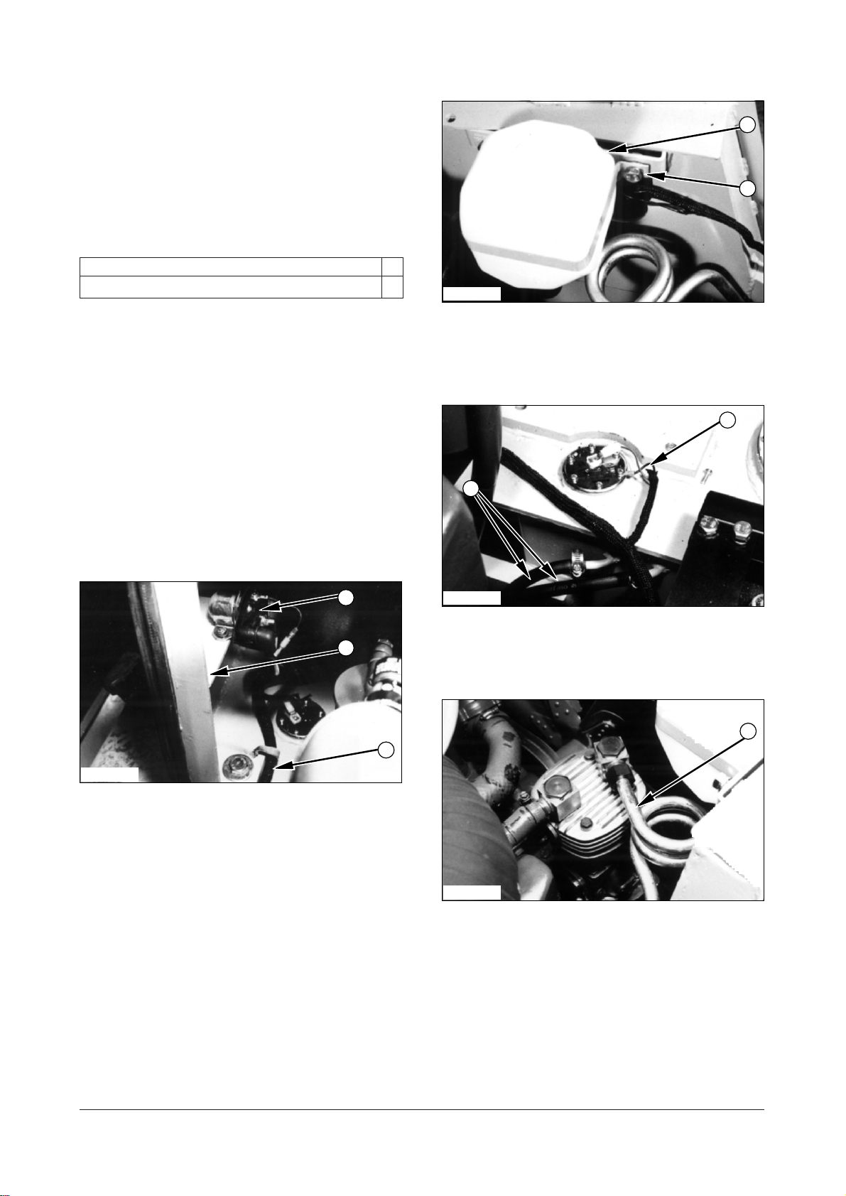
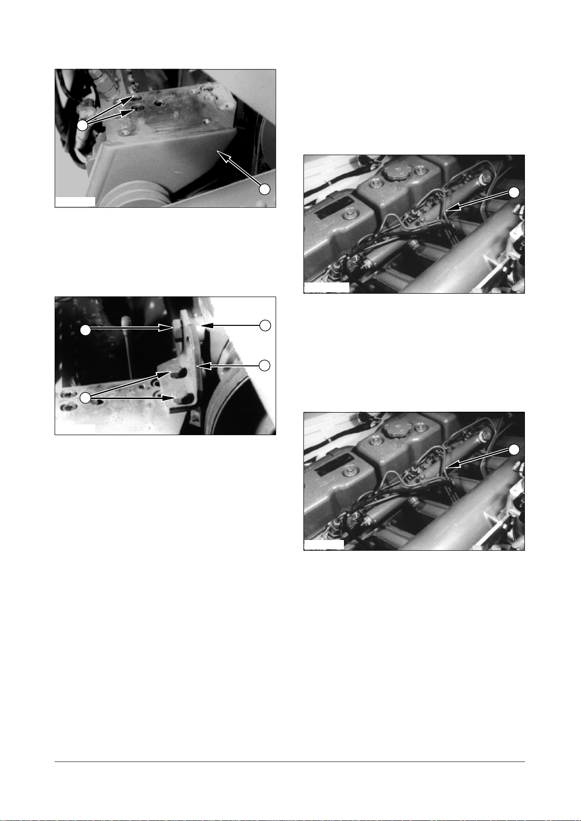
1. Drain the coolant from the radiator.
5. Remove bolts (4), washers and nuts that hold
coolant reservoir on the frame. Set coolant
reservoir (5) aside.
IEED003P
6. Disconnect two hoses (6) from the fuel tank.
7. Disconnect wiring harness (7) from fuel sender.
IEED001P
2. Remove engine harness assembly (1) from the
clips of bonnet assembly (3).
3. Remove screws, washers and circuit breaker (2)
from bonnet assembly (3).
4. Remove bolt and washer that hold bonnet
assembly. Remove bonnet assembly (3) from the
frame.
DE08TS Diesel Engine Disassembly and Assembly
5 of 76
IEED004P
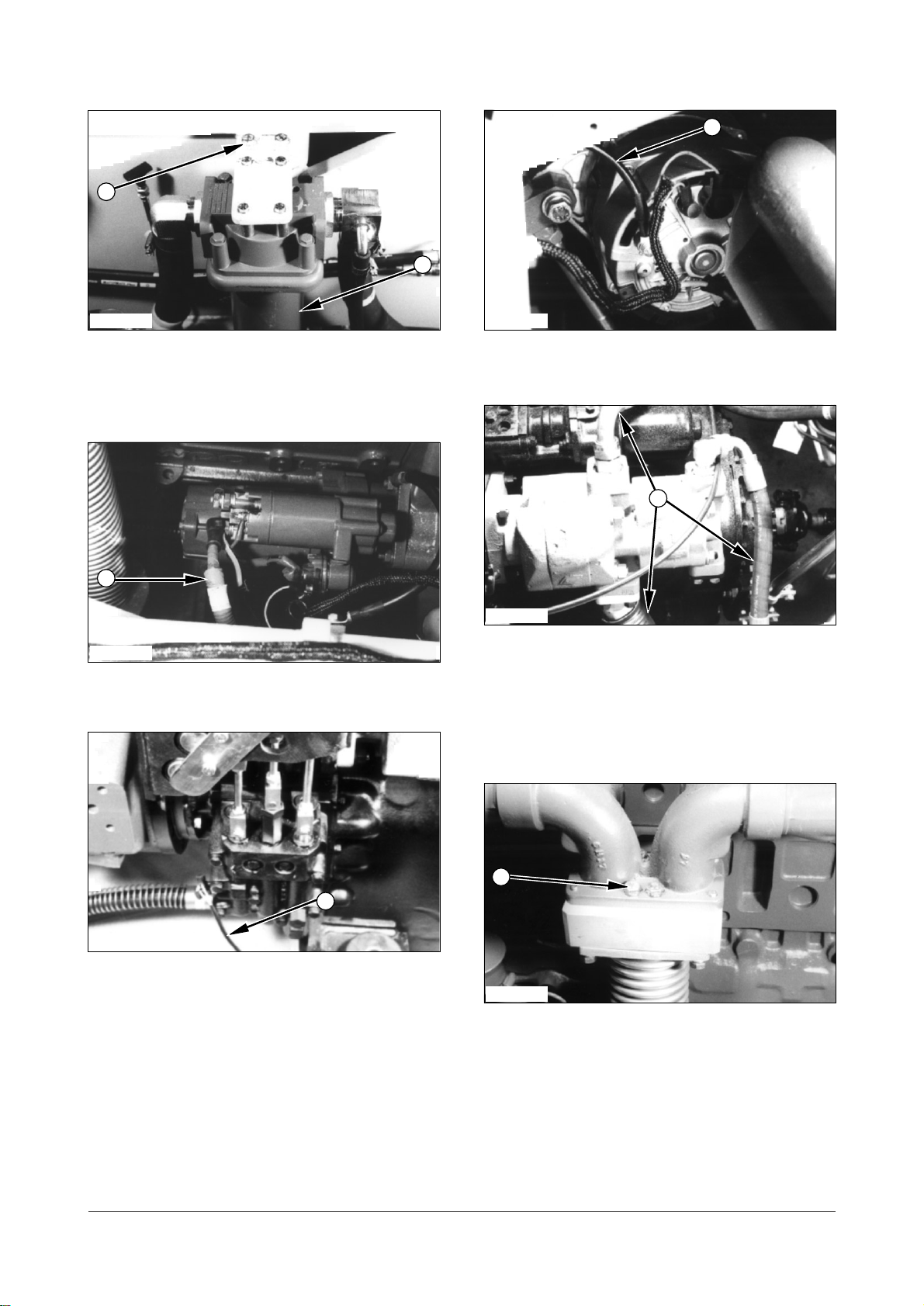
8. Remove tube (8) from the tube of air compressor
(if equipped).
IEED005P IEED008P
9
11
14
15
12
10
13
9. Remove two bolts washers (9) and hydraulic filter
assembly (10). Set hydraulic filter assembly (10)
aside.
IEED006P
10. Disconnect battery cable (11) from the starting
motor.
12. Disconnect ground cable (13) from the alternator.
IEED009P
13. Disconnect three hoses (14) from the hydraulic
pump.
NOTE : Plug and cap all hydraulic connectors and hoses
to avoid debris and contamination from entering the
system.
IEED007P
11. Disconnect transmission neutral switch connector
IEED010P
(12).
14. Remove bolts (15) and washers that hold the
muffler expansion on exhanst manifold of the
engine.
DE08TS Diesel Engine Disassembly and Assembly
6 of 76
IEED011P IEED014P
17
16
21
18
22
A
20
19
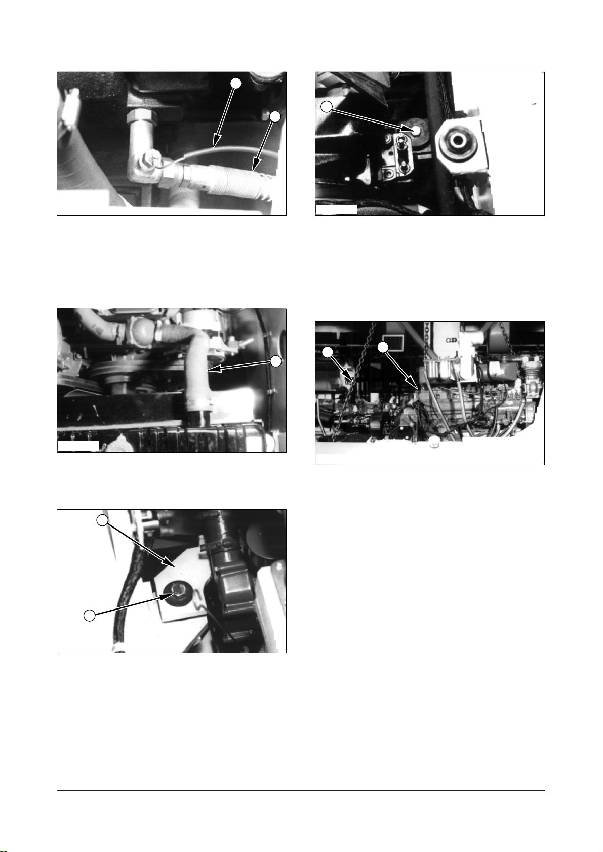
15. Disconnect two transmission cooling hoses (16)
from the transmission.
16. Disconnect transmission oil temperature switch
wiring (17).
IEED012P
17. Disconnect two engine cooling hoses (18 ) from
the engine.
19. Remove bolts (21), washers and nuts from the
two transmission support.
NOTE : At this point, make a final check to be sure all
removals and disconnections have been made from
the engine and the transmission.
IEED015P
20. Install the tool (A) to the transmission. Fasten tool
(A) to the engine and transmission as shown.
21. Remove engine and transmission (22) from the
lift truck.
22. Put the engine and transmission on an
acceptable engine stand. Remove tool (A).
IEED013P
18. Remove bolts (19), washers, nuts from the two
engine support (20), one on both side of the
engine.
DE08TS Diesel Engine Disassembly and Assembly
7 of 76
IEED016P IEED017P
25
23
A
22
24
25
23
24
21
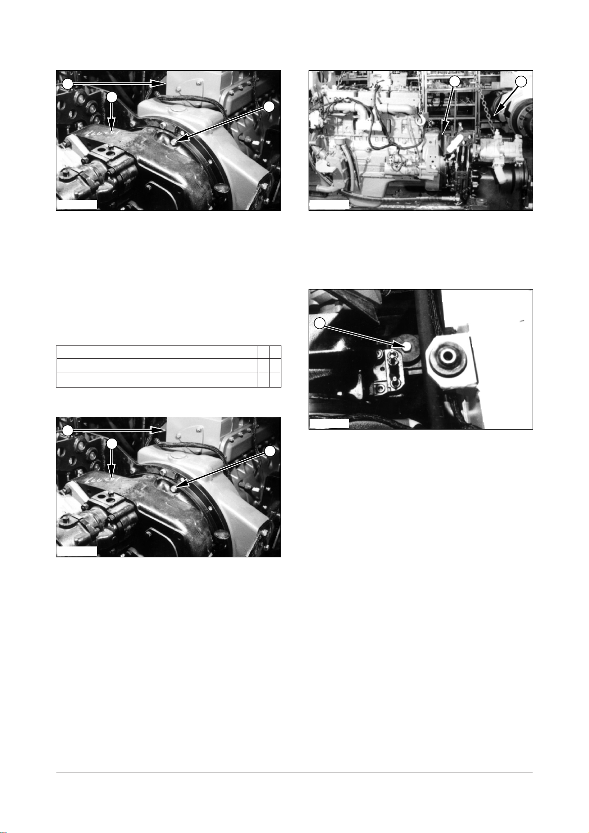
23. Support transmission (24) with fasten a strap and
remove twenty bolts(23) and washers. Remove
transmission (24) from engine (25).
Install Engine And Transmission
A10999 & C40999 - 03
Tools Needed A B
Link Bracket 1
Eye Bolt 1
3. Install the tool (A) to the transmission.
4. Fasten tool (A) to engine and transmission (22) as
shown.
IEED014P
5. Put the engine and transmission in position on the
lift truck. Make an alignment of supports with the
frame.
6. Install bolts (21), washers and nuts that hold the
transmission support to the frame.
Tightenbolts (21) to atorque of
(540
590 lbft).
730800 Nm
IEED016P
1. Put transmission (24) in position in engine (25).
2. Install bolts (23) and washers that hold
transmission to the engine. Tighten bolts (23) to
torque of
DE08TS Diesel Engine Disassembly and Assembly
55 10 Nm (40 7 lbft).
8 of 76
IEED013P
20
19
18
17
16
15
14
IEED011P
7. Install bolts (19), washers and nuts that hold
engine support (20) to the frame. Tighten bolts (19)
to a torque of
IEED012P
280 Nm (205 lbft).
8. Connect two engine cooling hoses (18) and tighten
the hose clamps.
9. Connect two transmission cooling hoses (16) to
transmission.
10. Connect transmission oil temperature switch
connector (17).
IEED010P
11. Install bolts (15) and washers that hold the muffler
expansion to exhaust manifold of the engine.
IEED009P
12. Connect three hydraulic hoses (14) to the
hydraulic pump.
DE08TS Diesel Engine Disassembly and Assembly
9 of 76
IEED008P
13
11
9
10
8
7
6
12
IEED005P
13. Connect ground cable (13) to the alternator.
IEED007P
14. Connect transmission neutral switch connector
(12).
16. Put hydraulic filter assembly (10) in position on
the frame. Install bolts (9) and washers.
IEED004P
17. Install tube (8) to the air compressor (if
equipped).
IEED006P
IEED003P
15. Connect battery cable(11) to the starting motor.
18. Connect wiring harness (7) to the fuel sender.
19. Connect two fuel hoses (6) and tighten the hose
clamp.
DE08TS Diesel Engine Disassembly and Assembly
10 of 76
Electric Starting Motor
1
2
4
3
5
4
2
3
1
WARNING
Remove Electric Starting Motor
A61564 - 02
IEED002P
20. Put the coolant reservoir with bracket (5) in
position on the frame. Install bolts (4) and
washers that hold coolant reservoir (5).
IEED001P
21. Put bonnet assembly (3) in position on the frame.
Install the bolts and washers. Tighten the bolts to
a torque of
200 N..m (150 lb..ft).
Disconnect the battery before the starting motor
is removed
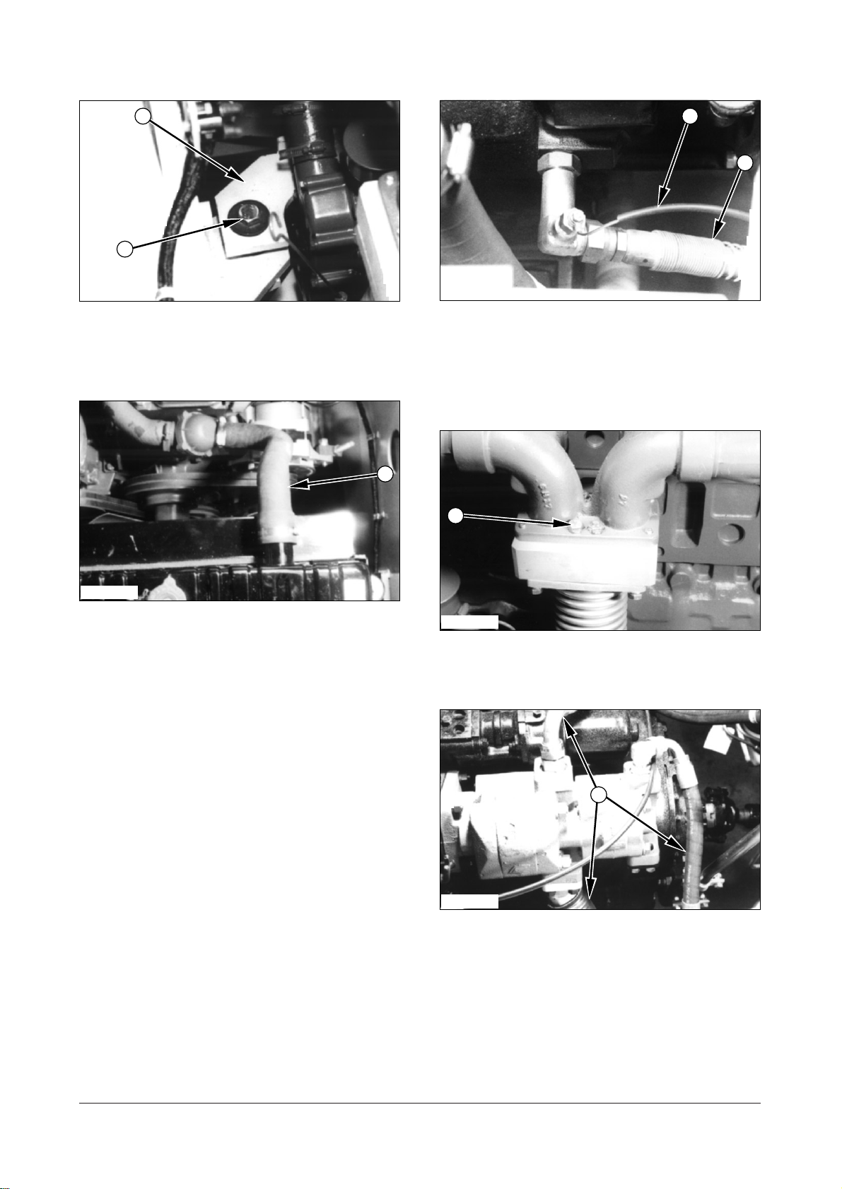
IEED018P
1.
Put identification on the starting motor and
solenoid wires. Disconnect wirings (1) and battery
cable (2).
22. Install the screws and washers that hold circuit
breaker (2).
23. Clear engine harness assembly (1).
24. Fill the cooling system. See the Maintenance
Guide for the correct level.
End By :
a. Install universal joint.
b. Install air cleaner.
c. Install hood.
d. Install floorplate.
e. Install overhead guard.
IEED019P
2. Remove mounting nuts (3) and then remove
starting motor (4) from the lift truck.
DE08TS Diesel Engine Disassembly and Assembly
11 of 76
Install Electric Starting Motor
1
54653
2
6
4
3
1
2
A61564 - 03
IEED019P
Alternator
Remove Alternator B31018 - 02
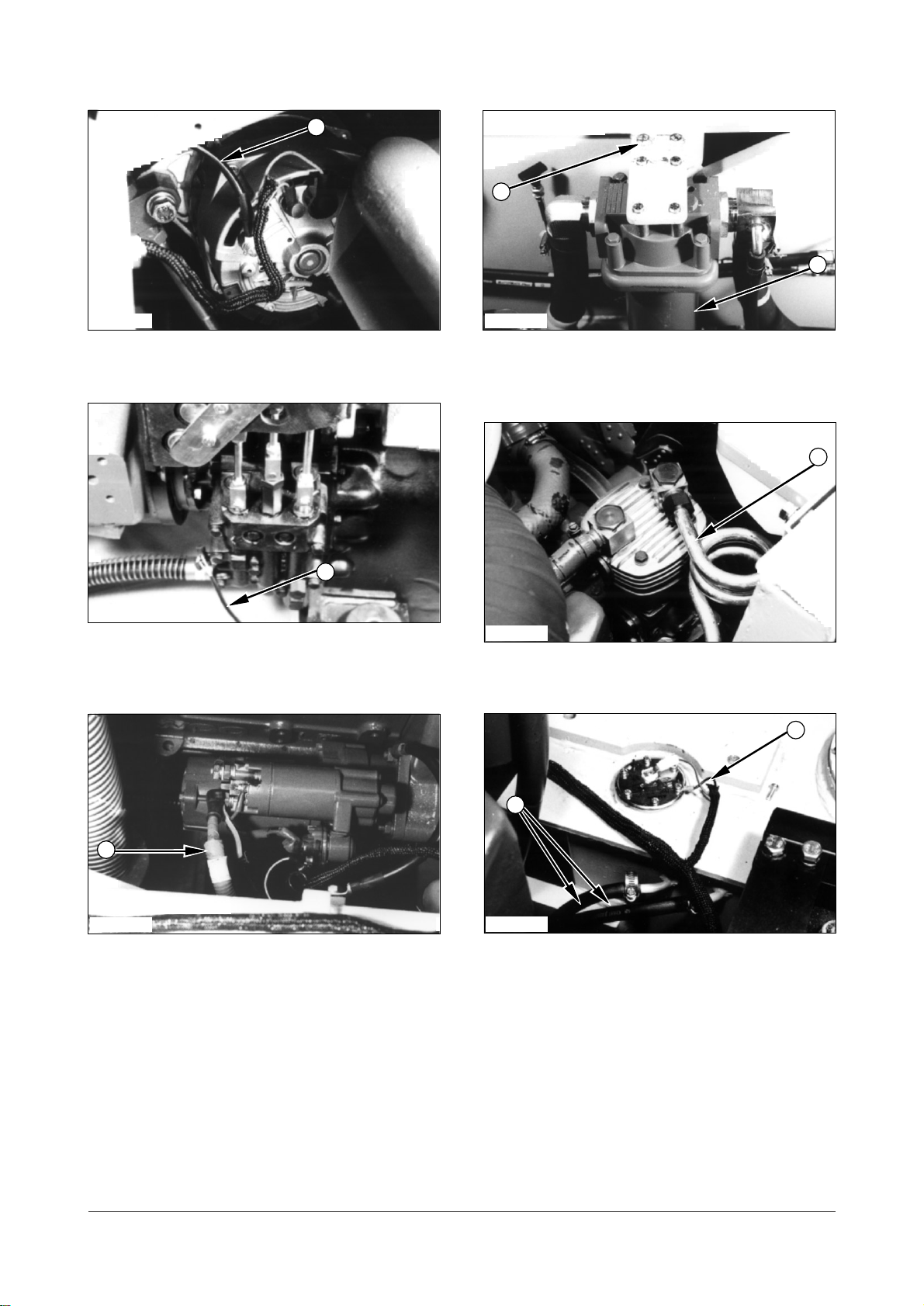
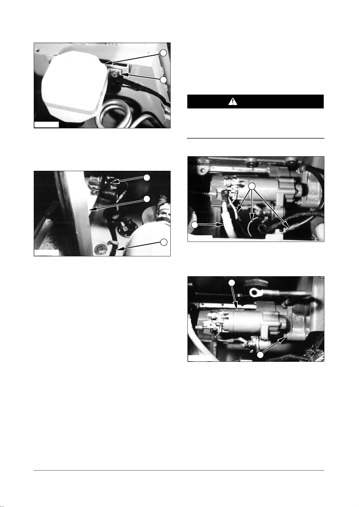
1. Put starting motor (4) in position on the flywheel
housing and install nuts (3) that hold it.
IEED018P
2. Connect wirings (2) to the starting motor and
solenoid. Connect battery positive cable (1).
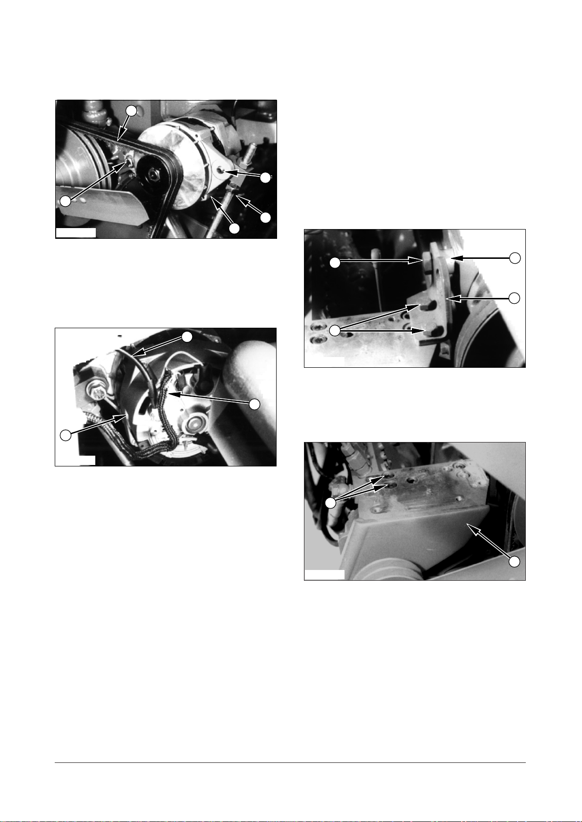
IEED020P
1. Put identification on all wires (1) and the
disconnect them from alternator (6).
2. Disconnect ground cable (2) from alternator (6).
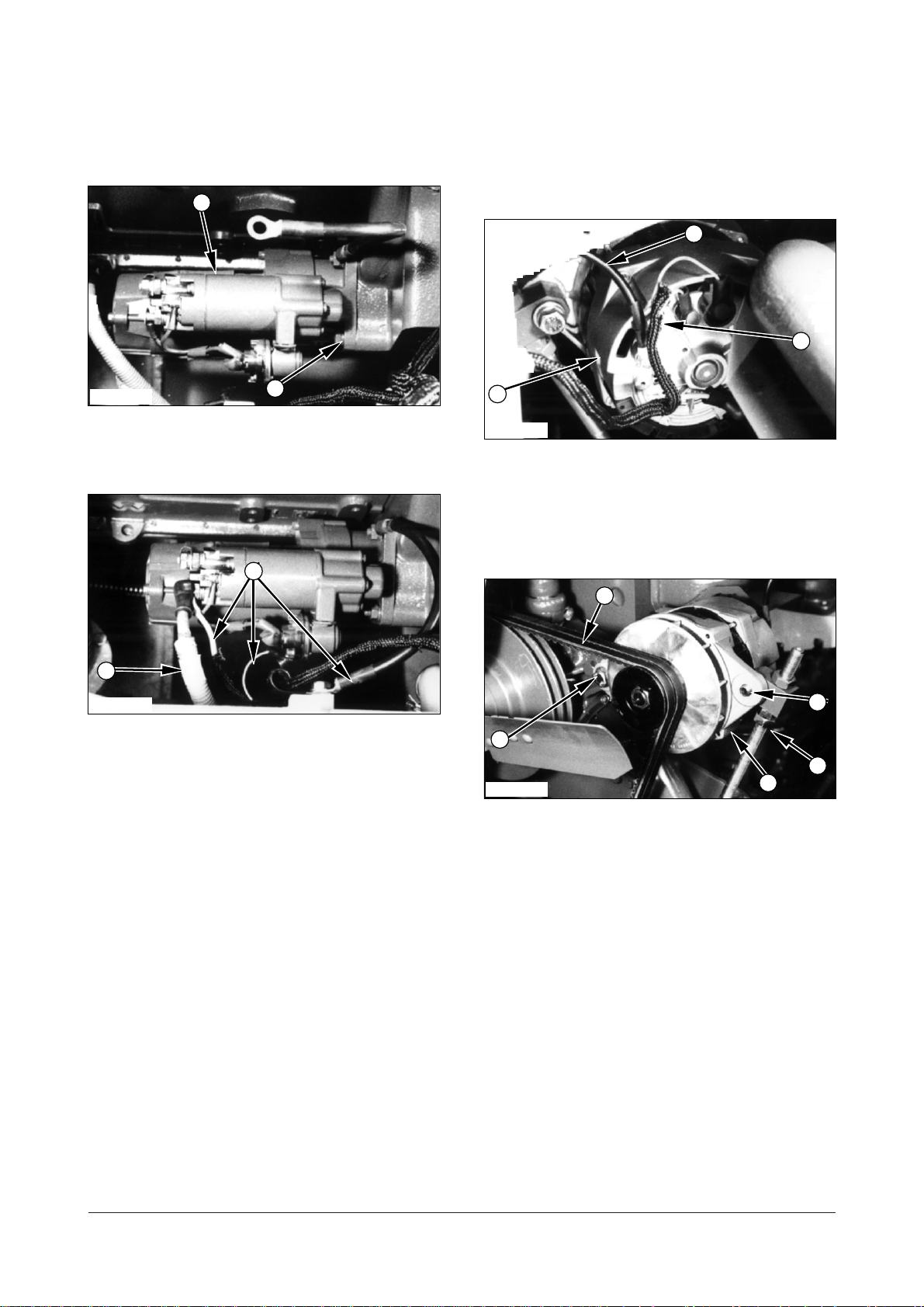
IEED021P
3. Loosen nuts (4) and then remove belt (3) from the
alternator.
4. Remove bolts (5) from the alternator’s bracket to
remove alternator (6).
DE08TS Diesel Engine Disassembly and Assembly
12 of 76
Install Alternator B31018 - 03
1
6
5
3
4
1
2
6
2
546
5
3
IEED021P
1. Put alternator (6) in position on its bracket and
install bolts (5) that hold it.
2. Install fan belt (3) on the alternator and tighten nuts
(4).
Fuel Injection Pump
Remove Fuel Injection Pump
A25663 - 02
Start By :
a. Remove air compressor (if equipped).
b. Remove intake manifold.
IEED020P
3. Connect all wires (1) to their respective positions.
4. Connect ground cable (2) to alternator (6).
IEED022P
1. Remove two bolts (1) and washers.
2. Remove bolt (2), washers, spacer (3) and lifting
bracket (4).
IEED166P
3. Remove bolts (5) and washers that hold the
tension adjusting bracket on the timing gear case.
4. Remove the idle pulley and V-belt tension
adjusting bracket assembly (6) and gasket.
Discard the gasket.
DE08TS Diesel Engine Disassembly and Assembly
13 of 76
IEED023P
12
8
7
9
1414141513
10
11
9
IEED118P
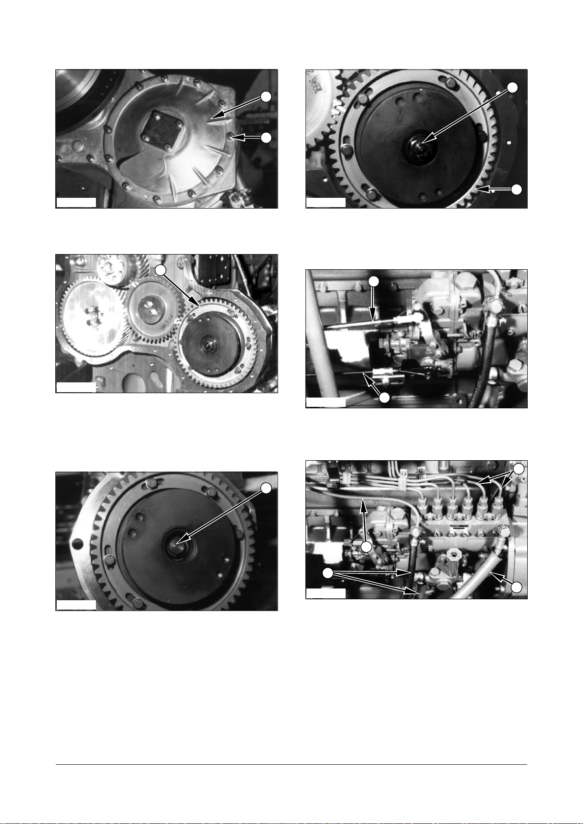
5. Remove bolts (7), washers and cover (8).
IEED024P
6. Make an alignment of the timing marks on fuel
injection pump gear (9) and the idle gear or put a
mark of identification on the gears for correct
installation.
8. Remove nut (11) and injection pump coupling and
gear (9) from the injection pump.
IEED025P
9. Disconnect accel rod (12) and engine stop cable
(13).
IEED026P
IEED117P
10. Disconnect five hoses (14) and tubes (15) from
7. Remove nut (10) from the injection pump coupling.
DE08TS Diesel Engine Disassembly and Assembly
14 of 76
the injection pump.
17
IEED027P
16
16
18
17
9
11. Remove four nuts (16) and washers that hold the
injection pump in place. Remove the gasket and
discard it.
Install Fuel Injection Pump
A25663 - 03
IEED028P
1. Install the new gasket in position on the timing
gear case. Put fuel injection pump (17) in position
on the timing gear case.
IEED028P
12. Support injection pump (17). Remove two bolts
(18) and washers that hold injection pump (17) on
the block. Remove injection pump (17).
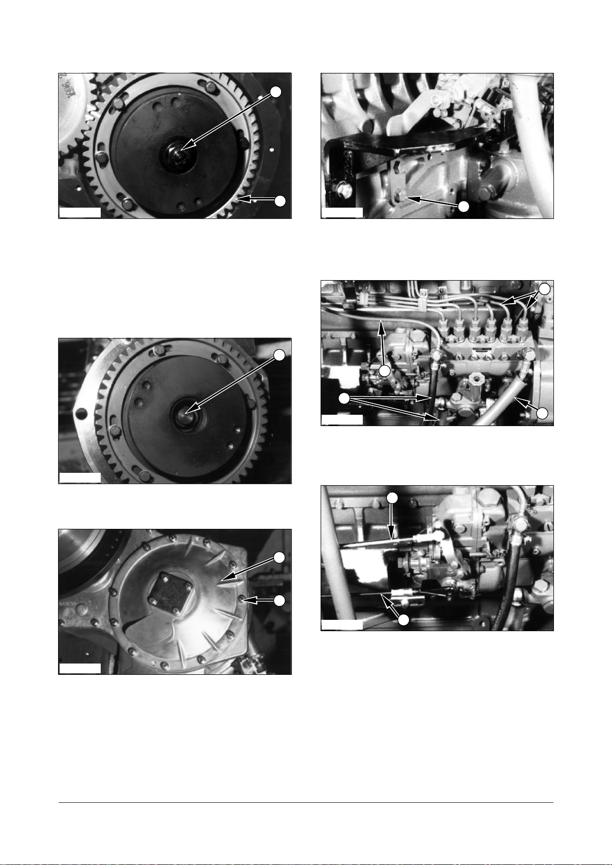
IEED024P
2. Make sure the timing marks or the marks that were
put on the fuel injection pump gear (9) and the idle
gear are in alignment.
IEED027P
3. Install four nuts (16) and washers that hold the fuel
injection pump on the timing gear case.
DE08TS Diesel Engine Disassembly and Assembly
15 of 76
141414
15
12
13
18
8
7
10
IEED118P
11
9
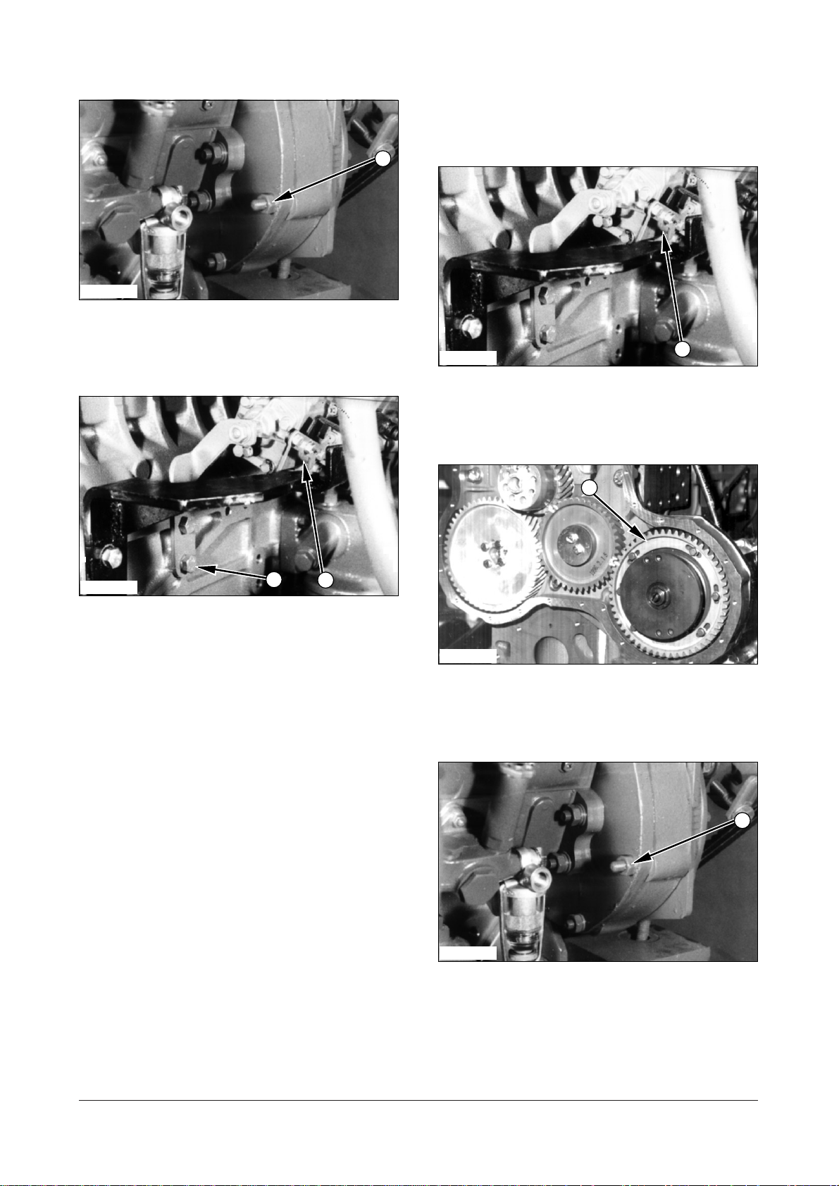
IEED028P
4. Put the fuel injection pump drive coupling and gear
(9) in position. Make an alignment of the key and
the groove (slot) in the coupling.
5. Install nut (11) that hold the injection pump drive
coupling and gear (9) in place. Tighten nut (11) to
a torque of
IEED117P
130 Nm (96 lbft).
6. Install nut (10) into the injection pump coupling.
8. Install bolts (18) and washers that hold the
injection pump on the block.
IEED026P
9. Connect three hoses (14) and tube (15) to the
injection pump.
IEED025P
10. Connect accel cable (12) and engine stop cable
IEED023P
(13) to the injection pump.
7. Install cover (8), bolts (7) and washers.
DE08TS Diesel Engine Disassembly and Assembly
16 of 76
1
1
IEED166P
5
6
3
4
1
2
11. Install the new gasket on the timing gear case.
12. Put the idle pulley and V-belt tension adjusting
bracket assembly (6) on the timing gear case and
install bolts (5) and washers.
Fuel Injection Lines
Remove Fuel Injection Lines
A23525 - 02
IEED029P
1. Disconnect fuel injection lines (1) from the fuel
injection nozzle assemblies and the fuel injection
pump.
IEED022P
13. Install lifting bracket (4), spacer (3), washers and
bolts (2) on the block.
14. Install two bolts (1) and washers.
End By :
a. Install air compressor (if equipped).
b. Install intake manifold.
Install Fuel Injection Lines
A23525 - 03
IEED029P
2. Connect fuel injection lines (1) to the fuel injection
pump and the fuel injection nozzle assemblies.
Tighten the fuel line nuts toa torque of
16 to20 Nm (12 to 15 lbft).
DE08TS Diesel Engine Disassembly and Assembly
17 of 76
Fuel Filter
2
1
3
4
1
2
2
1
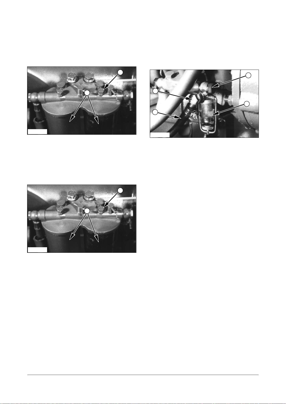
Remove Fuel Filter A21357SE - 02
Fuel Strainer
Remove & Install Fuel Strainer
A21357PR - 01
IEED030P
1. Loosen bolt (1). Remove bowl (2).
2. Remove fuel filter.
Install Fuel Filter A21357SE - 03
IEED030P
1. Install a new gasket in the filter bowl.
IEED031P
1. Remove bolt (1) and washers and disconnect fuel
line (2) that connected the fuel tank.
2. Remove bolt (3), washers and fuel strainer (4) from
the injection pump.
3. Install fuel strainer (4) in reverse order of removal.
2. Put a new fuel filter element in position.
3. Put filter bowl (2) in position and tighten bolt (1)
that holds the bowl in position.
DE08TS Diesel Engine Disassembly and Assembly
18 of 76
Fuel Pump
2
1
2
1
3
4
3
4
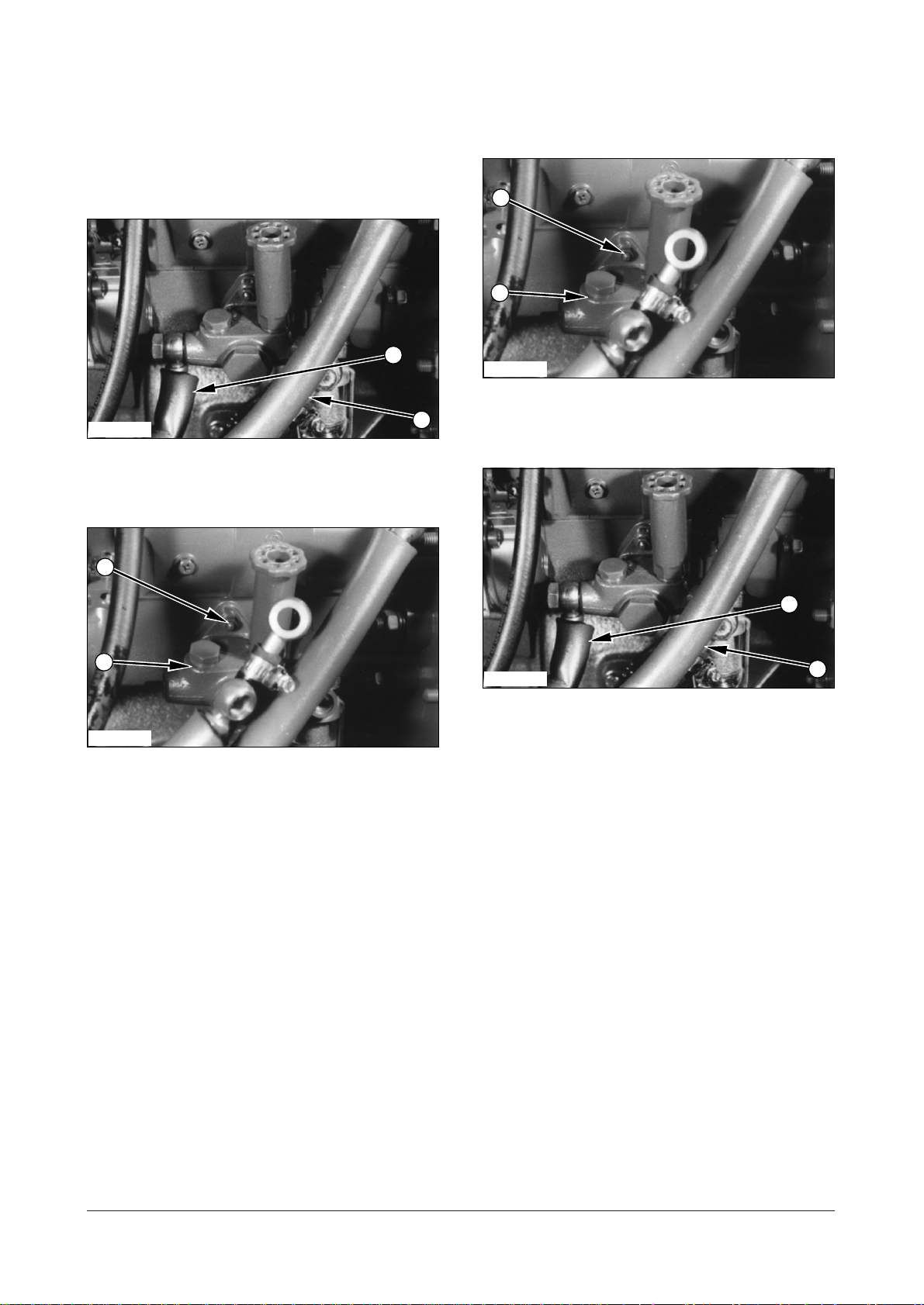
Remove Fuel Pump A21663 - 02
IEED032P
1. Disconnect fuel inlet line (1) and fuel outlet line (2)
from the fuel pump.
Install Fuel Pump A21663 - 03
IEED033P
1. Put fuel pump (4) in position on the engine block
with nuts (3) that hold it.
IEED033P
2. Remove three nuts (3) that hold fuel pump (4) to
the injection pump. Remove fuel pump (4).
IEED032P
2. Connect fuel outlet line (2) and fuel inlet line (1) to
the fuel pump.
DE08TS Diesel Engine Disassembly and Assembly
19 of 76
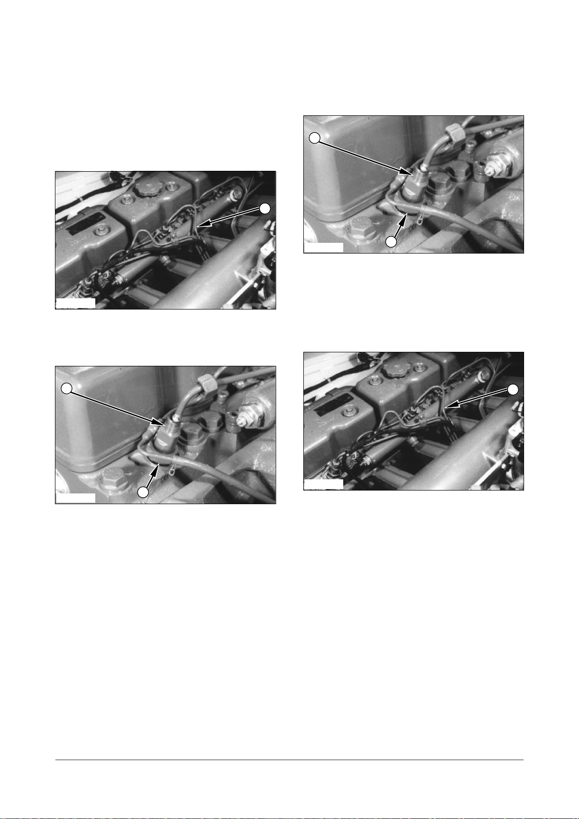
Fuel Injection Nozzle
1
1
2
3
2
3
Assembly
Remove Fuel Injection Nozzle
Assembly A28999 - 02
IECD029P
1. Disconnect fuel lines (1) from the fuel injection
nozzles.
Install Fuel Injection Nozzle
Assembly A28999 - 03
IEED034P
1. Install the new seal rings in the nozzle hole of the
cylinder head.
2.Put fuel injection nozzles (2) in position. Install nuts
(3) and tighten them to a torque of
(52
7 lbft).
7010 Nm
IEED034P
2. Remove nuts (3) and then remove fuel injection
nozzles (2).
3. Remove the seals from the nozzle holders of the
cylinder head and discard it.
IEED029P
3. Connect fuel lines (1) to the injection nozzles and
then tighten the nuts to a torque of
30 Nm (22 lbft).
DE08TS Diesel Engine Disassembly and Assembly
20 of 76

Disassemble & Assemble Fuel
1
1
6
4
2
3
5
7
6
4
2
3
5
7
Injection Nozzle Assembly
A28999 - 06
Start By :
a. Remove fuel injection nozzle assembly
IEED035P
1. Remove union nut (1) from the nozzle assembly.
IEED036P
4. Install shims (7), spring (6), guide (5) and
intermediate washer (4) to the nozzle holder.
5. Install needle valve (3) into fuel nozzle (2) and
install the fuel nozzle.
IEED036P
2. Remove fuel nozzle (2), needle valve (3),
intermediate washer (4), guide (5), spring (6) and
shims (7) from the nozzle holder.
3. Check all parts for damage. If damaged, use new
parts for replacement.
NOTE : The following steps are for assembling the
fuel injection nozzle assembly.
IEED035P
6. Install union nut (1) and tighten to a torque of
7010 Nm (527 lbft).
End By :
a. Install fuel injection nozzle assembly.
DE08TS Diesel Engine Disassembly and Assembly
21 of 76
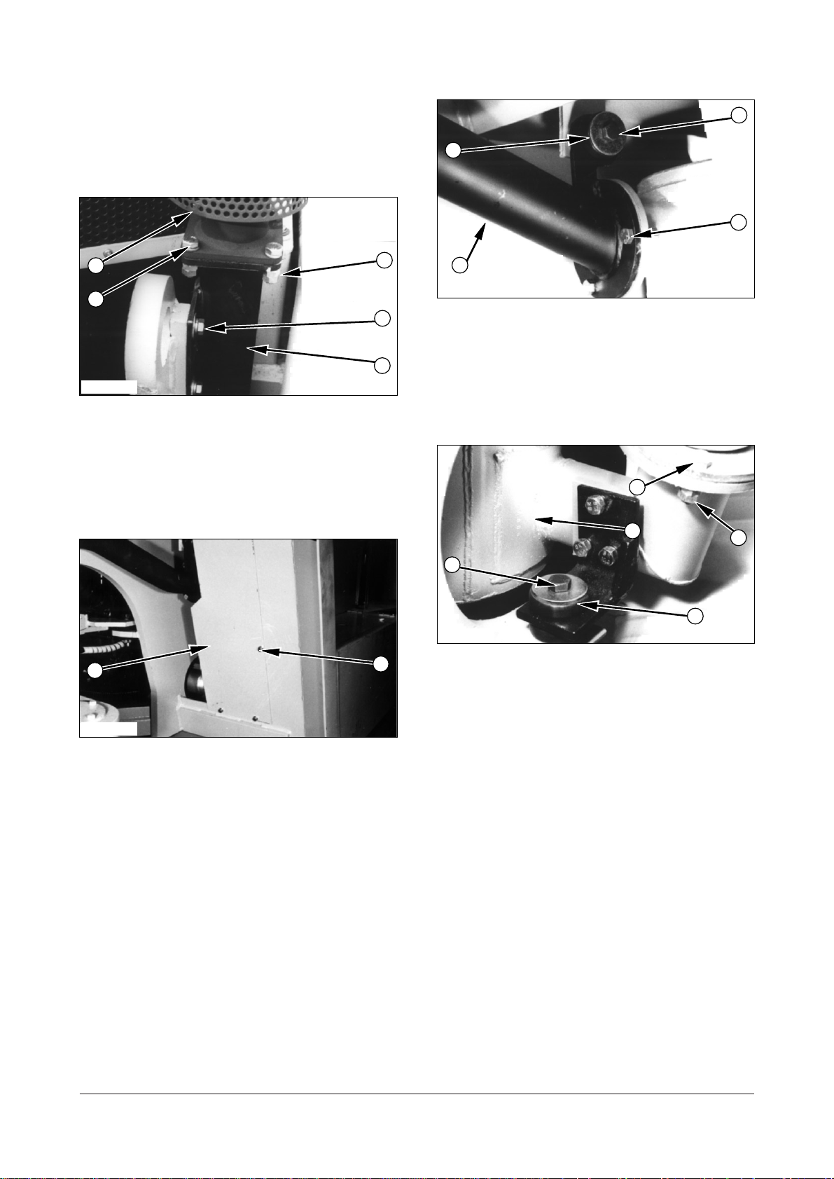
Muffler
2
8
15
12
11
14
13
5
9
10
4
5
6
7
3
1
Remove Muffler A32570 - 02
IEED037P
1. Remove four bolts (1), washers and nuts (2) that
hold muffler tube assembly (3) on tube assembly
(5).
2. Remove two bolts (4) and washers that hold tube
assembly (5) on the frame.
IEED039P
4. Remove three bolts (8), washers and nuts.
5. Support tube assembly (5) and remove bolt (9),
washers, rubber mounts (10), shims and nuts that
hold tube assembly (5) on the frame. Remove tube
assembly (5).
IEED038P
3. Remove five bolts (6), washers and cover (7) from
the frame.
IEED040P
6. Remove three bolts (11), washers and nuts (12).
7. Remove bolt (13), washers, rubber mounts (14),
shims and nuts that hold mount bracket of muffler
assembly (15) on the frame. Remove muffler
assembly (15).
DE08TS Diesel Engine Disassembly and Assembly
22 of 76
 Loading...