

DoorKing 6500 Series, 6500-380, 6500-381, 6500-384, 6500-385 Installation & Owner's Manual
...
Installation/Owner’s Manual
Series 6500
Series 6500
Series 6500
Vehicular Swing Gate Operator
Use this manual for circuit board 4405-018 Revision A or higher.
Entrapment Protection must be provided for the gate system where the risk of entrapment or obstruction exists. The operator
will NOT run without one or more monitored type B1 or B2 entrapment protection devices in EACH entrapment area.
6500-065-J-7-18
UL 325 August 2018 Standard
THIS PRODUCT IS TO BE INSTALLED AND SERVICED BY A TRAINED GATE SYSTEMS TECHNICIAN ONLY.
Visit
www.dkslocator.com
Date Installed:
Installer/Company Name:
Phone Number:
Leave Manual with Owner
Conforms To UL STD 325
Certified To CSA STD C22.2 # 247
to find a professional installing and servicing dealer in your area.
Circuit Board
Serial Number
and Revision Letter:
Copyright 2018 DoorKing, Inc. All rights reserved.
Copyright 2009 DoorKing, Inc. All rights reserved.
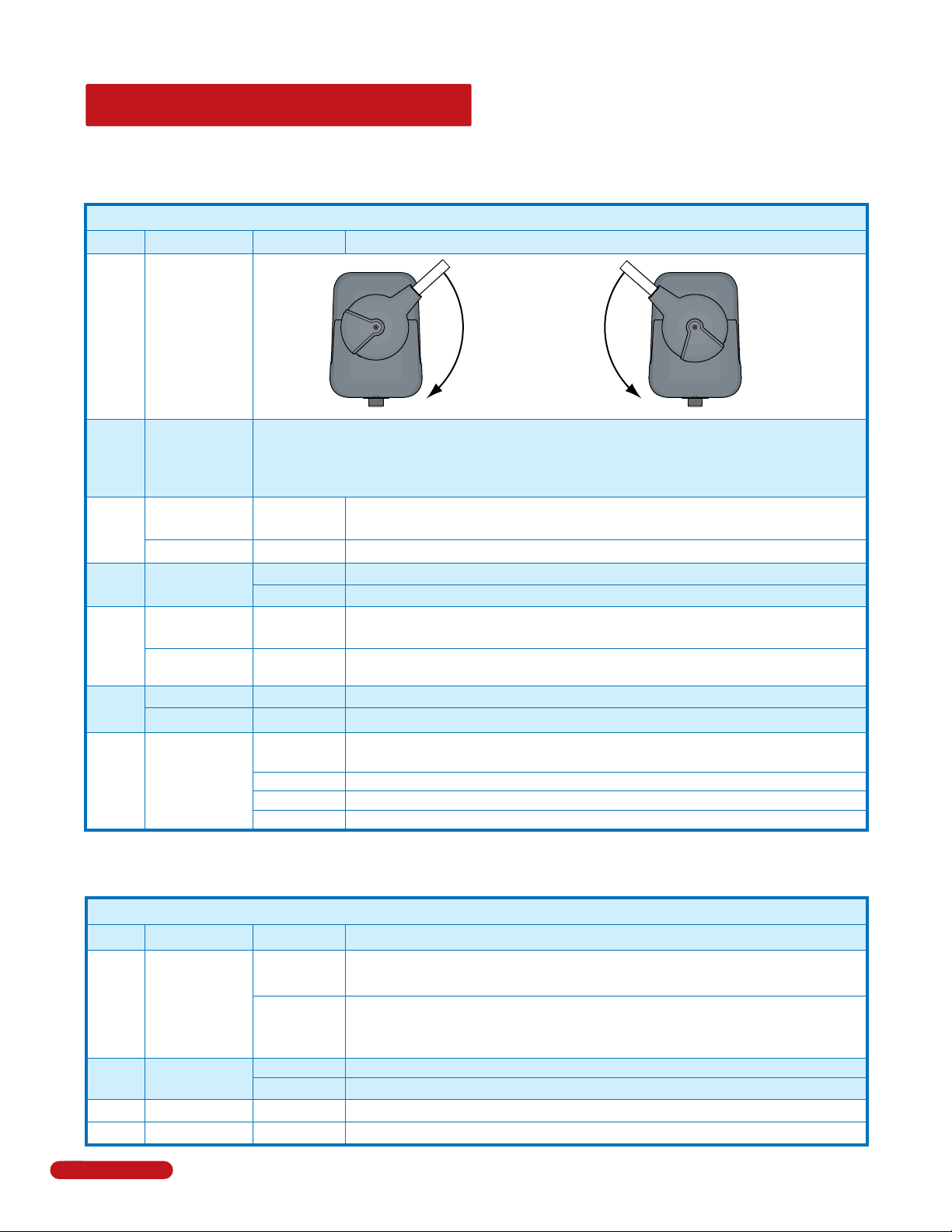
QUICK GUIDE: DIP-Switches
The two DIP-switches located on the circuit board are used to program the operator to operate in various modes and to turn on
or off various operating features. Whenever a switch setting is changed, power to the operator must be turned OFF and then
turned back on for the new setting to take affect. Check and review ALL switch settings prior to applying power to the operator.
See page 22 for more information about DIP-switches.
SW 1 (Top 8 Switches)
Switch Function Setting Description
Primary 6500
1
2
3
4
5
6
7 and 8
Changes Gate
Opening
Direction
Secondary 6500
Changes Gate
Opening
Direction
Exit Loop Port
Output
Full Open Input
Auto-Close
Timer
Reverses Gate
External Shadow
Loop Detector
Single Operator
Dual Operators
Circuit
Board
Relay
Opens
Clockwise
7-OFF
8-OFF
7-OFF
7-ON
7-ON
8-ON
8-OFF
8-ON
ON OFF
Same as above, for secondary 6500 ONLY.
The output wired to terminal #4 becomes the output from the exit loop detector
OFF
plugged into the EXIT Loop port.
Normal Setting. Terminal #4 is a normal full open input.
ON
Auto-close timer is OFF. Manual input required to close gate.
OFF
Normal Setting. Auto-close timer is ON. Adjustable from 1-23 seconds.
ON
Normal Setting. Input to terminal #6 and reverse loop will stop and reverse gate to
OFF
the full open position during the close cycle ONLY.
Input to terminal #6 becomes a SHADOW loop input. It is only active when the gate
ON
is fully opened. (Shadow loop setting when external loop detector is used)
Normal Setting. Switch must be OFF for single operator.
OFF
Switch must be ON when primary/secondary (dual) gates are used.
ON
Normal Setting. Relay activates when gate is at open limit.
(Shadow loop setting when DoorKing Plug-In loop detector is used)
Relay activates when gate is not closed.
Relay activates when gate is opening and open.
Relay activates during opening and closing cycle.
Opens
Counter-Clockwise
See page 22 for ALL DIP-switch definitions and typical settings.
SW 2 (Bottom 4 Switches)
Switch Function Setting Description
Primary and secondary operators start at the same time (Normal setting for single
OFF
1
2
3
4
2
Quick Guide - 1
Gate Overlap
Magnetic lock
gate operator).
The secondary operator will start 1.5 sec. before primary operator during open
ON
cycle and the primary operator will start 1.5 sec. before the secondary operator
during the close cycle (Normal setting for bi-parting gate operators).
Normal Setting. Magnetic lock is not used.
OFF
Magnetic lock is used and connected to terminals 9 and 12. See page 27 for wiring.
ON
Normal Setting. Switch 3 MUST be turned OFF for Model 6500 operator.
OFF
Normal Setting. Switch 4 MUST be turned OFF for Model 6500 operator.
OFF
6500-065-J-7-18

See pages 27 and 28 for
terminal wiring.
4-Pin Non-Removable Terminal
Open LED
Close LED
Stop LED
3-Pin with
Jumper
Jumper on bottom
2 pins when using
4-pin terminal.
1
2
3
4
Jumper on top 2 pins
when NOT using
4-pin terminal.
1
2
UL 325
3 4
Terminal
Pages 16,17,28
1
2
3
4
1477-010
NC NO
2
4
5
6
7
OB
CB
8
OE
CE
G
G
3
4
5
6
7
8
9
10
11
12
Relay
Contacts
13
14
15
16
17
18
19
20
20
QUICK GUIDE: Terminal Descriptions
Open N.O.
Close N.O.
Stop N.C.
Common
20-Pin Main Terminal
Notes:
• Use a standard 4-wire 3-button
control station.
DoorKing’s 3-wire 3-button
control station cannot be used.
• When using a 3-button control
station AND a interlock device
together, #3 terminal (N.C.) must
be wired in series.
• See page 27 for wiring.
Low Voltage Common
Full Open
24 VAC - 250 mA max.
(See note below)
Full Open
Full Open
Standard Reverse
Gate Tracker Data
Gate Tracker Busy
24 VDC Mag Lock Power
Dry Relay Contact
Dry Relay Contact
Low Voltage Common
Low Voltage Common
Entrapment Alarm
Alarm Reset
Secondary Current Sensor
Motor
Motor
Circuit Board Power
Circuit Board Power
DANGER
HIGH VOLTAGE!
ON
1
NO
2 3 4 5 6 7 8
1
2 3 4 5 6 7 8
1
2 3 4 5 6 7 8
1
2 3 4 5 6 7 8
SW 1
ON
SW 1
ON
SW 1
ON
SW 1
• lf SW 1, switch 3 is ON, functions as a
normal full open input (Normal setting).
4
5
6
10
16
• lf SW 1, switch 3 is OFF, input to
terminal #4 becomes the output from the
EXIT loop detector plugged into the EXIT
loop port. (Used for specialized functions).
• When gate is closed, input will open gate.
• When gate is open and auto close timer SW 1,
switch 4 is turned ON, input will re-set and hold
timer.
• When gate is open and auto close timer SW 1,
switch 4 is turned OFF, input will close gate.
• When gate is closing, input will reverse gate.
This input ONLY functions when gate is
fully opened or in the closing cycle.
• When gate is closing: SW 1, switch 5 is
OFF, an input to terminal #6 will stop and
reverse and the gate to the full open position.
Note: If the auto-close timer is ON, when gate
reaches the open position, timer will not
close the gate. Another input command is
needed to reset and close the gate (Normal
Setting).
• SW 1, switch 5 ON, an input to terminal #6
(e.g.: external loop detector connected) becomes a
SHADOW loop input. It is only active when the gate is
fully opened.
9
11
24-volt DC magnetic lock power is
provided constantly except when the
gate is opening or open (Normally
Closed function). 1 Amp Max.
Operation of the circuit board dry
relay contact is dependent on
setting of SW 1, switches 7 and 8.
Relay contacts can be set for
Normally Open (NO) or
Normally Closed (NC)
operation.
Contact rating is
1 amp maximum
at 24-volts DC.
Relay Not Available when using DoorKing
plug-In shadow loop detector.
NC
For dual operator applications
ONLY. Allows the secondary
reversing sensor to monitor
the current flow into the
secondary operator. See page
25 for more information.
Terminal #3 Note:
Exceeding 250 mA of power from this terminal may
cause the circuit board transformer to overheat,
causing intermittent problems.
6500-065-J-7-18
Quick Guide - 2
3
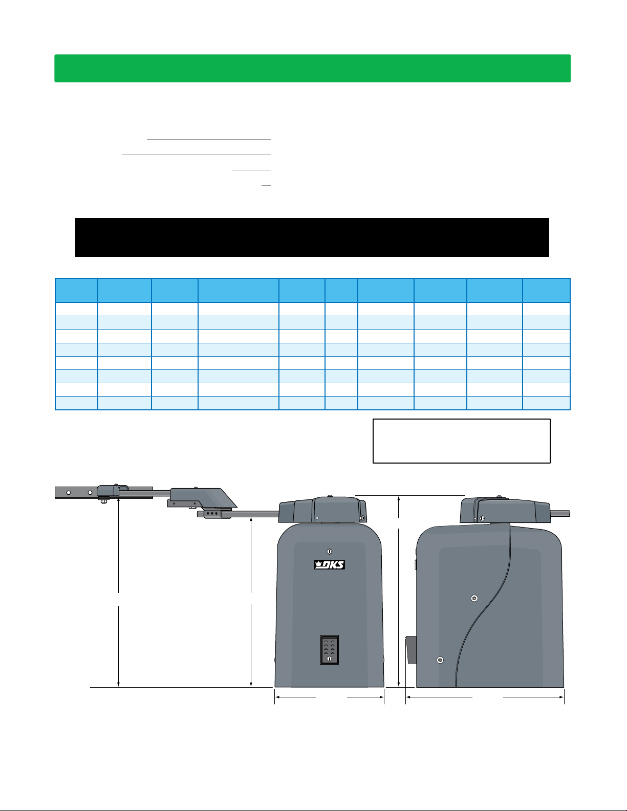
SPECIFICATIONS
Use this manual for the Model 6500 operators with circuit board 4405-018 Rev A or higher ONLY.
Class of Operation Model 6500 - UL325 Class I, II, III, IV
Type of Gate Vehicular Swing Gates Only
Inherent Entrapment Protection Device Inherent Reverse Sensor System (Type A)
External Entrapment Protection Device Inputs Connection inputs for Non-contact Sensor - Photo Sensor (Type B1)
(Monitored Inputs) Connection input for Contact Sensor - Reversing Edge (Type B2)
Entrapment Protection must be provided for the gate system where the risk of entrapment or obstruction exists.
The operator will not run without one or more monitored type B1 or B2 entrapment protection devices in EACH
entrapment area.
Model #
6500-380
6500-381
6500-382
6500-383
6500-384
6500-385
6500-386
6500-387
Note: 208/230/460/575 VAC input voltage can be connected to the
operator by installing an “Optional” High Voltage Kit (P/N 2600-266).
Convenience
Open
No
No
Yes
Yes
No
No
Yes
Yes
Type
Operator
Primary
Secondary
Primary
Secondary
Primary
Secondary
Primary
Secondary
Horsepower - Volts
1/2 HP - 115 VAC
1/2 HP - 115 VAC
1/2 HP - 115 VAC
1/2 HP - 115 VAC
1 HP - 115 VAC
1 HP - 115 VAC
1 HP - 115 VAC
1 HP - 115 VAC
1-Phase
1-Phase
1-Phase
1-Phase
1-Phase
1-Phase
1-Phase
1-Phase
AmpPhase
5.4
5.4
5.4
5.4
9.7
9.7
9.7
9.7
Max Gate
Weight
600 Lbs.
600 Lbs.
600 Lbs.
600 Lbs.
800 Lbs.
800 Lbs.
800 Lbs.
800 Lbs.
Type of wiring to be used on ALL external devices:
A) Type CL2, CL2P, CL2R, or CL2X.
B) Other cable with equivalent or better electrical,
mechanical, and flammability ratings.
31
5
/8
Max Gate
Length
18 Ft.
18 Ft.
18 Ft.
18 Ft.
22 Ft.
22 Ft.
22 Ft.
22 Ft.
”
Cycles Per
Hour
60
60
60
60
60
60
60
60
Speed
90°
12-14 Sec
12-14 Sec
12-14 Sec
12-14 Sec
12-14 Sec
12-14 Sec
12-14 Sec
12-14 Sec
3
/8
28
31”
DoorKing, Inc. reserves the right to make changes in the products described in this manual without notice and without obligation of DoorKing, Inc. to notify any persons
of any such revisions or changes. Additionally, DoorKing, Inc. makes no representations or warranties with respect to this manual. This manual is copyrighted, all rights
reserved. No portion of this manual may be copied, reproduced, translated, or reduced to any electronic medium without prior written consent from DoorKing, Inc.
4
”
3
/8
18
” 23
1
/4
”
6500-065-J-7-18

TABLE OF CONTENTS
QUICK GUIDES
Quick Guide: DIP-Switches
Quick Guide: Terminal Descriptions
Quick Guide - 1
Quick Guide - 2
SPECIFICATIONS
Swing Gate Requirements
Swing Gate Protection
ASTM F2200 Standard for Gate Construction
Important Safety Instructions
Instructions regarding intended installation:
Important Notices
UL 325 Entrapment Protection
Glossary
Previous Page
SECTION 1 - INSTALLATION 8
1.1 Underground Conduit Requirements
1.2 Concrete Pad
1.3 Installation Layouts
1.4 Overlapping Bi-Parting Gate Operator Positions
1.5 Securing Operator to Pad
1.6 Attach Gate Bracket
1.7 Determining Arm Lengths
1.8 Installation of Warning Signs
1.9 Entrapment Protection Installation
9-12
16-17
SECTION 2 - AC POWER TO OPERATOR(S) 18
2.1 High Voltage Wire Run
2.2 High Voltage Terminal Connection
2.3 Bi-Parting Gates Wiring - Dual Gate Operators
SECTION 3 - ADJUSTMENTS 20
3.1 4405 Circuit Board Descriptions and Adjustments
3.2 DIP-Switch Settings for 4405 Circuit Board
3.3 Limit Sensors
3.4 Inherent Reverse Sensors Adjustment
3.5 Secondary Current Sensor Adjustment
21-22
2
3
4
4
4
5
6
7
8
8
13
14
14
15
15
18
18
19
20
23
24
25
6500-065-J-7-18
SECTION 4 - WIRING 26
4.1 Terminal Descriptions
4.2 Control Wiring
4.3 Entrapment Protection Wiring
4.4 Loop Detector Wiring
SECTION 5 - OPERATING INSTRUCTIONS 30
5.1 Power and Reset Switch
5.2 Shutdown Conditions
5.3 Manual Gate Operation
31-32
32-33
SECTION 6 - MAINTENANCE AND TROUBLESHOOTING 34
6.1 Maintenance
6.2 Troubleshooting
6.3 Built-in Diagnostics
6.4 Accessory Items
6.5 Gearbox Shaft Extension Replacement
Model 6500’s Wiring Diagrams
35-36
40-42
SECTION 7 - OWNER OF THE GATE OPERATOR 43
7.1 Alarm Sounding and Gate WILL NOT Operate
7.2 Manual Gate Operation
7.3 Gate Operators Monthly Checkup
Printable Safety Page
26
27
28
29
30
34
37
38
39
43
44
45
47
1
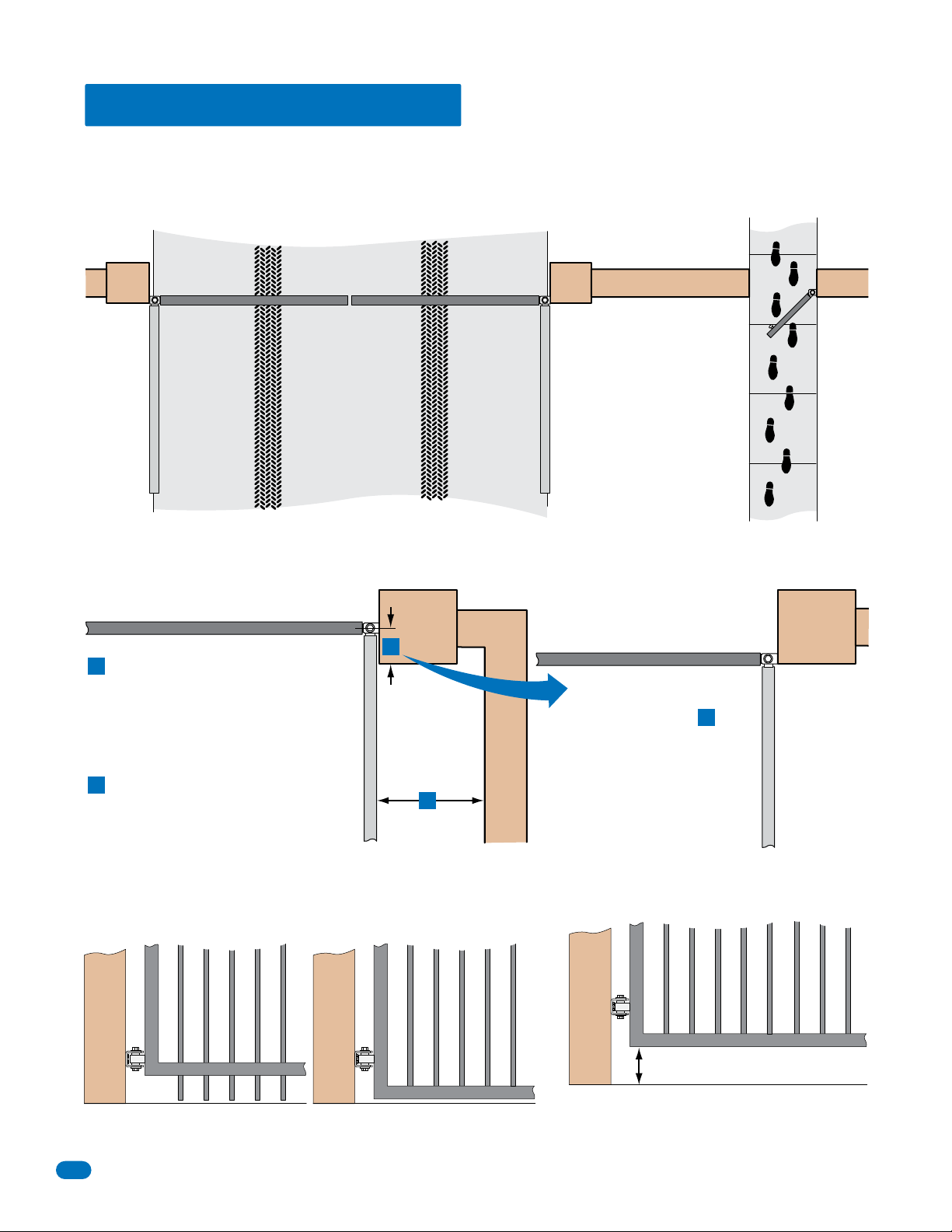
Swing Gate Requirements
The operator is intended for installation only on gates used for vehicles. Pedestrians must be supplied with a separate
access opening. The pedestrian access opening shall be designed to promote pedestrian usage. Locate the gate such that
persons will not come in contact with the vehicular gate during the entire path of travel of the vehicular gate.
Closed Gates
Closed Gate
If distance is greater than 4 inches,
A
entrapment protection for this area is
required.
If distance is less than 16 inches,
B
entrapment protection in this area
is required.
Not Allowed OK
A
B
Opened Gate
Closed Gate
With the hinge mounted on
the corner of the pilaster,
the entrapment area is
eliminated and protection
is NOT required for this
area.
A
Opened Gate
6 inches to 16 inches
If bottom of gate is 6” to 16”above the ground
Gates shall have smooth bottom edges, with vertical
bottom edged protrusions not exceeding 0.50 inches.
2
at any part of the gate’s traveling path,
entrapment protection for this area is required.
6500-065-J-7-18

Swing Gate Protection
Reverse Loop
Minimizes the potential of the gate
closing when a vehicle is present.
Number and placement of loops is
dependent on the application.
D
C
Moving Gate Can Cause
Serious Injury or Death
KEEP CLEAR! Gate may move at any time
without prior warning.
Do not let children operate the gate or play
in the gate area.
This entrance is for vehicles only.
Pedestrians must use separate entrance.
C
Non-contact Sensor
Minimizes the potential
of the gate closing on
vehicular or other traffic
that loops cannot sense.
Monitored device helps
protect against
entrapment when
needed.
D
Warning Signs
Permanently mounted
and easily visible from
either side of the gate.
F
D
Shadow Loop
Provides a hold open command to
the operator(s) only if the gate(s)
are at the full open position.
E
Reverse Loop
Minimizes the potential of the gate
closing when a vehicle is present.
Number and placement of loops is
dependent on the application.
E
E
Non-contact
Sensor
Minimizes the potential
of the gate striking
vehicular or other traffic
that loops cannot sense.
Monitored device helps
protect against
entrapment when
needed.
Separate
Pedestrian
Walkway
Located so
pedestrians
cannot come in
contact with the
vehicular gate.
6500-065-J-7-18
Automatic Exit Loop
(Optional) will provide an open
command to the gate operator(s)
when a vehicle is exiting the
property.
F
Contact Sensor
Minimizes the potential
of the gate striking
vehicular or other traffic
that loops cannot sense.
Monitored device helps
protect against
entrapment when
needed.
External entrapment
protection is REQUIRED
for operator to function.
3

ASTM F2200 Standard for Gate Construction
Vehicular gates should be constructed and installed in accordance with ASTM F2200; Standard Specification for Automated Vehicular Gate Construction.
For a copy of this standard, contact ASTM directly at 610-832-9585; service@astm.org; or www.astm.org.
Important Safety Instructions
WARNING - To reduce the risk of injury or death:
1. READ AND FOLLOW ALL INSTRUCTIONS.
2. Never let children operate or play with gate controls. Keep the remote control away from children.
3. Always keep people and objects away from gate. NO ONE SHOULD CROSS THE PATH OF THE MOVING GATE.
4. Test the operator monthly. The gate MUST reverse on contact with a rigid object or stop or reverse when an object activates the non-contact sensors.
After adjusting the force or the limit of travel, retest the gate operator. Failure to adjust and retest the gate operator properly can increase the risk of
injury or death.
5. Use the emergency release only when the gate is not moving.
6. KEEP GATES PROPERLY MAINTAINED. Read the owner's manual. Have a qualified service person make repairs to gate hardware.
7. The entrance is for vehicles only. Pedestrians must use separate entrance.
8. SAVE THESE INSTRUCTIONS!
Instructions regarding intended installation:
• Install the gate operator only if:
1. The operator is appropriate for the construction of the gate and the usage class of the gate.
2. All openings of a horizontal slide gate are guarded or screened from the bottom of the gate to a minimum of 6 feet (1.83 m) above the ground to
prevent a 2 ¼ inch (57.2 mm) diameter sphere from passing through the openings anywhere in the gate, and in that portion of the adjacent fence
that the gate covers in the open position.
3. All exposed pinch points are eliminated or guarded.
4. Guarding is supplied for exposed rollers.
• The operator is intended for installation only on gates used for vehicles. Pedestrians must be supplied with a separate access opening. The pedestrian
access opening shall be designed to promote pedestrian usage. Locate the gate such that persons will not come in contact with the vehicular gate
during the entire path of travel of the vehicular gate.
• The gate must be installed in a location so that enough clearance is supplied between the gate and adjacent structures when opening and closing to
reduce the risk of entrapment. Swinging gates should not open into public access areas.
• The gate must be properly installed and work freely in both directions prior to the installation of the gate operator. Do not over-tighten the operator
clutch, pressure relief valve or reduce reversing sensitivity to compensate for a damaged gate.
• For gate operators utilizing Type D protection:
1. The gate operator controls must be placed so that the user has full view of the gate area when the gate is moving.
2. A warning placard shall be placed adjacent to the controls.
3. An automatic closing device (such as a timer, loop sensor, or similar device) shall not be employed.
4. No other activation device shall be connected.
• Controls intended for user activation must be located at least six feet (6’) away from any moving part of the gate and where the user is prevented from
reaching over, under, around or through the gate to operate the controls. Outdoor or easily accessible controls should have a security feature to prevent
unauthorized use.
• The Stop and/or Reset button must be located in the line-of-sight of the gate. Activation of the reset control shall not cause the operator to start.
• A minimum of two (2) WARNING SIGNS shall be installed, one on each side of the gate where easily visible.
• For gate operators utilizing a non-contact sensor:
1. See the instructions on the placement of non-contact sensors for each type of application.
2. Care shall be exercised to reduce the risk of nuisance tripping, such as when a vehicle trips the sensor while the gate is still moving in the opening direction.
3. One or more non-contact sensors shall be located where the risk of entrapment or obstruction exist, such as the perimeter reachable by a moving
gate or barrier.
• For gate operators utilizing contact sensors:
1. One or more contact sensors shall be located where the risk of entrapment or obstruction exist, such as at the leading edge, trailing edge, and
post mounted both inside and outside of a vehicular horizontal slide gate.
2. One or more contact sensors shall be located at the bottom edge of a vehicular vertical lift gate.
3. One or more contact sensors shall be located at the pinch point of a vehicular vertical pivot gate.
4. A hardwired contact sensor shall be located and its wiring arranged so that the communication between the sensor and the gate operator is not
subjected to mechanical damage.
5. A wireless contact sensor such as one that transmits radio frequency (RF) signals to the gate operator for entrapment protection functions shall
be located where the transmission of the signals are not obstructed or impeded by building structures, natural landscaping or similar
obstructions. A wireless contact sensor shall function under the intended end-use conditions.
6. One or more contact sensors shall be located at the bottom edge of a vertical barrier (arm).
•
Be sure you have instructed the owner of the gate operator about safe and proper operation and testing of the gate operator.
4
6500-065-J-7-18
Important Notices
Vehicular gate operator products provide convenience and security. However, gate operators must use high levels of force to move gates and most people
underestimate the power of these systems and do not realize the potential hazards associated with an incorrectly designed or installed system.
These hazards may include:
• Pinch points
• Entrapment areas
• Reach through hazards
• Absence of entrapment protection devices
• Improperly located access controls
• Absence of vehicle protection devices
• Absence of controlled pedestrian access
In addition to these potential hazards, automated vehicular gate systems must be installed in accordance with the UL 325 Safety Standard and the ASTM
F2200 Construction Standard. Most people are unaware of, or are not familiar with, these standards. If an automated vehicular gate system is not properly
designed, installed, used and maintained, serious injuries or death can result. Be sure that the installer has instructed you on the proper operation of the
gate and gate operator system.
Be sure that the installer has trained you on proper and safe operation of this gate operating system and about the basic functions of the required
reversing systems associated with your gate operating system and how to test them (see section 7). These include reversing loops, inherent reversing
system, electric edges, photoelectric cells, or other external devices.
• This Owner’s Manual is your property. Keep it in a safe place for future reference.
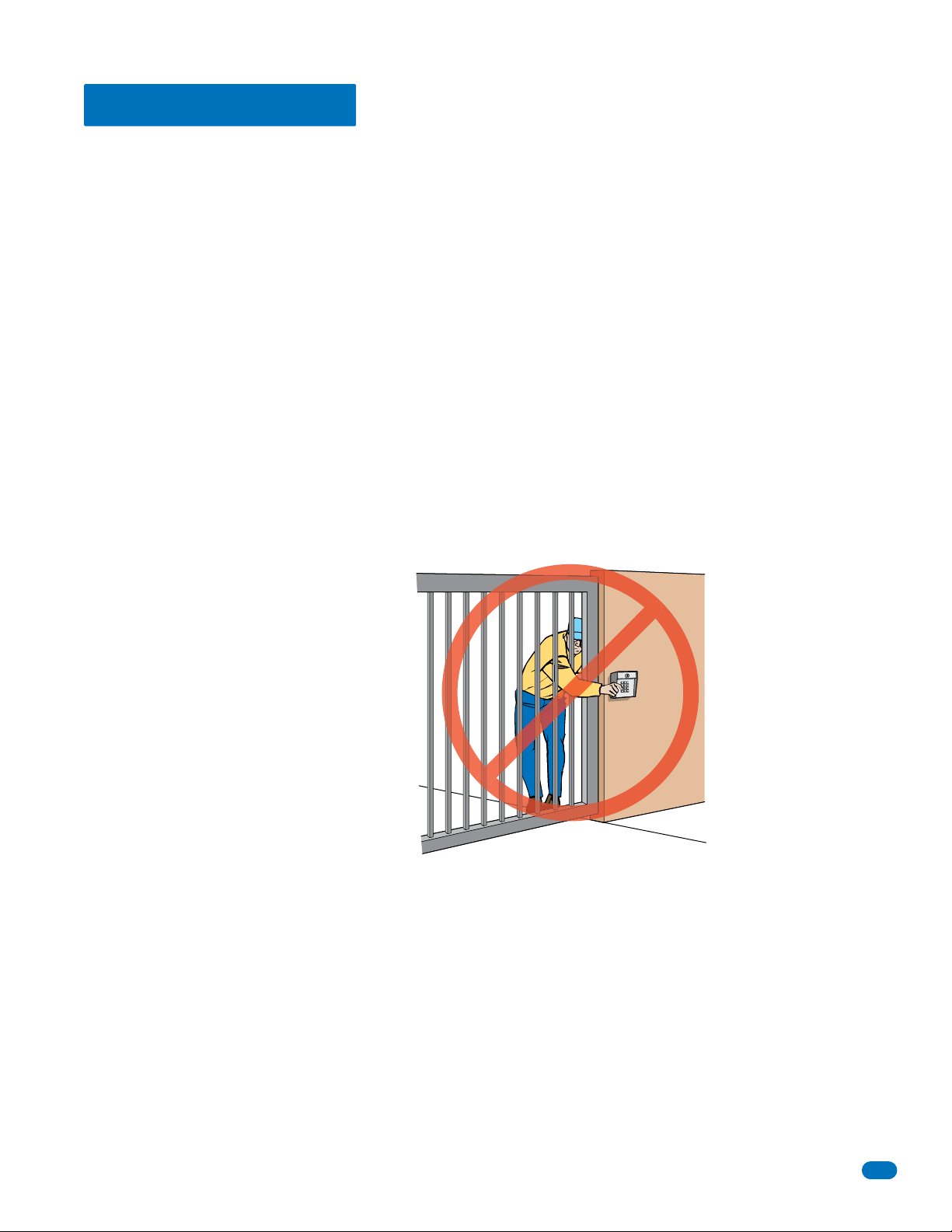
• Be sure that all access control devices are installed a minimum distance of 6 feet away from the gate and gate operator, or in such a way that a
person cannot touch the gate or gate operator while using the device. If access control devices are installed in violation of these restrictions,
immediately remove the gate operator from service and contact your installing dealer.
Opening device MUST be mounted a
minimum of 6 feet from the gate and
NOT accessible through the gate!
• Loops and loop detectors, photo-cells or other equivalent devices must be installed to prevent the gate from closing on vehicular traffic.
• The speed limit for vehicular traffic through the gate area is 5 MPH. Install speed bumps and signs to keep vehicular traffic from speeding
through the gate area. Failure to adhere to posted speed limits can result in damage to the gate, gate operator, and to the vehicle.
• Be sure that all persons who will use the gate system are familiar with the proper use of the gate and gate operator and are familiar with the
possible hazards associated with the gate system.
• Be sure that warning signs are permanently installed on both sides of the gate in an area where they are fully visible to traffic.
• It is your responsibility to periodically check all entrapment protection devices. If any of these devices are observed to function improperly,
remove the operator from service immediately and contact your installing or servicing dealer.
• Follow the recommended maintenance schedule.
• Do not allow children to play in the area of the operator or to play with any gate-operating device.
• To remove the gate operator from service, operate the gate to the full open position and then shut off power to the operator at the service panel.
6500-065-J-7-18
5
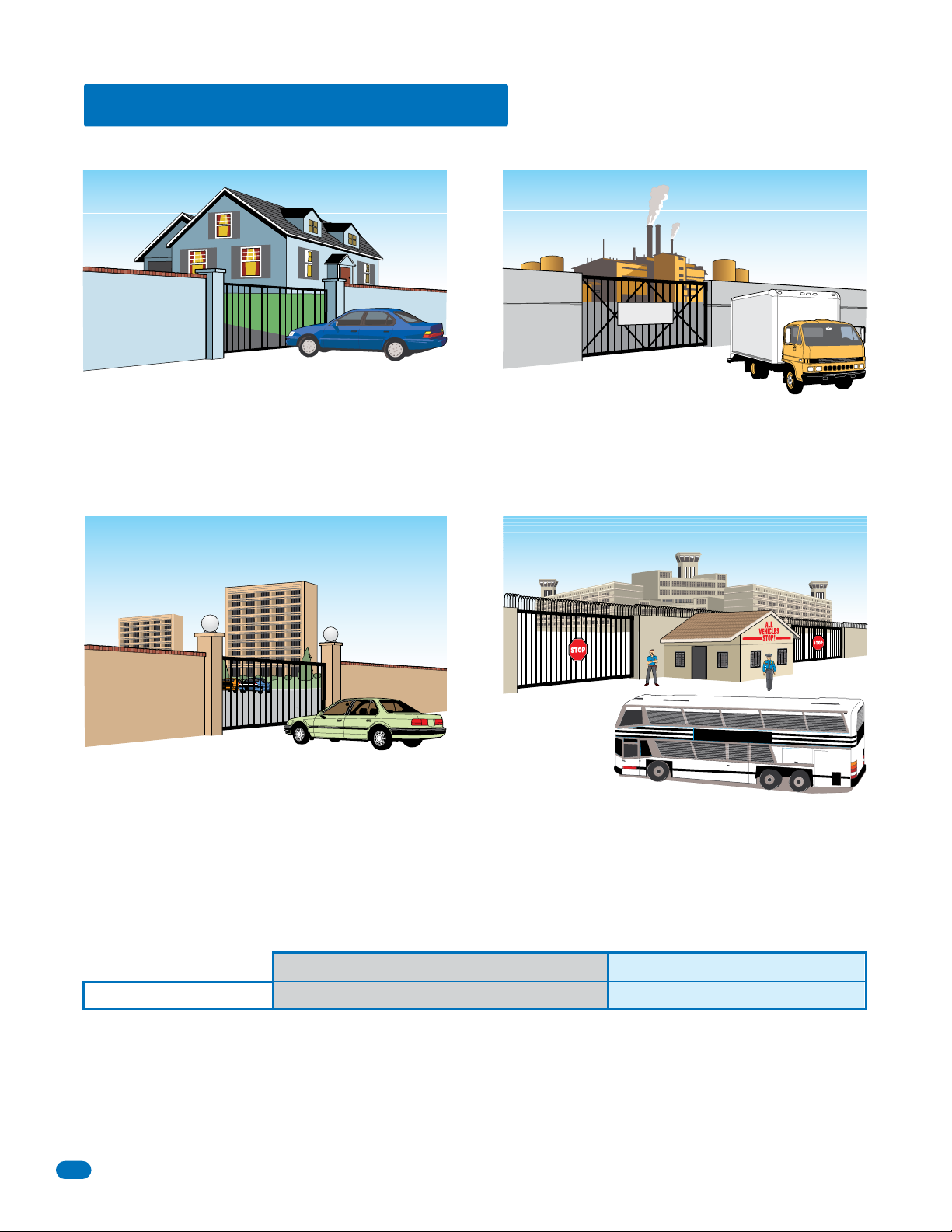
UL 325 Entrapment Protection
UL 325 Classifications
Authorized
Personnel ONLY
Class I - Residential
Vehicular Gate Operator
A vehicular gate operator (or system) intended for use in garages
or parking areas associated with a residence of one-to four single
families.
Class II - Commercial/General Access
Vehicular Gate Operator
A vehicular gate operator (or system) intended for use in a
commercial location or building such as a multi-family housing
unit (five or more single family units), hotel, garages, retail store,
or other buildings accessible by or servicing the general public.
Class III - Industrial/Limited Access
Vehicular Gate Operator
A vehicular gate operator (or system) intended for use in an
industrial location or building such as a factory or loading dock
area or other locations not accessible by or intended to service
the general public.
STATE PRISON
Class IV Restricted Access
Vehicular Gate Operator
A vehicular gate operator (or system) intended for use in a
guarded industrial location or building such as an airport security
area or other restricted access locations not servicing the general
public, in which unauthorized access is prevented via supervision
by security personnel.
Gate Operator Category
Horizontal Slide, Vertical Lift, Vertical Pivot Swing, Vertical Barrier (Arm)
Entrapment Protection Types
Type A - Inherent entrapment protection system.
Type B1 - Non-contact sensor (photoelectric sensor or the equivalent).
Type B2 - Contact sensor (edge device or equivalent).
Type C - Inherent force limiting, inherent adjustable clutch or inherent pressure relief device.
Type D - Actuating device requiring constant pressure to maintain opening or closing motion of the gate.
* B1 and B2 means of entrapment protection must be MONITORED.
6
A, B1*, B2* or D A, B1*, B2*, C or D
Vertical Barrier Note: Barrier gate operators (arm)
that is not intended to move toward a rigid object
closer than 16 inches (406 mm) are not required to
be provided with a means of entrapment protection.
6500-065-J-7-18

Glossary
GATE - A moving barrier such as a swinging, sliding, raising, lowering, or the like, barrier, that is a stand-alone passage
barrier or is that portion of a wall or fence system that controls entrance and/or egress by persons or vehicles and
completes the perimeter of a defined area.
RESIDENTIAL VEHICULAR GATE OPERATOR – CLASS I - A vehicular gate operator (or system) intended for use in a home
of one-to four single family dwelling, or garage or parking area associated therewith.
COMMERCIAL / GENERAL ACCESS VEHICULAR GATE OPERATOR - CLASS II - A vehicular gate operator (or system)
intended for use in a commercial location or building such as a multi-family housing unit (five or more single family units),
hotels, garages, retail store, or other building servicing the general public.
INDUSTRIAL / LIMITED ACCESS VEHICULAR GATE OPERATOR - CLASS III - A vehicular gate operator (or system)
intended for use in an industrial location or building such as a factory or loading dock area or other locations not intended
to service the general public.
RESTRICTED ACCESS VEHICULAR GATE OPERATOR - CLASS IV - A vehicular gate operator (or system) intended for use in
a guarded industrial location or building such as an airport security area or other restricted access locations not servicing
the general public, in which unauthorized access is prevented via supervision by security personnel.
VEHICULAR BARRIER (ARM) OPERATOR (OR SYSTEM) - An operator (or system) that controls a cantilever type device (or
system), consisting of a mechanical arm or barrier that moves in a vertical arc, intended for vehicular traffic flow at
entrances or exits to areas such as parking garages, lots or toll areas.
VEHICULAR HORIZONTAL SLIDE-GATE OPERATOR (OR SYSTEM) - A vehicular gate operator (or system) that controls a
gate which slides in a horizontal direction that is intended for use for vehicular entrance and exit to a drive, parking lot, or
the like.
VEHICULAR SWING-GATE OPERATOR (OR SYSTEM) - A vehicular gate operator (or system) that controls a gate which
moves in an arc in a horizontal plane that is intended for use for vehicular entrance and exit to a drive, parking lot, or the
like.
SYSTEM - In the context of these requirements, a system refers to a group of interacting devices intended to perform a
common function.
WIRED CONTROL - A control implemented in a form of fixed physical interconnections between the control, the associated
devices, and an operator to perform predetermined functions in response to input signals.
WIRELESS CONTROL - A control implemented in means other than fixed physical interconnections (such as radio waves or
infrared beams) between the control, the associated devices, and an operator to perform predetermined functions in
response to input signals.
INHERENT ENTRAPMENT PROTECTION SYSTEM - A system, examples being a motor current or speed sensing system,
which provides protection against entrapment upon sensing an object and is incorporated as a permanent and integral part
of the operator.
EXTERNAL ENTRAPMENT PROTECTION DEVICE - A device, examples being an edge sensor, a photoelectric sensor, or
similar entrapment protection device, which provides protection against entrapment when activated and is not incorporated
as a permanent part of an operator.
ENTRAPMENT - The condition when an object is caught or held in a position that increases the risk of injury.
6500-065-J-7-18
7
SECTION 1 - INSTALLATION
Prior to beginning the installation of the swing gate operator, we suggest that you become familiar with the
instructions, illustrations, and wiring guide-lines in this manual. This will help insure that your installation is
performed in an efficient and professional manner compliant with UL 325 safety and ASTM F2200 construction
standards.
The proper installation of the vehicular swing gate operator is an extremely important and integral part of the
overall access control system.
Check all local building ordinances and building codes prior to installing
this operator. Be sure your installation is in compliance with local codes.
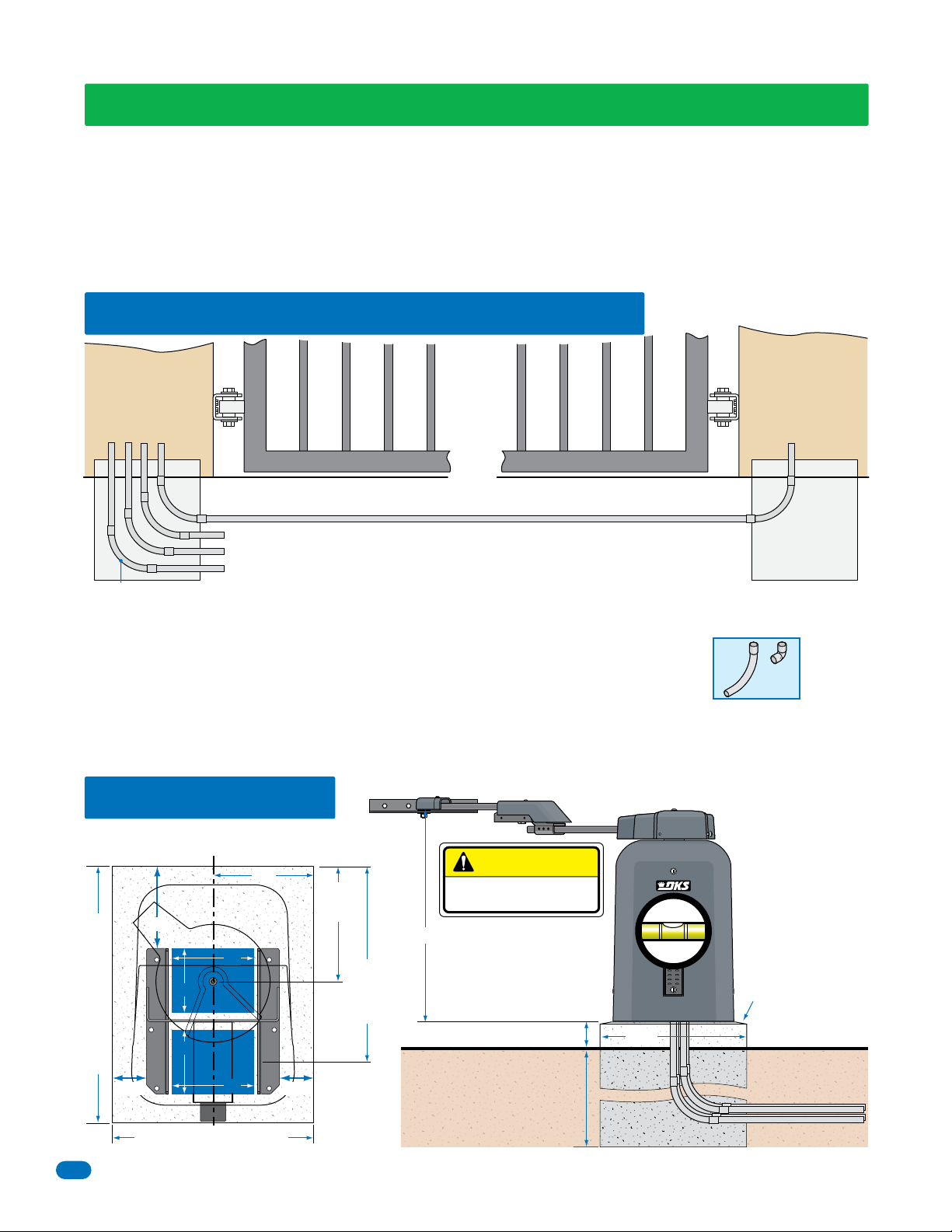
1.1 Underground Conduit Requirements
Primary
Operator
Position
DoorKing’s Primary/Secondary Interconnection Cable (Dual Operator Application Only)
(Secondary Operator AC Power and Communication wires)
External Safety Devices, Controls and P.A.M.S. Wires (Low Voltage wire insulation)
Loop Lead-In Wires (Low Voltage wire insulation)
AC Input Power (High Voltage wire insulation)
Sweeps
• The conduit requirements are for a typical slide gate operator installation (the secondary operator is shown for those
applications where a secondary operator may be used). The conduit requirements for your application may vary from
this depending on your specific needs.
• Use only sweeps for conduit bends. Do not use 90° elbows as this will make wire pulls very
difficult and can cause damage to wire insulation. DoorKing recommends using 3/4-inch conduit.
• External Entrapment Protection is REQUIRED (photo sensor and/or reversing edge).
• Be sure that all conduits are installed in accordance with local codes.
• Never run low voltage rated wire insulation in the same conduit as high voltage rated wire insulation.
Sweep
YES
Secondary
Operator
Position
Concrete Pad
Elbow
NO
1.2 Concrete Pad
Operator and Conduit Location
Center Line
11”
9”
9”
Conduit
7”
Area
7”
Conduit
28” Concrete Pad Length
3.75” 3.75”
22” Concrete Pad Width
8
Area
9”
Power, Reset Box
12.5”
to
center
21.5” to
center
of
conduit
area
CAUTION
NEVER REMOVE HUB
after manual release.
31”
4” minimum
Underground depth of the
concrete pad is determined
by soil conditions and local
building codes. Reinforced
concrete recommended.
Concrete pad
MUST be level.
Note: Bevel the
edges of concrete
pad to eliminate
water puddling
under the operator.
22”
Conduit
6500-065-J-7-18
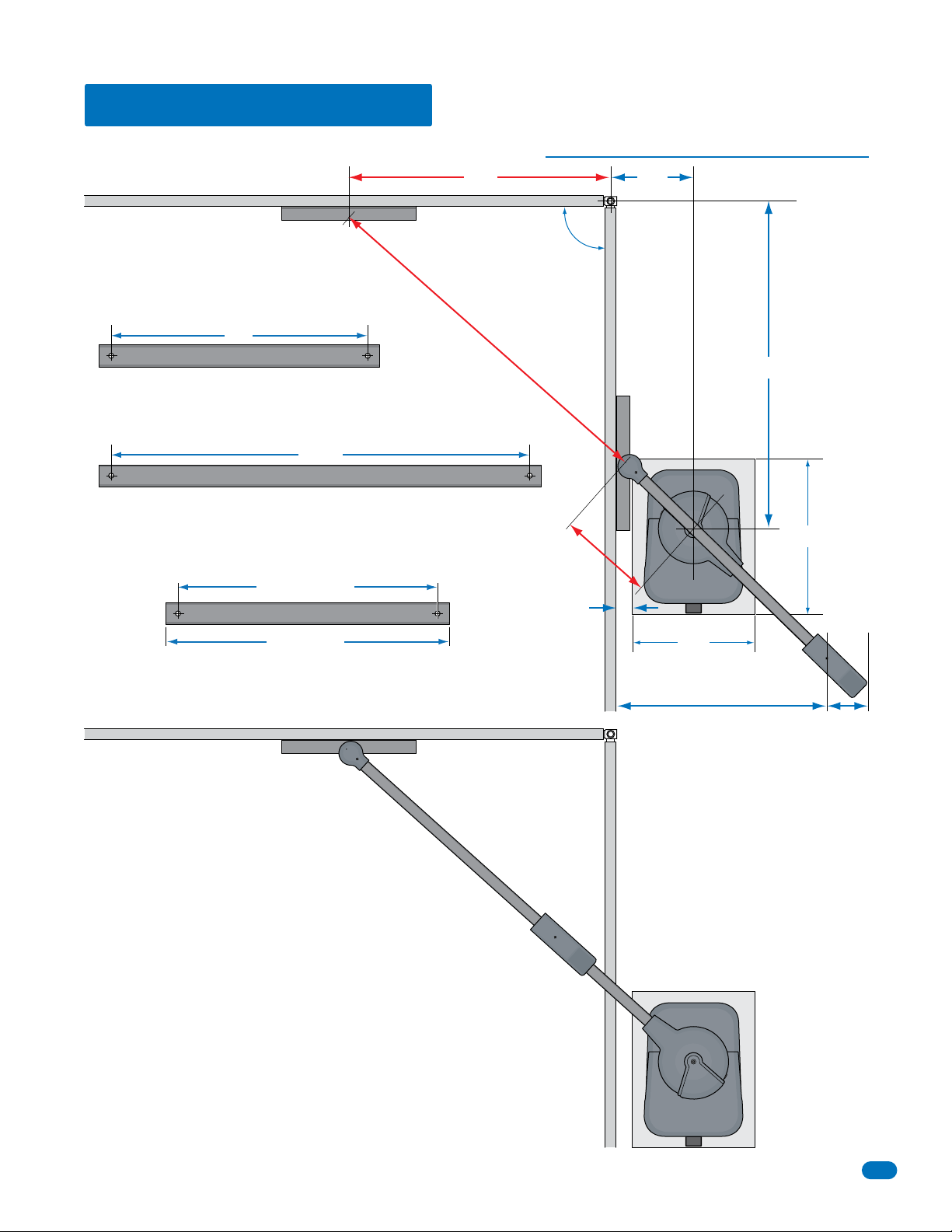
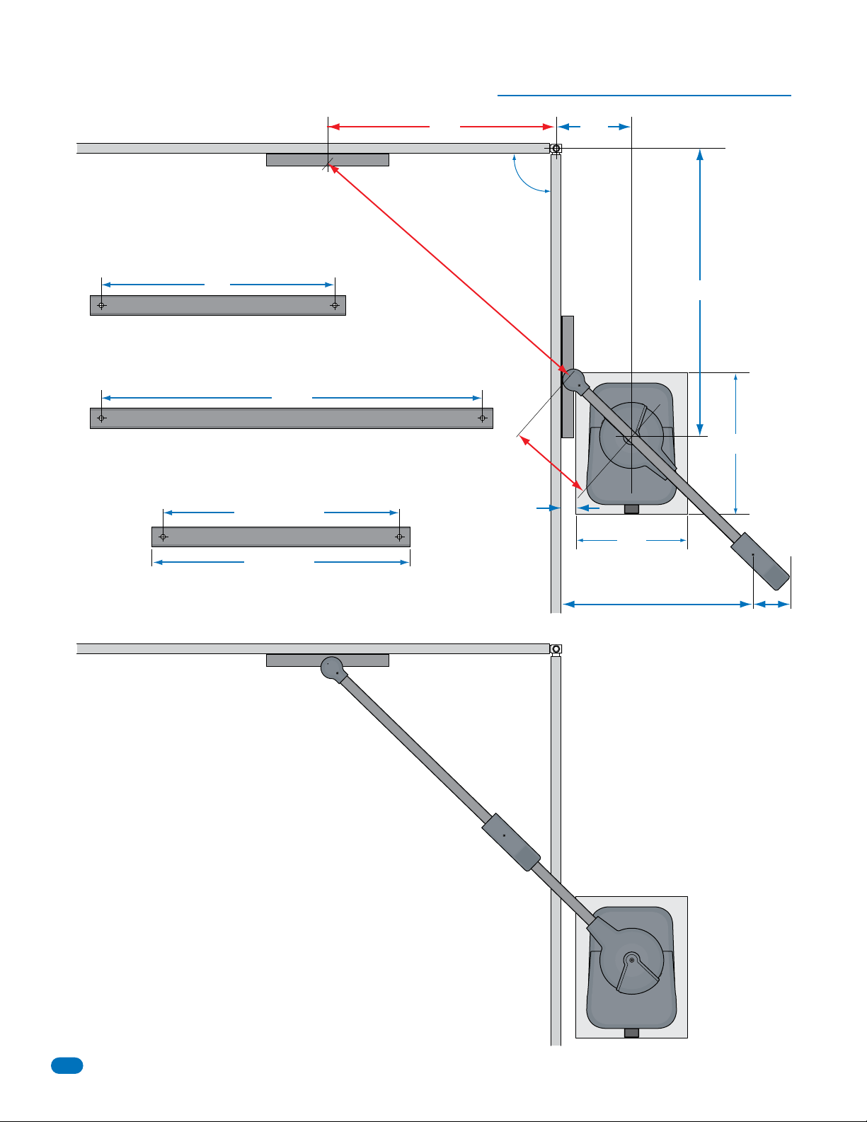
1.3 Installation Layouts
48" Gate Attachment Point - Gates up to 22 Ft.
Closed Gate
48”
Arm Calculations
Drive Arm
67.94” / 2 = 33.97 (round number up) = 34 inches
34”
Drive Arm
Connecting Arm
67.94” + 17.61” - 33.97” = 51.58 (round number down) = 51.5 inches
51.5”
Connecting Arm
Note: Maximum usable connecting arm length is 58.5 inches.
Note: Arm length is measured from center hole to center hole.
“Actual” arm length will be longer.
Measured Length
Arm
67.94”
90°
17.61”
3”
15”
Hinge
Open GateOpen Gate
60”
28”
Closed Gate
Actual Length
Connecting Arm
Arms in Closed Position
Drive Arm
22”
Arms in Open Position
37”
6”
6500-065-J-7-18
9
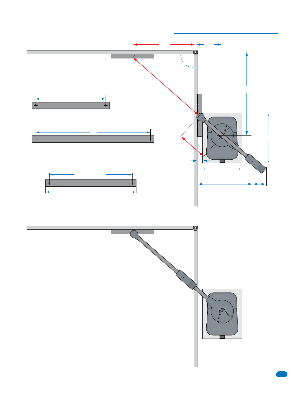
46" Gate Attachment Point - Gates up to 22 Ft.
Closed Gate
46”
Arm Calculations
Drive Arm
67.88” / 2 = 33.94 (round number up) = 34 inches
34”
Drive Arm
Connecting Arm
67.88” + 18.38” - 33.94” = 52.32 (round number down) = 52.25 inches
52.25”
Connecting Arm
Note: Maximum usable connecting arm length is 58.5 inches.
Note: Arm length is measured from center hole to center hole.
“Actual” arm length will be longer.
Measured Length
Arm
Actual Length
67.88”
15”
Hinge
90°
63”
Open GateOpen Gate
28”
18.38”
3”
22”
Arms in Open Position
Closed Gate
Connecting Arm
Arms in Closed Position
Drive Arm
36”
6”
10
6500-065-J-7-18
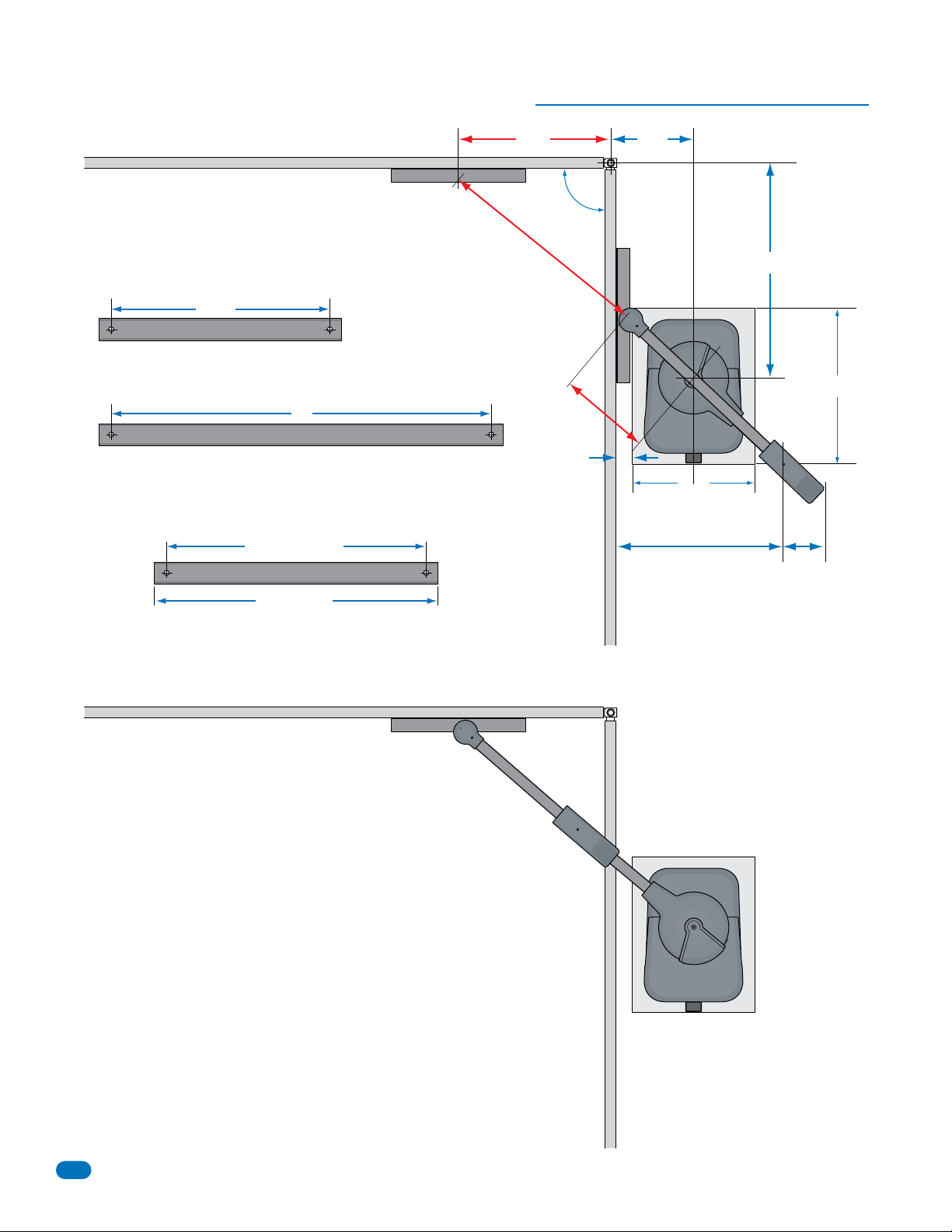
36" Gate Attachment Point - Gates up to 14 Ft.
Closed Gate
Arm Calculations
Drive Arm
50.99” / 2 = 25.495 (round number up) = 25.5 inches
25.5”
Drive Arm
Connecting Arm
50.99” + 17.56” - 25.495” = 43.055 (round number down) = 43 inches
43”
Connecting Arm
Note: Maximum usable connecting arm length is 58.5 inches.
Note: Arm length is measured from center hole to center hole.
“Actual” arm length will be longer.
Measured Length
Arm
Actual Length
50.99”
36”
90°
17.56”
3”
15”
Hinge
22”
Arms in Open Position
31.5”
47.75”
28”
6”
Closed Gate
Open GateOpen Gate
Connecting Arm
Arms in Closed Position
Drive Arm
6500-065-J-7-18
11
28" Gate Attachment Point - Gates up to 8 Ft.
Closed Gate
Arm Calculations
Drive Arm
39.7” / 2 = 19.85 (round number down) = 19.75 inches
19.75”
Drive Arm
Connecting Arm
39.7” + 17.26” - 19.85” = 37.11 (round number down) = 37 inches
37”
Connecting Arm
Note: Maximum usable connecting arm length is 58.5 inches.
Note: Arm length is measured from center hole to center hole.
“Actual” arm length will be longer.
Measured Length
Arm
28”
39.7”
90°
17.26”
3”
15”
Hinge
22”
Arms in Open Position
27.5”
39.25”
28”
6”
Closed Gate
Actual Length
Connecting Arm
Arms in Closed Position
Open GateOpen Gate
Drive Arm
12
6500-065-J-7-18
 Loading...