

Page 1
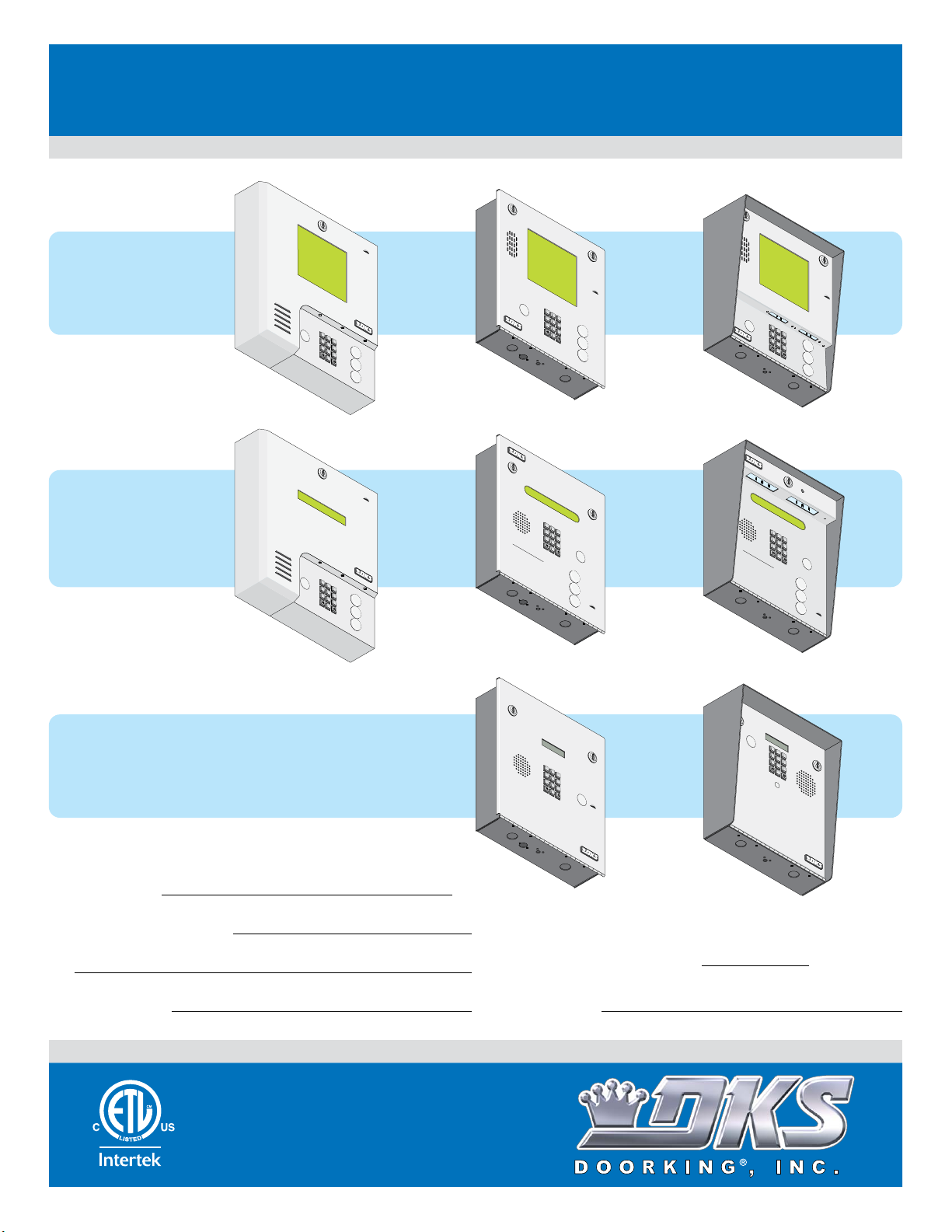
Installation/Owner’s Manual
PC Programmable
7
8
9
4
5
6
1
2
3
0
O
P
ER
W
X
Y
Z
T
U
V
P
Q
R
S
M
N
O
J
KL
G
H
I
D
EF
A
B
C
S
P
7
8
9
4
5
6
1 2
3
0
O
P
E
R
W
X
Y
Z
T
U
V
P
Q
R
S
M
N
O
J
K
L
G
H
I
D
E
F
AB
C
SP
1833
7 8
9
4
5
6
1
2
3
0
O
P
E
R
W
X
Y
Z
T
U
V
P
Q
R
S
M
N
O
J
K
L
G
H
I
D
EF
A
B
C
S
P
7
8
9
4
5
6
1
2
3
0
O
P
E
R
W
X
Y
Z
T
U
V
P
Q
R
S
M
N
O
J
K
L
G
H
I
D
E
F
A
B
C
S
P
7
8
9
4
5
6
1
2
3
0
O
P
E
R
W
X
Y
Z
TU
V
P
Q
R
S
M
N
O
J
K
L
G
H
I
D
E
F
A
B
C
S
P
1837
7
8
9
4
5
6
1
2
3
0
O
P
E
R
W
X
Y
Z
TU
V
P
Q
R
S
M
N
O
J
K
L
G
H
I
D
EF
A
B
C
S
P
7
8
9
4
5
6
1
2
3
0
O
P
E
R
W
X
YZ
T
U
V
PQ
R
S
M
N
O
J
K
L
G
H
I
D
EF
A
B
C
S
P
7
8
9
4
5
6
1
2
3
0
O
P
E
R
W
X
Y
Z
T
U
V
PQ
R
S
M
N
O
J
K
L
G
H
I
D
E
F
A
B
C
S
P
1834
1835
Telephone Entry and Access Control Systems
PC Programmable
PC Programmable
1835-065-E-7-13
1837
1837
Weigand Compatable
1834
1834
1835
1835
Weigand Compatable
Wall Mount
SP
ABC
D
G
EF
H
I
JK
L
PQ
M
NO
RS
TU
V
WXYZ
OPER
1837-089
Wall Mount
SP
AB
C
D
G
EF
HI
JK
L
PQRS
M
N
O
TU
V
W
XY
Z
O
PE
R
1834-089
1835-089
CALL
CALL
Flush Mount
S
P
A
B
C
D
G
E
H
F
I
J
K
L
PQ
M
N
R
O
S
T
U
V
WX
A
Y
Z
O
P
E
R
A
Z
1837-084
CALL
Z
Flush Mount
TEL
EP
HONE EN
T
RY
S
YSTEM
S
P
A
B
C
D
G
E
H
F
I
JK
L
P
M
Q
N
R
O
S
TU
V
OP
WX
ERA
1
.
2.
3
.
A
Z
1834-084
1835-084
YZ
U
T
se “A
O
P
IN
ER
N
G IN
ame
t
o
N
and
S
Z”
am
TR
Bu
e
C
To
s
U
od
t
a
t
C
e
on
re
C
TI
Nu
al
Ke
s
In
O
l
m
, En
to Loc
ypad
Alp
N
b
er
Lin
S
ha
t
on
o
er C
e
b
at
r
HOLD TO
is
D
H
e
Pr
e
is
tic
a
o
B
ng Up. Try
ess
p
de Number
u
a
la
sy
l
E
y
,
Ord
.
“
nter
P
C
re
a
e
ll
ss
o
r
.
”
n
B
“
A
Ope
gai
n.
n
Disp
S
#
u
”
on
CAN
tto
or
n
“Call
.
If
”
la
A
to
y
an
d To
n
e
.
Z
CALL
Surface Mount
S
P
A
B
C
D
G
EF
H
I
J
K
L
P
M
Q
N
R
O
S
T
U
V
A
WX
Y
Z
O
P
E
R
Z
CA
1837-080
LL
Surface Mount
TELEPHONE ENTRY SYS
T
S
P
EM
A
B
C
D
G
E
H
F
I
J
K
L
P
M
Q
N
RS
O
T
O
U
V
P
ERAT
1.
WX
Y
U
Z
se
IN
“A
O
P
N
G
ER
ame
t
I
o
N
N
a
S
Z” Butt
am
n
2.
TR
d
e
C
T
s a
o
U
o
d
C
e
on
re
C
TI
Nu
al
Key
I
s
n
O
l
m
,
t
Alp
o Lo
N
p
be
En
ad
L
S
r
in
ha
t
o
o
er C
c
e
n
b
a
r
i
D
H
et
s B
te
P
HOLD TO SCAN
i
ang U
ode
s
r
i
3.
ca
e
pla
u
s
sy
l
s
E
y
,
O
N
.
“
n
p.
P
r
u
C
te
d
r
mber on
a
e
T
er
r
ll
s
ry
o
s
.
”
Agai
n
“
B
#
Op
u
”
tto
o
e
n.
r
n
n.
“
D
C
If
a
is
l
l”
play
to
A
a
n
d
T
o
n
e
.
Z
CALL
1834-080
1835-080
1833
1833
Weigand Compatable
Date Installed:
Installer/Company Name:
Phone Number:
Leave Manual with Owner
Flush Mount
TEL
EP
HONE
ENTR
Y
SYSTEM
S
P
A
B
C
D
G
E
H
F
I
JK
L
P
M
Q
N
R
O
S
T
U
V
W
X
YZ
O
P
E
R
O
1.
PE
Locate C
RA
2.
P
TI
re
ode
N
s
s
P
G IN
C
re
ode
Number
3.
s
s
Ent
S
“#
Nu
TR
e
”
m
r on To
to
on Direc
ber
U
CT
H
.
ang
If Line is
I
n
O
e
UP
.
to
N
r
S
.
y.
T
r
y
B
usy,
Again.
1833-084
Circuit Board
Serial Number
and Revision Letter:
Copyright 2013 DoorKing, Inc. All rights reserved.
Model Number
Surface Mount
TELEPHONE ENTR
Y S
YSTEM
S
P
A
B
C
D
G
E
H
F
I
JK
L
P
M
Q
N
R
O
S
T
U
V
W
X
Y
Z
O
P
E
R
OPE
1.
Locate
R
2.
ATI
P
r
C
es
ode
N
s
Pr
G INST
C
es
ode
Number
3.
s
Ent
“#”
Num
e
R
r on Ton
to
on
ber
U
CTI
H
D
.
ang
irec
If Line is
O
e
UP
.
to
N
r
S
.
y.
T
r
y
B
Again.
us
y,
1833-080
TM
UL Listed
Copyright 2009 DoorKing, Inc. All rights reserved.
Page 2

Page 3
SPECIFICATIONS
7
8
9
4
5
6
1
2
3
0
O
P
E
R
W
X
Y
Z
T
U
V
P
Q
R
S
M
N
O
J
K
L
G
H
I
D
E
F
A
B
C
S
P
7
8
9
4
5
6
1
2
3
0
OP
ER
W
X
YZ
T
UV
P
Q
R
S
M
N
O
JK
L
G
H
I
DEF
A
B
C
S
P
7
8
9
4
5
6
1
2
3
0
O
P
E
R
WX
YZ
T
U
V
P
Q
R
S
M
N
O
J
K
L
GH
I
D
EF
A
B
C
S
P
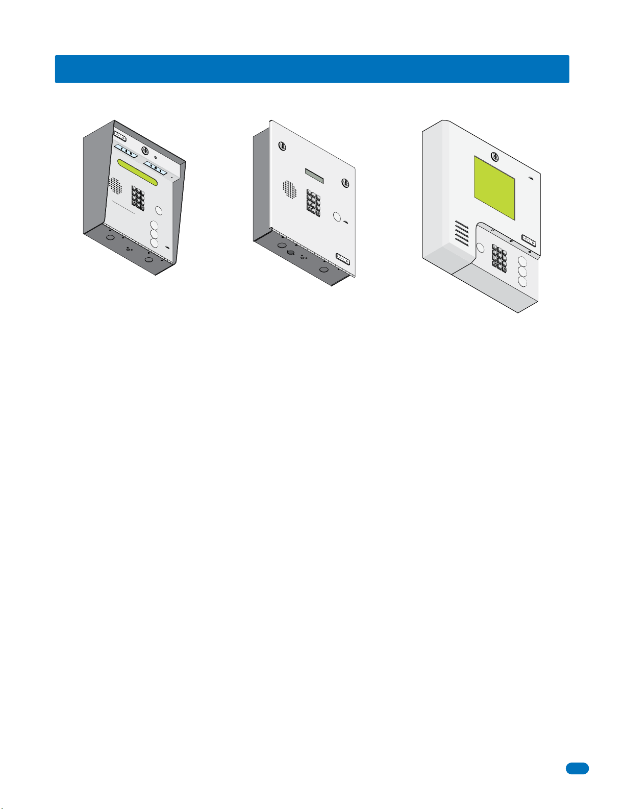
1833, 1834, 1835 and 1837 Telephone Entry Systems, REV C or Higher.
TELEPHONE ENTR
Y SYSTEM
S
P
1
A
B
C
2
DEF
GHI
3
4
JK
L
5
P
MN
QR
O
S
6
7
T
OPERA
UV
8
1.
Use “A to Z” Buttons to Locat
Name and
Na
2
.
T
Keypad or Pr
Line is Bu
Hang
3
.
Ente
Surface Mount
TING
me
s
o Call, Enter Code
a
re In Alph
s
U
p
.
r on
O
INSTRUCTIONS
C
ode
N
ess
y
, Press “#” or “Call”
Tr
y Ag
ai
pen Display and To
WX
YZ
9
OPER
0
umber o
abetic
n
Display
e
HOLD TO SCAN
a
l
O
Numb
.
“C
rd
al
er
l
.
” Button
er on
n.
. If
to
A
ne
.
Z
CALL
Flush Moun
Features
• Can provide service for up to 3000 residents.
• Can store up to 8000 card, transmitter or digital PIN codes (not applicable to 1834).
TELEPH
ON
E ENTR
Y SYSTEM
S
P
1
A
B
C
2
DE
GH
F
I
3
4
JK
L
5
P
M
QR
NO
S
6
7
TUV
8
W
X
Y
Z
9
OP
ER
0
OP
1.
L
E
o
ca
RA
2.
t
Pre
e
TING
C
o
ss C
d
Pre
e
Nu
o
INS
3.
s
d
s “
e
m
E
Nu
n
b
#
T
te
e
”
RUC
r
m
r
t
o
b
o
o
n
e
n
Ha
Di
r.
To
T
If
n
r
IO
n
e
g
L
e.
ct
UP
i
N
n
o
e
ry
S
.
is
.
T
ry
B
u
A
sy
g
a
,
i
n
.
SP
1
A
B
C
2
DE
GHI
F
3
4
J
K
L
5
PQR
M
NO
S
6
7
TU
V
8
A
WX
YZ
9
OP
E
R
0
Z
t
Wall Mount
CALL
• System can be programmed with a PC by modem, RS-232 (wired or wireless (wireless requires 1814-075 adapters),
RS-422 (requires 1508-055 adapters), a LAN or WAN connection (requires 1830-175 TCP/IP kit) or via the internet using
the Internet Modem Server (use of the IM Server is fee based. Visit http://www.doorking.com/IMServer for more
information).
• ONE TOUCH CALLING provides the easiest to use system on the market (does not apply to 1833).
• System keypad will emit DTMF tones after a call is answered allowing the system to be used with auto-attendants,
answering machines, etc.
• Directory codes can be set from 1 to 4 digits in length and can be randomly assigned.
• Transaction buffer stores the last 8000 events and has its own backup power source to retain memory during power
outages.
• View LIVE transactions.
• 31-security levels total (security level 00 always denies entry, security level 01 always admits entry), with 29 programmable
security levels, each with four time zones allows you to control and restrict user access as needed (not applicable to 1834).
• Programmable holiday schedule (not applicable to 1834).
• Facility codes can be enabled or disabled. Store up to 10 different facility codes (not applicable to 1834).
• True Anti-Pass Back feature.
• Up to 255 programmable area codes (Rev E and higher boards only) allow the system to be used in areas requiring
10 and 11-digit dialing.
• Three internal relays allow the system to control a main entry point plus two additional entry points (1834 system has
only 2 relays).
• System can be expanded to control up to 16 entry points in addition to the main entry point. Expansion boards are
required (one for each additional entry point) and are not included with the system. Expansion boards also provide output
for door ajar and forced entry alarms (not applicable to 1834).
• Optional elevator control board(s) can control up to four elevators with each elevator serving up to 64 floors (not applicable
to 1834).
• System will interface with selected models of DKS DoorKing vehicular gate operators to provide gate operator information
and data (requires a Expansion board for each gate operator that is to send data to the system). Not applicable to 1834.
• Available in surface, flush or wall mount styles (1833 available in surface or flush mount only).
DoorKing, Inc. reserves the right to make changes in the products described in this manual without notice and without obligation of DoorKing, Inc. to notify any persons
of any such revisions or changes. Additionally, DoorKing, Inc. makes no representations or warranties with respect to this manual. This manual is copyrighted, all rights
reserved. No portion of this manual may be copied, reproduced, translated, or reduced to any electronic medium without prior written consent from DoorKing, Inc.
1835-065-E-7-13
1
Page 4
TABLE OF CONTENTS
SPECIFICATIONS
Important Notices FCC - United States, DOC - Canada
General Information Installation Guidelines and Safety Information
SECTION 1 - INSTALLATION
1.1 General Installation
1.1.1 Remove Components from Enclosure
1.2.1 Install Enclosure
1.2 Surface Mount Dimensions
1.2.1 Surface Mount Recess Kit Dimensions and Installation
1.3 Flush Mount Dimensions
1.3.1 Flush Mount Kit Dimensions and Installation
1.3.2 Flush Mount Surface Mounting Kit Dimensions and Installation
1.4 Wall Mount Dimensions
1.5 Memory Chip Replacement
1.6 Postal Lock Installation
SECTION 2 - WIRING
2.1 Wiring Guidelines
2.1.1 Power
2.1.2 Wire Runs
2.1.3 Grounding
2.1.4 Surge Suppression
2.1.5 Expansion Boards and Elevator Control
2.1.6 Ferrite Filter
2.2 Terminal Descriptions
2.3 Telephone Entry System Wiring
2.3.1 ALL telephone Entry Systems - No Expansion Boards
2.3.2 Wiring Up to 8 Expansion Boards - 1833, 1835 and 1837 Systems
2.3.3 Wiring 9 - 16 Expansion Boards - 1833, 1835 and 1837 Systems
2.4 PC Connection Options
2.4.1 Phone Modem Connection
2.4.2 Direction Connection using the Circuit Board’s RS-232 Terminal
2.4.3 RS-232 Terminal using RS-422/USB Connection
2.4.4 RS-232 Terminal using Wireless Connection
2.4.5 RS-232 Terminal using TCP/IT Converter LAN Connection
2.4.6 RS-232 Terminal using TCP/IT Converter WAN Connection
2.4.7 DoorKing DKS Internet - Modem Server
SECTION 3 - PROGRAMMING
3.1 General Programming Information
3.1.1 Programming from a PC
3.1.2 Programming from the Telephone Entry System Keypad
3.1.3 System Memory Chip Identification
3.2 Setup Telephone Entry System for PC Programming
3.2.1 Master Code
3.2.2 Number of Area Codes Allowed
3.2.3 Call-Up Operation when Interfacing with DoorKing 1816 or 1820 Systems
3.2.4 Resident Elevator Button Relay Time
3.2.5 “Tone Open” Sound ON or OFF
3.2.6 RS-232 Speed Setting
Required
3.2.7 Switch Input Feature
Programming
System Keypad
3.2.8 Elevator Control Feature
3.2.9 Single or Multiple Systems
Overview for System Keypad Programming
3.3 General Programming using the System Keypad
3.3.1 Relay Strike Time
3.3.2 Talk Time
3.3.3 Tone Open Numbers
3.3.4 Switch Input Relay(s) Activation
3.3.5 Touch-Tone / Rotary-Dial
3.3.6 Rotary-Dial 9 Relay(s) Activation
3.4 Programming Letters, Numbers and Messages
3.4.1 Programming Letters, Numbers from Keypad
3.4.2 Programming the User Message - 1834, 1835 Systems
when NOT using a PC
3.4.3 Programming the Instruction Message - 1834, 1835 Systems
System Keypad Programming
3.4.4 Programming the User Message - 1837 System
3.4.5 Programming the Instruction Message - 1837 System
1
4
5
6
6
7
8
9
10
11
12
13
14
15
16
17
17
17
17
18
18
18
18
19
20
20
21
22
23
23
23
23
24
24
24
24
25
25
25
25
26
26
26
27
27
27
27
28
28
28
28
29
30
30
30
31
31
32
32
33
33
34
35
36
37
2
1835-065-E-7-13
Page 5
TABLE OF CONTENTS
3.5 Programming Phone Numbers and Names
3.5.1 Programming the Directory Code Length
3.5.2 Programming Directory Codes with 7-Digit Phone Number - NO Area Code
3.5.3 Programming Area Codes
3.5.4 Programming Directory Codes with Phone Numbers that use Area Codes
3.5.5 Programming Names - 1834, 1835 and 1837 Systems Only
3.5.6 Deleting Individual Phone Numbers
3.5.7 Delete Names - 1834, 1835 and 1837 Systems Only
3.5.8 Delete Area Codes
3.5.9 Delete phone Numbers - 1834, 1835 and 1837 Systems Only
3.5.10 PBX Line Access Code Programming
3.5.11 Touch-Tone Dial Pause
3.6 Programming Device Codes - 1833, 1835, 1837 Only
3.6.1 Programming Five-Digit Device Codes
3.6.2 Deleting Device Codes
3.6.3 Enabling Facility Codes
3.6.4 Programming Facility Codes
3.7 Programming Four-Digit Entry Codes
3.7.1 Programming Four-Digit Entry Codes
3.7.2 Delete Entry Codes
3.7.3 Entry Code Ranges
3.8 Anti-Pass Back
System Keypad Programming when NOT using a PC
3.8.1 Programming the Anti-Pass Back Mode
3.8.2 Re-Sync All Devices
3.8.3 Re-Sync Individual Devices
3.8.4 Reset Facility Counter
SECTION 4 - ADJUSTMENTS
4.1 Speaker Volume, Microphone and Feedback
4.2 Click Sensitivity - Use for Rotary-Dial Phone ONLY
4.3 LCD Display Contrast - 1834, 1835 and 1837
4.4 Back-Lite Cutoff
4.5 Master Code Switch
4.6 Ring Pin Jumper
4.7 Relay 2 Jumper
4.8 Auto - 1816 Interface Jumper
4.9 HF - HS Jumper
SECTION 5 - SYSTEM OPERATING INSTRUCTIONS
5.1 Guest Instructions
5.2 Resident Instructions
5.2.1 Responding to a Guest Call
5.2.2 Using an Entry Code
5.3 System Administrator
5.3.1 Connecting to the Telephone Entry System from a Remote Location
5.3.2 Expansion Board Override HOLD OPEN Command
5.3.3 Relay Check
5.3.4 Time and Date Check
5.4 Miscellaneous Operating Instructions
5.4.1 Talk Time
5.4.2 Telephone Line Sharing
5.4.3 Connection to a PBX System
5.4.4 Areas with 10-Digit Dialing
SECTION 6 - MAINTENANCE
6.1 Troubleshooting
6.1.1 RS-232 Test
6.1.2 Weigand Test - 1835 and 1837 Systems Only
6.1.3 Elevator Control Board(s) Hardware Test - 1835 and 1837 Systems Only
6.1.4 Elevator Board / Floor Hardware Test - 1835 and 1837 Systems Only
6.1.5 Automatic Hang-up Options - 1834, 1835 and 1837 Systems Only
6.2 Accessories
Wiring Schematics 1833, 1834, 1835 and 1837
SECTION 7 - LOG TABLES
7.1 Programming Information Tables
7.1.1 10 Area Codes
7.1.2 255 Area Codes
7.2 Resident Information
RESIDENT INSTRUCTION SHEET
38
39
39
40
40
40
41
41
42
42
42
42
43
43
43
43
43
44
44
44
44
45
45
45
45
45
46
47
47
47
47
48
48
48
48
48
49
49
50
50
50
51
51
51
51
51
52
52
52
52
52
53
53-54
55
55
55
56
56
57
58-61
62
62
62
63-64
65-66
67
1835-065-E-7-13
3
Page 6

Important Notices
FCC – United States
This equipment has been tested and found to comply with the limits for a class A digital device, pursuant to Part 15 of the FCC
Rules and Regulations. These limits are designed to provide reasonable protection against harmful interference when the
equipment is operated in a commercial environment. This equipment generates, uses, and can radiate radio frequency energy
and, if not installed and used in accordance with the instruction manual, may cause harmful interference to radio communications. Operation of this equipment in a residential area is likely to cause harmful interference in which case the user will be
required to correct the interference at his own expense.
FCC Registration Number: DUF6VT-12874-OT-T
DOC - Canada
The Canadian Department of Communications label identifies certified equipment. This certification means that the equipment
meets certain telecommunications network protective, operational, and safety requirements. The Department does not guarantee the equipment will operate to the users satisfaction.
Before installing this equipment, users should ensure that it is permissible to be connected to the facilities of the local telecommunications company. The equipment must also be installed using an acceptable means of connection. The customer should be
aware that compliance with the above conditions may not prevent degradation of service in some situations.
Repairs to certified equipment should be made by an authorized Canadian maintenance facility designated by the supplier. Any
repairs or alterations made by the user to this equipment, or equipment malfunctions, may give the telecommunications
company cause to request the user to disconnect the equipment.
Users should ensure, for their own protection, that the electrical ground connections of the power utility, telephone lines, and
internal metallic water pipe system, if present, are connected together. This precaution may be particularly important in rural
areas.
CAUTION: Users should not attempt to make such connections themselves, but should contact the appropriate electric inspection authority, or electrician, as appropriate.
DOC Registration Number: 1736 4507 A
Notice:
The Load Number (LN) assigned to each terminal device denotes the percentage of the total load to be connected to a telephone
loop which is used by the device, to prevent overloading. The termination on a loop may consist of any combination of devices
subject only to the requirement that the sum of the load numbers of all the devices does not exceed 100.
Notice:
DoorKing does not provide a power transformer on units sold outside of the United States. Use only transformers that are listed
by a recognized testing laboratory to power the telephone entry system. An Inherently Protected Transformer must be used to
power this device. 1833, 1834 and 1835 systems require a 16.5-volt, 20 VA transformer. The model 1837 requires a 16.5-volt,
40 VA transformer.
Listing:
This product has been tested to and found to be in compliance with the UL 294 Safety Standard by Intertek Testing Services NA
Inc. (a Nationally Recognized Testing Laboratory) and is ETL listed.
4
1835-065-E-7-13
Page 7

General Information
• Prior to beginning the installation of the telephone entry system, we suggest that you become familiar with the
instructions, illustrations, and wiring guidelines in this manual. This will help insure that you installation is performed in
an efficient and professional manner.
• The proper installation of the telephone entry panel is an extremely important and integral part of the overall access
control system. Check all local building ordinances and building codes prior to installing this system. Be sure your
installation is in compliance with local codes.
• When used to control a door or pedestrian gate, try to locate the telephone entry system as near as possible to the entry
point. The unit should be mounted on a rigid wall to prevent excessive shock and vibration from closing doors or gates.
Continuous vibration and shock from slamming doors or spring-loaded pedestrian gates will damage the circuit board.
Under no circumstances should the unit be mounted directly to a moving door or gate.
• ADA mounting requirements for door control (Ref: ICC/ANSI A117.1-2009). The requirements below apply only when
the telephone entry system is being used to control entry through a public door only. If this system is used to control
entry through a vehicular gate or private entrance, the dimensions noted below do not apply.
1. Unobstructed Forward Reach. Where a clear floor or ground space allows only a forward approach to an object
and is unobstructed, mounting height shall be a minimum of 15 inches (381 mm), and a maximum of 48 inches
(1.22 m), above the floor or ground to the operable controls.
2. Obstructed High Forward Reach. If the high forward reach is over an obstruction greater than 20 inches, but
less than 25 inches, mounting height shall be a maximum of 44 inches (1.12 m) above the floor or ground to the
operable controls.
3. Unobstructed Side Reach. Where a clear floor or ground space allows a parallel approach to an object and the
side reach is unobstructed, and the edge of the clear floor space is 10 inches (255 mm) maximum from the object,
mounting height shall be a minimum of 15 inches (380 mm), and a maximum of 48 inches (1.22 m), above the
floor or ground to the operable controls.
4. Obstructed High Side Reach. If the side reach is over an obstruction greater than 10 inches, but less than 24
inches, mounting height shall be a maximum of 46 inches (1.17 m) above the floor or ground to the operable
controls.
• When used to control a vehicular gate with an automatic gate operator, the telephone entry system must be
mounted a minimum of ten (10) feet away from the gate and gate operator, or in such a way that a person cannot
operate the entry system and/or touch the gate or gate operator at the same time.
• Be sure that the system is installed so that it is not directly in the traffic lane. Goose neck mounting post and kiosks
work well for these type systems. When planning where to locate the system, take into consideration traffic lane layouts,
turn around lanes for rejected access, conduit runs, power availability, etc.
• Environmental factors must also be taken into account. Surface mount units are designed for direct outdoor
installations, however it is preferable to protect them from direct exposure to driven rain or snow whenever possible.
Flush mount units must be protected from direct exposure to the elements.
• This telephone entry system contains a number of static sensitive components that can be damaged or destroyed by
static discharges during installation or use. Discharge any static prior to removing the circuit board from the lobby panel
by touching a proper ground device.
• Instruct the end user to read and follow these instructions. Instruct the end user to never let children play with or
operate any access control device. This Owner’s Manual is the property of the end user and must be left with them
when installation is complete.
1835-065-E-7-13
5
Page 8
SECTION 1 - INSTALLATION
Prior to installing the telephone entry system, we suggest that you become familiar with the instructions, illustrations, and
wiring guidelines in this manual. This will help insure that you installation is performed in an efficient and professional manner.
Order your telephone line to be installed at least two weeks prior to the planned telephone entry system installation date.
This will assure that a phone line is available when the unit is installed. The telephone company will require the following
information from you:
Type: Touch Tone, Loop Start
Ringer Equivalence: 0.0 A
Jack Type: RJ11C
FCC Registration (US): DUF6VT-12874-OT-T
DOC (Canada): 1736 4528 A
Electrical Listing: Complies with UL 294 - ETL Listed
Caller ID: You may want to order caller ID blocking from the telephone company for the entry system phone line. Without
caller ID blocking, residents with the proper phone equipment WILL BE ABLE to identify the telephone number that the
telephone entry system is installed on. This may or MAY NOT be desirable.
Call Waiting: Residents may order call waiting from their local telephone company AFTER the system has been installed.
They can avoid missing calls coming from the telephone entry system while they are using their phone (No busy signal).
1.1 General Installation
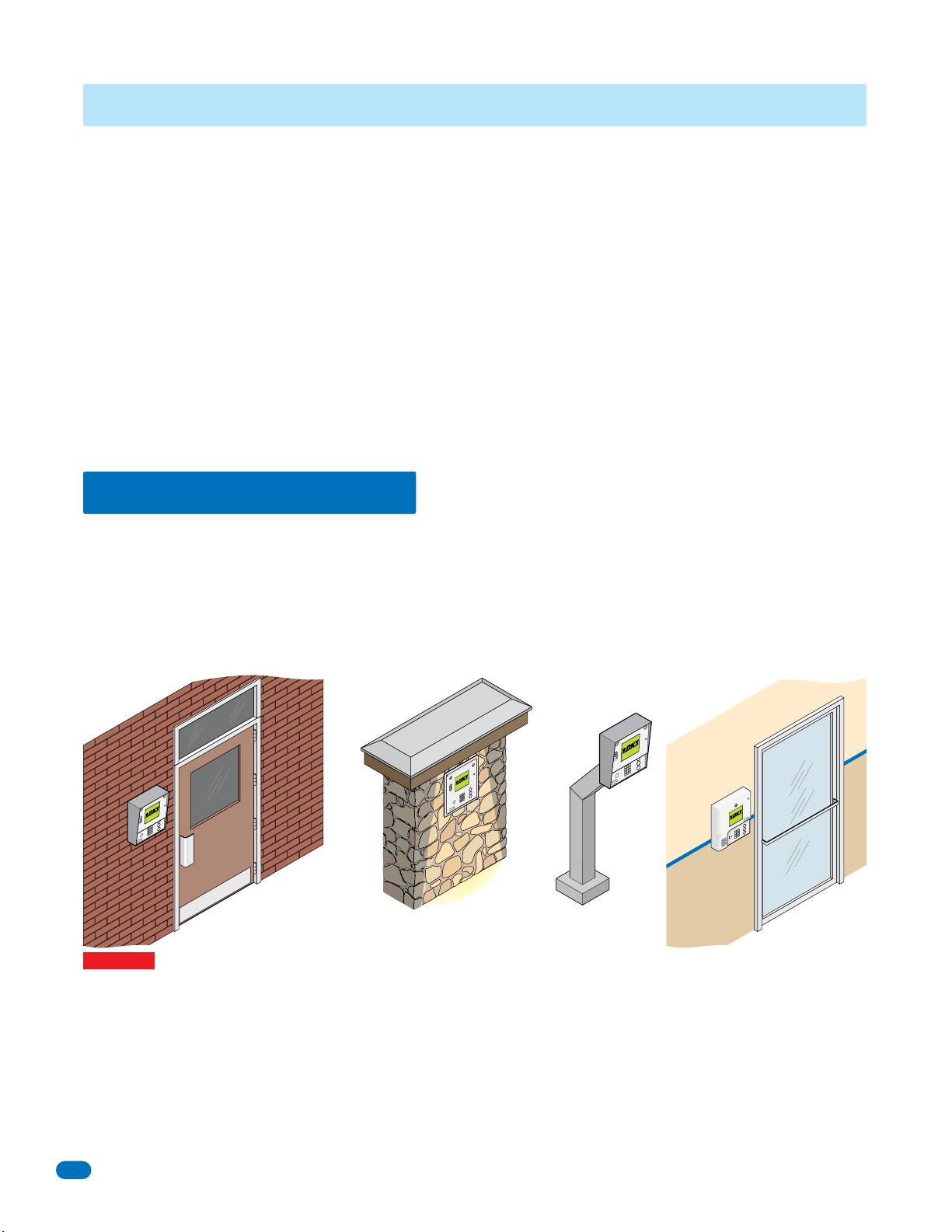
There are 3 different styles of the 1830 telephone entry system (Surface, flush and wall mounts), and many different ways to
mount them (On a wall, in a wall, attached to a architectural style post, kiosk, etc). Specific models will vary a little from the
general installation described in this manual and minor modifications will need to be made depending on which one of the entry
system models has been chosen and where it will be mounted. They will ALL need a telephone line, power and communication
wires run to them in conduit or inside a architectural style post. Feed all of the wires through the back or bottom of the entry
system using the existing knock-outs provided in the enclosures. DO NOT make any new holes in the enclosure to feed wires
through. Keep ALL the entry system’s wires away from any existing high voltage power wires a minimum of 6” to help prevent
any noise and hum pickup in the system’s phone line. The system MUST also be properly grounded to function correctly.
On an Outside Wall On an Inside
WARNING If this telephone entry system is used to control a vehicular gate with an automatic gate operator, the telephone
entry system must be mounted a minimum of ten (10) feet away from the gate and gate operator, or in such a way that the
user cannot come into contact with the gate or gate operator when using this entry system.
The telephone entry system contains a number of static sensitive components that can be damaged or destroyed by static
discharges during installation. Discharge any static prior to removing the circuit board by touching a proper ground device.
GREAT care must be taken after removing the components from the enclosure to protect them throughout the installation.
Carelessness on your part is NOT covered under warranty.
Make sure ALL dirt, metal or wood debris is removed from inside the enclosure after mounting it. A through cleaning of the
enclosure is needed before re-installing the components back into the system and wiring it. Any debris left inside could damage
the control board and cause the telephone entry system to malfunction during operation.
6
In a Lighted-Covered
Kiosk
On a Architectural
Style Post
1835-065-E-7-13
Wall
Page 9
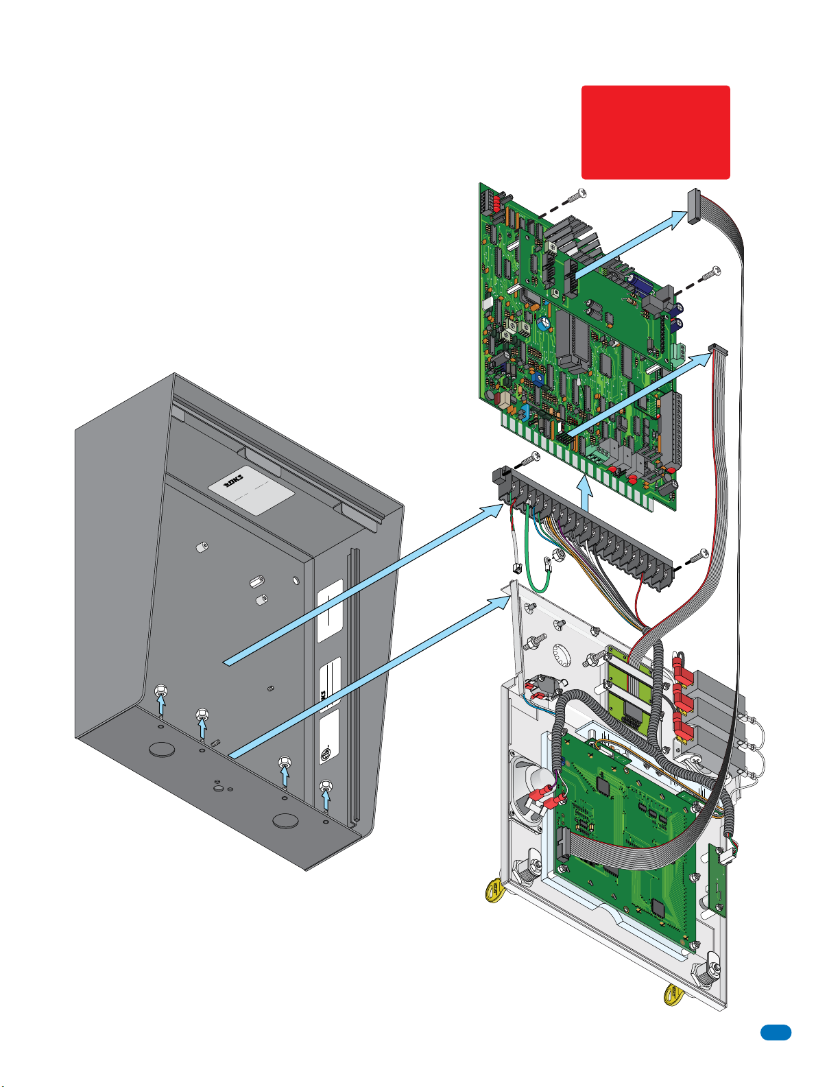
1.1.1 Remove Components from Enclosure
There are 3 different styles of the 1830 telephone entry system - surface, flush and wall
mount. Components in the flush and wall mounts will vary a little from this.
Circuit Board Screw
1. Disconnect the two ribbon cables from the circuit board
(Only one ribbon cable in some models).
2. Remove the two screws from the upper corners of the circuit board.
Discharge any static
BEFORE removing
the circuit board by
touching a proper
ground device.
3. GENTLY remove the circuit board by pulling it out of the main terminal.
4. Remove the two screws from the main terminal and remove the
ground wire locknut.
5. Remove four locknuts from the faceplate hinge (5 for the wall mount).
6. Remove the faceplate, main terminal (still wired), ribbon cables and
the circuit board, store them in a Safe Place until they need to be
re-installed.
Main Terminal Screw
.
e
n
s
NC
in U.S.A.
n
s.
I
r o
o
t
i
e
t
n
,
d
®
te
u
e
l
t
n
o
a
G
u
Da
S
d
N
8
l
. P
e
I
.
4
Mfg.
r
ro
S
u
t
19
n
ct
RK
t No
U.
o
a
g
f
ce
C
en
n
u
n
t
i
i
OO
n
a
ss
S
w
P
D
o
l
ma
l
s
Acce
i
fo
e
ct
h
u
d
f t
o
o
e
r
t
a
re
s p
i
h
mo
.D
1837
T
r
o
ING
A
ND
t No
E
P
S
aten
P
WOOD C
NT
E
E
L
T
A
NG
P
I
R
.,
HE
INC
OT
NG
DOORKI
Surface
Mount
Enclosure
Jack USOC RJ11C or W
Ringer Equiv. 0.0A
DUF6VT-12874-OT-T
F.C.C. Registration #
Complies F.C.C. Part 68
Serial #
Model # 1800 Series
Inglewood, Ca 90301
Faceplate
Hinge
Locknuts
DOORKING
USA
IN
MADE
.
NC
I
,
®
G
N
RKI
PART NUMBER REV SERIAL NO.
DOO
PH
ON
E
DOORKING 1892-010
C
G
N
D
PSW
BA
CKLIT
CUT
E
OFF
S
IN
GLE
LINE
D
IS
PLAY
CONTRAST
MI
C
C
O
M
SPK
Ground
Wire
8 LINE
DISPLAY
R
IMD
5
V
D
C
Main Terminal
I
MC
Z
A
Ribbon
Cable
Ribbon
Cable
DO
O
1491
RK
I
N
-
010
G
2
C
2
R
Y
1
C
N
C
1
N
O1
BAT
1
6AC
1
6AC
1835-065-E-7-13
OUTDOOR USE / WET
SYSTEM UNITS
ACCESS CONTROL
CONFORMS TO UL STD 294
T
S
TRA
N
O
C
Faceplate
7
Page 10
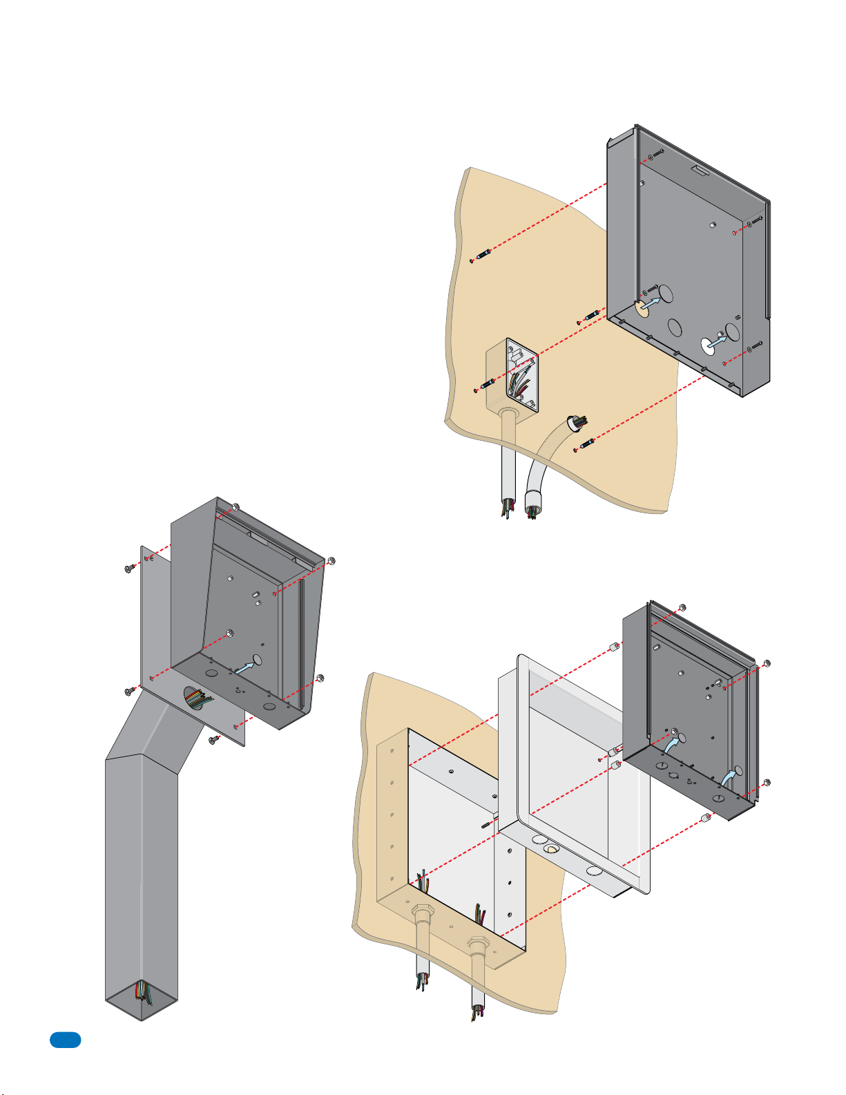
1.1.2 Install Enclosure
There are 3 different styles of the 1830 telephone entry system surface, flush and wall mount. The illustrations below show
typical installations but specific installations can vary from this.
1. Mount the enclosure using the mounting holes provided
in the corners (see sections 1.2, 1.3 and 1.4 for your
chosen model dimensions including kit installations). Be
sure that mounting screws (Not supplied) do not protrude
into the enclosure where they could cause a short on the
back of the circuit board. Make any necessary conduit
connections through the back or bottom of the enclosure
using the existing conduit knock-outs. DO NOT make any
new conduit holes in the enclosure.
2. Route all wiring through conduit or architectural post
(not supplied) into enclosure.
3. Clean out the enclosure. Make sure that all dirt, metal
and/or wood debris is removed.
4. Re-install components back into the enclosure (Reverse
section 1.1.1 steps on previous page). Use the wiring
schematics in the back of this manual to help re-install the
components if necessary. DO NOT apply any power at this
time.
Mount ON a Surface
(See sections 1.2, 1.3.2 and 1.4).
Wall
Use appropriate
hardware to secure
enclosure to the wall
(not supplied).
M
ou
nting
S
Wall Mou
Enclosure
Knock-
crew
s
(Not
supplied)
Mounting Hole
nt
ou
ts
Mount to an
Architectural
Post
Mounting H
o
rface Mount
Enclosure
Knock-o
le
ut
Su
Use hardware supplied with
architectural post to secure
enclosure to post.
Conduit run
to junction box
Examples of conduit runs that may be used, depending on how you choose to run the wiring.
Some installations will allow the conduit to be run outside the wall and connect to the bottom
of the enclosure but this is generally NOT recommended.
Conduit
sweep run
Plastic Spacer
Locknut
Mount IN a Surface
(See sections 1.2.1 and 1.3.1).
Wall
Mounting
(Not s
Rough-In
Box
Screws
upplied)
T
rim
Ring
Flush Mount
Enclosure
Knock-out
s
Run all wires
inside post.
8
1835-065-E-7-13
Page 11
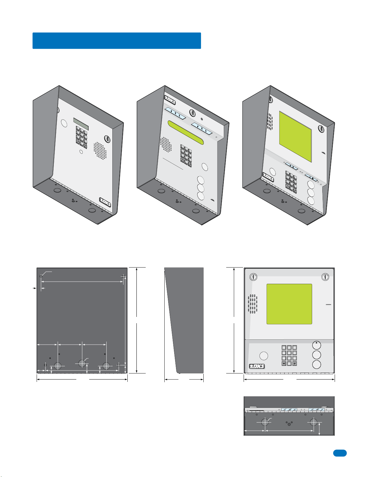
1.2 Surface Mount Dimensions
9
6
3
0
OPER
WXYZ
TUV
PQRS
MNO
JKL
GHI
DEF
ABCSPSP
7
8
9
4
5
6
1
2
3
0
OP
E
R
W
X
Y
Z
T
U
V
P
Q
R
S
M
N
O
J
K
L
G
H
I
D
E
F
A
B
C
S
P
7
8
9
4
5
6
1
2
3
0
O
P
E
R
W
X
Y
Z
T
U
V
P
Q
R
S
M
N
O
J
K
L
G
H
I
D
E
F
A
B
C
S
P
7
8
9
4
5
6
1
2
3
0
O
P
E
R
W
X
Y
Z
T
U
V
P
Q
R
S
M
N
O
J
K
L
G
H
I
D
E
F
A
B
C
S
P
Surface mount units can be mounted directly to a wall, pilaster, post mounted using a DoorKing architectural style mounting
post (P/N 1200-037 and 1200-038) or recessed in a wall (see next page) with the surface mount recess kit (P/N 1803-150). Be
sure the unit is mounted securely and is not subject to vibration from closing doors or gates.
T
ELEPHONE ENTR
Y S
YST
E
M
SP
1
ABC
2
D
G
EF
H
OP
1.
L
ocate
2.
Press C
Press “#”
3.
E
nte
1833
I
3
4
JK
L
5
PQRS
MN
O
6
7
T
U
V
8
W
X
Y
Z
9
O
PE
R
0
E
RAT
Cod
IN
G
e
o
Nu
INSTRUCTIONS
de
mb
N
er
umber
r
to
on
on
H
D
. If
To
a
irecto
ng
n
L
e
UP
ine
.
ry
.
is
.
Try
Busy
Agai
,
n
.
TELEPH
ONE ENTRY SYSTEM
SP
1
ABC
2
D
G
EF
HI
3
4
JK
L
5
PQ
MN
RS
O
6
7
sy
Tr
Z
”
C
ode
P
re
, Pr
y Ag
INST
B
u
tt
o
Num
Al
ber on Display
ph
abe
ode Nu
s
s
“Call” Button. If
ess
“#
ain
.
Di
spla
RUCTIONS
n
s
to
t
i
cal Or
”
o
r
y
a
T
U
V
8
WXYZ
9
OPER
0
L
o
ca
te
.
d
m
er
ber on
.
“
C
a
ll” to
nd
To
n
e.
OPERA
1
.
Us
TING
e
“
Nam
A t
o
e and
Names are In
2.
T
o
Call, Enter C
Keypad or
L
ine
is Bu
Hang Up.
3
.
E
nt
er
o
n
Open
1834, 1835
HOLD TO
A
Z
CAL
SCAN
SP
1
ABC
2
D
G
EF
H
I
3
4
J
KL
5
PQRS
M
N
O
6
7
T
U
V
8
O
PE
0
L
1837
A
W
XYZ
9
R
Z
CALL
25” Dia. Mounting Hole
.5”
2.625” 3”
.875”
1.125”
9”
10.125”
3”
.875” Dia
.875”
1.25”
Side ViewBack View Front View
13” 13”
10.875”
1”
4.75”
2.625”
GHI
PQRS
.875” Dia
ABC
11223
JKL
44556
TUV
77889
OPER
0
11.25”11.25”
6”
DEF
MNO
WXYZ
A
Z
CALL
1.625”
1835-065-E-7-13
Bottom View
9
Page 12
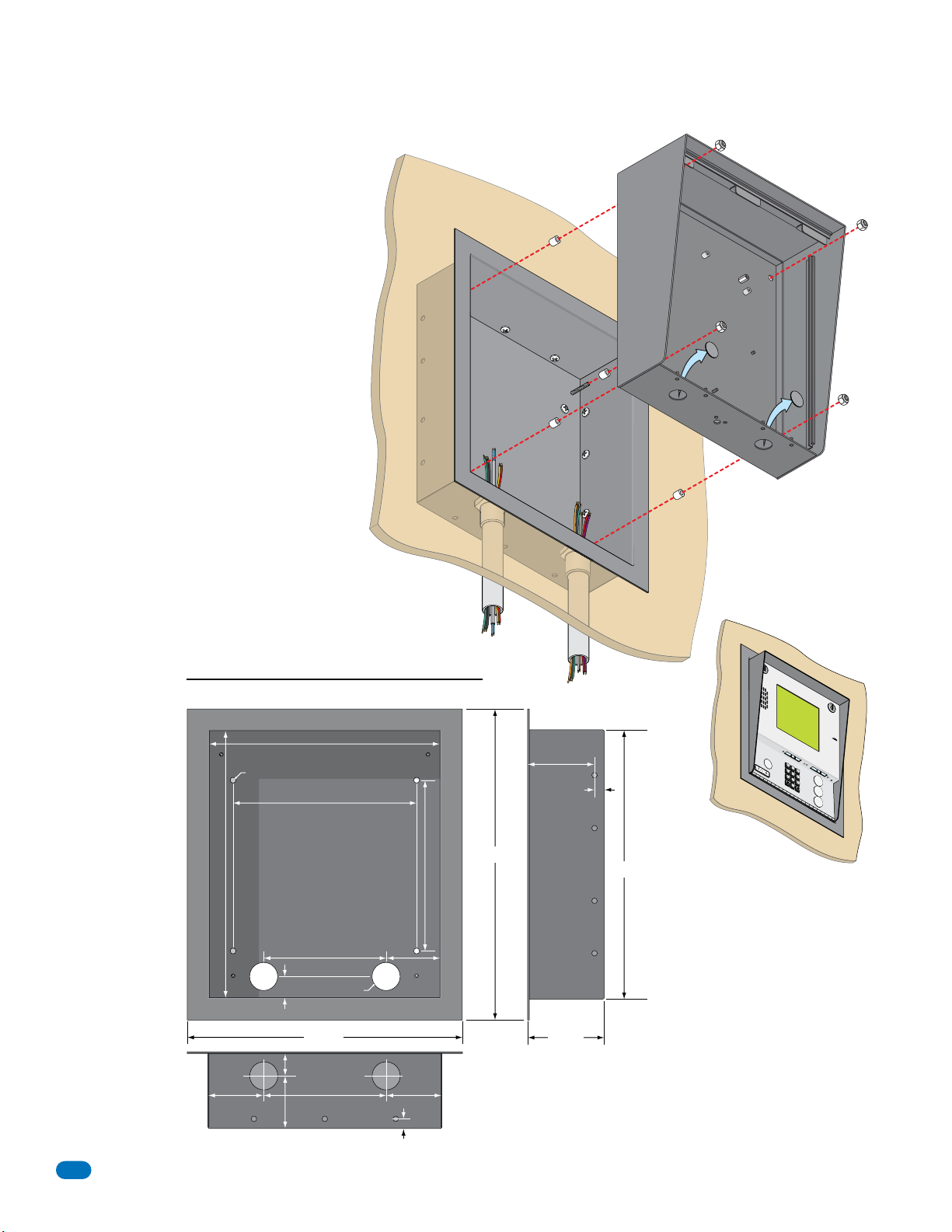
1.2.1 Surface Mount Recess Kit Dimensions and Installation
7
8
9
4
5
6
1
2
3
0
O
P
E
R
W
X
Y
Z
T
U
V
P
Q
R
S
M
N
O
J
K
L
G
H
I
D
E
F
A
B
C
S
P
Surface mount units can be recessed into a
wall or pilaster by using the optional surface
mount recess kit (P/N 1803-150). This allows
for a recessed telephone entry system to
have a lighted keypad (except for the 1833)
which the flush mount units DO NOT have.
The recess box gets installed in the wall. Use
appropriate hardware (not included) to
secure the box in the wall. Run all necessary
conduit (not included) to the recess box.
Slide the enclosure in the recess box and
secure it with the hardware included in the
kit. Be sure the unit is mounted securely and
is not subject to vibration from closing doors
or gates.
Mount In a Surface
Wall
Plastic Spacer
Mounting Screws (Not supplied)
Recess
Box
Locknut
Surface Mount
Enclosure
Knock-outs
Recess Box
Front View
11.25”
Threaded Stud
25” Dia. Mounting Hole
9”
8.5”
15.25”
13.25”
1”
6”
1.375” Dia.
2.625”
13.375”
1.125”
2.625”
6”
2.5”
2.625”
.4”
Bottom View
10
Side View
3.2”
.4”
Mounting
Holes
.25” Dia.
3.625”
13.25”
S
P
1
A
B
C
2
D
G
EF
H
I
3
4
J
K
L
5
P
M
Q
N
R
O
S
6
7
T
U
V
8
A
W
X
YZ
9
O
P
E
R
0
Z
CA
L
L
1835-065-E-7-13
Page 13
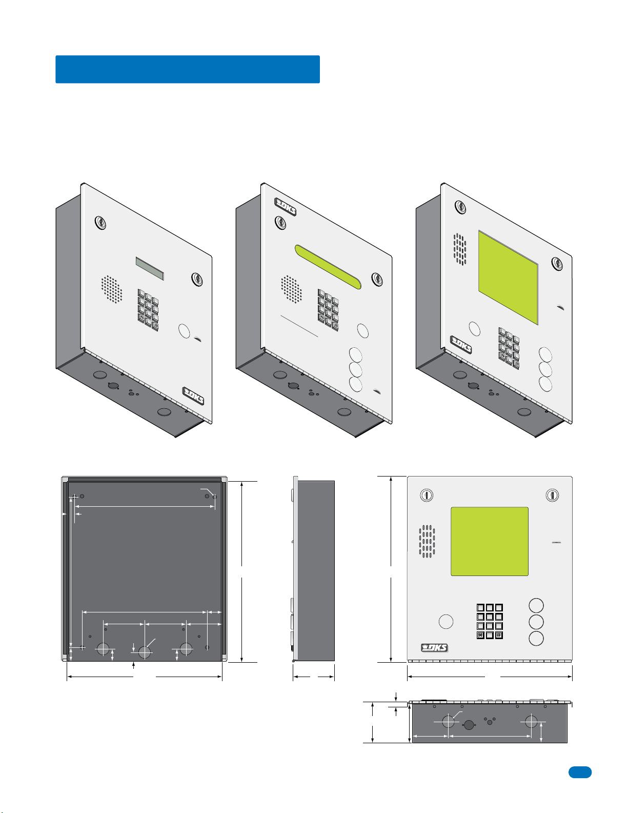
1.3 Flush Mount Dimensions
9
6
3
0
OPER
WXYZ
TUV
PQRS
MNO
JKL
GHI
DEF
ABCSPSP
7
8
9
4
5
6
1
2
3
0
OP
E
R
WX
Y
Z
TU
V
P
QR
S
MN
O
J
KL
GH
I
DE
F
A
B
C
SP
7
8
9
4
5
6
1
2
3
0
OP
E
R
WXY
Z
T
UV
P
QR
S
MN
O
J
K
L
GH
I
DE
F
A
B
C
SP
7
8
9
4
5
6
1
2
3
0
OPER
WXY
Z
T
UV
P
QRS
M
NO
J
K
L
GH
I
DE
F
A
B
C
SP
Flush mount units are installed into a wall with a flush mount kit P/N 1814-165 (stainless) or 1814-166 (gold). Flush mount kits
are NOT INCLUDED with the flush mount entry system (See next page for flush mount kit dimensions). The flush mount units
may also be installed on the surface of a wall with a surface mounting kit if desired P/N 1814-152 (silver only). Flush mount
surface mounting kits are NOT INCLUDED with the flush mount entry system (See page 13 for flush mount surface mounting kit
dimensions). Flush mount units are not designed for direct exposure to the weather. They can be mounted outdoors in an
area protected from direct exposure to the weather, such as a lighted-covered kiosk for example. Be sure the unit is mounted
securely and is not subject to vibration from closing doors or gates.
10.875”
.5”
1833
TELEPHONE ENTR
Y SYSTEM
S
P
1
ABC
2
DEF
GH
I
3
4
JKL
5
PQRS
MN
O
6
7
TUV
8
WXYZ
9
OPER
0
OPER
1.
Locate Code
2.
AT
Press Code Numbe
ING INSTRUCTIONS
Press
Number on Directo
3.
Enter on
“
#” to Hang
r.
To
If Line is Busy,
ne
U
.
P.
ry
.
Try Again.
25” Dia. Mounting Hole
10.125”
TELEPHO
NE ENTR
Y SYSTEM
SP
1
A
B
C
2
DE
GH
F
I
3
4
J
K
L
5
P
M
QR
NO
S
6
7
OPERAT
1.
Use “A to Z” Buttons to Locate
ING INSTRUCTIONS
Name and Code Number on Display.
Names are In Alphabetical Orde
2.
To Call, Enter Code Number on
Keypad or Press “Call” Button. If
Line is Busy,
Hang Up. Tr
3.
Enter on Open Display and To
Press “#” or “Call” to
y Again.
1834, 1835
TUV
8
WX
Y
Z
9
OPER
0
HO
L
D
T
r.
ne.
O SCAN
A
Z
CALL
Side ViewBack View Front View
13.5”13”
1837
S
P
1
A
B
C
2
DEF
GHI
3
4
J
K
L
5
P
MNO
QR
S
6
7
T
UV
8
WX
A
YZ
9
OPER
0
Z
CALL
1”
1835-065-E-7-13
.875”
3”
.5”
11.25”
9”
.875” Dia
.875”
DEF
1.125”
2.625”
3”
3”
.25”
ABC
11223
JKL
GHI
44556
TUV
PQRS
77889
OPER
0
12”
MNO
WXYZ
A
Z
CALL
.875” Dia
3”
2.75”
2.625”
6”
1.5”
Bottom View
11
Page 14
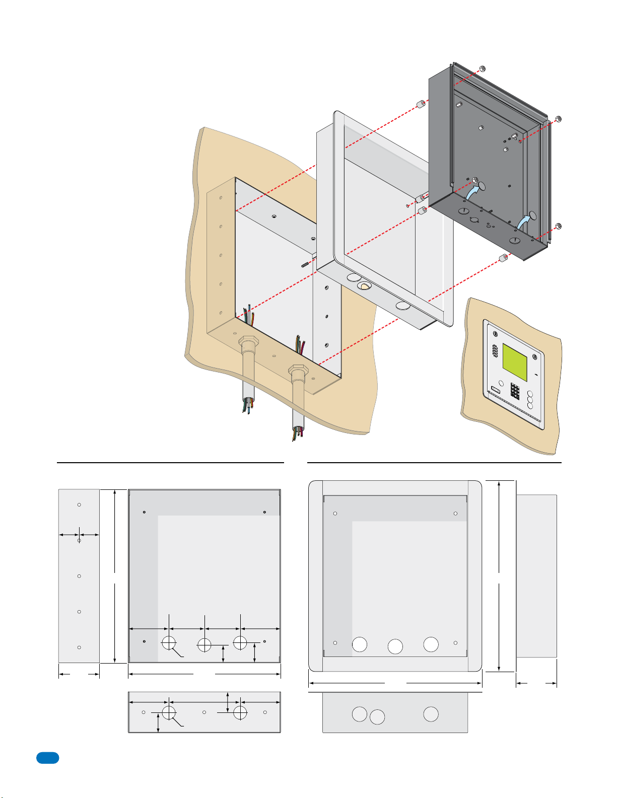
1.3.1 Flush Mount Kit Dimensions and Installation
7
8
9
4
5
6
1
2
3
0
O
P
E
R
W
X
Y
Z
T
U
V
P
Q
R
S
M
N
O
J
K
L
G
H
I
D
E
F
A
B
C
S
P
The flush mount installation kit
has two parts; the rough-in box
and the trim ring. The rough-in
box is installed in the wall first.
Use appropriate hardware (not
included) to secure the box in the
wall. Run all necessary conduit
(not included) to rough-in box.
Slide the trim ring into the
rough-in box. Slide the enclosure
in the trim ring and secure them
all together with the hardware
included in the kit. Be sure the
unit is mounted securely and is
not subject to vibration from
closing doors or gates. See
previous page for flush mount
enclosure dimensions.
Mount In a Surface
Wall
Mounting Screws
(Not supplied)
Rough-In
Box
Plastic Spacer
Trim
Ring
Locknut
Flush Moun
Enclosure
t
Knock-outs
Side View
1.74” 1.71”
Mounting
Holes
.25” Dia.
3.45”
12
Rough-In Box Trim Ring
Front View
Threaded Stud
14.6” 16”
1.5”
3.4”
1.685”
Mounting
Hole
3.4”
3”
3”
1.125” Dia
12.8”
3.4” 3.4”
1.74”
6”
1.8”
1.125” Dia
Front View
Hole for Threaded Stud
14.7”
Bottom ViewBottom View
S
P
1
A
B
C
2
DE
G
H
F
I
3
4
J
K
L
5
P
M
Q
N
R
O
S
6
7
T
U
V
8
W
X
A
Y
Z
9
OP
E
R
0
Z
C
A
LL
Side View
3.45”
1835-065-E-7-13
Page 15
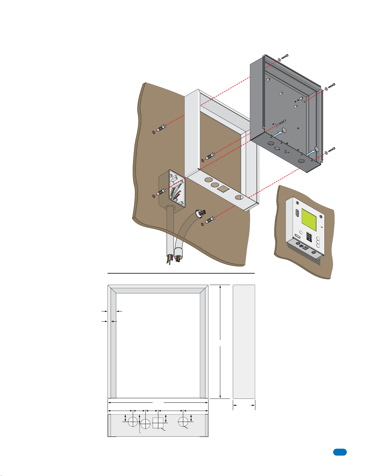
1.3.2 Flush Mount Surface Mounting Kit Dimensions and Installation
7
8
9
4
5
6
1
2
3
0
O
P
E
R
W
X
Y
Z
T
U
V
P
Q
R
S
M
N
O
J
K
L
G
H
I
D
E
F
A
B
C
S
P
Flush mount unit (See page 11 for flush
mount enclosure dimensions) can be
mounted ON a wall or pilaster and NOT IN
the wall by using the optional flush mount
surface mounting kit (P/N 1814-172). This
is useful when cutting a large hole into a
wall or pilaster would be very difficult
(marble or granite for example) .The flush
mount surface mounting kit is a trim ring
that fits around the flush mount enclosure. The enclosure and trim ring get
installed directly on the wall using
appropriate hardware (not included) after
running all necessary conduit to the
enclosure. Be sure the unit is mounted
securely and is not subject to vibration
from closing doors or gates.
Examples of some
small holes in the
wall that may be
needed, depending
on how you choose
to run the wiring.
to junction box
Trim Ring
Mount On a Surface
Wall
Trim Ring
Conduit run
Conduit
sweep
run
Mounting Screws
(Not supplied
)
Flush Mount
Enclosure
Knock-outs
S
P
1
A
B
C
2
D
G
E
H
F
I
3
4
J
K
L
5
P
M
Q
N
R
O
S
6
7
T
U
V
8
W
X
A
Y
Z
9
O
P
E
R
0
Z
C
A
LL
Side ViewFront View
1835-065-E-7-13
.375”
.875”
1”
12”
1.5”
1.5”3” 3” 3”
1.125”
1.125” Sq
Bottom View
13.5”
2.625”
1”
.875”
1.125” Dia
13
Page 16
1.4 Wall Mount Dimensions
9
6
3
0
OPER
WXYZ
TUV
PQRS
MNO
JKL
GHI
DEF
ABCSPSP
7
8
9
4
5
6
1
2
3
0
O
P
E
R
W
X
Y
Z
T
U
V
P
Q
R
S
M
N
O
J
K
L
G
H
I
D
E
F
A
BC
SP
7
8
9
4
5
6
1
2
3
0
O
P
E
R
W
X
Y
Z
T
U
V
P
Q
R
S
M
N
O
J
K
L
G
H
I
D
E
F
A
B
C
S
P
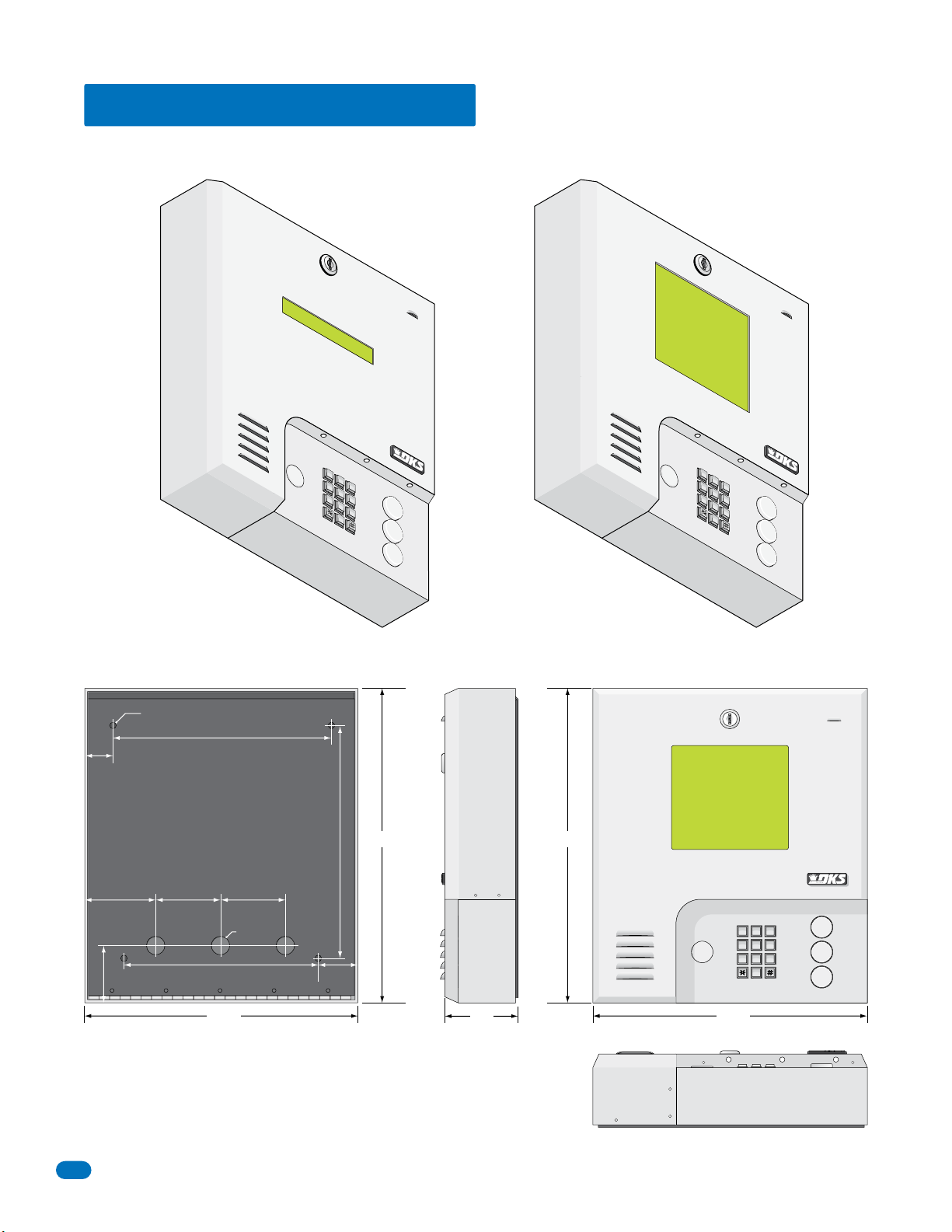
Wall mount units are designed to be mounted directly onto a wall without the need of cutting a large hole as is necessary with
flush mount units. Be sure the unit is mounted securely and is not subject to vibration from closing doors or gates.
25” Dia. Mounting Hole
10.125”
1.5”
3.625” 3” 3”
S
P
1
GH
I
4
P
Q
R
S
7
1834, 1835
AB
2
JKL
5
T
U
8
O
P
E
0
10.875”
S
P
1
A
B
C
D
E
F
3
M
N
O
6
V
A
WXY
Z
9
R
Z
CALL
1837
C
2
DEF
GH
I
3
4
J
K
L
5
PQ
MN
R
O
S
6
7
T
U
V
8
O
P
ER
0
A
WXYZ
9
Z
CALL
Side ViewBack View Front View
15”15”
DEF
2.75”
9”
.875” Dia
2.125”
3.5”
ABC
11223
MNO
JKL
GHI
44556
WXYZ
TUV
PQRS
77889
OPER
0
13.25”13.25”
A
Z
CALL
Bottom View
14
1835-065-E-7-13
Page 17
1.5 Memory Chip Replacement
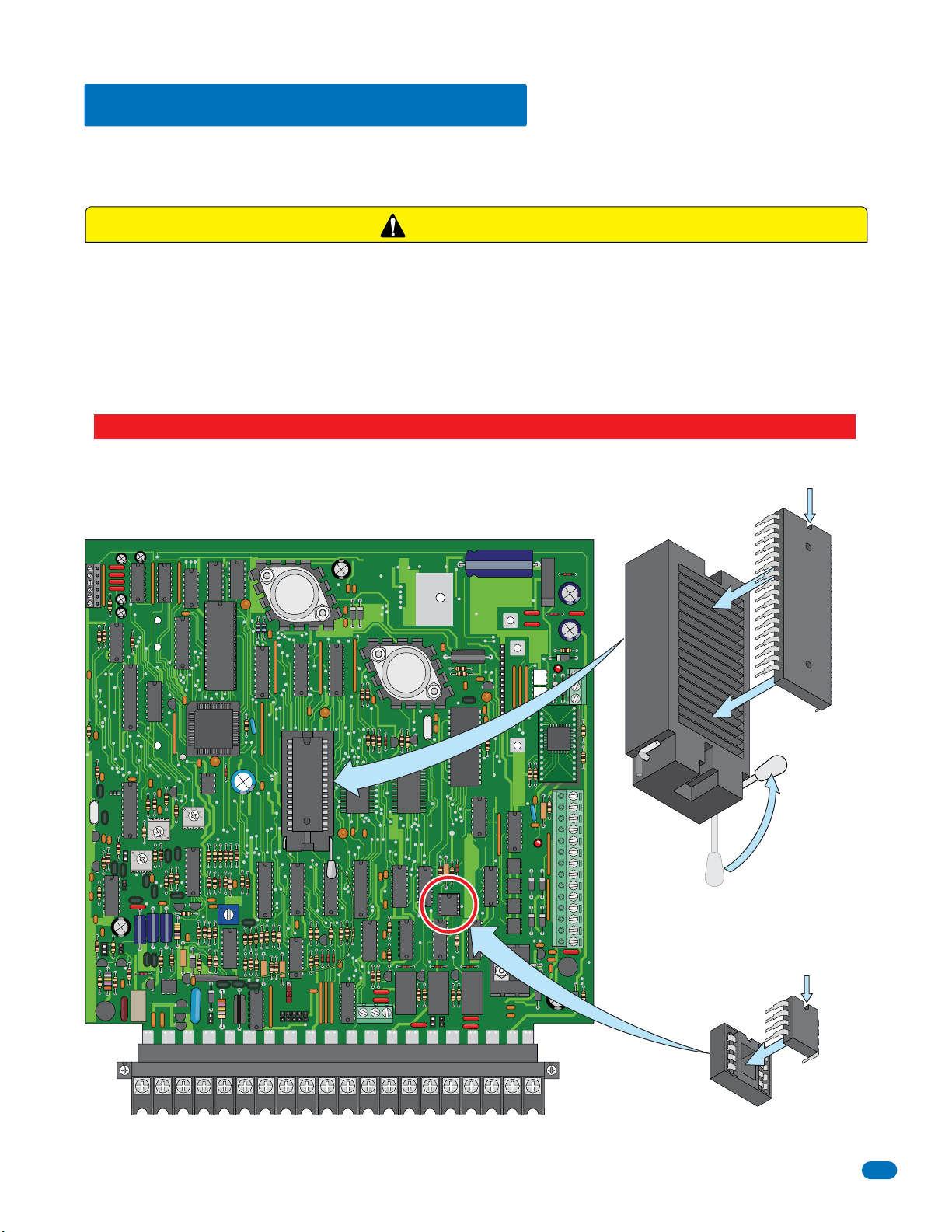
The telephone entry system is shipped with the memory chips already installed in the unit. However, if you need to
replace the memory chips (to match an older unit, for example), follow the instructions below. See 3.1.3 Memory Chip Identification for information about the memory chips in your specific telephone entry system.
CAUTION
Power MUST be OFF to the Circuit Board!!
DO NOT install the memory chips with power to the telephone entry system turned ON. Attempting to install the memory
chips with power on will irrevocably damage the chips. Memory chips are a static sensitive component. Discharge any static
electricity from your hands by touching a proper ground device before touching the control board. Handle the memory chips
with care, the pins bend easily.
DO NOT install the memory chips UPSIDE DOWN. this will cause permanent damage to the chips. Be sure that the memory
chips are seated correctly in the sockets.
Discharge any static electricity from your hands by touching a proper ground device before installing chips!
Dimple MUST be at
the top of the chip!
1830 Series Circuit Board Memory Chip Locations
RS 232
FEED
BACK
321
ELEVATOR
1
2
3
Release
MIC
VOL
321
321
SPK
VOL
Locked
CLK
SEN
12345 67891011121314
Dimple MUST be at
the top of the chip!
ON
MASTER
CODE
OFF
KEYPAD
NO
RING
NC C
NO
NC
16AC16ACBAT1NO1NC1C2RY2CAZIMC5VDCIMDSPKRCOMMICPSWCGNDPHONE
Press Fit
Be Careful!
1835-065-E-7-13
15
Page 18
1.6 Postal Lock Installation
7
8
9
4
5
6
1
2
3
0
O
P
ER
W
X
Y
Z
T
U
V
P
Q
R
S
M
N
O
J
K
L
G
H
I
D
EF
A
B
C
SP
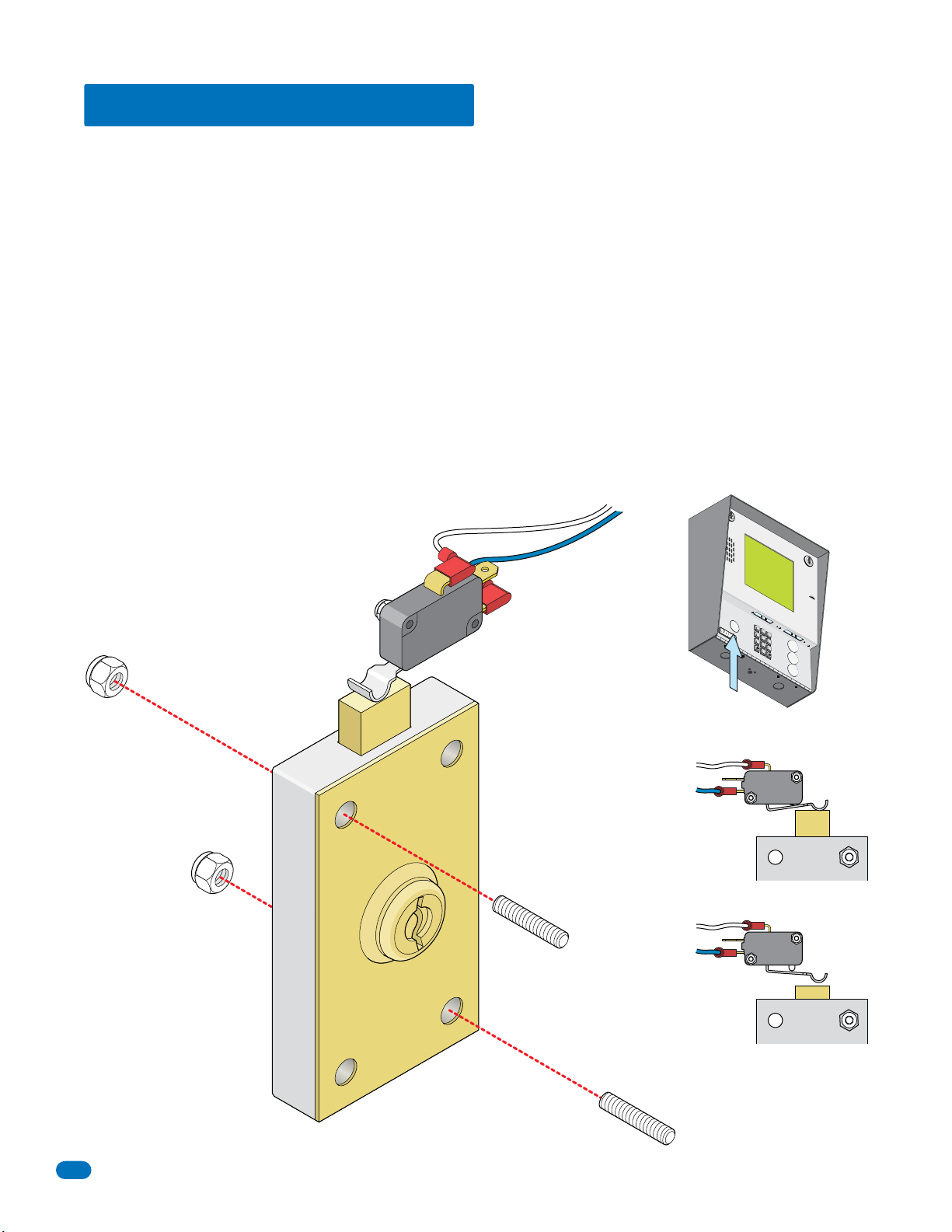
At some locations, such as gated communities, it will be necessary to provide access to the mail carrier so that they can
deliver the mail. Mail carrier access will be provided by the installation of an Arrow Postal Lock. This is the same lock that the
Post Office uses for gang mailboxes. These locks are not available to the public. The installer or the building owner/manager
will have to call the Post Office and arrange for the installation of this lock into the telephone entry system. All DoorKing
commercial telephone entry systems are designed to accept installation of the postal lock.
Prior to installation of the postal lock, be sure power to the telephone entry system is turned OFF.
1. Remove the hole plug on the faceplate of the telephone entry system.
2. Cut the wire tie wrapped around the switch ONLY when installing postal lock.
3. Remove the two hex nuts from the postal lock-mounting studs. Mount postal lock on the studs and secure with the hex nuts.
When the lock is installed, the pawl of the lock, in the extended position is depressing the switch. When the mail carrier inserts
his key and turns the postal lock, the pawl is withdrawn into the lock and the switch will activate the relay for the programmed
strike time, that has been programmed for this feature.
Factory default settings for the Postal Lock Switch: After the key has been turned, Relay 1 will activate (section 3.3.4) for One
(1) second of strike time (section 3.3.1). The switch input feature (section 3.2.7) is factory set to “activate a relay” and not “dial
a phone number”.
White Wire
Prewired
Blue Wire
Hole Plug
S
P
A
B
C
D
G
EF
H
I
JK
L
P
M
Q
N
R
O
S
T
U
V
A
W
XY
Z
O
PE
R
Z
CALL
Nylon Hex Nuts (Existing)
Postal Lock
Switch
Co
Pawl
m
NC
Com
NC
Extended Pawl
Com
NC
Withdrawn Pawl
Existing postal lock-mounting studs
located inside the faceplate of
the telephone entry system.
16
Relay Activates
1835-065-E-7-13
Page 19
SECTION 2 - WIRING
Prior to installing wiring to the telephone entry system, we suggest that you become familiar with the instructions, illustrations,
and wiring guidelines in this manual. This will help insure that you installation is performed in an efficient and professional
manner.
The wiring of the telephone entry panel is an extremely important and integral part of the overall access control system. Use
proper wire for the communication line, power wires, and be sure that the system is properly grounded. Check all local building
ordinances and building codes prior to installing this system. Be sure your installation is in compliance with local codes.
Telcom Access Standards. It is not permissible for customers to use the telcom network lead-in cable to provide the intercom
function between the gate and the house. New Zealand Customers: All door and gate entry systems wiring must comply with
PTC106: March 2008, Section 9.
WARNING If this telephone entry system is used to control a vehicular gate with an automatic gate operator, the telephone
entry system must be mounted a minimum of ten (10) feet away from the gate and gate operator, or in such a way that the
user cannot come into contact with the gate or gate operator when using this entry system. If this unit has been installed
closer to the automated vehicular gate, do not proceed with any wiring until the unit has been moved and re-installed so
that it is in compliance with these instructions.
This telephone entry system contains a number of static sensitive components that can be damaged or destroyed by static
discharges during installation or use. Discharge any static prior to removing the circuit board from the enclosure by touching
a proper ground device.
2.1 Wiring Guidelines
2.1.1 Power
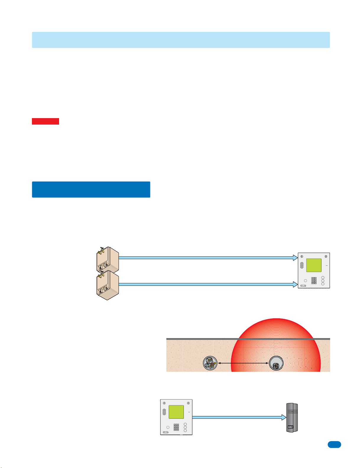
Use only the two (2) supplied transformers (or UL listed equivalent) to power the telephone entry and access control system
and any weigand input devices that use 16.5 VAC, 20 VA. DO NOT power any other devices (expansion boards, electric
strikes, magnetic locks etc.) from these power transformers.
Note: Transformers are not supplied on units sold outside the United States. An Inherently Protected Transformer must be used
to power this device. Use only transformers that are listed by a recognized testing laboratory to power the telephone entry
system.
Two 16.5 VAC, 20 VA for
1833, 1834 and 1835.
One 16.5 VAC, 20 VA and
One 16.5 VAC, 40 VA for 1837.
Up to 100 feet, use 18 AWG, 600 volt insulated wire.
Up to 200 feet, use 16 AWG, 600 volt insulated wire.
The importance of proper AWG power wiring cannot be over stressed!
Power wires are susceptible to noise and hum pickup; therefore
it is preferable that you keep power wire runs as short as possible.
“Optional” 12 volt .8 amp hour gel-cell batteries (DoorKing P/N 1801-008) can be installed to provide stand-by power in the
event of a power outage. Two batteries are required, one for the system power and one for the auxiliary terminal power.
Wire polarity does not matter
A
Z
CALL
2.1.2 Wire Runs
Be sure that you use proper wire that has an insulation
rated for an underground environment. All wires
should be placed in conduits. Proper pre-planning can
greatly ease the installation and wiring of this system.
Always check with the local building code to determine
the type of wire required in your municipality.
DO NOT run high voltage (115 V) power lines and low voltage/communication lines in the same conduit. These should be in
separate conduits at least six (6) inches apart. Be sure that all phone line wiring is twisted and completely isolated from ground.
Weigand wire runs are 500-feet maximum. Use
6-conductor stranded wire with overall shield. 18, 20,
22 or 24 gauge is sufficient for these connections.
1835-065-E-7-13
Underground Cutaway
Low Voltage/
Communication
Wire Conduit
A
Z
CALL
Electrical field from high voltage wires.
6” minimum
500 ft Max
High Voltage
Power Wire
(115 V) Conduit
Weigand Device
17
Page 20
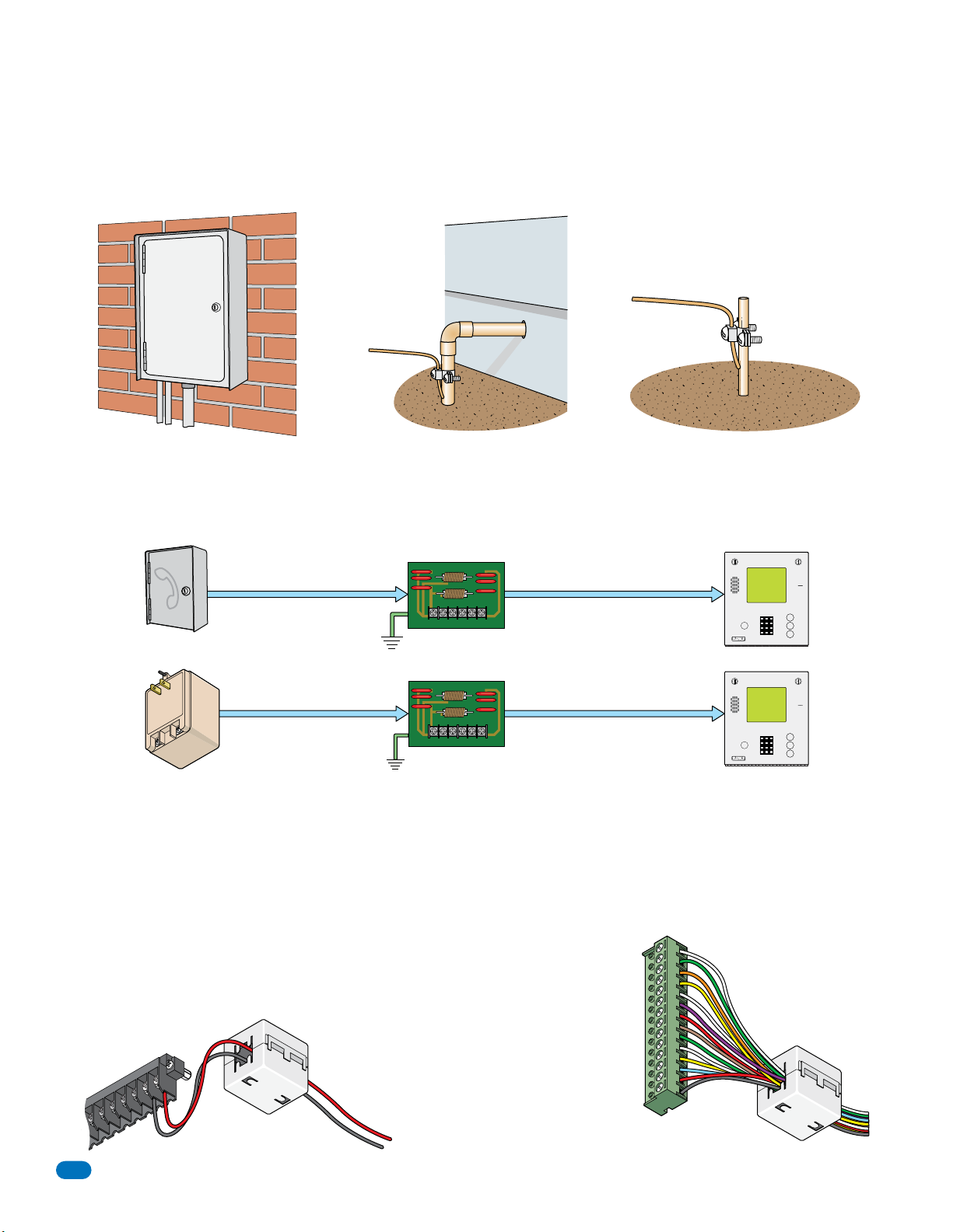
2.1.3 Grounding
Proper grounding of this system is a requirement. To be effective, ground connections should be made with a minimum 12
AWG, 600 volt insulated wire to a ground point within 10 feet of the telephone entry system. The ground point must be at an
electrical panel, a metallic cold water pipe that runs in the earth, or a stainless steel grounding rod driven at least ten (10) feet
into the soil. A architectural style mounting post anchored to concrete does NOT make a good ground.
Some Acceptable Ground Sources
IMPORTANT: Ground wire shown without
safety protection for clarity. Make sure
Electrical
Panel
Ground
Wire
ground wire is protected from being
touched or electrical shock could occur!
Ground
Wire
Ground to an existing electrical system.
Ground to a metallic cold water pipe.
Grounding rod 10 feet in soil.
2.1.4 Surge Suppression
The use of surge suppressors can significantly reduce the chance of component failure because of static charges or surges.
DoorKing recommends Installing a Phone Line surge suppressor (DoorKing P/N 1877-010 or equivalent) and a Low Voltage
surge suppressor (DoorKing P/N 1878-010 or equivalent) to help protect the entry system from power surges.
Phone Line Surge Suppressor
Phone Company
Install on each
16.5 VAC Transformer
Phone line surge suppressor
1877-010
PHONE LINE
within 10 ft of entry system.
Surge suppressor within 3 ft of ground source.
Low Voltage Surge Suppressor
Low voltage surge suppressor
1878-010
POWER LINE
within 10 ft of entry system.
Surge suppressor within 3 ft of ground source.
A
Z
CALL
A
Z
CALL
2.1.5 Expansion Boards and Elevator Control
I
f Expansion Boards are being used with this system, refer to the Installation and Wiring manual that came with the Expansion
boards, for detailed information on wiring Expansion boards to the PC programmable telephone entry system.
If Elevator Control is used with this system, refer to the Elevator Control Installation and Wiring manual for detailed information
on wiring the elevator control boards to this system and to the elevator push button control panel.
2.1.6 Ferrite Filter
The Telephone Entry System comes with two (2) Ferrite Filters (1834 only comes with
one). These will help prevent noise and hum pickup in the phone lines. One is installed
around the 16 VAC power wires on the main terminal #19 and #20. The second is
installed around all the wires connected to the aux terminal.
Clip Release
C
Main Terminal
1N
2RY
2C
14
18
#1
6AC
1
6AC
1
T
BA
O
N
1
20
19
18
7
1
16
15
Power Wires
on all models
To install the ferrite filter, release the
clip on the side to open the filter,
place the wires in the circular core
and snap the filter closed.
14
13
12
11
10
9
8
7
6
5
4
Aux Terminal
3
2
1
Auxiliary Wires
on 1833, 1835 and 1837 models
Clip Release
#2
1835-065-E-7-13
Page 21
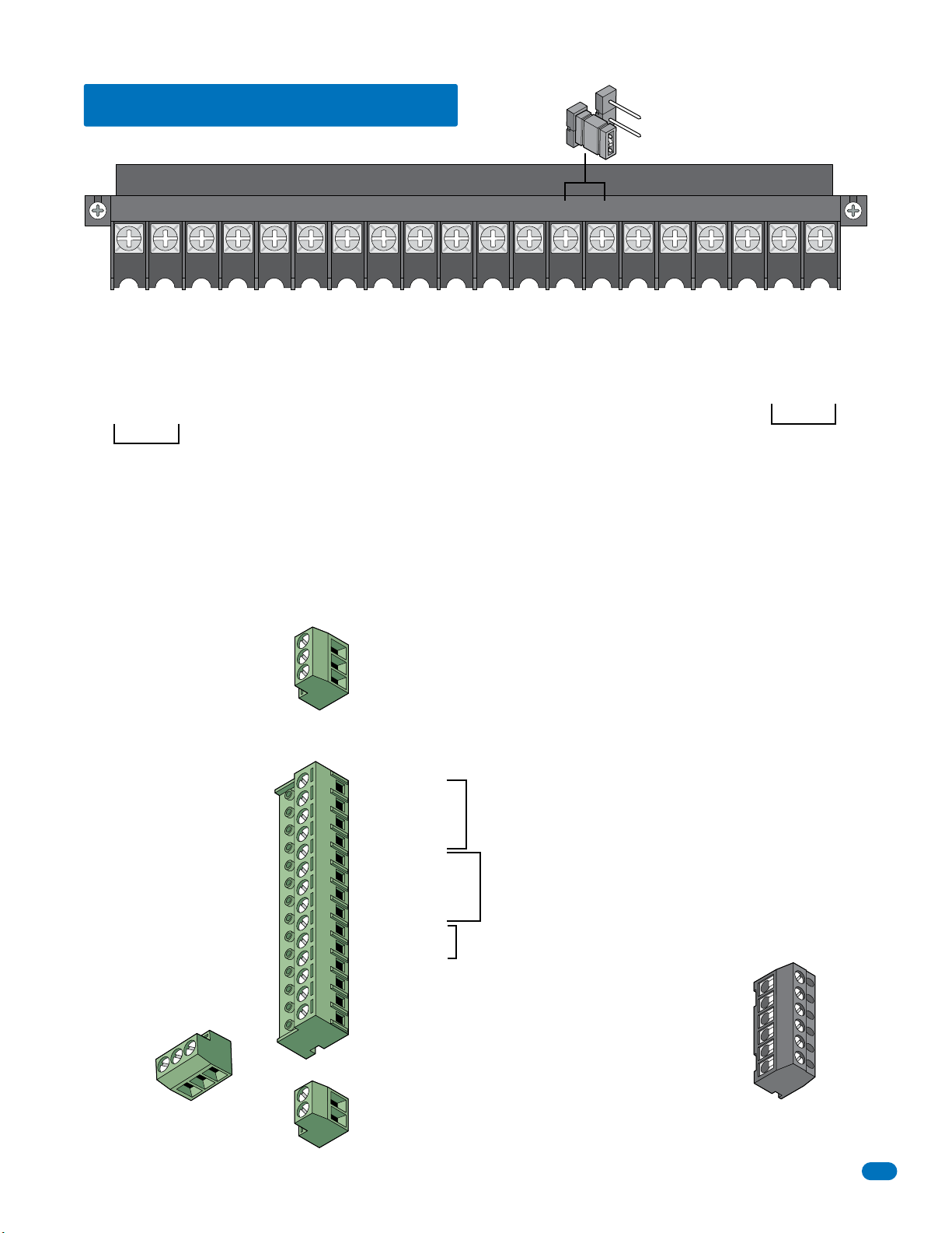
2.2 Terminal Descriptions
See section 4 on page 46 for the locations of the terminals on the circuit board.
Main Terminal
NO
Relay 2 Note: Normally Open and
NC
Normally Closed relay jumper is
used to set Relay 2 input on the
circuit board (See section 4.7).
PHONE
CGND
COMMICPSW
5VDCIMDSPKR
16AC16ACBAT1NO1NC1C2RY2CAZIMC
1234567891011121314151617181920
Phone Line Connection
1600 ft. max. with 22 AWG wire.
(Wiring MUST be twisted and completely isolated from the ground)
Earth Ground Only (See Section 2.1.3).
Phone Line Connection
800 ft. max. with 24 AWG wire.
Microphone Input.
Switch Input. A closure between terminals 4 and 6 will cause the designated relay(s) to activate for
the programmed strike time or dial a phone number – see 3.2.7. The Postal Switch is connected here.
Speaker Output.
Common for switch input #4, microphone,
speaker, AZ & CALL buttons and battery neg.
5 VDC Power for LED lighting.
(Not used).
“Z” Button Input.
(Not used).
Relay 2 Contact – 30 Volt, 3 Amp max.
Relay 2 Common – 30 Volt, 3 Amp max.
“A” Button Input.
Relay 1 Normally Open – 30 Volt, 3 Amp max.
Relay 1 Normally Closed – 30 Volt, 3 Amp max.
Relay 1 Common – 30 Volt, 3 Amp max.
Back-up Battery POSITIVE For Phone System Only. (connect negative to terminal 6)
16 VAC Input Power
16 VAC Input Power
100 ft. max. with 18 AWG wire.
200 ft. max. with 16 AWG wire.
20 VA min. for 1833, 1834 and 1835, 40 VA min. for 1837.
Elevator Control
Terminal
Non-Removable
Note: Connect to the Elevator Control Board (2348-010).
See Elevator Control Board Manual 2348-065 for more info.
3
1 DATA 1 – Connect to terminal 20 of elevator control board.
2
2 DATA 0 – Connect to terminal 21 of elevator control board.
1
3 COMMON – Connect to terminal 22 of elevator control board.
(NOT available for the 1834.)
(NOT available for the 1834.)
1835-065-E-7-13
Normally Open – 30 Volt, 3 Amp max.
Normally Closed – 30 Volt, 3 Amp max.
Common – 30 Volt, 3 Amp max.
C
NC
NO
Relay 0 Terminal
Non-Removable
Aux Terminal
Removable
14
14 +12 VDC Power.
13
13 Common.
12
12 DATA 1.
11
11 DATA 0.
10
10 +12 VDC Power.
9
9 Common.
8
8 DATA 1.
7
7 DATA 0.
6
6 16 VAC Output.
5
5 16 VAC Output.
4
4 Back-up Battery NEGATIVE (For Weigand Only).
3
3 Back-up Battery POSITIVE (For Weigand Only).
2
2 16.5 VAC Input Power – 20 VA.
1
1 16.5 VAC Input Power – 20 VA.
(Powers RS-232, elevator control and Weigand)
1834 Aux Terminal ONLY
Non-Removable
2
2 16.5 VAC Input Power – 20 VA.
1
1 16.5 VAC Input Power – 20 VA.
(Powers RS-232)
Note: The 14-pin aux terminal can be removed for easy
wiring. Expansion boards are connected here when used.
(NOT available for the 1834.)
Weigand input (Card Reader)
activates Relay 1 for
programmed strike time
Weigand input (Card Reader)
activates Relay 2 for
programmed strike time
For card readers that have additional
lighting for outdoor use.
See Expansion
Board Manual
2351-065 and
section 2.3.2,
2.3.3 for more
information.
Transmit Data 1
Receive Data 2
Request to Send 3
Clear to Send 4
Signal Ground - Shell 5
Not used 6
Note: Located in the upper left corner of circuit
board. The 6-pin terminal can be removed for
easy wiring. Connects a PC (See Section 2.4.2).
RS-232
Terminal
Removable
1
2
3
4
5
6
19
Page 22

2.3 Telephone Entry System Wiring
2.3.1 ALL Telephone Entry Systems - NO Expansion Boards
RS 232
1
2
3
4
5
6
Elevator Control
terminal is NOT
available for 1834.
ELEVATOR
RS-232
PC Connection See section 2.4.2 for wiring RS-232.
MIC
VOL
321
321
SPK
VOL
FEED
BACK
321
1816
HF
HS
Central Office
Phone Line Input
touch tone, loop start
“PHONE”
“PHONE”
Wiring MUST be twisted and
completely isolated from ground.
See section 2.1.4.
“CGND” Ground
See section 2.1.3.
“PSW” & “COM”
Switch Input -
See section 1.6 for Postal lock
A switch closure across these
terminals activates Relay 1 for its
See section 3.2.7 Switch Input
1833, 1835 & 1837 Systems:
Control up to 3 entry points with ONLY the system circuit board.
Note: Separate elevator control board required for elevator control.
Note: When more than 3 entry points are needed to be controlled,
expansion boards will be required to accomplish this, see next 2 pages.
1834 System:
Control up to 2 entry points with the circuit board (Non-expandable).
connection.
programmed strike time.
Feature.
CLK
SEN
RING
Main Terminal
KEYPAD
ON
1833, 1835 and 1837 ONLY
MASTER
CODE
OFF
5VDCIMDSPKRCOMMICPSWCGNDPHONE
Relay 0
NO NC C
Elevator Control Terminal
1833, 1835 and 1837 ONLY
Auxiliary Terminal 1834 ONLY
Relay 2 Jumper
NO
NC
16AC16ACBAT1NO1NC1C2RY2CAZIMC
Red (Pos)
Black (Neg)
1
2
3
#11 thru #14
These terminals will activate
Relay 1 for its programmed
Red
strike time.
Black
White
#7 thru #10 These terminals will
Green
activate Relay 2 for its programmed
Red
strike time.
Black
White
Green
1833, 1835 and 1837 ONLY
Auxiliary Terminal
Power wire
polarity does
not matter.
16.5 VAC
16.5 VAC
12345 67891011121314
16.5 VAC
16.5 VAC
12
BOTH transformers
MUST be installed
for the system to
operate.
20 VA
40 VA
“BAT” & “COM” - 12 VDC Back-Up Battery Input (Phone System)
Back-up battery power for the phone system ONLY. A separate back-up battery is used for Weigand devices
connected to the auxiliary terminal when back-up battery power is being used. See aux terminal #3 & #4.
Black (Neg)
Red (Pos)
20 VA
Power wire
polarity does
not matter.
20 VA
Power Input for Phone System
20 VA power for the 1833, 1834 or 1835 phone system ONLY.
DO NOT use a 40 VA transformer for the 1833, 1834 or 1835.
Power Input for 1837 Phone System
40 VA power for the 1837 phone system ONLY.
DO NOT use a 20 VA transformer for the 1837.
“1NO” - Normally Open (NO)
“1NC” - Normally Closed (NC)
“1C” - Common (C)
“2RY” - Contact (NO or NC)
“2C” - Common (C)
NO - Normally Open
NC - Normally Closed
C - Common
19
20 - DATA - 1
21 - DATA - 0
22 - COMMON
23
24
“Optional” Elevator Control
25
26
Board Required for Elevator
27
28
Control
29
Power for relays on elevator control board is NOT provided
30
by the system. Use separate UL listed power supply.
31
See Elevator Control Board Manual 2348-065.
32
33
34
35
36
Weigand Input (Relay 1)
Card Reader Input: Use 6 conductor, stranded
with overall shield. 18, 20, 22 or 24 gauge.
See section 2.1.2.
#5 & #6 - 16 VAC Output: Can be used to power lights on
card readers that have additional lighting for outdoor use.
#3 & #4 - 12 VDC Back-Up Battery Input (Aux Term)
Back-up battery power for Weigand inputs ONLY. NOT available for 1834.
A separate back-up battery is needed for the phone system.
Power Input for Aux Terminal
14-Pin aux terminal on 1833, 1835 and 1837 circuit boards.
Powers RS-232, elevator control and Weigand inputs.
Power Input for 1834 Aux Terminal
2-Pin terminal only on the 1834 circuit board.
Powers RS-232.
Relay 1 Input
Relay 2 Input
“2RY” Contact is set NO or NC with Relay 2 Jumper on board.
See section 4.7
Relay 0 Input
Separate terminal on the circuit board. NOT available for 1834.
(Left terminal on elevator control board)
Weigand Input (Relay 2)
Card Reader Input: Use 6 conductor, stranded
with overall shield. 18, 20, 22 or 24 gauge.
See section 2.1.2.
Power Transformers:
Use ONLY 16.5 VAC UL
Listed Transformer.
Run 18 AWG wire up to
100 Ft. Run 16 AWG wire
up to 200 Ft.
See section 2.1.1, 2.1.3
and 2.1.4 for further
information.
Relays activate a door lock
or a gate operator for their
programmed strike time at
a controlled access point.
Basic Door Control ComponentsBasic Gate Control Components
500 ft max.
Card
Reader
To a Weigand Input Aux. Terminal
To #5 & #6 aux. terminal
for additional lighting on
card reader.
Gate Operator
To a Relay Input
Gate Operator
is wired to
Normally Open
(NO) relay
input.
To a
Weigand
Input Aux.
Terminal
500 ft max.
To a
Relay Input
Lock Power
UL listed
Card Reader
Door
Lock
Power for electric strike or magnetic
lock is NOT provided by the system.
Use separate UL listed power supply.
20
Door Locks
Electric strike is wired
to Normally Open (NO)
relay input.
Magnetic lock is wired to
the Normally Closed (NC)
relay input.
1835-065-E-7-13
Page 23
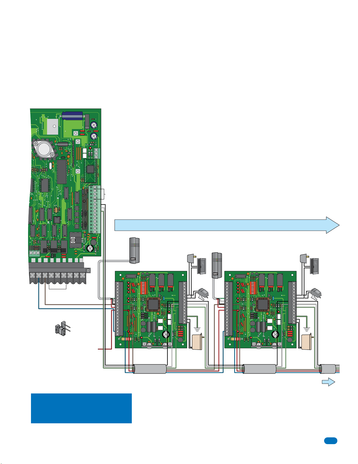
2.3.2 Wiring Up to 8 Expansion Boards - 1833, 1835 and 1837 Systems
Wiring these telephone entry systems are the same as section 2.3.1 EXCEPT for the expansion board connection. Up to 8
boards can be wired to the circuit board’s Aux Terminal #7 thru #9 instead of a weigand input device. To connect more than 8
expansions boards, see section 2.3.3 on the next page. All expansion boards must have their own power source. See the
Expansion Board Manual 2351-065 for further information BEFORE wiring expansion boards.
Telephone
Entry System
Circuit Board
Relay 0
Relay 2 Jumper
NO
NO NC C
Relay 2 Input
“2RY” Contact is set NO with Relay 2 Jumper on board.
NC
Main Terminal
Relay 1
Brown
Blue
NO
Red - NO circuit board connection.
16AC16ACBAT1NO1NC1C2RY2CA
NC
ELEVATOR
Auxiliary Terminal
The model 2351 Expansion Board allows you to expand the number of remote entry points
that the 1833, 1835, 1837 telephone entry systems can control. One expansion board is
required for EACH remote entry point.
1
2
3
Note: DO NOT connect expansion boards
to Aux #11,Aux #12 or Aux #13.
Aux Terminal Connection
Black - Aux #9 connection.
White - Aux #8 connection.
Green - Aux #7 connection.
• Maximum wire run between Expansion boards 1-8 is 500 feet total.
• Do not use twisted pair wire with weigand output format.
3-10
• Proper grounding is required! Ground wire should be a minimum 12 AWG.
Lock Power
UL listed
Expansion Boards 1 to 8
12345 67891011121314
Connect card
reader using 4
conductor,
stranded with
overall shield. 18,
20, 22 or 24
gauge.
Card Reader
P2: #6 - #9
Lock Power
UL listed
System Relays
Card Reader
P2: #6 - #9
Expansion Board 1 Expansion Board 2
Door Lock
P1P2
1
2
3
4
5
6
7
8
9
10
11
12
13
14
15
16
17
18
Blue #17
Red #10
ON
1
2 3 4 5 6 7 8
NC
NONCNONCNO
POWER
Brown #8
Black #7
White #8
Green #9
P1: #5
1
or Gate
2
Operator
3
4
5
6
7
8
9
10
11
Ground #12 Ground #12
12
13
14
16 VAC
20 VA
Board Power
UL listed
P1: #13 & #14
Brown #8
Blue #17
Red #10
1
2
3
4
5
6
7
8
9
10
11
12
13
14
15
16
17
18
ON
1
2 3 4 5 6 7 8
NC
NONCNONCNO
POWER
Black #7
White #8
Green #9
P1P2
1
2
3
4
5
6
7
8
9
10
11
12
13
14
16 VAC
Board Power
UL listed
P1: #13 & #14
Door Lock
P1: #5
or Gate
Operator
20 VA
1833, 1835 & 1837 Systems with
Up to 8 expansion boards connected:
Control up to 2 entry points (Relay 0, Relay 1) with the system circuit board.
Control up to 8 more remote entry points with expansion boards.
Note: Separate elevator control board required for elevator control.
1835-065-E-7-13
Connect expansion boards using 6 conductor, stranded with overall
shield. 18, 20, 22 or 24 gauge. Shield runs continuous. Float the
shield, DO NOT connect shield to 2351-010 board common.
Expansion Board Power: You may power up to four (4) expansion
boards from a single 16 VAC, 20 VA power transformer.
18 AWG wire up to 100 Ft.
16 AWG wire up to 200 Ft.
It is advisable to keep power wire runs as short as possible.
To Expansion
Boards 3 thru 8
21
Page 24
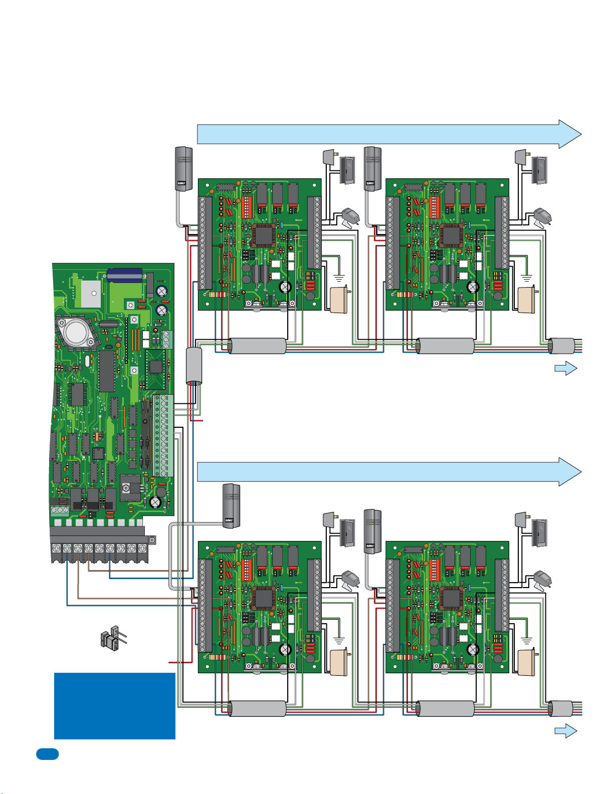
2.3.3 Wiring 9 to 16 Expansion Boards - 1833, 1835 and 1837 Systems
Wiring these telephone entry systems are the same as section 2.3.1 EXCEPT for the expansion board connection. From 9 to 16
boards can be wired. The FIRST 8 boards MUST connect from #7 thru #9 on the aux terminal. Boards 9 to 16 MUST connect
from #11 thru #13 on the aux terminal. All expansion boards MUST have their own power source. See the Expansion Board
Manual 2351-065 for further information BEFORE wiring expansion boards.
• Maximum wire run between Expansion boards 9-16 is 500 feet total.
• Do not use twisted pair wire with weigand output format.
11-18
• Proper grounding is required! Ground wire should be a minimum 12 AWG.
Lock Power
UL listed
Expansion Board 10
NC
NONCNONCNO
Black #7
White #8
P1P2
1
2
3
4
5
6
7
8
9
10
11
12
13
14
Board Power
P1: #13 & #14
Green #9
ON
1
1
2
3
4
5
6
7
8
9
10
11
12
13
14
15
16
17
18
2 3 4 5 6 7 8
POWER
To Expansion
• Maximum wire run between Expansion boards 1-8 is 500 feet total.
• Do not use twisted pair wire with weigand output format.
3-10
• Proper grounding is required! Ground wire should be a minimum 12 AWG.
Lock Power
UL listed
ON
1
1
2
3
4
5
6
7
8
9
10
11
12
13
14
15
16
17
18
2 3 4 5 6 7 8
POWER
P1P2
1
2
3
4
NC
NONCNONCNO
5
6
7
8
9
10
11
12
13
14
Board Power
P1: #13 & #14
Black #7
White #8
Green #9
To Expansion
Boards 3 thru 8
Door Lock
P1: #5
or Gate
Operator
16 VAC
20 VA
UL listed
Boards
11 thru 16
Door Lock
P1: #5
or Gate
Operator
16 VAC
20 VA
UL listed
Connect card reader using 4
conductor, stranded with overall
shield. 18, 20, 22 or 24 gauge.
Telephone
Entry System
Circuit Board
Relay 0
Relay 2 Jumper
NO
NO NC C
Relay 2 Input
“2RY” Contact is set NO with Relay 2 Jumper on board.
1833, 1835 & 1837 Systems
with Up to 16 expansion
boards connected:
Control 1 entry point (Relay 0) with system circuit board.
Control up to 16 more remote entry points with expansion
boards.
Note: Separate elevator control board required for elevator
control.
22
NC
Main Terminal
Brown
Brown
Blue
NO
Red - NO circuit board connection.
16AC16ACBAT1NO1NC1C2RY2CA
Blue
Relay 1 Input
NC
ELEVATOR
Auxiliary Terminal
Expansion Boards 9 to 16
Card Reader
P2: #6 - #9
Expansion Board 9
ON
1
1
2
3
4
5
6
7
8
9
10
11
12
13
14
15
16
17
18
1
2
3
Aux Terminal Connection 9 to 16
Black - Aux #13 connection.
White - Aux #12 connection.
Green - Aux #11 connection.
Red - NO circuit board connection.
Battery Back-up power connection - optional.
Aux Terminal Connection 1 to 8
Black - Aux #9 connection.
White - Aux #8 connection.
Green - Aux #7 connection.
12345 67891011121314
Expansion Boards 1 to 8
2 3 4 5 6 7 8
POWER
Blue #17
Red #10
Brown #8
Connect expansion boards using 6 conductor,
stranded with overall shield. 18, 20, 22 or 24
gauge. Shield runs continuous. Float the
shield, DO NOT connect shield to 2351-010
board common.
Card Reader
P2: #6 - #9
Expansion Board 1 Expansion Board 2
ON
1
Blue #17
Red #10
2 3 4 5 6 7 8
POWER
Brown #8
1
2
3
4
5
6
7
8
9
10
11
12
13
14
15
16
17
18
Connect expansion boards using 6 conductor, stranded with overall
shield. 18, 20, 22 or 24 gauge. Shield runs continuous. Float the
shield, DO NOT connect shield to 2351-010 board common.
Lock Power
UL listed
P1P2
1
2
3
4
NC
NONCNONCNO
5
6
7
8
9
10
11
12
13
14
Black #7
White #8
Green #9
Lock Power
UL listed
P1P2
1
2
3
4
NC
NONCNONCNO
5
6
7
8
9
10
11
12
13
14
Black #7
White #8
Green #9
Board Power
P1: #13 & #14
Board Power
P1: #13 & #14
System Relays
Card Reader
P2: #6 - #9
Door Lock
P1: #5
or Gate
Operator
Ground #12 Ground #12
16 VAC
20 VA
UL listed
Expansion Board Power: You may power up to four (4) expansion
boards from a single 16 VAC, 20 VA power transformer.
18 AWG wire up to 100 Ft.
16 AWG wire up to 200 Ft.
It is advisable to keep power wire runs as short as possible.
Brown #8
Blue #17
Red #10
The model 2351 Expansion Board allows you to expand the
number of remote entry points that the 1833, 1835, 1837
telephone entry systems can control up to 16. One expansion
board is required for EACH remote entry point. Two sets of 8
boards get wired to the entry systems circuit board.
System Relays
Card Reader
P2: #6 - #9
Door Lock
P1: #5
or Gate
Operator
Ground #12 Ground #12
16 VAC
20 VA
UL listed
Brown #8
Blue #17
Red #10
1835-065-E-7-13
Page 25
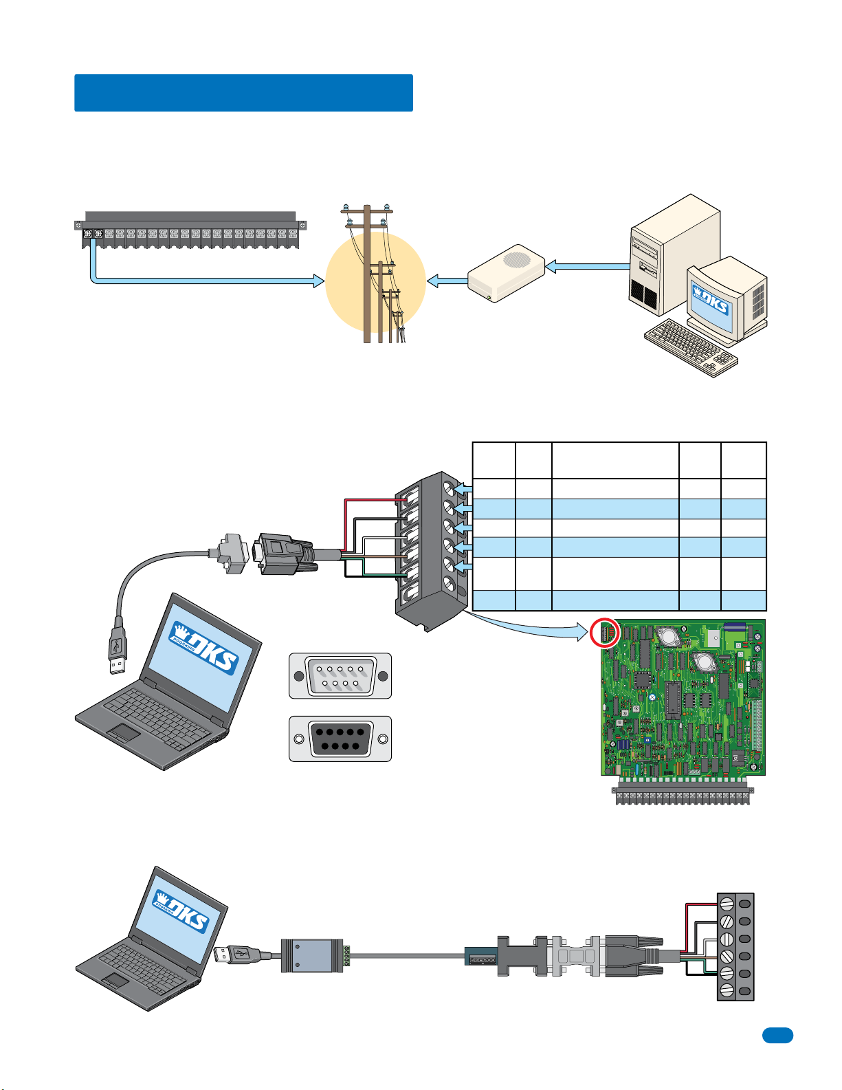
2.4 PC Connection Options
Connecting the telephone entry system to a PC may be accomplished by SEVEN (7) different methods in this section.
2.4.1 Phone Modem Connection
Use your EXISTING modem to connect your PC to the entry system. Phone modem can ONLY connect to one entry system at a
time.
Main Terminal
5VDCIMDSPKRCOMMICPSWCGNDPHONE
16AC16ACBAT1NO1NC1C2RY2CAZIMC
Telephone Entry System
Phone Company
2.4.2 Direct Connection using the Circuit Board’s RS-232 Terminal
Requires DoorKing RS-232 9-pin cable P/N 1818-040 and RS-232 to USB Adapter P/N 1835-037 to connect to PC. Sending
data to MULTIPLE entry systems in one programming step with RS-232 is limited to the number of RS-232 Ports installed.
RS-232 to USB
Adapter
P/N 1835-037
SOFTWARE
INSTALLED
Your PC
RS-232
DB-9 Pin Plug
P/N 1818-040
100 ft Max.
DB-9 Pin #s
1234
678 9
54321
9 8 76
Red
Black
White
Brown
Green
Shield
5
Unlimited Connection Distance
Slow Data Transfer Rate
Your External
Phone Modem
or
Internal PC
Phone Modem
RS-232
Terminal
1
2
3
4
5
6
The 6-pin terminal can be
removed for easy wiring.
Male End
Female End
Board
Wire
Color
Red
Black
White
Brown
Green/
Shield
Entry System
Circuit Board
Pins
1
2
3
4
5
6
Function
Transmit Data
Receive Data
Request to Send
Clear to Send
Signal Ground - Shell
Not Used
Telephone
Your PC
Board
RS-232
FEED
BACK
321
SOFTWARE
INST
ALLED
DB-9
MIC
VOL
321
321
SPK
VOL
CLK
SEN
ON
MASTER
CODE
OFF
KEYPAD
RING
Main Terminal
Pins
3
2
7
8
5
NO
NC C
NO
DB-25
Pins
2
3
4
5
7
NC
16AC16ACBAT1NO1NC1C2RY2CAZIMC5VDCIMDSPKRCOMMICPSWCGNDPHONE
ELEVATOR
1
2
3
1234567891011121314
2.4.3 RS-232 Terminal using RS-422/USB Connection
Requires RS-422 adapter kit (DoorKing P/N 1508-055). Sending data to MULTIPLE entry systems in one programming step with
RS-422 is limited to the number of USB Ports installed.
Terminal
Telephone
Entry
System
RS-232
1835-065-E-7-13
SOFTWARE
INSTALLED
Your PC
USB
RS-422 to USB
Adapter
Cat-5 Cable
Not included
4000 ft Max.
RS-232 to RS-422
Adapter
TD(A)
TD(B)
RD(A)
RD(B)
GND
+12V
RS-232
1
2
3
4
5
6
See 2.4.2
23
Page 26
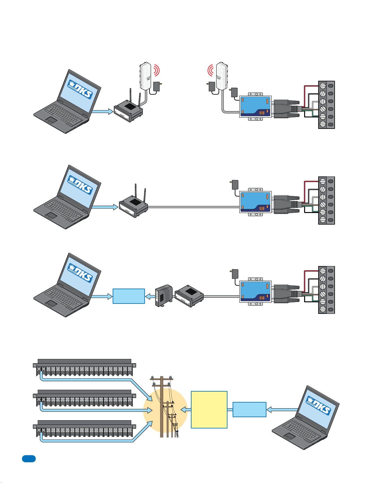
2.4.4 RS-232 Terminal using Wireless Connection
Requires TCP/IP Converter Kit (DoorKing P/N 1830-175) and Wireless Adapter Kit (DoorKing P/N 1815-510 - 1 Remote,
P/N 1815-511 - 2 Remotes, P/N 1815-512 - 3 Remotes). Managing to up to three entry systems with your PC.
Home
(Administrator)
9 VDC Power
DoorKing
TCP/IP Converter
RS-232
Terminal
Telephone
Entry
System
RS-232
See 2.4.2
SOFTWARE
INSTALLED
Your PC
Wired or
Wireless
Remote 1
Router
Your
24 VDC
Power
Cat-5 Cable
1000 ft Max.
Line-of-Sight
24 VDC
Power
Cat-5 Cable
2.4.5 RS-232 Terminal using TCP/IP Converter LAN Connection (Local Area Network)
Requires TCP/IP Converter Kit (DoorKing P/N 1830-175). Sending data to MULTIPLE entry systems in one programming step
with TCP/IP is limited to the number of ports on your router.
RS-232
Terminal
SOFTWARE
INSTALLED
Your PC
Wired or
Wireless
Your
Router
9 VDC Power
Cat-5 Cable
Not included
325 ft Max.
DoorKing
TCP/IP Converter
Telephone
Entry
System
RS-232
See 2.4.2
2.4.6 RS-232 Terminal using TCP/IP Converter WAN Connection (Wide Area Network)
Requires TCP/IP Converter Kit (DoorKing P/N 1830-175). Can send data to MULTIPLE entry systems in one programming step.
RS-232
Terminal
SOFT
INSTALLED
WA
Your PC
RE
Wired or
Wireless
Internet
Your
Modem
Your
Router
9 VDC Power
Cat-5 Cable
Not included
325 ft Max.
DoorKing
TCP/IP Converter
Telephone
Entry
System
RS-232
See 2.4.2
1
2
3
4
5
6
1
2
3
4
5
6
1
2
3
4
5
6
2.4.7 DoorKing DKS Internet-Modem Server
NO additional hardware required. You can send data to MULTIPLE entry systems in one programming step.
Multiple Entry Systems
Telephone Entry System
Main Terminal
5VDCIMDSPKRCOMMICPSWCGNDPHONE
Telephone Entry System
Main Terminal
5VDCIMDSPKRCOMMICPSWCGNDPHONE
Telephone Entry System
Main Terminal
5VDCIMDSPKRCOMMICPSWCGNDPHONE
24
16AC16ACBAT1NO1NC1C2RY2CAZIMC
Unlimited Connection Distance
Fast Data Transfer Rate
16AC16ACBAT1NO1NC1C2RY2CAZIMC
16AC16ACBAT1NO1NC1C2RY2CAZIMC
Phone Company
DKS
Internet
Modem
Internet
Server
The IM Server is fee based. Visit
http://www.doorking.com/IMServer
for more information.
Wired or
Wireless
SOFTWARE
INSTALLED
Your PC
1835-065-E-7-13
Page 27
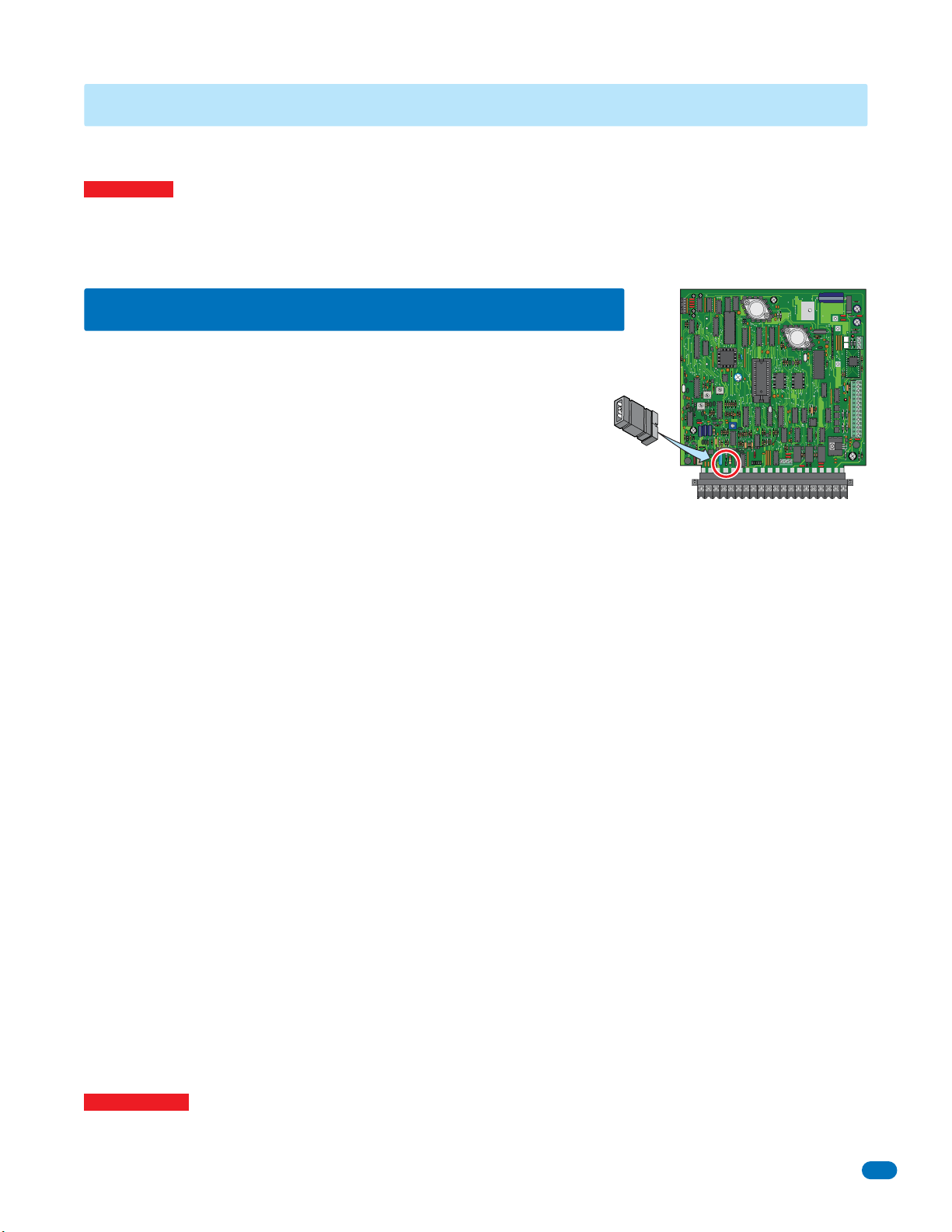
SECTION 3 - PROGRAMMING
We strongly suggest that you read these programming instructions in their entirety before beginning any programming of
this telephone entry system.
IMPORTANT! Many of the advanced features available with this telephone entry system CANNOT be programmed from the
system keypad. These advanced features include relay hold open time zones, security levels, elevator control options and
programming via the internet using DKS servers. If any of these advanced features are used, the system MUST be programmed
with a PC using the DoorKing Remote Account Manager for Windows software, VERSION 6.3.b or higher. Refer to the software
help screen for more information on these advanced features.
RS-232
3.1 General Programming Information
ELEVATOR
The DoorKing PC Programmable Telephone Entry System is primarily programmed by
using the DoorKing Remote Account Manager for Windows software. However, the
system can also be partially programmed from the keypad on the front of the entry
system.
Programming the entry system can also be preformed off-site using a user supplied
PC with the DKS software loaded on it. Make sure the RING pin jumper is in place on
RING
the circuit board, which was factory installed. See section 4.6 for more information.
The PC programmable telephone entry systems (except 1834) have three relays on the circuit board, all of which are programmable for any function required. These relays are designated as Relay 0 (R 0), Relay 1 (R 1), and Relay 2 (R 2). If Expansion
boards are used with this system, it is very important that you understand the function of these three relays. The weigand input
auxiliary terminals (also the Expansion board input terminals) can only cause R 1 or R 2 to activate. Weigand input devices
CANNOT cause R 0 to activate. Therefore, if Expansion boards are used with this system, R 0 MUST be designated as the
PRIMARY relay, and R 1 and R 2 are then designated as Expansion board command (CMD) relays with R 2 controlling Expan-
sion boards 1 through 8 (system relays 3-10), and R 1 controlling Expansion boards 9 through 16 (system relays 11-18). The
PRIMARY relay is the relay that a resident activates from their telephone after receiving a call from a visitor. When Expansion
boards or other weigand devices are used with the system, be sure that R 0 is programmed to respond to the tone open number
(typically 9), the postal switch input, and the rotary dial 9 function.
Device codes, expansion boards, anti-pass back (APB) and elevator control features are NOT AVAILABLE with the 1834 system.
MIC
VOL
321
321
SPK
VOL
FEED
BACK
321
CLK
SEN
ON
MASTER
CODE
OFF
KEYPAD
RING
NO
NC
NO
NC C
5VDCIMDSPKRCOMMICPSWCGNDPHONE
16AC16ACBAT1NO1NC1C2RY2CAZIMC
1
2
3
1234567891011121314
3.1.1 Programming from a PC
Prior to programming the system with a PC and the DoorKing Remote Account Manager for Windows Software, there is certain
information that you must know and must program into the system before the computer can communicate with the system. See
next page section 3.2 to set-up the telephone entry system for PC programming. Programming the system with a PC may be
accomplished by 1) Phone modem, 2) RS-232 direct connection, 3) RS-422 direct connection, 4) Wireless Connection,
5) TCP/IP LAN direct connection, 6) TCP/IP WAN or Internet, 7) DK Internet-Modem Server. See section 2.4 PC Connection
Options for all layouts and additional hardware that is needed for each. All options require the DoorKing Remote Account
Manager for Windows Software VERSION 6.3.b or higher.
3.1.2 Programming from the Telephone Entry System Keypad
Follow the programming instructions as described in each section of this manual. The system will prompt you with short tones
(beep) when programming steps have been followed correctly, and with a long tone (beeeeeep) when the programming step is
ended. The LCD display will also assist you in viewing the information that you are programming (NOT AVAILABLE with the
1833 system). It is highly recommended that you complete the resident information in section 7 in back of this manual prior to
programming from the system keypad. This will provide you with the information needed to complete the manual programming
sequence (sections 3.2.1 through 3.2.8). When programming from the system keypad, after each programming step is
performed correctly, a short tone (beep) will be heard. When the programming session is ended, a long tone (beeeeeep) will be
heard.
Important Note: Relay hold open time zones, security levels, holiday schedules, anti-pass back IN / OUT tables, anti-pass back
re-sync schedules and elevator control features CANNOT be programmed from the system keypad. These advanced features
can only be programmed from a PC using the DoorKing Remote Account Manager Software.
1835-065-E-7-13
25
Page 28
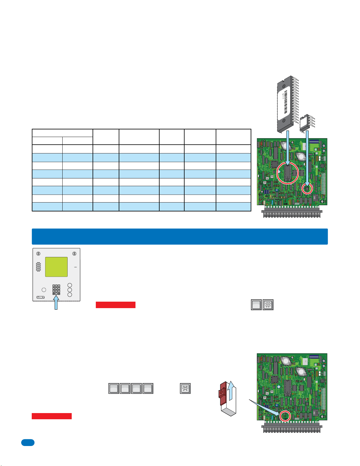
3.1.3 System Memory Chip Identification
?
9
6
3
0
OPER
WXYZ
TUV
PQRS
MNO
JKL
GHI
DEF
ABCSPSP
0
OPER
Beginning in January, 2010, all DKS 1830 series telephone entry systems come standard with 3000 memory (APB - anti-pass
back) chips installed in the system. The information below is to assist you with programming older systems or when there is a
need to change the memory chips to match a chip set on another system already installed. Prior to starting the programming
of the PC programmable telephone entry system, you must know the memory capacity and type of the EEPROM chips that
are installed in the unit. This can be determined by inspecting the small chip that has a tag
listing the memory size on it and will be labeled APB if anti-pass back is enabled. The memory
size determines the number of residents, vendors, four-digit entry codes and device codes that
can be stored in the system. APB indicates that the chip set has anti-pass back capability. The
table shows the valid numbers available with each memory level.
If you need to remove and replace the chips, see Section 1.5 Memory Chip Replacement.
Chip Part Number
Standard APB
1835-150
1835-151
1835-152
1835-153
1835-154
1835-155
1835-156
1835-157
1835-140
1835-141
1835-142
1835-143
1835-144
1835-145
1835-146
1835-147
System
Memory
25
75
125
250
500
1000
2000
3000
Phone Number
Capacity
25
75
125
250
500
1000
2000
3000
Name
Capacity
25
75
125
250
500
1000
2000
3000
Entry Code
Capacity
25
75
125
250
500
1000
2000
3000
Device Code
Capacity
625
1875
3125
6250
8000
8000
8000
8000
RS 232
FEED
BACK
sn XX
0000010100010
THIS SIDE UP
1835
APB
00
30
ELEVATOR
MIC
VOL
321
321
SPK
VOL
321
CLK
SEN
ON
MASTER
CODE
OFF
KEYPAD
RING
NO
NC
NO
NC C
16AC16ACBAT1NO1NC1C2RY2CAZIMC5VDCIMDSPKRCOMMICPSWCGNDPHONE
1
2
3
1234567891011121314
Chip Locations
3.2 Set-up Telephone Entry System for PC Programming
Prior to using a PC to program this PC Programmable Telephone Entry System with the DoorKing Remote
Account Manager for Windows software, the programming steps in section 3.2.1 through 3.2.8 factory
settings MUST be reviewed or re-programmed if necessary (most factory settings are typically desired).
There is no need to re-program these settings unless you want to change them. For easy reference, refer
DEF
ABC
11223
MNO
JKL
GHI
44556
WXYZ
TUV
PQRS
77889
OPER
0
System Keypad
3.2.1 Master Code
This programming step sets the system MASTER CODE. The master code is the four-digit number REQUIRED to gain access to
the system memory. You need to know the master code prior to programming the system with the PC, or to perform ANY of
the programming functions on the following pages. It MUST be programmed in from the system keypad.
NO Factory setting - Each entry system’s master code MUST be unique.
See section 4.5 for more information about the master code switch.
1. Open the cabinet of the telephone entry system and turn the master code switch ON.
2. Enter a four-digit master code then press (beep).
3. Turn the master code switch OFF and close the cabinet.
Important Note: There is no way of retrieving the master code after it has been
programmed in. If you forget it, you will have to program in a new one but all other
previously programmed information will remain intact.
to the chart on page 29 that list the various programming functions and their factory default settings.
A
Section 3.2.1 through 3.2.8 can ONLY be programmed from the System Keypad. There is NO program-
Z
ming sequence in the Remote Account Manager Software to program these features with.
CALL
Important Note: If you make a mistake while programming, press keys at the same time
OPER
0
to escape from programming no matter how much has been completed, then begin again at step 1.
RS 232
MIC
???????
ON
MASTER
CODE
OFF
VOL
321
321
SPK
VOL
FEED
BACK
321
CLK
SEN
ON
MASTER
CODE
OFF
KEYPAD
RING
5VDCIMDSPKRCOMMICPSWCGNDPHONE
NO
NC C
ELEVATOR
1
2
3
1234567891011121314
NO
NC
16AC16ACBAT1NO1NC1C2RY2CAZIMC
26
1835-065-E-7-13
Page 29
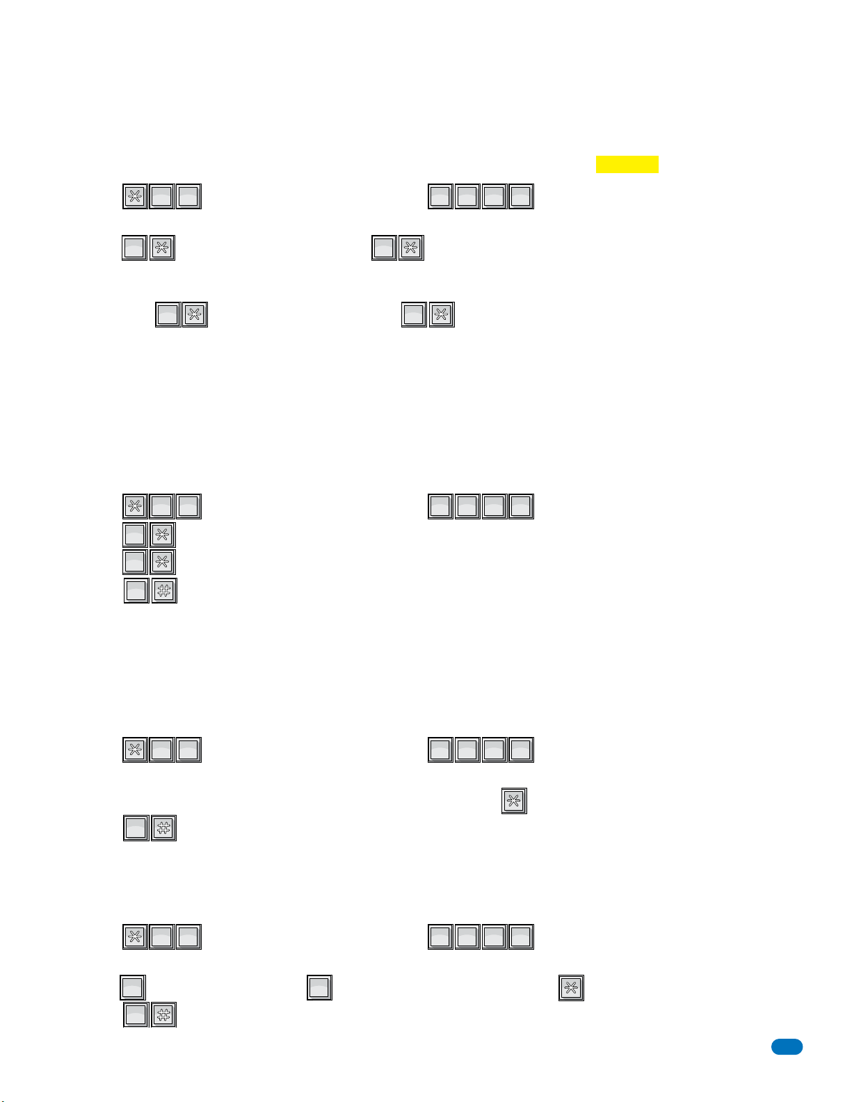
3.2.2 Number of Area Codes Allowed
? ? ? ?
0
OPER
6
MNO
0
OPER
0
OPER
1
SP
1
SP
? ? ? ?
8
TUV
7
PQRS
0
OPER
1
SP
0
OPER
? ? ? ?
6
MNO
3
DEF
0
OPER
? ? ? ?
5
JKL
1
SP
1
SP
0
OPER
0
OPER
This programming step sets the system to allow either “up to 10” or “up to 255” alternate area codes (AAC) to be programmed
into the system. The factory default is set to 10 area codes. Therefore, if you require 10 (or less) area codes, this step can be
skipped. 255 area codes are available on REV E and higher circuit boards. REV D and lower boards have 10 area codes only;
therefore this programming step is not required on systems with these circuit boards.
Factory setting = 0 (10 area codes)
MNO
1. Press and enter your four-digit MASTER CODE (beep).
OPER
?
The LCD display on the 1834, 1835 and 1837 systems will read: 10 AAC=0 255 AAC=1
SP
OPER
2. Enter (beep) for 10 area codes OR enter (beep) for 255 area codes.
The display will read: ERASE MEM? 1=Y 0=N. (Choosing 1 WILL ERASE the memory and WILL evoke the area code choice.
CAUTION:
When changing an
existing 1830 system from 10 to
255 or vice-versa, ALL existing
programmed memory will be
erased but the programmed screen
display messages, Section 3.4.
Choosing 0 WILL NOT ERASE memory and WILL NOT evoke the choice).
3. Enter either (beeeeeep) to set the change OR (beeeeeep) to cancel the change.
SP
OPER
3.2.3 Call-up Operation when Interfacing with DoorKing 1816 or 1820 Systems
This feature is ONLY used when the telephone entry system is interfaced with a DoorKing 1816 or 1820 Telephone Intercom
system under certain special applications. This CALL-UP feature provides special programming that will allow the system to
call the phone number of a CO (Central Office) line connected to these systems. Once the 1816 or 1820 answers the call, the
system will automatically send out DTMF tones that will activate the CALL-UP feature in the 1816 or 1820 system, and then
send the four digit directory code to the resident selected by the visitor. This allows visitors to contact tenants in the building
that do not have CO phone service through the telephone entry system. Refer to the 1816 / 1820 Installation Manual, and check
with your DoorKing representative on the special applications that this feature is used for.
Factory setting = OFF (DO NOT turn ON unless interfacing with a 1816 or 1820)
PQRS
1. Press and enter your four-digit MASTER CODE (beep).
2. Enter (beep) to turn the call-up feature OFF.
Enter (beep) to turn the call-up feature ON. Special applications ONLY.
3. Press together to end this programming sequence (beeeeeep).
3.2.4 Resident Elevator Button Relay Time
When elevator control is in use, an access device such as a card reader must be installed in the elevator car to allow residents
access to the floors in the building. The time interval that the button(s) is “live” after the resident activates the access device is
dependant on the revision level of the 1830 series circuit board, not the 2348 elevator control board. The relay time interval for
OPER
SP
OPER
TUV
1830 series circuit boards with revision level A-E is set at 7 seconds. The time interval can be programmed from 1 – 254
seconds on boards with revision level F and higher. This feature is NOT available for the 1834.
Factory setting = 007 (7 seconds)
DEF
1. Press and enter your four-digit MASTER CODE (beep).
MNO
The LCD display on the 1835 and 1837 systems will read: RES ELE TIME xxx SEC
2. Enter the relay time in seconds using three-digits (001 – 254), then press (beep).
3. Press together to end this programming step (beeeeeep).
OPER
3.2.5 “Tone Open” Sound On or Off
The following programming sequence turns the “Tone Open” sound either On or Off (when the relays activate). This feature is
available on Rev K boards or higher. See 3.3.3 for information about “Tone Open” numbers feature.
Factory setting = 1 (tone ON)
SP
1. Press and enter your four-digit MASTER CODE (beep).
The LCD display on the 1834, 1835 and 1837 systems will read: BEEP RLY OP? 0=N 1=Y
2. Enter for YES - tone will sound or for NO - tone will not sound, then press (beep).
3. Press together to end this programming sequence (beeeeeep).
1835-065-E-7-13
SP
OPER
JKL
OPER
27
Page 30
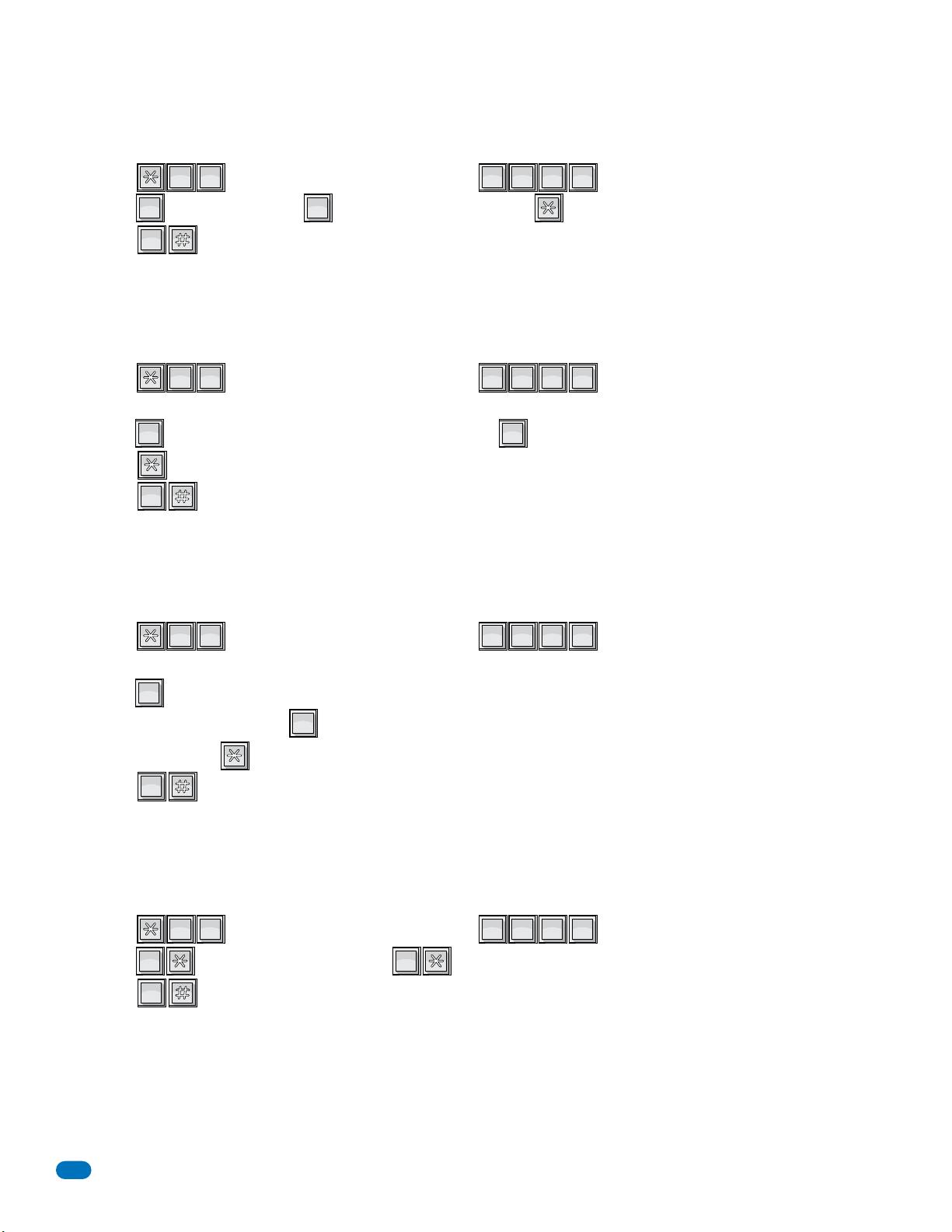
3.2.6 RS-232 Speed Setting
?
5
JKL
8
TUV
0
OPER
1
SP
0
OPER
?
8
TUV
1
SP
0
OPER
?
5
JKL
7
PQRS
0
OPER
1
SP
1
SP
0
OPER
0
OPER
?
4
GHI
0
OPER
0
OPER
1
SP
0
OPER
The following programming sequence sets an optional faster RS-232 speed. This feature is available on Rev M boards or higher
and the Remote Account Manager Software, Version 6.3.b, must be used.
Factory setting = 0 (9600 baud rate)
TUV
1. Press and enter your four-digit MASTER CODE (beep).
2. Enter for 9600 baud rate or for 19200 baud rate, then press (beep).
3. Press together to end this programming sequence (beeeeeep).
3.2.7 Switch Input Feature
The following programming sequence sets the switch input (main terminals #4 and #6) to either activate a relay(s) or call the
phone number programmed in directory code 0, 00, 000 or 0000. Refer to section 3.3.4 to determine which relay(s) will activate
OPER
0
OPER
0
JKL
8
5
SP
1
???????
when the switch input is activated. This feature is available on Rev K boards or higher.
Factory setting = 0 (switch input activates relay)
SP
1. Press and enter your four-digit MASTER CODE (beep).
TUV
1
8
???????
The LCD display on the 1834, 1835 and 1837 systems will read: KEY IN DIAL? 0=N 1=Y
2. Enter for YES (the switch input will dial a phone number) or for NO (the switch input will activate the relay), then
press (beep).
3. Press together to end this programming sequence (beeeeeep).
SP
1
OPER
0
OPER
0
3.2.8 Elevator Control Feature
This new elevator feature authorizes floor access to the Floor Level identified in the Resident Screen in the software program AND
to the floor(s) level identified in the Security Level screen. If this feature is turned off, access will be granted only the floor
identified in the user’s security level. This feature is available on Rev K boards or higher. This feature is NOT available for the 1834.
Factory setting = 1 (new elevator function is turned ON)
PQRS
1. Press and enter your four-digit MASTER CODE (beep).
JKL
7
5
The LCD display on the 1835 and 1837 systems will read: NEW EL FUNC? 0=N 1=Y
2. Enter for YES (access is authorized to both the floor identified in the resident screen and to the floor(s) identified
in the user’s security level) OR for NO (access is authorized only to the floor(s) identified in the security level
SP
1
OPER
0
???????
screen), then press (beep).
3. Press together to end this programming sequence (beeeeeep).
OPER
0
3.2.9 Single or Multiple Systems
This program sequence sets the telephone entry system to operate as a single unit on the phone line, or to share the phone line
with other units. If multiple systems are sharing the same phone line, then each one must be set as a "multiple system" and
each must have a unique master code.
Factory setting = Single System.
OPER
1. Press and enter your four-digit MASTER CODE (beep).
2. Press (beep) for a single system, OR (beep) for multiple systems.
3. Press together to end this programming sequence (beeeeeep).
STOP!! If the telephone entry system is to be programmed from a PC, NO other programming is required at the system
itself. Refer to the Remote Account Manager for Windows Software help screens for additional programming information.
Continue with the remaining sections in this chapter if the telephone entry system will be programmed by any other method. If
OPER
0
OPER
0
GHI
0
4
SP
1
the factory setting matches your need, there is no reason to reprogram that section.
Remember that advanced features like relay hold open time zones, security levels, and elevator control functions can ONLY be
programmed from the Remote Account Manager Software. If any of these advanced features are being used, DO NOT proceed
with any other programming steps in this manual.
28
???????
1835-065-E-7-13
Page 31
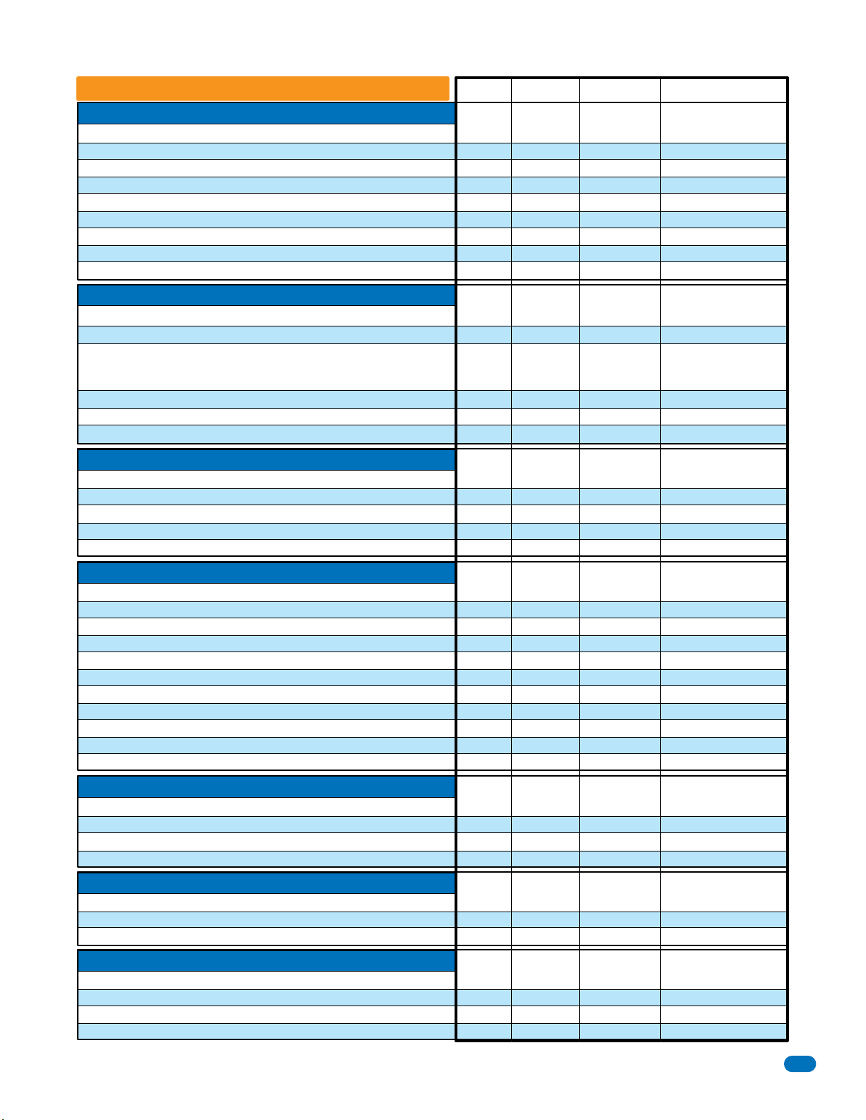
Overview for System Keypad Programming
Section 3.2 Setup Entry System for PC Programming
Master Code
Number of Area Codes Allowed
Call-Up Operation, Interfacing with DKS 1816 or 1820 Systems Only
Resident Elevator Button Relay Time
Open Tone ON or OFF
RS-232 Speed Setting
Switch Input Feature
Elevator Control Feature
Single or Multiple Systems
Section 3.3 General Programming using System Keypad
Relay Strike Time
Talk Time
Tone Open Numbers
Switch Input Relay(s) Activation
Touch-tone / Rotary-dial
Rotary Dial-9 Relay(s) Activation
Section 3.4 Programming Letters, Numbers and Messages
Programming Letters and Numbers from Keypad
Programming the User Message - 1834, 1835 Systems
Programming the Instruction Message - 1834, 1835 Systems
Programming the User Message - 1837 Systems
Programming the Instruction Message - 1837 Systems
Section 3.5 Programming Phone Numbers and Names
Programming the Directory Code Length
Programming Directory Code AND 7-Digit Phone Numbers - No Area Code
Programming Area Codes
Programming Phone Numbers that need Area Codes
Programming Names - 1834, 1835, 1837 Systems Only
Deleting Individual Phone Numbers
Delete Names - 1834, 1835, 1837 Systems Only
Delete Area Codes
Display Phone Numbers - 1834, 1835, 1837 Systems Only
PBX Line Access Code Programming
Touch-Tone Dialing Pause
Section 3.6 Programming Device Codes - 1833, 1835, 1837 Only
Programming Five-Digit Device Codes
Delete Device Codes
Enabling Facility Codes
Programming Facility Codes
Section 3.7 Programming Four-Digit Entry Codes
Programming Five-Digit Device Codes
Delete Device Codes
Enabling Facility Codes
Section 3.8 Anti-Pass Back
Programming the Anti-Pass Back Mode
Re-Sync All Devices
Re-Sync Individual Devices
Reset Facility Counter
Page # Factory Setting
Section Command
26
27
27
27
27
28
28
28
28
30
30
31
31
32
32
33
34
35
36
37
39
39
40
40
41
41
41
42
42
42
42
43
43
43
43
44
44
44
45
45
45
45
3.2.1
3.2.2
3.2.3
3.2.4
3.2.5
3.2.6
3.2.7
3.2.8
3.2.9
3.3.1
3.3.2
3.3.3
3.3.4
3.3.5
3.3.6
3.4.1
3.4.2
3.4.3
3.4.4
3.4.5
3.5.1
3.5.2
3.5.3
3.5.4
3.5.5
3.5.6
3.5.7
3.5.8
3.5.9
3.5.10
3.5.11
3.6.1
3.6.2
3.6.3
3.6.4
3.7.1
3.7.2
3.7.3
3.8.1
3.8.2
3.8.3
3.8.4
Master
Switch ON
6 0
*
78
*
36
*
15
*
85
*
18
*
75
*
04
*
03
*
08
*
05
*
50
*
07
*
51
*
None
80
*
81
*
80
*
81
*
20
*
01
*
24
*
41
*
66
*
01
*
65
*
24
*
06
*
09
*
27
*
70
*
71
*
72
*
73
*
02
*
02
*
12
*
43
*
45
*
46
*
48
*
No factory setting
0 (10 area codes)
0 (OFF)
007 (7 sec)
1 (tone ON)
0 (9600 Baud)
0 (activates relay)
1 (Turned ON)
Single system
Relay 0: 01 (1 sec)
Relay 1: 01 (1 sec)
Relay 2: 01 (1 sec)
060 (60 sec)
Relay 0: # # # #
Relay 1: 9 8 7 6
Relay 2: 5 4 3 2
010 (relay 1 activates)
Touch-tone
010 (relay 1 activates)
No factory setting
Factory message
Factory message
Factory message
Factory message
Three (3) digits
No factory setting
No factory setting
No factory setting
No factory setting
No factory setting
No factory setting
No factory setting
No Factory setting
No factory setting
1 (Pause ON)
No factory setting
No factory setting
No factory setting
No factory setting
No factory setting
No factory setting
No factory setting
No factory setting
No factory setting
No factory setting
No factory setting
1835-065-E-7-13
29
Page 32
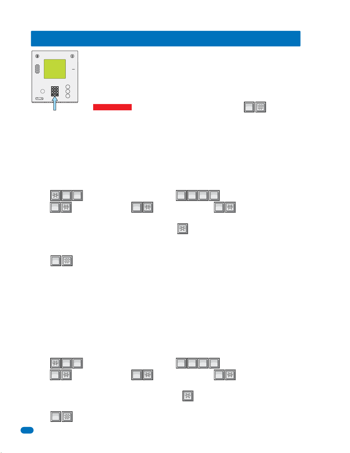
3.3 General Programming Using the System Keypad
9
6
3
0
OPER
WXYZ
TUV
PQRS
MNO
JKL
GHI
DEF
ABCSPSP
?
3
DEF
0
OPER
0
OPER
1
SP
2
ABC
0
OPER
?
8
TUV
0
OPER
0
OPER
1
SP
2
ABC
0
OPER
0
OPER
Proceed with the programming steps on the following pages ONLY IF PC programming WILL NOT be
used. The system keypad may be used to program some features on the telephone entry system but can
be a little tedious to use. We strongly suggest that you become familiar with the programming steps in
A
each feature you want to use BEFORE actually programming the system.
Z
CALL
Important Note: If you make a mistake while programming, press keys at the same time
OPER
0
to escape from programming no matter how much has been completed, then begin again at step 1.
DEF
ABC
11223
MNO
JKL
GHI
44556
WXYZ
TUV
PQRS
77889
OPER
0
System Keypad
3.3.1 Relay Strike Time
These steps will program Relay 0 (relay 0 is not available for the 1834), Relay 1 and Relay 2 strike times. Strike times can be
programmed from 1/4 second up to 99 seconds by entering the desired time in seconds as a two-digit number in step 3. If
Expansion boards are going to be used with this system, set Relay 2 strike time to 00 for Expansion boards 1-8. If more than 8
Expansion boards are being used, set Relay 1 strike time to 00 (for Expansion boards 9-16) and then set Relay 0 strike time for
the desired time in seconds. In this application, Relay 0 becomes the PRIMARY relay that will open the door or gate after the
resident presses 9 on their telephone.
Factory setting for relay strike times are: Relay 0 = 01 (1 sec), Relay 1 = 01 (1 sec), Relay 2 = 01 (1 sec).
OPER
1. Press and enter your four-digit MASTER CODE (beep).
2. Press (beep) to set Relay 0, OR (beep) to set Relay 1, OR (beep) to set Relay 2 strike time.
OPER
0
DEF
0
3
SP
1
???????
ABC
2
Note: “0*” - Relay 0 is not available for the 1834.
3. Enter the two-digit strike time in seconds (00-99), then press (beep).
(Example: 1/4 second - enter 00, 1 second - enter 01 etc.)
4. Repeat steps 2 and 3 to set other relay strike times.
5. Press together to end this programming sequence (beeeeeep).
OPER
0
3.3.2 Talk Time
This programming sequence sets the maximum time allowed for conversation when the entry system places a call to the
resident. The talk time can be set from 1 second up to 255 seconds (4 minutes, 15 seconds) and is entered as a three-digit
number in step 3. The talk time set here DOES NOT affect the telephone numbers that are programmed under directory codes 0,
00, 000, 0000 and 1, 01, 001, 0001. The talk time for these two directory code sets are factory set to the maximum. Phone
numbers programmed under these directory codes should be reserved for management or emergency phone numbers that
generally require longer conversations.
Factory setting for talk time = 060 (60 seconds).
OPER
1. Press and enter your four-digit MASTER CODE (beep).
2. Press (beep) to set Relay 0, OR (beep) to set Relay 1, OR (beep) to set Relay 2 strike time.
OPER
0
TUV
0
8
SP
1
Note: “0*” - Relay 0 is not available for the 1834.
3. Enter the three-digit talk time in seconds (001-255), then press (beep).
(Example: 1 second - enter 001, 20 seconds - enter 020 etc.)
4. Press together to end this programming sequence (beeeeeep).
OPER
0
30
???????
ABC
2
1835-065-E-7-13
Page 33
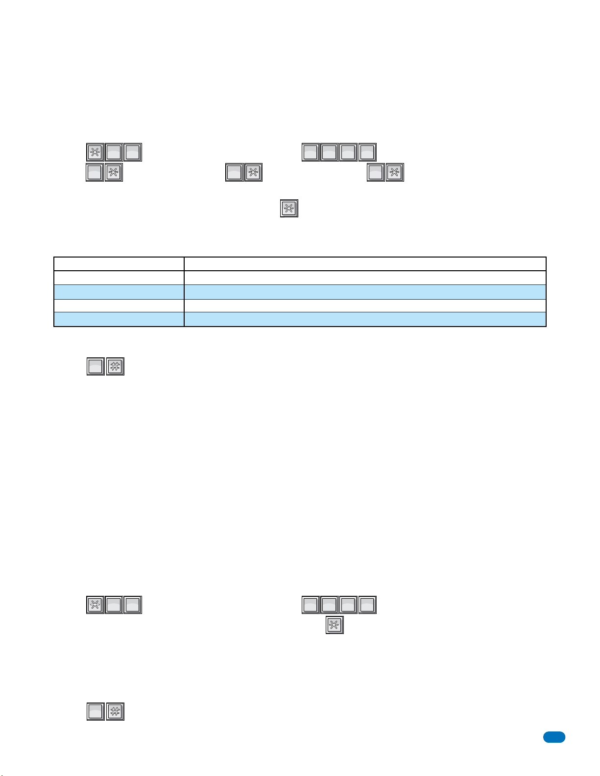
3.3.3 Tone Open Numbers
?
5
OPER
0
JKL
0
OPER
1
SP
2
ABC
0
OPER
?
0
TUV
5
OPER
0
OPER
These steps will program the tone open numbers for Relays 0, 1 and 2. You will need to enter a four-digit number (see chart
below) to set the relay functions. If a function is not desired, enter # in place of a number. If Expansion boards are connected
to the system, there is no need to set a momentary open tone open number for the Expansion control relay(s). However, you
may want to set HOLD and DEACTIVATE tone numbers, which will allow management to have a function to automatically unlock
all doors/gates controlled by a Expansion board (refer to 5.3.2). 1834 only has 2 relays, relay 1 and relay 2.
Factory setting is: Relay 0 = ####, Relay 1 = 9876, Relay 2 = 5432.
JKL
1. Press and enter your four-digit MASTER CODE (beep).
2. Press (beep) to set Relay 0, OR (beep) to set Relay 1, OR (beep) to set Relay 2 tone numbers.
OPER
0
OPER
0
5
SP
1
Note: “0*” - Relay 0 is not available for the 1834.
3. Enter the four-digit tone open number code, then press (beep).
(Example: If you want a relay to have a momentary activation function only, and you want that relay to momentary activate
when the number 9 is pressed, enter 9 # # #. If a function is not desired, enter # in place of a number. Do not duplicate tone
open numbers, Example: don’t set relay 0, 1, and 2 tone-open numbers all to 9.)
4-Digit Tone Open Number Code Function
1st Digit
2nd Digit
3rd Digit
4th Digit
Momentary activation. Relay will activate for the programmed strike time (3.3.1).
Relay hold. Relay will activate and remain activated until commanded to release.
Relay release. Deactivates the relay hold command.
Relay hold 1-hour. Relay will activate for 1-hour and then will automatically deactivate itself.
???????
ABC
2
4. Repeat steps 2 and 3 to set other relay tone open numbers.
5. Press together to end this programming sequence (beeeeeep).
OPER
0
Note: Residents will only be able to activate the Momentary activation when using the entry system.
3.3.4 Switch Input Relay(s) Activation
This programming sequence sets which relay(s) will activate when the switch input (main terminals #4 and #6) is activated on
the telephone entry system. The system can be programmed so that only one relay will activate, or any combination of relays
will activate. TIP: The relay that you designate as the primary relay should be programmed to activate from the postal switch
input. 1833, 1835 and 1837 have 3 relays, relay 0, relay 1 and relay 2. 1834 only has 2 relays (relay 1 and relay 2).
Factory setting = 010 (only relay 1 activates)
OPER
1. Press and enter your four-digit MASTER CODE (beep).
TUV
5
0
2. Enter the three-digit (1's or 0's only) postal relay code, then press (beep).
???????
Three-digit positions: 1st digit position - Relay 0, 2nd digit position - Relay 1, 3rd digit position - Relay 2.
To activate a relay - enter a 1 in a digit position.
To NOT activate a relay - enter a 0 in a digit position.
Example: entering 010 will cause only relay 1 to activate. Entering 101 will cause both relay 0 and relay 2 to activate.
Example for 1834 only: 1st digit position is always 0 because there is no Relay 0.
3. Press together to end this programming sequence (beeeeeep).
1835-065-E-7-13
OPER
0
31
Page 34
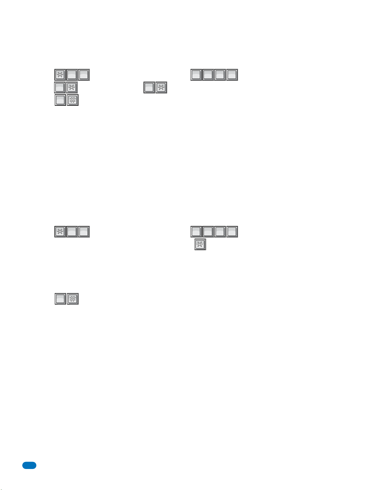
?
1
SP
5
JKL
0
OPER
3.3.5 Touch-Tone / Rotary-Dial
?
7
PQRS
0
OPER
0
OPER
1
SP
0
OPER
This programming sequence will set the telephone entry system to dial out in either a touch-tone or rotary format. Generally,
this will be set for touch-tone.
Factory setting = touch-tone.
OPER
1. Press and enter your four-digit MASTER CODE (beep).
2. Press (beep) for touch-tone, OR (beep) for Rotary
3. Press together to end this programming sequence (beeeeeep).
OPER
OPER
0
0
PQRS
0
7
SP
1
???????
3.3.6 Rotary-Dial 9 Relay(s) Activation
This programming sequence sets which relay(s) will activate when the system receives a rotary-dial 9 open command from a
residents rotary telephone. The system can be programmed so that only one relay will activate, or any combination of relays will
activate. TIP: The relay that you designate as the primary relay should be programmed to activate from a rotary 9 command.
1833, 1835 and 1837 have 3 relays, relay 0, relay 1 and relay 2. 1834 only has 2 relays, relay 1 and relay 2.
Factory setting = 010 (only relay 1 activates)
JKL
1. Press and enter your four-digit MASTER CODE (beep).
SP
5
1
???????
2. Enter the three-digit (1's or 0's only) rotary 9 code, then press (beep).
Three-digit positions: 1st digit position - Relay 0, 2nd digit position - Relay 1, 3rd digit position - Relay 2.
To activate a relay - enter a 1 in a digit position.
To NOT activate a relay - enter a 0 in a digit position.
Example: entering 010 will cause only relay 1 to activate. Entering 101 will cause both relay 0 and relay 2 to activate.
Example for 1834 only: 1st digit position is always 0 because there is no Relay 0.
3. Press together to end this programming sequence (beeeeeep).
OPER
0
32
1835-065-E-7-13
Page 35
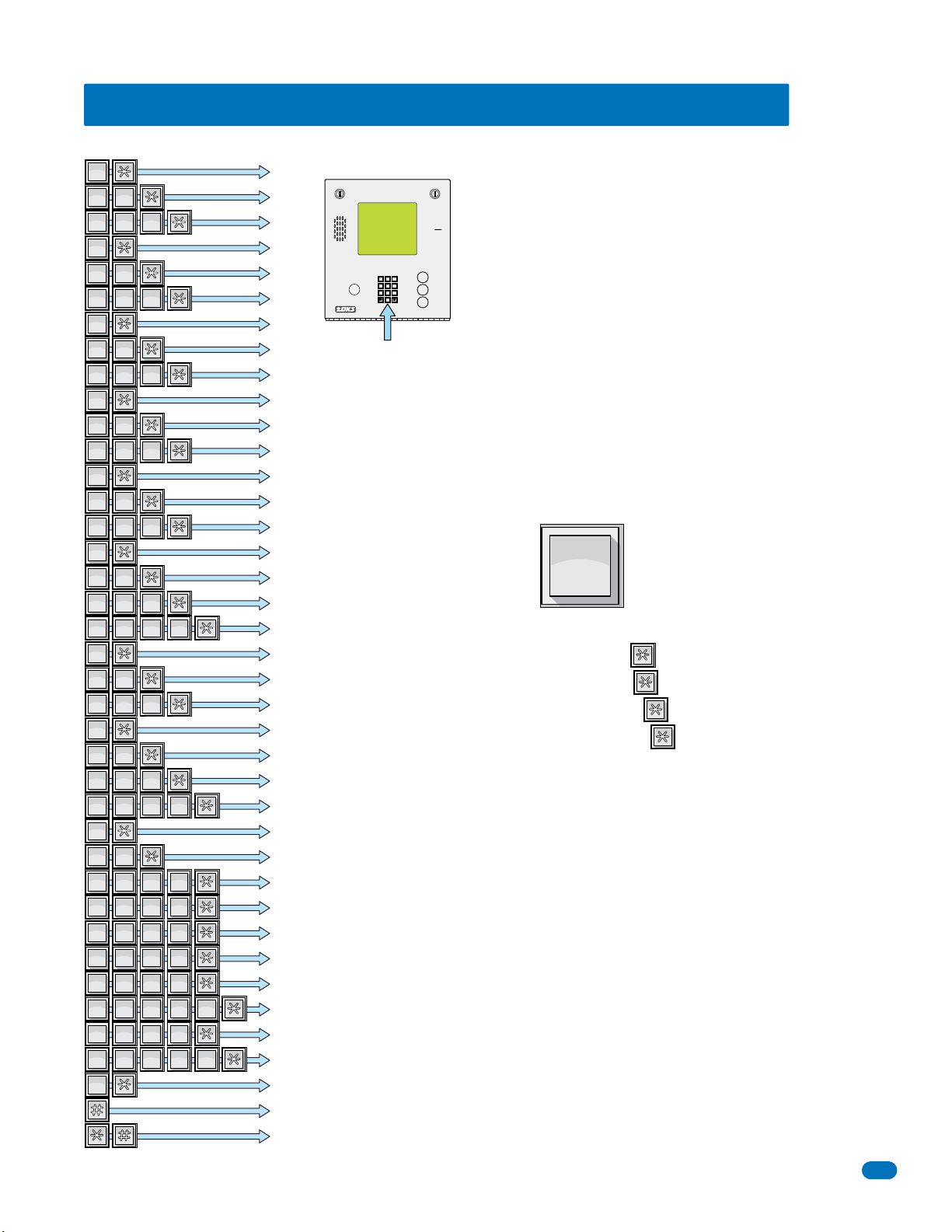
3.4 Programming Letters, Numbers and Messages
6
MNO
1
SP
1
SP
1
SP
2
ABC
2
ABC
2
ABC
2
ABC
2
ABC
2
ABC
2
ABC
2
ABC
2
ABC
2
ABC
3
DEF
3
DEF
3
DEF
3
DEF
3
DEF
3
DEF
3
DEF
3
DEF
3
DEF
3
DEF
4
GHI
4
GHI
4
GHI
4
GHI
4
GHI
4
GHI
4
GHI
4
GHI
4
GHI
4
GHI
5
JKL
5
JKL
5
JKL
5
JKL
5
JKL
5
JKL
5
JKL
5
JKL
5
JKL
5
JKL
6
MNO
6
MNO
6
MNO
6
MNO
6
MNO
6
MNO
6
MNO
6
MNO
6
MNO
6
MNO
7
PQRS
7
PQRS
7
PQRS
7
PQRS
7
PQRS
7
PQRS
7
PQRS
7
PQRS
7
PQRS
7
PQRS
7
PQRS
7
PQRS
7
PQRS
7
PQRS
7
PQRS
8
TUV
8
TUV
8
TUV
8
TUV
8
TUV
8
TUV
8
TUV
8
TUV
8
TUV
8
TUV
9
WXYZ
9
WXYZ
9
WXYZ
9
WXYZ
9
WXYZ
9
WXYZ
9
WXYZ
9
WXYZ
9
WXYZ
9
WXYZ
9
WXYZ
9
WXYZ
9
WXYZ
9
WXYZ
9
WXYZ
0
OPER
9
6
3
0
OPER
WXYZ
TUV
PQRS
MNO
JKL
GHI
DEF
ABCSPSP
1835-065-E-7-13
PQRS
PQRS
PQRS
PQRS
WXYZ
WXYZ
WXYZ
WXYZ
OPER
PQRS
WXYZ
ABC
ABC
ABC
MNO
MNO
MNO
ABC
MNO
...To DisplayPress...
2
ABC
2
2
ABC
2
DEF
3
DEF
3
DEF
3
GHI
4
GHI
4
GHI
4
JKL
5
JKL
5
JKL
5
ABC
2
2
DEF
3
DEF
DEF
3
3
GHI
4
GHI
GHI
4
4
JKL
5
JKL
JKL
5
5
6
MNO
6
6
MNO
6
MNO
6
6
7
PQRS
7
7
PQRS
PQRS
TUV
TUV
PQRS
7
7
PQRS
7
PQRS
7
7
8
TUV
8
8
7
7
TUV
8
TUV
8
TUV
8
9
WXYZ
9
9
WXYZ
WXYZ
WXYZ
9
9
WXYZ
9
WXYZ
9
9
9
9
0
SP
SP
1
1
ABC
ABC
GHI
MNO
PQRS
TUV
WXYZ
ABC
2
2
DEF
DEF
3
3
GHI
4
4
JKL
JKL
5
5
MNO
6
6
PQRS
TUV
WXYZ
PQRS
7
7
8
WXYZ
9
9
7
8
9
2
2
DEF
DEF
3
3
GHI
GHI
4
4
JKL
JKL
5
5
MNO
6
6
PQRS
7
7
TUV
TUV
8
8
WXYZ
9
9
SP
1
A
B
C
D
E
F
G
System Keypad
H
I
J
K
L
M
N
3.4.1 Programming Letters and Numbers from Keypad
When entering names into the electronic directory using the system keypad or a
touch-tone telephone, pressing the key once will display the first letter listed on the
button, pressing twice will display the second letter, pressing it a third time will display
the third letter, and pressing it a fourth time will display the number (or fourth letter).
O
P
Q
R
S
T
U
V
W
Example using the number 6 key:
Press one time to display the letter M, then press to enter it in the system.
Press two times to display the letter N, then press to enter it in the system.
Press three times to display the letter O, then press to enter it in the system.
Press four times to display the number 6, then press to enter it in the system.
X
Y
Z
0
1
2
This chart provides the sequence required to enter each letter and number from the
keypad into the system memory. A sequence is also provided to add a space, clear the
display if a mistake is made, and a sequence to skip a name if there is a desire not to
provide a name with a phone number.
3
4
5
6
7
8
9
Space
Clear
Skip Name
PQRS
11223
GHI
44556
77889
DEF
ABC
MNO
JKL
WXYZ
TUV
OPER
0
These programming steps apply only to the 1834, 1835 and
1837 systems with an LCD display. The keypad on these
telephone entry systems have all the letters of the alphabet, the
numbers 0 through 9, and a space key printed on it. This allows
the keypad to be used to program all names and numbers into the
systems electronic directory.
Note: Names should not be programmed from a remote location
A
Z
using a touch-tone telephone.
CALL
Note: Only upper case letters can be programmed using the
keypad. Upper and lower case letters may be programmed using
the Remote Account Manager Software (PC).
MNO
6
33
Page 36
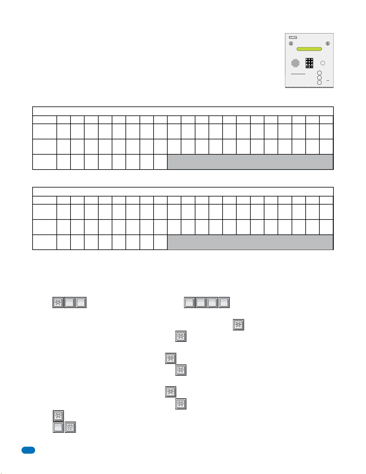
9
6
3
0
OPER
WXYZ
TUV
PQRS
MNO
JKL
GHI
DEF
ABCSPSP
?
0
OPER
8
TUV
0
OPER
3.4.2 Programming the User Message – 1834, 1835 Systems
The user message, followed by the instruction message, scrolls across the screen from right to left
when the system is not in use. Both the user and instruction message can be programmed to display your
own message. The user message can be a maximum of 48 characters (spaces count as a character) and
is entered into the system memory in three blocks. The first two blocks contain 20 characters while the
third block contains 8 characters. The example below shows how the sample message was divided into
three blocks. Use the blank table to organize your own message. Only upper case letters, numbers and
spaces can be programmed from the system keypad.
Factory Default User Message = This Space is For YOUR Scrolling User Programmable Message.
Example: THANK YOU FOR VISITING OAKWOOD CONDOMINIUMS
12345678 9 101112131415161718 19 20
TELEPHONE ENTRY SYSTEM
DEF
ABC
11223
MNO
JKL
GHI
44556
WXYZ
TUV
PQRS
77889
OPER
0
OPERATING INSTRUCTIONS
Use “A to Z” Buttons to Locate
1.
Name and Code Number on Display.
Names are In Alphabetical Order.
To Call, Enter Code Number on
2.
Keypad or Press “Call” Button. If
Line is Busy, Press “#” or “Call” to
Hang Up. Try Again.
Enter on Open Display and Tone.
3.
HOLD TO SCAN
CALL
A
Z
Block 1
Block 2
Block 3
THANK YOU FOR V I S I T I
NG OAKWOOD CONDOMI N I
UMS
Note: The factory default message was programmed from a PC, therefore upper and lower case letters are displayed.
12345678 9 101112131415161718 19 20
Block 1
Block 2
Block 3
After organizing the user message in the table above, follow the instructions below to enter the message into the system. After
each desired letter, number or space is displayed on the directory, remember to press
a character and must be entered into memory as a character. After a complete block of characters (including spaces) has been
to enter that character. Spaces count as
*
entered, press * to enter the block, then start the next block.
TUV
1. Press and enter your four-digit MASTER CODE (beep).
OPER
8
0
???????
The LCD display on the 1834 and 1835 systems will read: BLOCK 1.
2. Enter the characters into block 1 (refer to 3.4.1 for reference). Remember to press (beep) after each character.
3. After the last character in block 1 has been entered, press (beep) to enter the entire block.
The LCD display will read: BLOCK 2.
4. Enter the characters into block 2. Remember to press (beep) after each character.
5. After the last character in block 2 has been entered, press (beep) to enter the entire block.
The LCD display will read: BLOCK 3.
6. Enter the characters into block 3. Remember to press (beep) after each character.
7. After the last character in block 3 has been entered, press (beep) to enter the entire block.
8. Press (beep) to enter all three blocks into the system memory.
9. Press together to end this programming sequence (beeeeeep).
OPER
0
10. The new user message will begin to scroll across the screen.
34
1835-065-E-7-13
Page 37
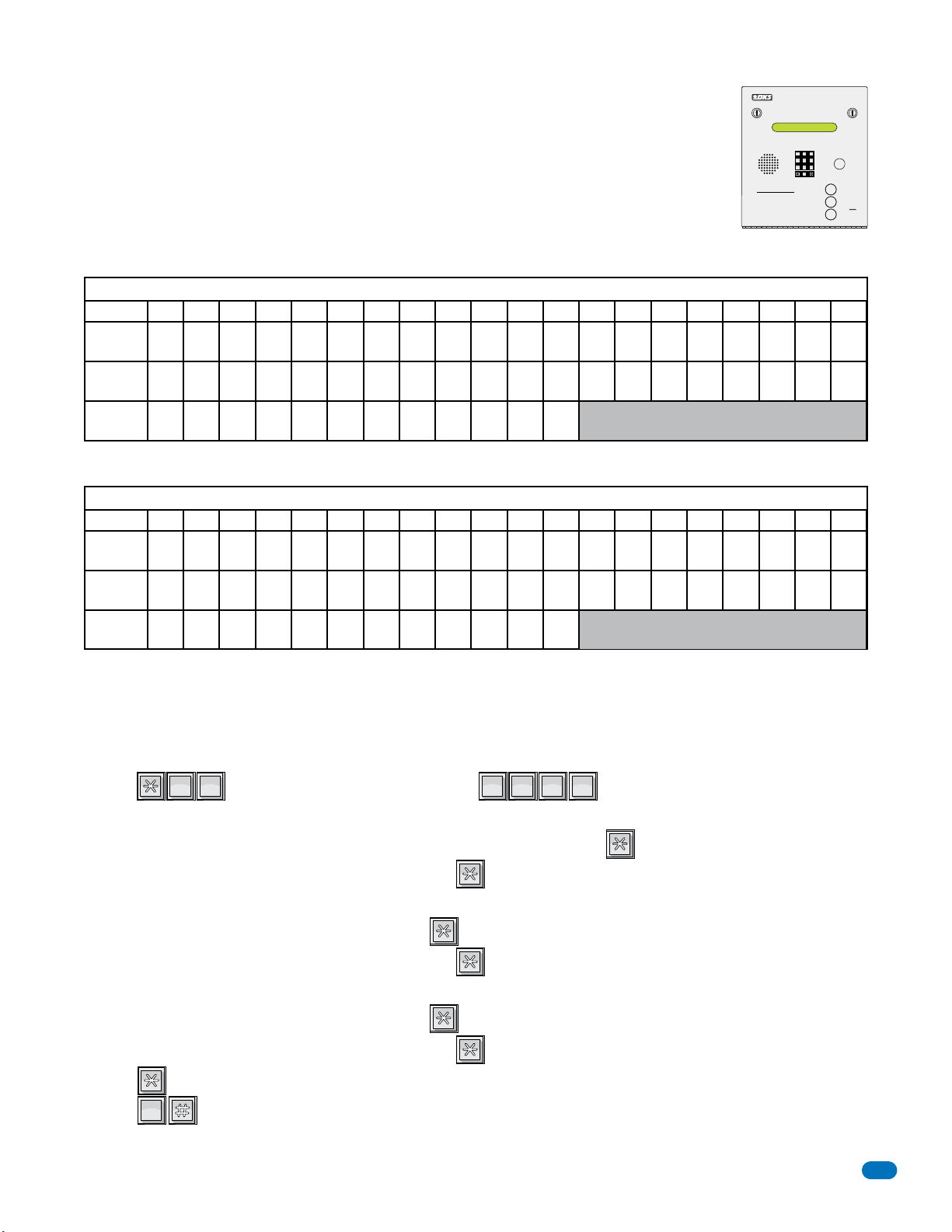
9
6
3
0
OPER
WXYZ
TUV
PQRS
MNO
JKL
GHI
DEF
ABCSPSP
?
1
SP
8
TUV
0
OPER
3.4.3 Programming the Instruction Message – 1834, 1835 Systems
The instruction message scrolls across the screen from right to left when the system is not in use and
follows the user message programmed in 3.4.2. The instruction message can be a maximum of 52
characters (spaces count as a character) and is entered into the system memory in three blocks. The
first two blocks contain 20 characters while the third block contains 12 characters. The example below
shows how the sample instruction message was divided into three blocks and programmed into the
system. Use the blank table to organize your own message. Only upper case letters, numbers and spaces
can be programmed from the system keypad.
Factory Default Instruction Message: Push A-Z To Find Name Or No. Enter Code Or Push Call
Example: PUSH A OR Z BUTTON TO FIND NAME ENTER CODE OR PUSH CALL
12345678 9 101112131415161718 19 20
OPERATING INSTRUCTIONS
Use “A to Z” Buttons to Locate
1.
Name and Code Number on Display.
Names are In Alphabetical Order.
To Call, Enter Code Number on
2.
Keypad or Press “Call” Button. If
Line is Busy, Press “#” or “Call” to
Hang Up. Try Again.
Enter on Open Display and Tone.
3.
TELEPHONE ENTRY SYSTEM
DEF
ABC
11223
MNO
JKL
GHI
44556
WXYZ
TUV
PQRS
77889
OPER
0
HOLD TO SCAN
CALL
A
Z
Block 1
Block 2
Block 3
PUSH A OR Z TO F I ND
NAME ENTER CODE OR P
USH CALL
Note: The factory default message was programmed from a PC, therefore upper and lower case letters are displayed.
12345678 9 101112131415161718 19 20
Block 1
Block 2
Block 3
After organizing the instruction message in the table above, follow the instructions below to enter the message into the system.
After each desired letter, number or space is displayed on the directory, remember to press
count as a character and must be entered into memory as a character. After a complete block of characters (including spaces)
to enter that character. Spaces
*
has been entered, press * to enter the block, then start the next block.
TUV
1. Press and enter your four-digit MASTER CODE (beep).
SP
8
1
???????
The LCD display on the 1834 and 1835 systems will read: BLOCK 1.
2. Enter the characters into block 1 (refer to 3.4.1 for reference). Remember to press (beep) after each character.
3. After the last character in block 1 has been entered, press (beep) to enter the entire block.
The LCD display will read: BLOCK 2.
4. Enter the characters into block 2. Remember to press (beep) after each character.
5. After the last character in block 2 has been entered, press (beep) to enter the entire block.
The LCD display will read: BLOCK 3.
6. Enter the characters into block 3. Remember to press (beep) after each character.
7. After the last character in block 3 has been entered, press (beep) to enter the entire block.
8. Press (beep) to enter all three blocks into the system memory.
9. Press together to end this programming sequence (beeeeeep).
OPER
0
10. The new instruction message will begin to scroll across the screen.
1835-065-E-7-13
35
Page 38
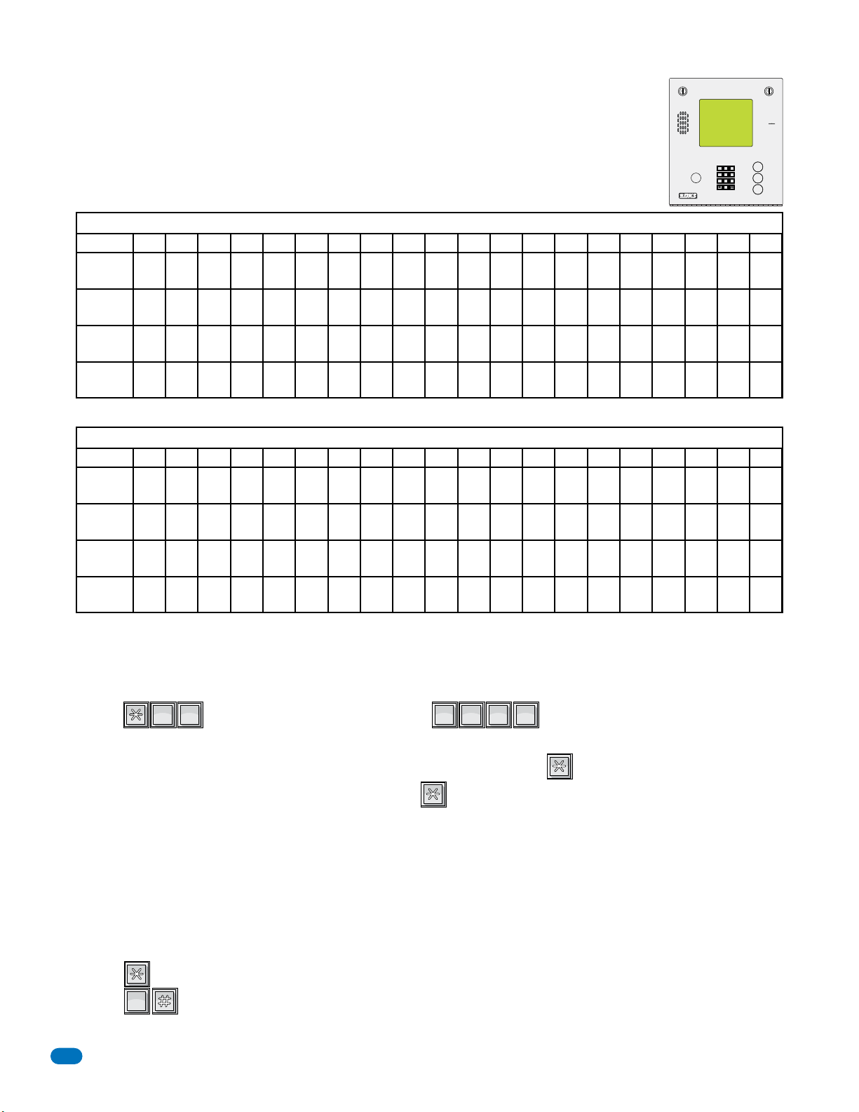
9
6
3
0
OPER
WXYZ
TUV
PQRS
MNO
JKL
GHI
DEF
ABCSPSP
?
0
OPER
8
TUV
0
OPER
3.4.4 Programming the User Message – 1837 System
The user message is displayed on the top four lines of the 1837 display. This message can be a maximum
of 80 characters (spaces count as a character) and is entered into the system memory in four blocks.
The example below shows how the sample message was divided into four blocks and centered on the
screen. Use the blank table to organize your own message. Only upper case letters, numbers and spaces
can be programmed from the system keypad.
Factory Default User Message = This Space is For YOUR Centered User Programmable Message.
11223
GHI
44556
PQRS
77889
DEF
ABC
A
MNO
JKL
WXYZ
TUV
Z
OPER
0
CALL
Example: WELCOME TO THE OAKWOOD CONDOMINIUMS PLEASE DRIVE CAREFULLY
Block 1
Block 2
Block 3
Block 4
12345678 9 101112131415161718 19 20
WE L COME TO T H E
OAKWOOD CONDOMI N I UMS
PLEASE DRIVE
CAREFULLY
Note: The factory default message was programmed from a PC, therefore upper and lower case letters are displayed.
12345678 9 101112131415161718 19 20
Block 1
Block 2
Block 3
Block 4
After organizing the user message in the table above, follow the instructions below to enter the message into the system. After
each desired letter, number or space is displayed on the directory, remember to press
a character and must be entered into memory as a character. After a complete block of characters (including spaces) has been
to enter that character. Spaces count as
*
entered, press * to enter the block, then start the next block.
TUV
1. Press and enter your four-digit MASTER CODE (beep).
OPER
8
0
???????
The LCD display on the 1837 system will read: BLOCK 1.
2. Enter the characters into block 1 (refer to 3.4.1 for reference). Remember to press (beep) after each character.
3. After the last character in the block has been entered, press (beep) to enter the entire block.
The LCD display will read: BLOCK 2.
4. Repeat steps 2 and 3 to enter characters into block 2.
The LCD display will read: BLOCK 3.
5. Repeat steps 2 and 3 to enter characters into block 3.
The LCD display will read: BLOCK 4.
6. Repeat steps 2 and 3 to enter characters into block 4.
7. Press (beep) to enter all four blocks into the system memory.
8. Press together to end this programming sequence (beeeeeep).
OPER
0
9. The new user message will be centered on the screen.
36
1835-065-E-7-13
Page 39
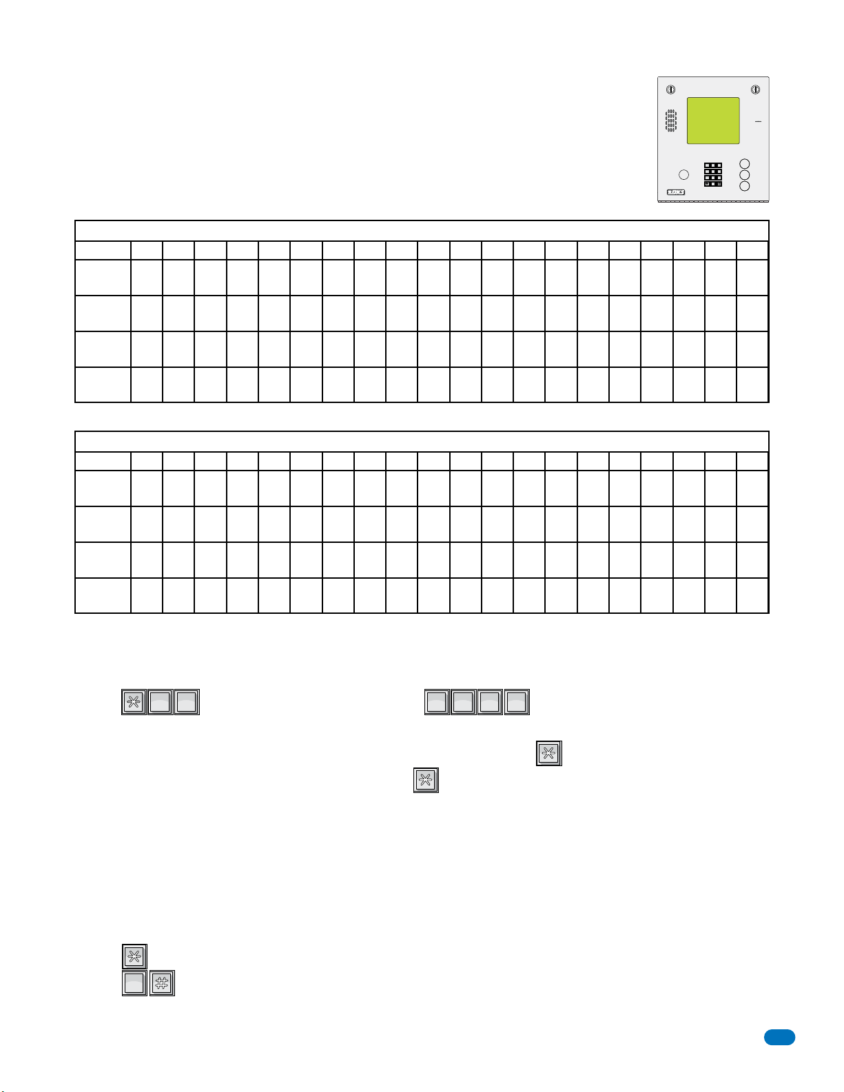
9
6
3
0
OPER
WXYZ
TUV
PQRS
MNO
JKL
GHI
DEF
ABCSPSP
?
1
SP
8
TUV
0
OPER
3.4.5 Programming the Instruction Message – 1837 System
The instruction message is displayed on the bottom four lines of the 1837 display. This message can be a
maximum of 80 characters (spaces count as a character) and is entered into the system memory in four
blocks. The example below shows how the sample message was divided into four blocks and centered on
the screen. Use the blank table to organize your own message. Only upper case letters, numbers and
spaces can be programmed from the system keypad.
Factory Default Instruction Message: Use A-Z to Find Name Or Number - Enter Code On Keypad - Busy
Press Any Key - Try Again.
11223
GHI
44556
PQRS
77889
DEF
ABC
A
MNO
JKL
WXYZ
TUV
Z
OPER
0
CALL
Example: USE A Z TO FIND NAME OR NUMBER ENTER CODE ON KEYPAD BUSY PRESS ANY KEY TRY AGAIN
12345678 9 101112131415161718 19 20
Block 1
Block 2
Block 3
Block 4
USE A Z TO F I ND NAME
OR NUMBER ENTER CODE
ON KEYPAD BUSY PRESS
ANY KEY TRY AGA I N
Note: The factory default message was programmed from a PC, therefore upper and lower case letters are displayed.
12345678 9 101112131415161718 19 20
Block 1
Block 2
Block 3
Block 4
After organizing the instruction message in the table above, follow the instructions below to enter the message into the system.
After each desired letter, number or space is displayed on the directory, remember to press
count as a character and must be entered into memory as a character. After a complete block of characters (including spaces)
to enter that character. Spaces
*
has been entered, press * to enter the block, then start the next block.
TUV
1. Press and enter your four-digit MASTER CODE (beep).
SP
8
1
???????
The LCD display on the 1837 system will read: BLOCK 1.
2. Enter the characters into block 1 (refer to 3.4.1 for reference). Remember to press (beep) after each character.
3. After the last character in the block has been entered, press (beep) to enter the entire block.
The LCD display will read: BLOCK 2.
4. Repeat steps 2 and 3 to enter characters into block 2.
The LCD display will read: BLOCK 3.
5. Repeat steps 2 and 3 to enter characters into block 3.
The LCD display will read: BLOCK 4.
6. Repeat steps 2 and 3 to enter characters into block 4.
7. Press (beep) to enter all four blocks into the system memory.
8. Press together to end this programming sequence (beeeeeep).
OPER
0
9. The new user message will be centered on the screen.
1835-065-E-7-13
37
Page 40
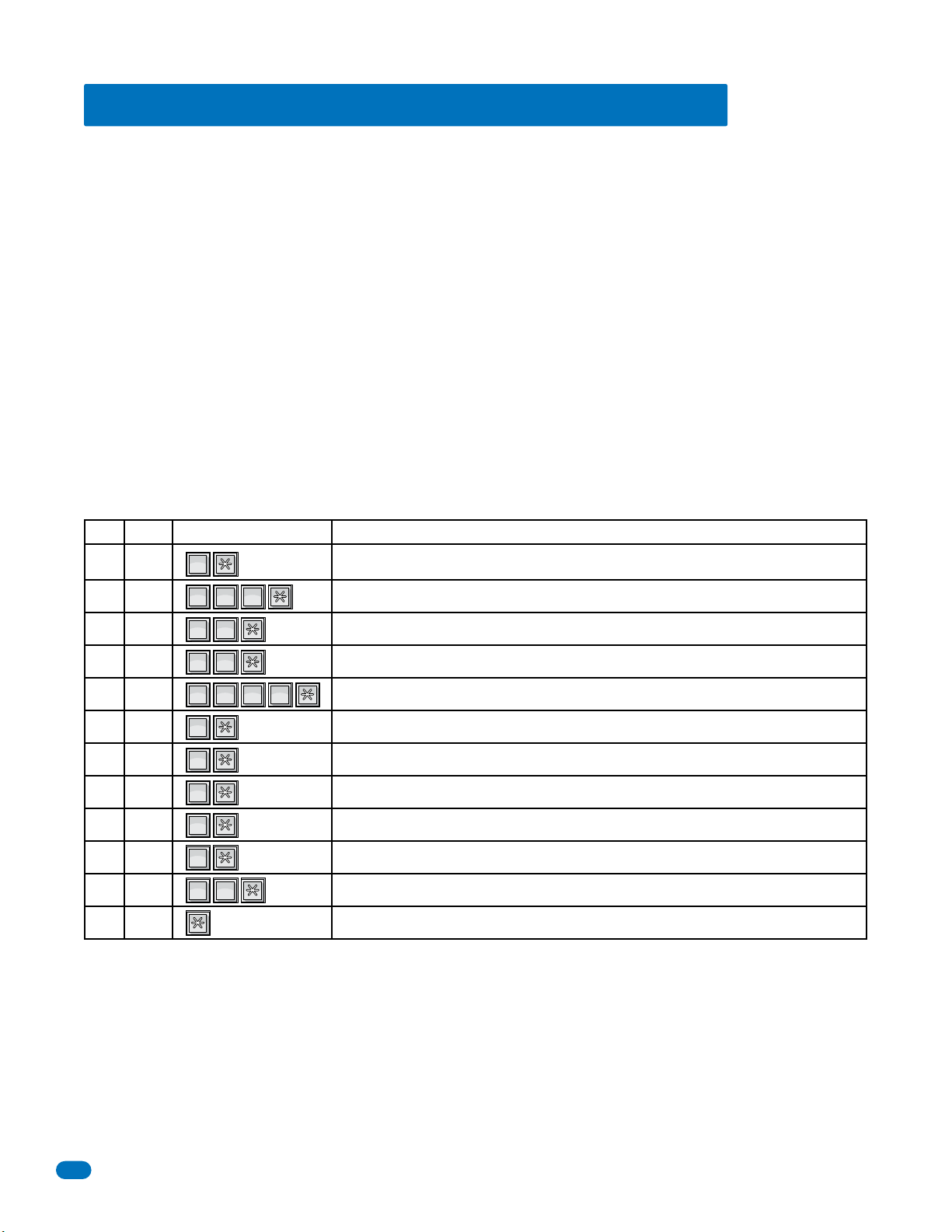
3.5 Programming Phone Numbers and Names
1
SP
1
SP
1
SP
1
SP
2
ABC
3
DEF
3
DEF
5
JKL
6
MNO
6
MNO
6
MNO
6
MNO
6
MNO
7
PQRS
7
PQRS
7
PQRS
7
PQRS
7
PQRS
8
TUV
Before beginning manual programming of phone numbers and names from the system keypad, it is strongly recommended that
the resident log sheets in the back of this manual be competed in their entirety. This will make programming easier and can be
used as a reference when entering phone numbers, names, entry codes and device numbers.
This section of the manual will instruct you on how to enter phone numbers and names into the system memory from the
keypad on the telephone entry system. Prior to entering any information, you will set the directory code digits to the desired
length. Changing the directory code length AFTER programming is complete will delete all programmed phone numbers,
area codes, and names and will require you to re-enter this information.
If you are in an area that requires 10 digit dialing, you will need to program the area code(s) required as described in 3.5.3, and
then program the resident phone numbers as described in 3.5.4. If 10-digit dialing is not required, simply enter the 7-digit
phone number as described in 3.5.2.
1834, 1835 and 1837 systems only. When you are entering names into the electronic directory, remember to press * after each
desired letter, number, or space is displayed on the LCD screen. When the entire name is displayed on the directory, press *
again to enter the entire name into the directory. If you make a mistake, simply press # to clear the display and start over.
Names cannot be more than 15 characters in length - spaces count as a character.
Only upper case letters, numbers, spaces and a clear function (in case you make a mistake) can be programmed from the
system keypad.
Example of programming 12 characters: JONES APT 1
Keypad SequenceDigit Programming Description
JKL
MNO
MNO
MNO
MNO
MNO
DEF
DEF
PQRS
PQRS
PQRS
PQRS
SP
ABC
PQRS
TUV
SP
SP
SP
J
1
O
2
N
3
E
4
S
5
6
A
7
P
8
T
9
10
1
11
12
Note: Refer to 3.4.1 on page 33 to reference how to program each individual letter, number, space, clear etc.
38
Press the 5 key one time to display J, then press the * key to enter the letter.
Press the 6 key three times to display O, then press the * key to enter the letter.
Press the 6 key twice to display N, then press the * key to enter the letter.
Press the 3 key two times to display E, then press the * key to enter the letter.
Press the 7 key four times to display S, then press the * key to enter the letter.
Press the 1 key one time for a space, then press the * key to enter the space.
Press the 2 key one time to display A, then press the * key to enter the letter.
Press the 7 key one time to display P, then press the * key to enter the letter.
Press the 8 key one time to display T, then press the * key to enter the letter.
Press the 1 key one time for a space, then press the * key to enter the space.
Press the 1 key twice to display 1, then press the * key to enter the number.
Press the * key to enter the entire name in the system.
1835-065-E-7-13
Page 41
3.5.1 Programming the Directory Code Length
?
0
OPER
2
ABC
0
OPER
1
SP
?
1
SP
0
OPER
0
OPER
This programming sequence sets the directory code length to 1 - 2 - 3 or 4 digits.
When 10 to 99 resident names or telephone numbers are going to be programmed, the directory code must be at least
two-digits, but can be 3 or 4 digits.
When 100 to 999 resident names or telephone numbers are going to be programmed, the directory code must be at least
three-digits, but can be 4 digits.
When 1000 or more resident names or telephone numbers are going to be programmed, the directory code must be set to
four-digits.
Factory setting is three (3) digits.
CAUTION: This programming sequence will delete ALL phone numbers and
directory codes that have been previously programmed into the system.
ABC
1. Press and enter your four-digit MASTER CODE (beep).
OPER
2
0
???????
The LCD display on the 1834, 1835 and 1837 systems will read: # OF DIRECTORY CODE DIGITS
2. Enter 1, 2, 3 or 4 digits, then press (beep).
The LCD display will read: ERASE MEM? 1=Y 0=N
- If there are 10 to 99 resident names or telephone numbers, directory code must be at least two-digits.
- If there are 100 to 999 resident names or telephone numbers, directory code must be at least three-digits.
- If there are 1000 or more resident names or telephone numbers, the directory code must be set to four-digits.
3. Entering will cancel out of this program if desired (beeeeeep).
Entering will change the directory code length (and erase ALL existing memory).
OPER
SP
0
1
The LCD display will read: ERASING
A long beep will sound when complete (beeeeeep).
Directory code digit length has now been programmed.
3.5.2 Programming Directory Codes with 7-Digit Phone Numbers - NO Area Code
In this programming sequence, the directory codes AND 7-digit phone numbers will be programmed into the system. Be sure
you have programmed the directory code length that you desire as described in 3.5.1 above. Changing the directory code
length after programming the telephone numbers will erase all the numbers and directory codes that have been
programmed. To program phone numbers that will need to use an area code (long distance calls and 10-digit calling), program
them in 3.5.4. If you use directory codes 0, 00, 000, 0000 and/or 1, 01, 001, 0001 remember that the talk time for these
directory codes are factory set to the maximum and cannot be changed. Use these directory codes to program management or
emergency phone numbers, which generally require longer conversation periods.
Note: If this telephone entry system is being used in an area that requires 10-digit phone number dialing, proceed to 3.5.3
and 3.5.4 to program the area code, phone number and directory code.
OPER
1. Press and enter your four-digit MASTER CODE (beep).
SP
0
1
???????
2. Choose and enter a directory code (1, 2, 3 or 4 digits depending on what was programmed in 3.5.1 above), then
press (beep). (You cannot duplicate directory codes)
The LCD display on the 1834, 1835 and 1837 systems will read: PHONE#
3. Enter the seven-digit phone number, then press (beep).
Note: If the number that you are entering in this step is less than seven-digits, enter # in the empty spaces after the digits
have been entered.
For example, if the system is connected to a PBX that requires four-digit extension numbers and you want to enter extension
2217, you would enter this number as 2217###, then press
4. Press together to end this programming sequence (beeeeeep).
1835-065-E-7-13
OPER
0
(beep).
*
39
Page 42
3.5.3 Programming Area Codes
?
4
GHI
2
ABC
?
1
SP
4
GHI
0
OPER
0
OPER
Program area codes when 10-digit or long distance calling is required. “Up to 10” OR “up to 255” area codes can be
programmed depending on how the system was programmed in section 3.2.2.
• Area code pointers set for “up to 10” area codes are referenced 0 – 9 in step 2 (for a total of 10).
• Area code pointers set for “up to 255” area codes are referenced 000 – 254 in step 2A (for a total of 255).
The actual area codes will be entered as a four-digit number (1 + the three digit area code). If area codes are being programmed
to facilitate 10-digit calling requirements, precede the three-digit area code with #.
Note: 255 area codes are available on REV E and higher circuit boards. REV D and lower boards only have 10 area codes.
ABC
1. Press and enter your four-digit MASTER CODE (beep).
GHI
2
4
“Up to 10” programmed, LCD display on the 1834, 1835 and 1837 systems will read: 0 – 9 AAC POINTER
“Up to 255” programmed, LCD display on the 1834, 1835 and 1837 systems will read: 000 – 254 AAC POINTER
2. Enter a single-digit area code pointer (0 – 9 when set for up to 10 area codes), then press (beep).
The LCD display will read: 4 DIGIT AREA CODE
2A.Enter a three-digit area code pointer (000 – 254 when set for up to 255 area codes), then press (beep).
The LCD display will read: 4 DIGIT AREA CODE
3. Enter the four-digit area code, then press (beep).
For long distance calling requirements, enter 1 and the three-digit area code (1 + the three digit area code).
For 10-digit calling requirements, enter # and the three-digit area code (# + the three digit area code).
4. Repeat steps 2 and 3 to enter additional area codes. Remember to use a different area code pointer number for every
additional area code entered. See the reference tables in back of this manual to assist you further.
5. Press together to end this programming sequence (beeeeeep).
OPER
0
???????
3.5.4 Programming
In this section, phone numbers that are referenced to an area code pointer (long distance and 10-digit dialing calls) will be
programmed with the directory code. Be sure that the area code(s) have been programmed as described in the preceding
Directory Codes with
Phone Numbers that use Area Codes
section 3.5.3.
Note: If long distance or 10-digit dialing is NOT required, program the seven-digit telephone numbers in section 3.5.2.
GHI
1. Press and enter your four-digit MASTER CODE (beep).
SP
4
1
???????
The LCD display on the 1834, 1835 and 1837 systems will read: DIRECTORY CODE
2. Choose and enter a directory code (1, 2, 3 or 4 digits depending on what was programmed in 3.5.1), then press (beep).
(You cannot duplicate directory codes)
The LCD display will read: AAC POINTER
3. Enter a single-digit area code pointer (0 – 9 when set for up to 10 area codes), then press (beep).
The LCD display will read: PHONE #
3A.Enter a three-digit area code pointer (000 – 254 when set for up to 255 area codes), then press (beep).
The LCD display will read: PHONE #
4. Enter the seven-digit phone number, then press (beep).
Note: If the number that you are entering in this step is less than seven-digits, enter # in the empty spaces after the digits
have been entered.
For example, if the system is connected to a PBX that requires a four-digit extension numbers and you want to enter
extension 2217, you would enter this number as 2217###, then press *(beep).
5. Repeat steps 2, 3, and 4 to enter additional long distance phone numbers.
6. Press together to end this programming sequence (beeeeeep).
40
OPER
0
1835-065-E-7-13
Page 43
3.5.5 Programming Names - 1834, 1835 and 1837 Systems Only
?
6
MNO
6
MNO
?
1
SP
0
OPER
0
OPER
?
5
JKL
6
MNO
0
OPER
0
OPER
In this section, names will be programmed into the system. Names are referenced to a phone number by entering the directory
code that the person’s phone number has been programmed to.
MNO
1. Press and enter your four-digit MASTER CODE (beep).
MNO
6
6
2. Enter the existing directory code (section 3.5.2 or 3.5.4) that the name will be assigned to (1, 2, 3 or 4 digits, section 3.5.1),
then press (beep).
3. Enter the residents name, one character at a time, press (beep) after each character to enter it. Continue entering
characters, pressing (beep) after each character until all characters have been entered.
The LCD display on the 1834, 1835 and 1837 systems will display each character after * is pressed.
Refer to 3.4.1 and 3.5 for reference to letters, spaces etc.
4. Press (beep) to enter the complete name.
The LCD display will go blank after
has been pressed.
*
3. Repeat steps 2, 3, and 4 to enter additional names.
5. Press together to end this programming sequence (beeeeeep).
OPER
0
???????
3.5.6 Deleting Individual Phone Numbers
This programming sequence is used to delete a single phone number under a known directory code. Proceed to 3.5.7 to delete
the resident name after deleting the phone number.
OPER
1. Press and enter your four-digit MASTER CODE (beep).
SP
0
1
???????
2. Enter the existing directory code (section 3.5.2 or 3.5.4) that the phone number has been assigned to (1, 2, 3 or 4 digits,
section 3.5.1), then press (beep).
3. Press , then press (beep).
4. Repeat steps 2 and 3 to delete additional phone numbers.
5. Press together to end this programming sequence (beeeeeep).
OPER
0
3.5.7 Delete Names - 1834, 1835 and 1837 Systems Only
This programming sequence is used to delete a resident name from the directory. These steps WILL NOT erase the resident
telephone number from the system. Go to section 3.5.6 above to delete the resident telephone number.
MNO
1. Press and enter your four-digit MASTER CODE (beep).
JKL
6
5
???????
2. Use the A and Z buttons to locate the name that is to be erased on the LCD screen, then press (beep).
3. Repeat step 2 to erase additional names.
4. Press together to end this programming sequence (beeeeeep).
1835-065-E-7-13
OPER
0
41
Page 44
3.5.8 Delete Area Codes
?
4
GHI
2
ABC
0
OPER
?
6
MNO
0
OPER
0
OPER
?
9
WXYZ
0
OPER
0
OPER
?
7
PQRS
2
ABC
0
OPER
0
OPER
1
SP
This program sequence deletes area code numbers that have been programmed into the system. Refer to section 3.2.2. for
programming on step 2 or 2A.
ABC
1. Press and enter your four-digit MASTER CODE (beep).
GHI
2
4
???????
“Up to 10” programmed, LCD display on the 1834, 1835 and 1837 systems will read: 0 – 9 AAC POINTER
“Up to 255” programmed, LCD display on the 1834, 1835 and 1837 systems will read: 000 – 254 AAC POINTER
2. Enter the single-digit area code pointer (0 – 9 when set for up to 10 area codes), then press (beep).
The LCD display will read: 4 DIGIT AREA CODE
2A.Enter the three-digit area code pointer (000 – 254 when set for up to 255 area codes), then press (beep).
The LCD display will read: 4 DIGIT AREA CODE
3. Enter , then press (beep).
4. Repeat steps 2 or 2A and 3 to delete additional area codes.
5. Press together to end this programming sequence (beeeeeep).
OPER
0
3.5.9 Display Phone Numbers - 1834, 1835 and 1837 Systems Only
Use this programming sequence to display phone numbers programmed under known directory codes, i.e. if you wanted to see
what phone number was programmed under directory code 271. This programming sequence WILL NOT allow you to delete the
phone numbers that are displayed.
OPER
1. Press and enter your four-digit MASTER CODE (beep).
MNO
0
6
2. Enter the existing directory code (section 3.5.2 or 3.5.4) that the phone number has been assigned to (1, 2, 3 or 4 digits,
section 3.5.1), then press (beep).
The phone number programmed under the directory code that was just entered will be displayed on the LCD screen.
- If C C C C C C C is displayed -
this indicates that NO phone number has been programmed under the entered directory code.
- If the first digit is flashing - this is the area code reference code and indicates that the number displayed is a long distance
or 10-digit number.
3. To display additional phone numbers, press and repeat step 2 or proceed to step 4 to end programming.
4. Press together to end this programming sequence (beeeeeep).
OPER
0
???????
3.5.10 PBX Line Access Code Programming
If the telephone entry system is connected to a PBX telephone system rather than a dedicated C.O. line, you may need to set
the unit to dial a line access code prior to dialing the resident phone number. Typically, the line access code is “9”, but check
with the PBX system administrator to be sure.
OPER
1. Press and enter your four-digit MASTER CODE (beep).
WXYZ
0
9
???????
2. Enter the single-digit line access code number, then press (beep).
OPER
0
3. Press together to end this programming sequence (beeeeeep).
Note: To change a line access number, enter the correct number in step 2. To delete a line access number, enter # in step 2.
3.5.11 Touch-Tone Dialing Pause
During touch-tone dialing, the system (by default) places a 2 second pause after dialing a line access code (9 in a PBX system
for example) and after the area code. For example: 9 (2 second pause) 1310 (2 second pause) 6450023
The 2 second pause can be removed by programming 0 into the steps below. In this example, the system would simply dial out
the line access code (9), area code (1310) and phone number (6450023) without any pauses. 913106450023
Factory setting is 1 (pause ON).
ABC
1. Press and enter your four-digit MASTER CODE (beep).
2. Enter (beep) to turn the pause OFF, or enter (beep) to turn the pause ON.
5. Press together to end this programming sequence (beeeeeep).
42
OPER
0
OPER
0
PQRS
2
7
SP
1
???????
1835-065-E-7-13
Page 45
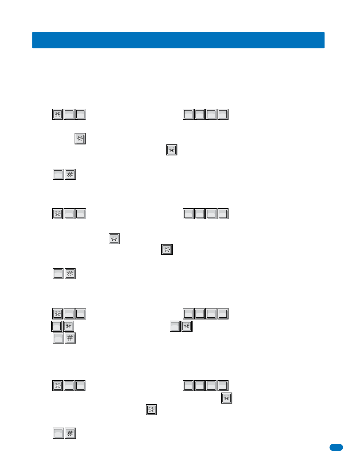
3.6 Programming Device Codes - 1833, 1835, 1837 Only
?
0
OPER
7
PQRS
0
OPER
?
1
SP
7
PQRS
0
OPER
?
2
ABC
7
PQRS
0
OPER
0
OPER
1
SP
?
3
DEF
7
PQRS
0
OPER
Device codes MUST be five (5) digits in length and are typically used for a remote Weigand card reader or transmitter devices.
Each device code that you enter must be assigned to a directory code that you select (that was programmed in section 3.5.2).
Up to 25 device codes can be entered under a single directory code, up to a maximum of 8,000 total device codes for the entry
system. You cannot duplicate device codes.
3.6.1 Programming Five-Digit Device Codes
This program sequence enters device (card, transmitter, digital) codes into the system memory.
PQRS
1. Press and enter your four-digit MASTER CODE (beep).
OPER
7
0
2. Enter the existing directory code (section 3.5.2 or 3.5.4) that the device code will be assigned to (1, 2, 3 or 4 digits, section
3.5.1), then press (beep).
3. Choose and enter a five-digit device code, then press (beep).
4. Repeat steps 2 and 3 to enter additional device codes. (You cannot duplicate device codes)
5. Press together to end this programming sequence (beeeeeep).
OPER
0
3.6.2 Deleting Device Codes
This program sequence deletes individual device codes.
1. Press and enter your four-digit MASTER CODE (beep).
PQRS
SP
7
1
???????
???????
2. Enter the existing directory code (section 3.5.2 or 3.5.4) that the desired device code has been assigned to (1, 2, 3 or 4
digits, section 3.5.1), then press (beep).
3. Enter the desired five-digit device code, then press (beep).
4. Repeat steps 2 and 3 to delete additional desired device codes.
5. Press together to end this programming sequence (beeeeeep).
OPER
0
3.6.3 Enabling Facility Codes
This program sequence allows you to use (enable) or not use (disable) facility codes.
1. Press and enter your four-digit MASTER CODE (beep).
2. Enter (beep) to disable facility codes, or enter (beep) to enable facility codes
3. Press together to end this programming sequence (beeeeeep).
3.6.4 Programming Facility Codes
This program sequence enters device facility codes into the system memory. Up to 10 facility codes (reference numbers 0
through 9) may be programmed. Valid facility codes are 000 – 255.
1. Press and enter your four-digit MASTER CODE (beep).
2. Enter the single-digit first facility code reference number (0 – 9), then press (beep).
OPER
0
OPER
PQRS
ABC
7
2
???????
SP
1
0
PQRS
DEF
7
3
???????
3. Enter the three-digit facility code, then press (beep).
4. Repeat steps 2 and 3 to enter additional facility codes.
5. Press together to end this programming sequence (beeeeeep).
1835-065-E-7-13
OPER
0
43
Page 46
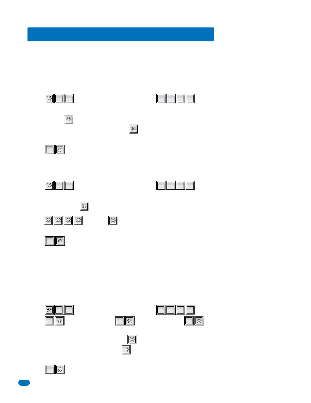
3.7 Programming Four-Digit Entry Codes
?
2
ABC
0
OPER
0
OPER
?
2
ABC
1
SP
0
OPER
0
OPER
1
SP
2
ABC
?
2
ABC
0
OPER
0
OPER
Four-digit entry codes are entered ONLY on the Telephone Entry System Keypad preceded by “ # ” to allow the resident access.
DO NOT confuse a FOUR-digit ENTRY code with a FIVE-digit DEVICE code that is entered on a remote weigand keypad (see
previous page).
Each entry code that you enter must be assigned to a directory code that you select (that was programmed in section 3.5.2).
Only ONE entry code can be programmed for each directory code. You cannot duplicate entry codes.
3.7.1 Programming Four-Digit Entry Codes
OPER
1. Press and enter your four-digit MASTER CODE (beep).
ABC
0
2
2. Enter the existing directory code (section 3.5.2 or 3.5.4) that the entry code will be assigned to (1, 2, 3 or 4 digits, section
3.5.1), then press (beep).
3. Choose and enter a four-digit entry code, press (beep).
4. Repeat steps 2 and 3 to enter additional entry codes. (You cannot duplicate entry codes)
5. Press together to end this programming sequence (beeeeeep).
3.7.2 Delete Entry Codes
1. Press and enter your four-digit MASTER CODE (beep).
OPER
0
OPER
ABC
0
2
???????
???????
2. Enter the existing directory code (section 3.5.2 or 3.5.4) that the desired entry code has been assigned to (1, 2, 3 or 4 digits,
section 3.5.1), then press (beep).
3. Enter , then press (beep).
4. Repeat steps 2 and 3 to delete additional desired entry codes.
5. Press together to end this programming sequence (beeeeeep).
3.7.3 Entry Code Ranges
OPER
0
Four-digit entry codes can be made to activate relay 0, relay 1, or relay 2 or any combination of relays by programming HI and
LOW ranges for each relay. Ranges between relays may overlap, which will cause more than one relay to activate if this is
desired. For example, if the low boundary for relay-0 and relay 1 is 2000, and the hi boundary is 3000 for relay 0 and 4000 for
relay 1, then entry codes between 2000 and 3000 will activate both relays, and entry codes between 3001 and 4000 will only
activate relay 1. 1834 only has 2 relays, relay 1 and relay 2.
SP
1. Press and enter your four-digit MASTER CODE (beep).
2. Press (beep) to set relay 0, or (beep) to set relay 1, or (beep) to set relay 2 boundary.
OPER
0
ABC
1
2
SP
1
???????
ABC
2
Note: “0*” - Relay 0 is not available for the 1834.
3. Enter the four-digit LOW boundary, then press (beep).
4. Enter the four-digit HI boundary, then press (beep).
5. Repeat steps 2, 3, and 4 to set the other relay boundaries.
6. Press together to end this programming sequence (beeeeeep).
44
OPER
0
1835-065-E-7-13
Page 47
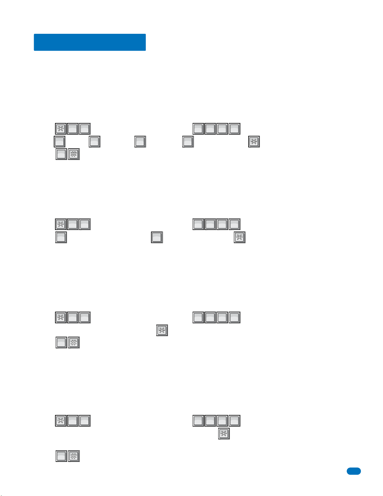
3.8 Anti-Pass Back
?
3
DEF
4
GHI
0
OPER
0
OPER
1
OPER
2
ABC
3
DEF
?
5
JKL
4
GHI
1
OPER
0
OPER
?
6
MNO
4
GHI
0
OPER
?
8
TUV
4
GHI
0
OPER
The programming steps below will allow you to set up and program some basic functions for the anti-pass back feature (APB).
However, you must set up the IN and OUT relay programming table in the Remote Account Manager software. Anti-Pass
Back tables cannot be set from the system keypad. Refer to “Remote account manager for windows” manual 1835-066.
3.8.1 Programming the Anti-Pass Back Mode
Anti-Pass Back (APB) can be set to operate in one of three different modes. PASSIVE APB records an APB Violation and will
allow entry or exit. ACTIVE APB records an APB Violation and will not allow entry or exit. TRAP APB records an APB Violation
and will allow entry but not exit.
GHI
1. Press and enter your four-digit MASTER CODE (beep).
2. Enter for OFF, for PASSIVE, for ACTIVE or for TRAP, then press (beep).
3. Press together to end this programming sequence (beeeeeep).
OPER
0
OPER
0
DEF
4
3
OPER
1
ABC
2
3.8.2 Re-Sync All Devices
This programming step is used to allow all cards one ‘move’ either in or out without causing an APB Violation to be recorded.
GHI
1. Press and enter your four-digit MASTER CODE (beep).
2. Press to Re-Sync ALL devices or press to NOT Re-Sync, then press (beeeeeep).
OPER
1
JKL
4
5
OPER
0
???????
DEF
3
???????
3. The programming sequence will end itself after all cards have been re-synced.
3.8.3 Re-Sync Individual Devices
This programming step is used to re-sync a single card only.
GHI
1. Press and enter your four-digit MASTER CODE (beep).
MNO
4
6
???????
2. Enter the five-digit device number, then press (beep).
OPER
0
3. Press together to end this programming sequence (beeeeeep).
3.8.4 Reset Facility Counter
This programming step is used to reset the facility counter. The facility counter keeps track of the number of “IN’s” and
“OUT’s” when using APB mode.
GHI
1. Press and enter your four-digit MASTER CODE (beep).
TUV
4
8
???????
2. Enter a five-digit number that you want the count to start at, then press (beep).
Example: to start the count at 25, enter 00025.
3. Press together to end this programming sequence (beeeeeep).
1835-065-E-7-13
OPER
0
45
Page 48
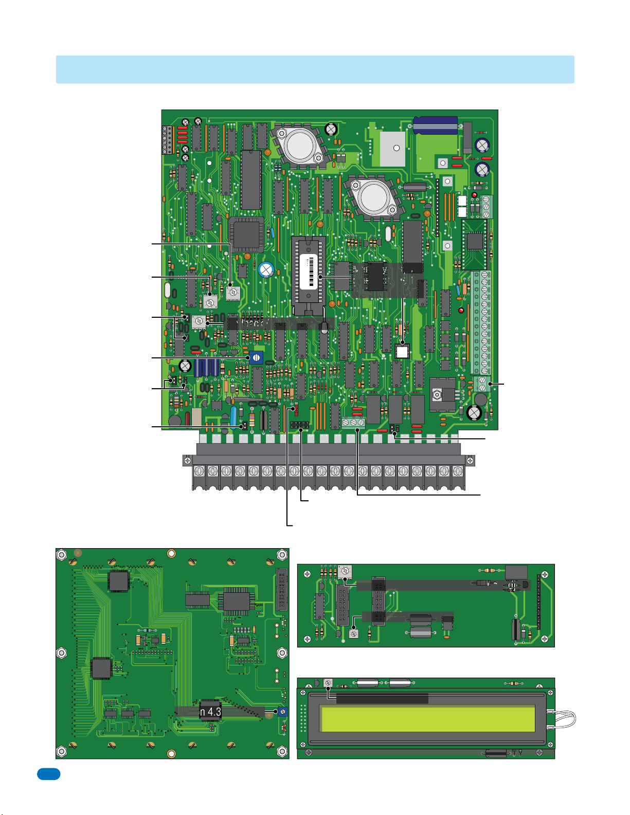
RS-232 Terminal
8 LINE
(see section 2.4.2)
Microphone Volume
(see section 4.1)
Speaker Volume
(see section 4.1)
1816 Interface Jumper
(see section 4.8)
Click Sensitivity
(see section 4.2)
Hands Free (HF) /
Hand Set (HS) Jumper
(see section 4.9)
Ring Pin Jumper
(see sections
3.1 and 4.6)
RS 232
SECTION 4 - ADJUSTMENTS
1830 Series Circuit Board
FEED
BACK
321
1816
HF
HS
Main Terminal (2.2)
sn XX
MIC
VOL
321
321
SPK
VOL
1835
Feedback (see section 4.1)
CLK
SEN
ON
MASTER
CODE
OFF
KEYPAD
RING
5VDCIMDSPKRCOMMICPSWCGNDPHONE
0000010100010
THIS SIDE UP
Memory Chips
(see sections 1.5
and 3.1.3)
NC C
NO
ELEVATOR
1
Elevator Control
2
Terminal
3
1833
1835
1837
(see section 2.1Expansion boards
and elevator
control and 2.2)
Auxiliary Terminal
1833
1835
APB
3000
1837
(see section 2.2)
1212 345 67891011121314
1834 Aux
Terminal Only
(see section 2.2)
RELAY-0
RELAY-2
NO
RELAY-1
NC
Relay 2 Jumper:
Normally Open (NO)
16AC16ACBAT1NO1NC1C2RY2CAZIMC
Normally Closed (NC)
(see section 4.7)
Relay 0 Terminal:
Normally Open (NO)
Normally Closed (NC)
Common (C)
(see section 2.2)
1837 LCD Display Board
Keypad
Connector
Master Code Switch
(see sections 3.2.1 and 4.5)
1834,1835
DOORKING 1892-010
1834, 1835 LCD Display Boards (Surface, Flush)
CONTRAST
CONTRAST
(Wall), 1837 LCD Interface Board
BACKLITE
CUTOFF
321
Backlite Cutoff - Section 4.4 Do not adjust
SINGLE
LINE
DISPLAY
CONTRAST
8 LINE
AY
DISPLAY
Contrast - Section 4.3
DOORKING 1891-010
Contrast - Section 4.3
Section 4.3 - Contrast
DOORKING 1896-012
46
1835-065-E-7-13
Page 49
4.1 Speaker Volume, Microphone and Feedback
Speaker volume, microphone volume and feedback all interact with each other to affect the audio performance of the system.
321
1.
Locate the speaker volume, microphone volume and feedback adjustments on circuit board (see previous page).
SPK
2. Set the speaker volume about 1/3 from full counter-clockwise.
VOL
MIC
VOL
321
FEED
BACK
321
3. Set the microphone volume to 1/2.
4. Place a phone call from the telephone entry system to a resident. If feedback occurs, turn the speaker volume
counter-clockwise until it ceases.
5. While the tenant is still on the line, ask them to remain silent while rubbing your finger over the microphone
hole on the face plate. Rotate the feedback adjustment throughout its range while listening to the sound coming
from the speaker. When the sound is minimum, this is the correct setting.
6. Speaker volume and microphone volume may now be adjusted to desired levels. If both are set too loud,
feedback may result. For louder speaker volume, the microphone volume may need to be decreased. For louder
microphone volume, the speaker volume may need to be decreased.
7. Normal setting for both speaker volume and microphone volume is about 1/2.
8. After setting these adjustments, place some test calls. If feedback occurs, microphone and/or speaker volume
will need to be reduced.
4.2 Click Sensitivity - Use for Rotary-Dial Phones ONLY
1. Locate the click sensitivity adjustment on circuit board (see previous page).
CLK
SEN
2. If rotary dial phones are NOT used, set the click sensitivity to FULL counter-clockwise to disable this feature. If
rotary dial phones are in use, proceed to step 3.
3. Place a phone call from the telephone entry system to a resident with a rotary dial type phone. After they
answer, ask the resident to dial 9 while you adjust the click sensitivity potentiometer (the resident may have to
dial 9 several times for you to obtain the correct adjustment). When the door or gate opens, this is the correct
adjustment for the click sensitivity.
4. Note: Adjusting the click sensitivity too high (potentiometer fully clockwise) could cause the system to respond
to loud noises while it is in use. If this happens, rotate the click sensitivity potentiometer counter clockwise 1/8
turn and re-test the system. You may have to perform this step several times to find the correct adjustment.
4.3 LCD Display Contrast - 1834, 1835 and 1837
31
CONTRAST
or
CONTRAST
31
LCD display is adjusted at the factory and should NOT need to be re-adjusted. If it does, Let the system run for at
least 10-minutes before making any display contrast adjustments.
1. Locate the contrast adjustment on your chosen model (see previous page).
2.
Turn the contrast potentiometer clockwise to lighten, counter-clockwise to darken until the display is satisfactory.
4.4 Backlite Cutoff
321
1835-065-E-7-13
BACKLITE
CUTOFF
This adjustment is only on the 1834/1835 wall mounts and all the 1837 models. This is adjusted at the
factory and should NOT be adjusted in the field.
47
Page 50
4.5 Master Code Switch
The master code switch MUST be kept in the OFF position for normal operation. Turn the master code
ON
MASTER
CODE
OFF
switch ON only when programming the system’s master code. See section 3.2.1 to program the system’s
master code. If the master code switch is turned ON and a new master code is NOT entered, the system will
sound a long tone after approximately 30 seconds. This tone will continue every 30 seconds until a new
master code is entered, or until the switch is turned off.
4.6 Ring Pin Jumper
Always Answer Calls
The ring pin jumper is labeled RING on the control board. This jumper MUST be installed to allow the
system to ALWAYS answer the calls placed to it. If remote programming or remote relay operation is to be
used, the jumper MUST be installed on the pins. Removing the jumper will cause the system to NEVER
RING
Never Answer Calls
RING
answer calls placed to it.
4.7 Relay 2 Jumper
This jumper sets the contacts on relay number two at either Normally Open (NO) or Normally Closed (NC).
The jumper is set to NO from the factory.
NC
NO
4.8 Auto – 1816 Interface Jumper
Auto
1816
This jumper sets the system to operate as a stand-alone unit - AUTO (top position), or to interface with the
1816 Telephone Intercom System (bottom position). The jumper is set to AUTO from the factory.
4.9 HF – HS Jumper
HF
48
For Hands Free (HF) operation, the jumper is set in the left position. For a system with a Hand Set (HS),
the jumper is set in the right position. The jumper is set to HF from the factory.
HS
1835-065-E-7-13
Page 51
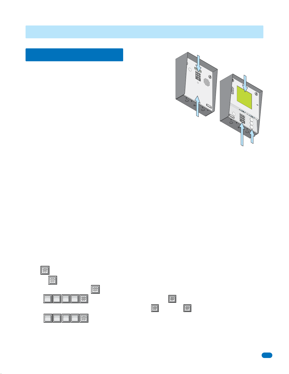
SECTION 5 - SYSTEM OPERATING INSTRUCTIONS
7
8
9
4
5
6
1
2
3
0
O
P
E
R
W
X
Y
Z
T
U
V
P
Q
RS
M
N
O
JK
L
G
HI
D
EF
A
B
C
SP
7
8
9
4
5
6
1
2
3
0
O
P
ER
W
X
Y
Z
T
U
V
P
Q
R
S
M
N
O
J
K
L
G
H
I
D
EF
A
B
C
SP
1
SP
2
ABC
3
DEF
4
GHI
1
SP
2
ABC
3
DEF
4
GHI
System Keypad
5.1 Guest Instructions
TELEPHONE ENTR
Y
S
1833
1.
Locate C
2.
P
r
P
r
3.
Ent
YSTEM
S
P
1
A
B
C
2
D
G
EF
HI
3
4
JKL
5
P
M
Q
N
R
O
S
6
7
T
U
V
8
W
X
Y
Z
9
O
P
E
R
0
O
PE
RAT
es
I
ode Num
NG
s
C
es
ode
I
NST
s
“#”
Nu
ber
e
R
m
r
to
on
ber
U
o
n Ton
CTI
H
D
.
ang
irec
If
O
Line
e
U
.
to
N
P
r
S
.
y.
is
T
r
y
B
A
usy,
gain.
Operating Instructions are printed on most of the telephone entry systems.
The systems with LCD displays have a scrolling or static Instruction Message
on how to operate the system (locating and calling the resident that they wish
to visit). The 1834, 1835 and 1837 systems utilize “A” and “Z” scroll
buttons that a guest will use to locate the resident that they are wishing to
visit. Pushing the “A” button will cause the resident directory to scroll up,
pushing the “Z” button causes the resident directory to scroll down. Holding
these buttons down will cause the system to scroll or page through the
resident directory rapidly. Resident names are listed in the resident directory
alphabetically.
Although the systems are similar in the way that they operate, they differ in the way that the
resident information is presented to the guest. The 1834 and 1835 electronic directory displays
Operating Instructions
resident names (or apartment numbers) and their respective directory code on a single line while the
1837 system displays a page of eight resident names at a time. The 1833 system relies on a separate
printed directory to provide guest with resident directory information.
1. If the guest knows the residents directory code, they can simply enter it on the system keypad to place a call.
2. If the guest does not know the residents directory code, they must check the directory and find the code assigned to the
person they wish to visit.
1833 Systems - Guest must check the separate directory listing to locate the person they wish to visit to find their assigned
directory code. They must then enter this code on the system keypad.
1834, 1835 Systems - Guest use the “A” and “Z” buttons to locate the name in the directory. Once the residents name is
displayed, the guest presses the “CALL” button and the system will connect to the resident’s telephone. The guest may also
enter the directory code on the keypad to place the call.
1837 Systems - Guest use the “A” and “Z” buttons to locate the name in the directory. When the desired resident’s name is
displayed on the page, the “A” and “Z” buttons are used to move the PUSH CALL cursor up and down. When the PUSH CALL
cursor is flashing on the desired resident’s name, the guest then can press the “CALL” button and the system will connect to
the resident’s telephone. The guest may also enter the directory code on the system keypad to place the call.
If the resident’s line is busy, the system will emit a busy signal. If this happens, the guest can press the # key or the “CALL”
button to hang up and then try again. Residents can avoid missing calls from guests at the telephone entry system by ordering
call waiting from the local telephone company.
Instruction Message
Use A
Z to
Or Nu
Find Na
mbe
O
n
r E
me
Ke
nter Code
y
p
ad
An
Bu
y Key
s
y
Press
Tr
1837
y Ag
ain
S
P
1
A
B
C
2
D
G
EF
H
I
3
4
J
K
L
5
P
M
Q
N
R
O
S
6
7
T
U
V
8
A
W
X
Y
Z
9
O
PE
R
0
Z
CALL
Scroll Buttons
System Keypad
DTMF Tones - The telephone entry system can output DTMF tones from the keypad AFTER a call has been answered.
• If the key is pressed by itself – the system will hang-up.
Example: = hang-up.
• If any key is pressed prior to the key, then ALL keys pressed will emit DTMF tones.
SP
Example: = DTMF tones for all buttons including the key.
ABC
1
2
• If there is more than a 2-second delay between numbers and the key, then the key will hang-up the system.
SP
Example: = hang-up.
1835-065-E-7-13
ABC
1
2
GHI
DEF
4
3
GHI
DEF
4
3
49
Page 52

5.2 Resident Instructions
?
Resident control of the door or gate that the telephone entry system controls is limited to opening the door or gate in response
to a call from a guest, or they may open the door or gate by using their assigned four-digit entry code. A resident instruction
sheet is included in the back of this manual and may be copied and passed out to your residents.
5.2.1 Responding to a Guest Call
When communication is established, the resident has the option of opening the door(s) or gate(s) by pressing the
programmed tone open number(s) on their touch tone telephone, or they can deny access to their guest by pressing # on their
telephone. If access is granted, the resident will hear a confirmation tone in their handset indicating that the door or gate has
opened, then the system will automatically hang up.
Residents should be instructed by management to always press the # key on their telephone if they wish to deny a guest
access. If a resident hangs up to deny access instead of pressing #, the telephone entry system will remain on line until its
programmed talk time expires or until it detects dial tone.
Some newer type telephones emit a short tone rather than a continuous tone when their keys are pressed. This may cause the
telephone entry system to not respond to the tone open number. If this happens, simply press the tone open number twice in
rapid succession to open the door or gate.
If a resident is using a rotary dial telephone, they will grant access to their guest by dialing 9. To deny access to their guest,
residents with rotary phones MUST simply hang up.
5.2.2 Using an Entry Code
Four-digit entry codes provide a means for a resident to gain access by entering their assigned code on the telephone entry
system keypad. The four-digit entry code will operate relay 0, 1 or 2 (relay 0 not available for the 1834) depending on the
boundaries that have been programmed into the system (section 3.7.3).
1. To use entry codes, first press and then enter the four-digit entry code .
2. The system will emit a tone (beep) and the LCD display will show OPEN when a valid code is entered on the keypad.
If management decides to utilize resident entry codes, residents should be instructed to keep their unique code secret. Telling
other persons their code or allowing other persons to use their code compromises security and defeats the purpose of the
system.
???????
50
1835-065-E-7-13
Page 53

5.3 System Administrator
The administrator can perform the following operations from a remote location using a touch tone telephone. You must know
the phone number of the system and the system master code. The system MUST be setup to accept incoming calls, see
sections 3.1 and 4.6.
5.3.1 Connecting to the Telephone Entry System from a Remote Location
1.
Call the telephone number that the entry system is installed on. The system will answer with a short tone (beep) after two rings.
2. Press *16 and enter the four-digit MASTER CODE _ _ _ _ (beep). The beep indicates system has accepted master code.
3. Press the desired tone open number _ (beep).
Note: Refer to section 3.3.3 to determine which tone open features have been programmed, i.e. momentary open, hold open,
release, hold open one hour and then release.
4. Hang up.
5.3.2 Expansion Board Override HOLD OPEN Command
The Expansion board override command is used when expansion boards are connected to the system. This command will
cause ALL expansion boards connected to the telephone entry system to OPEN or UNLOCK the gate or door that they are
controlling, and will remain in this state until commanded to return to normal operation. This feature is useful when management wants to open all gates or unlock all doors - perhaps during an emergency situation as an example.
Note: Hold open tone numbers must be programmed for the override command to be functional. See section 3.3.3.
1. Call the telephone number that the entry system is installed on. The system will answer with a short tone (beep).
2. Press *16 and enter the four-digit MASTER CODE _ _ _ _ (beep).
3. Press the hold open tone number that was programmed in section 3.3.3 _ (beep).
4. Hang up.
5. To release the override hold command and return the system to normal operation, repeat steps 1 through 4. In step 3, enter
the DEACTIVATE tone number in place of the HOLD OPEN tone number.
5.3.3 Relay Check
The telephone entry system can be called and a check can be made to determine if any of the relays in the system are in a "hold
open" mode. This check can be useful if your gate (or door) is held open and you suspect that the telephone entry system relay
may be the cause.
1. Call the telephone number that the entry system is installed on. The system will answer with a short tone (beep).
2. Press *16 and enter the four-digit MASTER CODE _ _ _ _ (beep).
3. The system will emit a series of short tones if the relay is in a continuous activation mode:
Relay 1 activated: beep - pause - beep - pause . . .
Relay 2 activated: beep beep - pause - beep beep - pause . . .
Relay 0 activated: beep beep beep - pause - beep beep beep - pause . . .
Note: Relay 0 is Not available for the 1834.
4. Press the programmed tone number _ to deactivate the relay (beep). The system will automatically hang up.
5.3.4 Time and Date Check
This operating functions lets you check the current date, time and day of the week that the system is currently programmed to.
If the calendar chip in the system is NOT programmed, the system will emit a long beeeeeep when this function is entered on
the telephone entry system keypad.
Note: The calendar chip can ONLY be programmed by the PC when communication is established either by modem or the
RS-232 terminal.
1. Press *30 and enter the four-digit MASTER CODE _ _ _ _ (beep).
The LCD display will show: The date - Month / Day / Year
The time - Hours / Minutes / AM or PM (AM=0, PM=1)
The day of the week (1=Sunday, 7=Saturday).
This information will be displayed for approximately four-seconds, then the LCD display will return to normal.
1835-065-E-7-13
51
Page 54

5.4 Miscellaneous Operating Instructions
5.4.1 Talk Time
The talk time for directory codes 0, 00, 000, 0000 and 1, 01, 001, 0001 is factory set to 4 minutes 15 seconds and cannot be
changed. These directory codes should be reserved for use with management or emergency phone numbers that typically
require longer talk times. For example, if directory code 000 was programmed to call a management phone number, the system
will allow the full 4 minutes and 15 seconds of talk time before automatically ending the call.
5.4.2 Telephone Line Sharing
More than one telephone entry system can share the same phone line provided the units have been programmed for multiple
systems on the same line (see section 3.2.9). When the unit is programmed for multiple systems sharing the phone same line,
it checks the phone line for 48 volts (not busy) before attempting to place a call. If the phone line is in use, the system will emit
a busy signal. If two or more systems are sharing the same phone line, it is important that each system be programmed with its
own unique master code. When more than one system is sharing the same phone line, and a call is placed from one of those
systems to a resident, ONLY the system that placed the call will respond to the tone open number that will be sent back to the
unit from the resident’s phone. Other units sharing the same phone line WILL NOT respond to the tone open number sent from
the resident’s phone.
5.4.3 Connection to a PBX System
If the telephone entry system is going to be connected to a PBX system, you may need to program extension numbers in place
of a seven-digit telephone number. To do this, enter the extension number and fill the remaining spaces with the “#” key in the
phone number programming step. For example, if the PBX system uses four-digit extensions, and you want to program
extension 2217 as a phone number in step 3 of section 3.5.2, press: 2 2 1 7 # # # * (beep).
If the PBX system requires you to dial 9 to obtain an outside line, and you want to program some, but not all, outside line phone
numbers in the system, program the number “9” as one of the alternate area codes in step 3 of section 3.5.3:
press: 9 # # # * (beep).
Then program the outside phone number as a long distance number (section 3.5.4) using the area code reference number that
was used to program the number “9”.
5.4.4 Areas with 10-Digit Dialing
If the telephone entry system is installed in an area where the telephone company has instituted 10-digit dialing, simply
program the required number of alternate area codes into the system without preceding the area code with the number 1.
If 310 was one of the area codes required in step 3 of section 3.5.3 press: 3 1 0 # * (beep).
Then program the outside phone number as a long distance number (section 3.5.4) using the area code reference number used
to program 310. Program additional area codes and phone numbers as described in sections 3.5.3 and 3.5.4.
52
1835-065-E-7-13
Page 55
SECTION 6 - MAINTENANCE
The DoorKing telephone entry system is essentially a maintenance free device. When the unit is properly installed, it should
provide years of trouble free service. Maintenance is limited to updating the directory and phone number and/or entry codes
when residents move in or out.
The faceplate of the unit should be cleaned on a regular basis to keep contaminants in the air from sticking to the surface and
possibly causing pitting. When cleaning the faceplate of the system, never use an abrasive cleaner or cloth. Stainless steel
cleaner works very well with a soft cloth for systems with a stainless steel faceplate. A clean damp soft cloth should be used to
clean gold plated faceplates.
6.1 Troubleshooting
If problems should develop with your telephone entry system, refer to the trouble-shooting guide on the following pages to try
and correct any problems. Our experience has shown that a majority of reported problems are actually programming related
and can be corrected on site. If problems persist and they cannot be corrected, contact your authorized DoorKing dealer for
assistance. Before performing any trouble-shooting, check the following:
1. Have a good VOM meter handy to check voltages and continuity.
2. Have a telephone test set (DoorKing P/N 1800-050 or equivalent) to check the telephone line. Noise on the phone line will
cause problems with the entry system.
3. Be sure that the entry system case is properly grounded.
4. Be sure that the telephone wires are twisted.
5. A hum on the system indicates that the phone line or 16.5 VAC power lines may be grounded. Check to be sure that the
phone lines or power lines are not shorted to ground.
6. Check the 16.5 VAC system power. Be sure that the transformer is properly rated (20 VA for 1833, 1834 and 1835 systems;
40 VA for 1837 systems). Keep the wire run from the transformer to the entry system as short as possible. Use 16 or 18 AWG,
600 volt insulated wire only. The importance of proper power wiring cannot be over stressed!
7. Isolate the telephone entry system. Disconnect any external devices, such as expansion boards, elevator control boards, RS
232 connection, card readers, RF receivers, keypads, etc. which may affect the operation of the system.
Symptom Possible Solution(s)
Cannot get into
programming mode.
System emits a long
tone and cancels
programming.
Keypad is dead.
LCD Display shows:
Reset Mem? 1 = Y 2 = N
LCD Display shows:
Need 1835 (3.1.3) SM
MEMCHIP
LCD is unreadable.
• Wrong master code entered. Start over.
• Waiting too long between pushing buttons. Enter information quicker.
• Keypad is not plugged into board correctly. Cable points down.
• Memory chips are installed upside down.
• Waiting too long between pushing buttons.
• Forgetting to press # first when programming.
• No power. Check for 16.5 VAC input power.
• Check that the keypad is properly connected to the circuit board. The cable on the plug
points down when connected to the circuit board.
• The memory chip size (small chip) and the main memory storage ship (large chip) do not
match in memory size. By pressing 1, the main memory storage chip will be matched to the
memory size chip. All data in the main memory will be erased when this function is
performed.
• Press 2 to cancel out of this function.
• The small chip in the PC board socket is for an 1838 system and cannot be used in the
telephone entry system.
• Adjust contrast (4.3).
1835-065-E-7-13
53
Page 56
Symptom Possible Solution(s)
Buzz or noise on the
phone line.
• Disconnect the phone line from the system and check it with a handset. If line is noisy,
problem is with the phone line and not the entry system.
• Check for any shorts to ground behind the circuit board.
• Check for pinched wires near the door hinge.
• Check for 16-volt power shorted to ground.
• Check for phone line shorted to ground.
• Check that phone wires are twisted.
• Check that the proper type of phone wire was used for an outdoor and / or underground
application.
• Check that all wires, speaker, keypad, etc. are isolated from ground.
• Check that the cabinet is properly grounded. Be sure that case ground (terminal 3) is not
used as a low voltage common.
• Check for excessive voltage drop on 16 VAC power.
Ringing or howling
from the speaker.
After dial out, dial
tone is heard on the
speaker.
Door strike locks on.
Door strike or gate
operator holds open.
Entry system will
not answer when
called.
Rotary dial 9 will not
activate relay.
Touch-tone 9 will
not activate relay.
Relay activates but
gate operator will
not open.
Postal switch will
not activate relay.
Four-digit entry
codes will not work.
Entry codes will not
activate relay 0.
Entry codes will not
activate relay 1.
Entry codes will not
activate relay 2.
System emits a beep
every 30 seconds.
DTMF tones are heard 15
seconds after call is
answered.
• Feedback improperly adjusted (4.1).
• Volume is set too high (4.1).
• Phone line is a rotary-dial line. Have the phone company change it to a touch-tone line.
• Excessive voltage-drop on 16 VAC line.
• Using a transformer with too low VA rating.
• Relay strike time programmed too long (3.3.1).
• System was given a hold open command. Call the system and press the tone deactivate
number (5.3.1).
• Ring pin is not installed (4.6).
• Bad phone line or insufficient ring voltage.
• Adjust click sensitivity (4.2).
• Re-program tone-open number to 9 (3.3.3).
• If resident phone emits a short pulse rather than a long tone, press 9 twice in rapid
succession “99”.
• Try another phone that is known to work.
• Lower speaker volume (4.1) and re-adjust feedback (4.1).
• Re-program relay strike time for a longer period (3.3.1).
• Check wiring to gate operator.
• Check gate operator.
• Be sure that the wire-tie has been clipped off the postal switch.
• Be sure that the relay has been programmed for postal switch input (3.3.4).
• Forgetting to press “#” first.
• Re-program the entry code ranges (3.7.3).
• Re-program relay 0 low and high ranges (3.7.3).
• Re-program relay 1 low and high ranges (3.7.3).
• Re-program relay 2 low and high ranges (3.7.3).
• Master code switch is in the ON position (4.5).
• The system CALL-UP feature is turned on. Re-program this feature to turn it off (3.2.3).
54
1835-065-E-7-13
Page 57
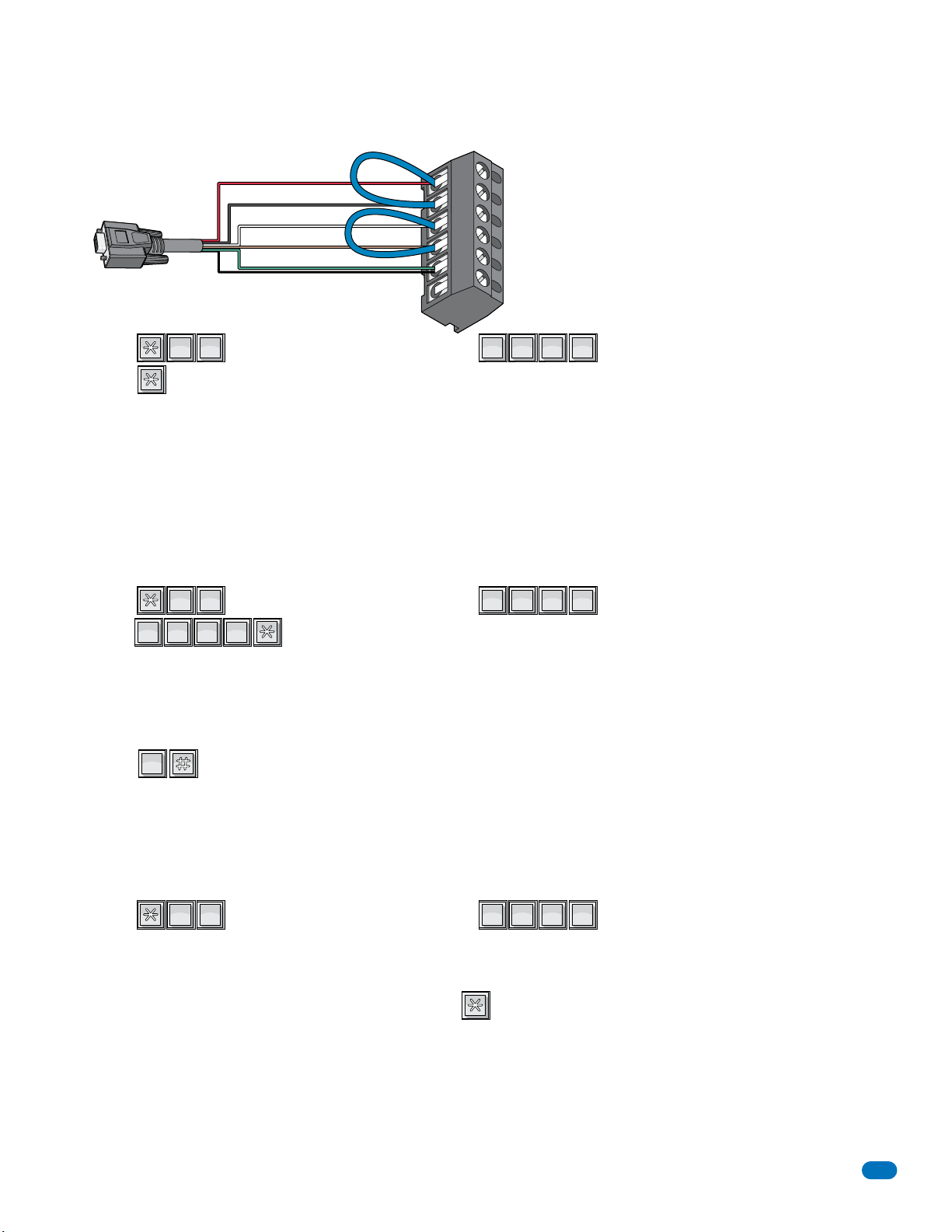
?
7
PQRS
1
SP
6.1.1 RS-232 Test
?
2
ABC
8
TUV
0
OPER
9
WXYZ
9
WXYZ
9
WXYZ
9
WXYZ
?
6
MNO
7
PQRS
This test procedure will check the RS-232 hardware to determine a PASS or FAIL mode. You will need two short pieces of wire
to perform this test (jumpers). Connect the jumper wires as shown to the RS-232 terminal.
1
2
3
4
5
RS-232 Terminal
The 6-pin terminal
can be removed
for easy wiring.
6
RS-232
DB-9 Pin
Plug
Red
Black
White
Brown
Green
Shield
SP
1. Press and enter your four-digit MASTER CODE (beep).
PQRS
1
7
???????
2. Press (beep).
PASS - The LCD display will indicate: RS232 HARDWARE PASS. One long tone will be heard: (Beeeeeep).
FAIL - The LCD display will indicate RS232 HARDWARE FAIL. Two short tones and a long tone will be heard:
(Beep - Beep - Beeeeeep).
3. Remove the jumper wires from the terminal after performing this test.
6.1.2 Weigand Test - 1835 and 1837 Systems Only
This programming sequence will allow you to view the weigand data on the LCD display as it is received by the control board.
This will allow you to verify that the weigand device is functioning properly.
TUV
WXYZ
ABC
8
2
WXYZ
9
WXYZ
9
9
1. Press and enter your four-digit MASTER CODE (beep).
2. Enter .
WXYZ
9
???????
3. Activate one of the weigand input devices by placing a card on a card reader, pressing a transmitter button, or entering a
digital code on a weigand keypad.
4. If the weigand data is shown on the LCD display, this verifies that the weigand device is operating properly and sending the
information to the entry system. If NO data appears on the display, the weigand devices are NOT functioning.
5. Press to cancel the weigand test mode. (beeeeeep).
OPER
0
6.1.3 Elevator Board(s) Hardware Test - 1835 and 1837 Systems Only
This programming sequence is designed for troubleshooting the elevator control board(s) that may be connected to the
telephone entry system. This sequence will take approximately four (4) minutes to complete and will check the operation of the
CALL relay, all the odd numbered relays, then all the even numbered relays on the elevator control board(s). This test confirms
communication between the telephone entry system circuit board and the elevator control board(s).
PQRS
1. Press and enter your four-digit MASTER CODE (beep).
MNO
7
6
2. The LCD display will show: WHICH ELEVATOR?
Note: 0
3. Enter the elevator shaft number (1, 2, 3 or 4) _, then press (beep).
is not available for the 1834.
*
The LCD display will show: ELEVATOR TEST 1.
Once the test starts, the CALL relay (LED ON) will activate, then ALL odd numbered relays will activate. After that, ALL even
numbered relays will activate on the 1st elevator control board. After this sequence, if more than one elevator control board
is connected, ALL odd numbered relays, and then ALL even numbered relays will activate on the 2nd elevator control board.
This sequence will repeat itself up to ten (10) times depending on the number of elevator control boards connected.
???????
4. Once the test is complete (approximately 4 minutes), this programming sequence will automatically end itself.
1835-065-E-7-13
55
Page 58
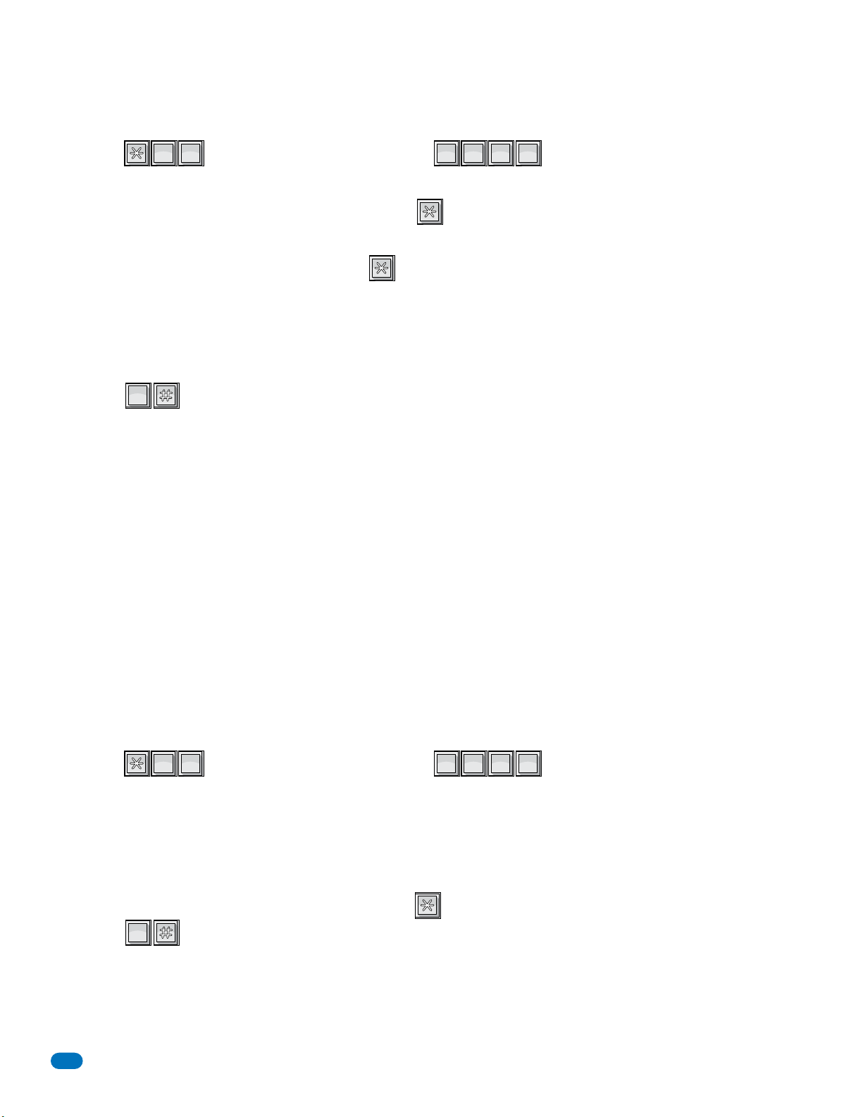
?
7
PQRS
7
PQRS
6.1.4 Elevator Board / Floor Hardware Test - 1835 and 1837 Systems Only
?
0
OPER
4
GHI
0
OPER
0
OPER
This testing sequence will allow you to check activation of individual relays on the elevator control board(s) and will confirm
communication between the telephone entry system circuit board and the elevator control board(s).
PQRS
1. Press and enter your four-digit MASTER CODE (beep).
PQRS
7
7
The LCD display will show: WHICH ELEVATOR?
2. Enter the elevator shaft number (1, 2, 3 or 4) _, then press (beep).
The LCD display will show: FLOOR?
3. Enter the two-digit floor number _ _ , then press (beep).
Note: First floor is entered 01, fifth floor is entered 05 etc.
4. The relay LED on the elevator control board that represents the floor number entered will turn ON for approximately
1 second.
5. To check other floor relays, repeat steps 2 and 3.
6. Press TOGETHER to end this programming sequence (beeeeeep).
OPER
0
Note: This program test sequence will automatically end itself if no keypad inputs are detected after approximately
30 seconds.
Refer to the Elevator Control board installation manual for more information on troubleshooting the elevator control boards.
???????
6.1.5 Automatic Hang-up Options - 1834, 1835 and 1837 Systems Only
This sequence will allow you to program different methods by which the telephone entry system will hang-up if a resident
denies a guest access by hanging up their telephone rather than pressing the “#” key to terminate the call.
Factory setting is 1, dial tone detect ON.
GHI
1. Press and enter your four-digit MASTER CODE (beep).
OPER
4
0
The LCD display will show: 0=N 1=DT 2=SIL 3=BTH.
0 – BOTH OFF. Unit hangs up after programmed strike time runs out.
1 – DIAL TONE detect ON. Unit hangs up after detecting 5-seconds of dial tone.
2 –SILENCE detect ON. Unit hands up after detecting 15-seconds of silence.
3 – BOTH ON.
2. Enter the hang-up option code _ (0, 1, 2 or 3), then press (beep).
OPER
0
3. Press TOGETHER to end this programming sequence (beeeeeep).
???????
56
1835-065-E-7-13
Page 59

6.2 Accessories
Surface Mount Recess Kit
Use to recess a surface mount unit into a wall or column. P/N 1803-150.
Flush Mount Kit
Use to install flush style units into a wall or column. Kit includes rough-in back box and trim-ring. P/N 1814-165 comes with
stainless steel trim ring. P/N 1814-166 comes with gold plated trim ring.
Flush Mount Surface Mounting Kit
Use to surface mount a flush style unit. P/N 1814-152.
Stainless Steel Case
Replaces the black steel surface mount case with a stainless steel case. P/N 1810-102.
Surge Suppressors
Phone line suppressor. P/N 1878-010.
Low voltage (28 V) suppressor. P/N 1878-010.
High voltage (115 V) suppressor. P/N 1879-080.
Mounting Posts
Heavy-duty goose-neck mounting post with mounting plate. P/N 1200-038.
Heavy-duty goose-neck mounting post with concrete base plate for pad mounting. P/N 1200-037.
Designer Style mounting posts; offset P/N 1200-086, straight P/N 1200-085.
Mounting Kiosk, for flush mount units only; P/N 1200-170.
Expansion Board
Expansion boards (P/N 2351-010) allow the 1833, 1835 and 1837 system to operate up to sixteen individual doors or gates,
provides door ajar and forced entry alarms, and can activate local and building alarm systems. Also allows DoorKing gate
operators to report gate operator data and activity to the entry system.
Elevator Board
Elevator control boards (P/N 2348-010) provide control of up to four elevators, with each elevator having a maximum of 64
floors.
RS-232 Cable
RS-232 cable with DB-9 connector on one end and wires on the other end. Use this cable to program the entry system from a
PC using RS-232 communications instead of the modem. P/N 1818-040.
TCP/IP Converter Kit
Enables the 1830 series system to send and receive data via the DKS Internet Server or a LAN. P/N 1830-175.
RS-422 Adapter Kit
Enables the 1830 series system to send and receive data to a PC. P/N 1840-055.
Wireless Adapter
Enables the 1830 series system to send and receive only data (no voice communication) to a PC without a cable connection.
P/N 1815-510 - 1 Remote, 1815-511 - 2 Remotes, 1815-512 - 3 Remotes.
Yagi High-Gain Antenna
Use with the wireless adapter to send and receive data much farther to a PC than the wireless adapter’s antenna. P/N 1815-741.
Telephone Test Set
Includes clips, cord and carrying case. P/N 1800-050.
Battery
12 volt .
8 amp hour gel cell provides stand by power during power interruptions. P/N 1801-008.
1835-065-E-7-13
57
Page 60
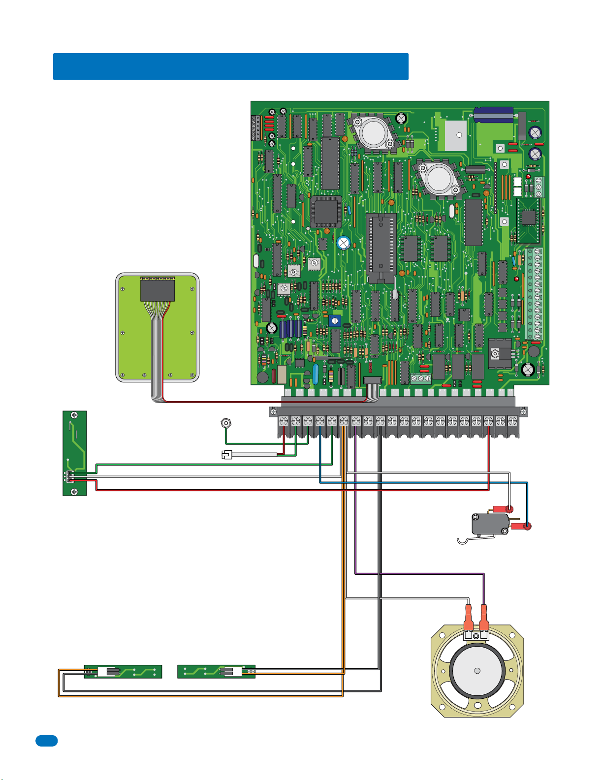
1833 Wiring Schematic: Surface - Flush
Keypad
RS 232
FEED
BACK
321
DOORKING 1833-010
ELEVATOR
1
2
3
MIC
VOL
321
321
SPK
VOL
CLK
SEN
ON
MASTER
CODE
OFF
KEYPAD
RING
P5
RELAY-0
RELAY-2
NO
NC C
NO
RELAY-1
NC
P2
12345 67891011121314
1998-010
Microphone
Green
White
Red
2356-010 2356-010
LED Front Panel Lights (Surface)
Phone Line
Ground
Green
Gray
Orange
Gray
Orange
PSW
COMMIC
SPKR
5VDC
CGNDPHONE
IMD
16AC16ACBAT1NO1NC1C2RY2CAZIMC
White
Blue
Postal Lock
Switch
Purple
White
Speaker
58
1835-065-E-7-13
Page 61
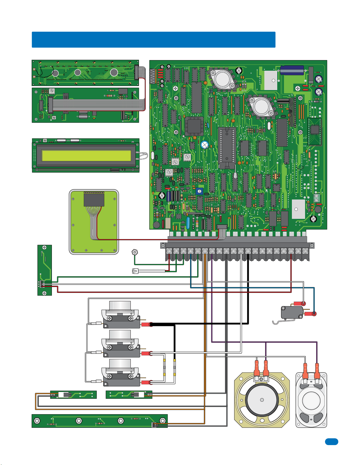
1834 Wiring Schematic: Surface - Flush - Wall
DOORKING 1896-019
BACKLITE
CUTTOFF
321
DOORKING 1892-010
8 LINE
DISPLAY
SINGLE
LINE
DISPLAY
CONTRAST
LCD Display (Wall)
CONTRAST
LCD Display (Surface, Flush)
DOORKING 1891-010
RS 232
FEED
BACK
321
DOORKING 1834-010
LCD Connector
MIC
VOL
321
321
SPK
VOL
CLK
RING
SEN
ON
MASTER
CODE
KEYPAD
OFF
RELAY-2
NO
RELAY-1
NC
P2
1998-010
Keypad
Green
White
Red
Microphone
Note: There is NO Relay
0, Auxiliary Terminal or
Elevator Control on the
1834 circuit board. No
Expansion boards can
be added.
LED Front Panel Lights (Surface)
2342-010
Ground
Phone Line
White
A
Z
CALL
2356-010 2356-010
LED Front Panel Light (Wall)
Green
Black
White
White
Gray
Orange
Gray
Orange
Orange
Gray
PSW
COMMIC
SPKR
5VDC
CGNDPHONE
IMD
16AC16ACBAT1NO1NC1C2RY2CAZIMC
White
Blue
Postal Lock
Switch
Purple
White
Speaker (Surface, Flush)
Speaker (Wall)
1835-065-E-7-13
59
Page 62
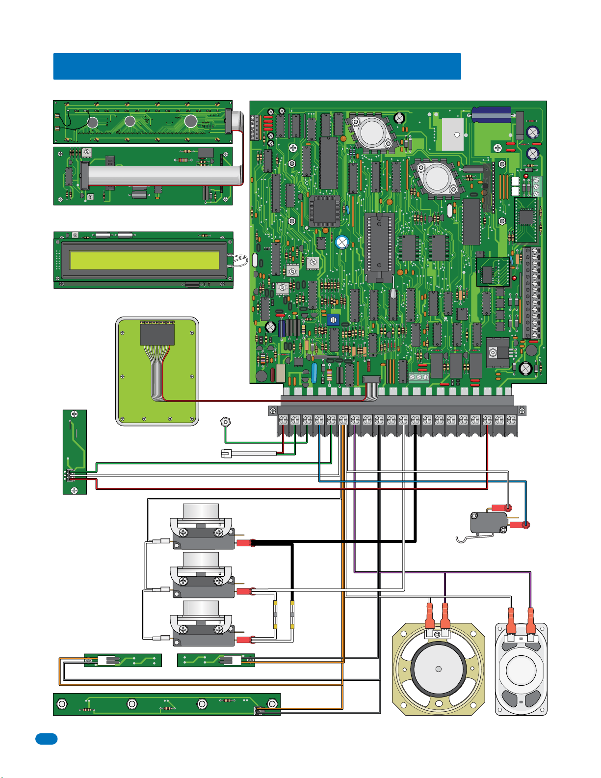
1835 Wiring Schematic: Surface - Flush - Wall
DOORKING 1896-019
BACKLITE
CUTOFF
321
DOORKING 1892-010
8 LINE
DISPLAY
SINGLE
LINE
DISPLAY
CONTRAST
LCD Display (Wall)
CONTRAST
LCD Display (Surface, Flush)
DOORKING 1891-010
RS 232
FEED
BACK
321
DOORKING 1835-010
ELEVATOR
1
2
3
LCD Connector
MIC
VOL
321
321
SPK
VOL
CLK
SEN
ON
MASTER
CODE
OFF
KEYPAD
RING
P5
RELAY-0
NO
NC C
NO
DOORKING
1491-010
RELAY-2
RELAY-1
NC
P2
12345 67891011121314
1998-010
Microphone
2342-010
Keypad
Green
White
Red
White
2356-010 2356-010
LED Front Panel Lights (Surface)
LED Front Panel Light (Wall)
Phone Line
A
Z
CALL
Ground
Green
Black
White
White
Gray
Orange
Gray
Orange
Orange
Gray
PSW
COMMIC
SPKR
5VDC
CGNDPHONE
IMD
16AC16ACBAT1NO1NC1C2RY2CAZIMC
White
Blue
Postal Lock
Switch
Purple
White
Speaker (Surface, Flush)
Speaker (Wall)
60
1835-065-E-7-13
Page 63
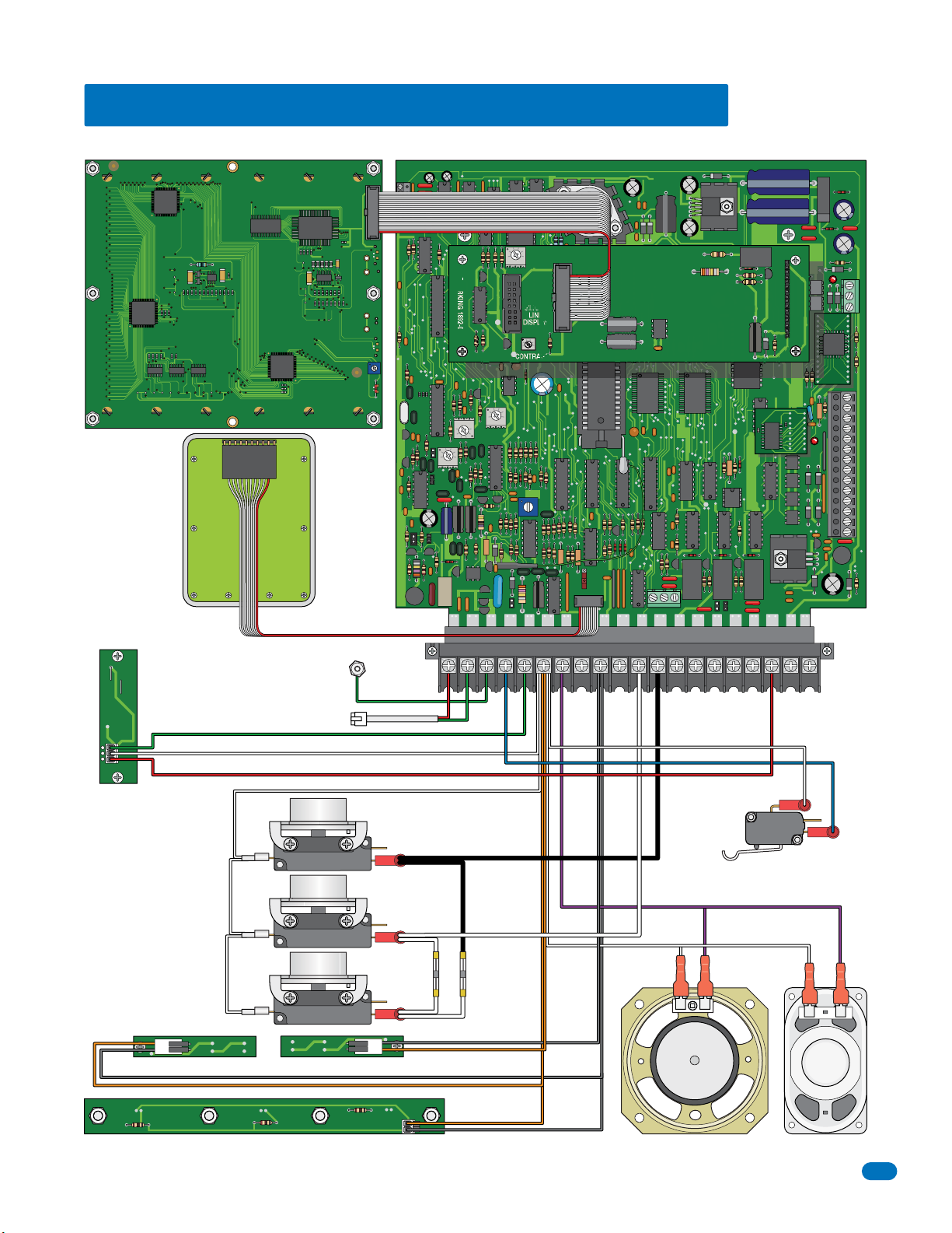
1837 Wiring Schematic: Surface - Flush - Wall
LCD Display
DOORKING 1896-012
Keypad
8 LINE
DISPLAY
KEYPAD
ON
MASTER
CODE
OFF
DOORKING 1837-010
P5
NO
NC C
ELEVATOR
1
2
3
P2
DOORKING
1491-010
12345 67891011121314
RELAY-0
RELAY-2
NO
RELAY-1
NC
RS 232
BACKLITE
CUTOFF
DOORKING 1892-010
CONTRAST
FEED
BACK
321
321
SINGLE
LINE
DISPLAY
CONTRAST
MIC
VOL
321
321
SPK
VOL
CLK
SEN
RING
1998-010
Microphone
2342-010
Green
White
Red
White
2356-010 2356-010
LED Front Panel Lights (Surface)
LED Front Panel Light (Wall)
Phone Line
A
Z
CALL
Ground
Green
Black
White
White
Gray
Orange
Gray
Orange
Orange
Gray
PSW
COMMIC
SPKR
5VDC
CGNDPHONE
IMD
16AC16ACBAT1NO1NC1C2RY2CAZIMC
White
Blue
Postal Lock
Switch
Purple
White
Speaker (Surface, Flush)
Speaker (Wall)
1835-065-E-7-13
61
Page 64
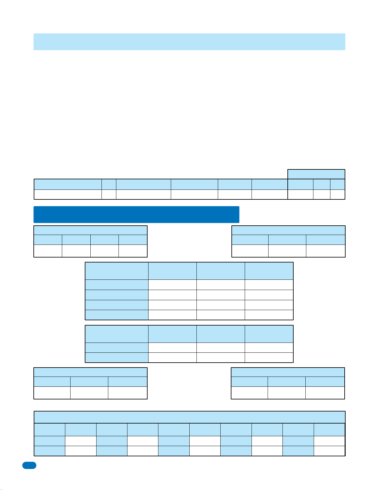
SECTION 7 - LOG TABLES
Complete the information in the tables on the following pages to maintain a record of the information that has been
programmed into the telephone entry system if the system IS NOT being programmed from a PC. If PC programming is being
utilized, there is no reason to maintain these log sheets since the PC will maintain a complete record of the information that has
been programmed.
Make copies of the resident log sheet (pages 65 and 66) so that you have enough to complete a listing of all residents and data.
Enter the information as shown in the example below.
AAC stands for Alternate Area Code. Enter the alternate area code number if alternate area codes have been programmed and
assigned to this resident (section 3.5.3).
DIRECTORY CODE is the resident’s unique directory code. It can be 1 to 4 digits (section 3.5.1).
ENTRY CODE is the resident’s four-digit entry code (section 3.7.1) if they are used.
DEVICE CODE is the resident’s unique device code (section 3.6.1) if access control devices (Transmitters, cards, etc.) are used.
ELEVATOR USE ONLY (Remote Account Manager Software must be used):
SEC LEVEL (Security Level).
FL (Floor).
ER (Elevator Reference Number).
Resident Log Sheet Example
Name
Smith, John 3 765-0000 173 3812 04231 02 14 2
DEVICE CODEENTRY CODEDIRECTORY CODEPHONE NUMBERAAC
ELEVATOR USE
ERFLSEC LEVEL
7.1 Programming Information Tables
Master Code (section 3.2.1)
1st Digit 2nd Digit 3rd Digit 4th Digit
Tone Open Numbers
(section 3.3.3)
Momentary Activation
Relay 0 Note:
Relay 0 is NOT
available on the
Model 1834.
Postal Lock Activates (section 3.3.4)
Relay 0 Relay 1 Relay 2
Relay Hold OPEN
Relay RELEASE
Relay Hold OPEN 1 Hour
Entry Code Ranges
(section 3.7.3)
Low Boundary
High Boundary
7.1.1 10 Area Codes
Area Code Pointers - System Set to 10 Area Codes (section 3.5.3)
Relay Strike Time (section 3.3.1)
Relay 0 Relay 1 Relay 2
Relay 1Relay 0 Relay 2
Relay 1Relay 0 Relay 2
Rotary “9” Activates (section 3.3.6)
Relay 0 Relay 1 Relay 2
Pointer Area Code
1
2
62
Pointer Area Code
3
4
Pointer Area Code
5
6
Pointer Area Code
7
8
Pointer Area Code
9
0
1835-065-E-7-13
Page 65
7.1.2 255 Area Codes - Page 1
Area Code Pointers - System Set to 255 Area Codes (section 3.5.3)
Pointer Area Code Pointer Area Code Pointer Area Code Pointer Area Code Pointer Area Code
001
002
003
004
005
006
007
008
009
010
011
012
013
014
015
016
017
018
019
020
021
022
023
024
025
026
027
028
029
030
031
032
033
034
035
036
037
038
039
040
041
042
043
044
045
046
047
048
049
050
051
052
053
054
055
056
057
058
059
060
061
062
063
064
065
066
067
068
069
070
071
072
073
074
075
076
077
078
079
080
081
082
083
084
085
086
087
088
089
090
091
092
093
094
095
096
097
098
099
100
101
102
103
104
105
106
107
108
109
110
111
112
113
114
115
116
117
118
119
120
121
122
123
124
125
126
127
128
129
130
1835-065-E-7-13
63
Page 66
7.1.2 255 Area Codes - Page 2
Area Code Pointers - System Set to 255 Area Codes (section 3.5.3)
Pointer Area Code Pointer Area Code Pointer Area Code Pointer Area Code Pointer Area Code
131
132
133
134
135
136
137
138
139
140
141
142
143
144
145
146
147
148
149
150
151
152
153
154
155
156
157
158
159
160
161
162
163
164
165
166
167
168
169
170
171
172
173
174
175
176
177
178
179
180
181
182
183
184
185
186
187
188
189
190
191
192
193
194
195
196
197
198
199
200
201
202
203
204
205
206
207
208
209
210
211
212
213
214
215
216
217
218
219
220
221
222
223
224
225
226
227
228
229
230
231
232
233
234
235
236
237
238
239
240
241
242
243
244
245
246
247
248
249
250
251
252
253
254
255
000
64
1835-065-E-7-13
Page 67
7.2 Resident Information
Make additional copies of this table as needed.
Name ERFLSEC LEVEL
ELEVATOR USE
DEVICE CODEENTRY CODEDIRECTORY CODEPHONE NUMBERAAC
1835-065-E-7-13
65
Page 68
7.2 Resident Information
Make additional copies of this table as needed.
Name ERFLSEC LEVEL
ELEVATOR USE
DEVICE CODEENTRY CODEDIRECTORY CODEPHONE NUMBERAAC
66
1835-065-E-7-13
Page 69

A
RESIDENT INSTRUCTIONS
?
Your building / community has been equipped with a DoorKing Telephone Entry System that will provide communication for
your guest from the lobby door / gated entrance to your home by use of the local telephone network. If you have any questions
regarding the use or operation of this system, please see your System Administrator (building manager / HOA representative)
or Call:
Phone #
Guest Communication: Your name (or apartment number) and telephone number have been programmed into
the DoorKing telephone entry system under a specific DIRECTORY CODE. This directory code can be from 1 to 4 digits long.
When a guest comes to visit you, they will look up your name in a resident directory (located on the LCD display or on a
separate printed directory to provide guests with the resident directory information). Your DIRECTORY CODE will be shown next
to your name. Your guest will enter this code on the telephone entry system keypad that will place a call to your home (If your
guest already knows YOUR specific directory code, they can simply enter the code on the keypad without having to look up your
name in the resident directory). Some telephone entry systems are equipped with a “CALL” button. When your name is
displayed on the LCD screen in the resident directory, the guest can press the CALL button to place a call to your home. A guest
CANNOT enter your telephone number on the keypad, it MUST be the DIRECTORY CODE ONLY!
Granting or Denying Access to your Guest: Once you have answered the phone call and you have
identified your guest, you have the choice to either grant access or deny access to your guest.
Touch-Tone Phones ONLY.
To GRANT ACCESS to your guest, press _____ on your touch‐tone telephone. The telephone entry system will respond with a
confirmation tone indicating that the door or gate is opening and will automatically disconnect itself. Some newer telephones
emit a very short duration tone when the number is pressed. If your telephone does this, you may have to press the “GRANT
ACCESS NUMBER” twice in rapid succession to open the door or gate.
To DENY ACCESS to your guest, press the “#” key on your touch‐tone telephone.
Rotary-Dial Phones ONLY.
To GRANT ACCESS to your guest, dial “9”.
To DENY ACCESS to your guest, hang-up your phone.
Call Waiting: If you are on your telephone when a guest tries to contact you from the telephone entry system, they will
hear a busy signal and will have to wait for you to end your call before they can contact you. To eliminate this problem, you can
order call waiting from your local telephone company.
Privacy: If you DO NOT want your name and/or apartment number listed in the electronic resident directory, inform the
system administrator of this. Your telephone number can be stored in the system without your name being displayed on the
directory. If you choose this option, you will need to inform your guest what YOUR directory code is, otherwise there will be
NO WAY for them to identify YOUR directory code on the telephone entry system’s electronic resident directory.
ccess Code: Your system may be equipped with an “access code” that will allow you to open the door / gate by
entering this code on the telephone entry system’s keypad. Your system administrator will advise you of YOUR access code if
this option is available.
To use your access code, first press the key, and then enter your four-digit code .
???????
System Administrator’s Note: Fill in the phone number and access granted number above, copy and distribute this sheet to the residents.
1835-065-E-7-13
67
Page 70

PC Programmable
Installation/Owner’s Manual
Telephone Entry and Access Control Systems
PC Programmable
PC Programmable
1835-065-E-7-13
TM
www.doorking.com
DoorKing, Inc.
120 Glasgow Avenue
UL Listed
68
Inglewood, California 90301
U.S.A.
Phone: 310-645-0023
Fax: 310-641-1586
1835-065-E-7-13
 Loading...