


 Loading...
Owner’s Manual
Model 1808 and 1810 Access Plus Systems
PC Programmable Telephone Entry / Access Control System
DoorKing, Inc. 120 Glasgow Avenue Inglewood, California 90301
U.S.A.
Phone: 310-645-0023 Fax: 310-641-1586
www.doorking.com
P/N 1810-162 REV J, 1/12
Copyright 2009 DoorKing, Inc. All rights reserved.
Page 2 |
1810-162-J-1-12 |
Use this manual with the following models only.
1808 and 1810 Access Plus Telephone Entry / Access Control Systems with circuit board 1970010.
DoorKing, Inc. reserves the right to make changes in the products described in this manual without notice and without obligation of DoorKing, Inc. to notify any persons of any such revisions or changes. Additionally, DoorKing, Inc. makes no representations or warranties with respect to this manual. This manual is copyrighted, all rights reserved. No portion of this manual may be copied, reproduced, translated, or reduced to any electronic medium without prior written consent from DoorKing, Inc.
1810-162-J-1-12 |
Page 3 |
Table of Contents |
|
|
Preface |
|
|
Important Notices...................................................................................................................................................... |
6 |
|
General Information .................................................................................................................................................. |
7 |
|
Features |
.................................................................................................................................................................. |
8 |
Section 1 – Installation & Wiring |
|
|
Installation Guidelines |
|
|
1.1 |
Mount the Access Plus Unit...................................................................................................................... |
9 |
1.2Dimensions
|
Surface Mount 1810 ................................................................................................................................. |
10 |
|
Surface Mount Recess Box 1810 ............................................................................................................. |
11 |
|
Flush Mount Model 1810 .......................................................................................................................... |
12 |
|
Flush Mount Rough-In Box 1810.............................................................................................................. |
13 |
|
Flush Mount Trim Kit 1810 ....................................................................................................................... |
14 |
|
Surface Mount Trim Ring for Flush Mount Unit 1810 ............................................................................... |
15 |
|
Surface Mount 1808 ................................................................................................................................. |
16 |
|
Postal switch Installation .......................................................................................................................... |
17 |
1.3 |
Power Wiring ............................................................................................................................................ |
19 |
1.4 |
Auto-Dialer Wiring Diagram – Single Unit ............................................................................................... |
20 |
1.5 |
Auto-Dialer Wiring Diagram – Multiple Units ............................................................................................ |
21 |
1.6 |
Telephone Intercom Wiring with 1816 AP Module ................................................................................... |
22 |
1.7 |
1816 Access Plus Detail Wiring................................................................................................................ |
23 |
1.8 |
Main Terminal Description........................................................................................................................ |
24 |
1.9Access Plus Interface Board
1.9.1 |
RS-485 Wiring .......................................................................................................................... |
26 |
1.9.2 |
Network Connections ............................................................................................................... |
28 |
1.9.3 |
Modem Connections ................................................................................................................ |
31 |
Section 2 – Programming
2.1 |
Programming the Master Code ................................................................................................................ |
32 |
2.2 |
Programming Methods ............................................................................................................................. |
33 |
2.3Programming with a Computer
|
2.3.1 |
Enable / Disable TCP / IP Support – System Reboot .............................................................. |
34 |
|
2.3.2 |
Set the IP Address ................................................................................................................... |
34 |
|
2.3.3 |
Sub-Net Mask........................................................................................................................... |
35 |
|
2.3.4 |
Set the Gateway (router) IP Address ....................................................................................... |
35 |
|
2.3.5 |
Set the Port Number................................................................................................................. |
35 |
2.4 |
System Parameters – Programming via Keypad / Touch-Tone telephone .............................................. |
36 |
|
|
Programming Reference Table ................................................................................................................ |
37 |
|
|
2.4.1 |
Single or Multiple Units............................................................................................................. |
38 |
|
2.4.2 |
Single or Double Ring .............................................................................................................. |
38 |
|
2.4.3 |
Number of Rings to Residence ................................................................................................ |
39 |
|
2.4.4 |
Talk Time.................................................................................................................................. |
39 |
|
2.4.5 |
Relay Strike Time ..................................................................................................................... |
39 |
|
2.4.6 |
Tone Open Numbers................................................................................................................ |
40 |
|
2.4.7 |
Answer Incoming Calls on X Rings .......................................................................................... |
40 |
|
2.4.8 |
Hang Up Tone .......................................................................................................................... |
41 |
|
2.4.9 |
Call Waiting .............................................................................................................................. |
41 |
|
2.4.10 |
Turn Speaker On...................................................................................................................... |
41 |
|
2.4.11 |
Set Microphone Gain and Speaker Volume ............................................................................. |
42 |
Page 4 |
1810-162-J-1-12 |
2.5Directory Codes
2.5.1 |
Directory Codes 01 – 23 |
1816 Intercom Relay Programming.................................................. |
43 |
2.5.2 |
Directory Codes 24 – 50 |
Dial Phone Number .......................................................................... |
43 |
2.5.3 |
Delete Phone Number from Directory Codes 24 - 50 .............................................................. |
43 |
|
2.5.4 |
Delete All Phone Numbers from Directory Codes 24 - 50........................................................ |
43 |
|
2.6Devices
2.6.1 |
Simple Access Code Programming ......................................................................................... |
44 |
2.6.2 |
Number of RS-485 Devices ..................................................................................................... |
44 |
2.6.3 |
Additional Relay Off-line Function............................................................................................ |
44 |
2.6.4 |
Device Access Code Programming ......................................................................................... |
45 |
2.6.5 |
Delete Device Access Codes................................................................................................... |
45 |
2.6.6 |
Delete All Device Access Codes.............................................................................................. |
45 |
2.6.7 |
Temporary Device Access Code programming ....................................................................... |
46 |
2.6.8 |
Delete Temporary Device Access Codes ................................................................................ |
46 |
2.4.9 |
Delete All Temporary Device Access Codes ........................................................................... |
46 |
2.7Time Functions
2.7.1 |
Program the Calendar Chip ..................................................................................................... |
47 |
2.7.2 |
Relay Hold Schedule................................................................................................................ |
48 |
2.7.3 |
Time Zones .............................................................................................................................. |
49 |
2.8Miscellaneous
2.8.1 |
Restore Defaults ...................................................................................................................... |
50 |
2.8.2 |
Erase Transaction Log ............................................................................................................. |
50 |
Section 3 – Adjustments |
|
|
Speaker Volume and Microphone Gain.................................................................................................................... |
51 |
|
Interface Board LED Status...................................................................................................................................... |
52 |
|
Section 4 – User Instructions
4.1Resident Operating Instructions
4.1.1 |
Granting or Denying a Guest Access....................................................................................... |
53 |
4.1.2 |
Call Waiting .............................................................................................................................. |
53 |
4.1.3 |
Dial-Connect (using 1816 AP module)..................................................................................... |
54 |
4.1.4 |
Dial-Out Phone Numbers ......................................................................................................... |
54 |
4.1.5 |
Access Codes .......................................................................................................................... |
54 |
4.2Remote Operation
4.2.1 |
Remote Programming .............................................................................................................. |
55 |
4.2.2 |
Remote Relay Activation.......................................................................................................... |
55 |
4.2.3 |
Relay Activation Check ............................................................................................................ |
56 |
Section 5 – Maintenance and Trouble Shooting
5.1 |
Trouble Shooting ...................................................................................................................................... |
57 |
5.2 |
Trouble Shooting Tables .......................................................................................................................... |
58 |
5.3 |
Internal Wire Diagram .............................................................................................................................. |
59 |
5.4 |
Accessories .............................................................................................................................................. |
60 |
5.5 |
Programming Information Tables ............................................................................................................. |
61 |
|
Directory Codes / Dial-Out Phone Numbers ............................................................................................ |
62 |
|
Access Code Log Sheet........................................................................................................................... |
64 |
1810-162-J-1-12 |
Page 5 |
Important Notices
FCC – United States
This equipment has been tested and found to comply with the limits for a class A digital device, pursuant to Part 15 of the FCC Rules and Regulations. These limits are designed to provide reasonable protection against harmful interference when the equipment is operated in a commercial environment. This equipment generates, uses, and can radiate radio frequency energy and, if not installed and used in accordance with the instruction manual, may cause harmful interference to radio communications. Operation of this equipment in a residential area is likely to cause harmful interference in which case the user will be required to correct the interference at his own expense.
FCC Registration Number: DUF6VT-12874-OT-T
DOC - Canada
The Canadian Department of Communications label identifies certified equipment. This certification means that the equipment meets certain telecommunications network protective, operational, and safety requirements. The Department does not guarantee the equipment will operate to the users satisfaction.
Before installing this equipment, users should ensure that it is permissible to be connected to the facilities of the local telecommunications company. The equipment must also be installed using an acceptable means of connection. The customer should be aware that compliance with the above conditions may not prevent degradation of service in some situations.
Repairs to certified equipment should be made by an authorized Canadian maintenance facility designated by the supplier. Any repairs or alterations made by the user to this equipment, or equipment malfunctions, may give the telecommunications company cause to request the user to disconnect the equipment.
Users should ensure, for their own protection, that the electrical ground connections of the power utility, telephone lines, and internal metallic water pipe system, if present, are connected together. This precaution may be particularly important in rural areas.
CAUTION: Users should not attempt to make such connections themselves, but should contact the appropriate electric inspection authority, or electrician, as appropriate.
DOC Registration Number: 1736 4507 A
Notice:
The Load Number (LN) assigned to each terminal device denotes the percentage of the total load to be connected to a telephone loop which is used by the device, to prevent overloading. The termination on a loop may consist of any combination of devices subject only to the requirement that the sum of the load numbers of all the devices does not exceed 100.
Notice:
DoorKing does not provide a power transformer on units sold into Canada. Use only transformers that are CSA listed to power the telephone entry system. The model 1812-Plus requires a 16-volt, 20 VA transformer.
Page 6 |
1810-162-J-1-12 |

General Information
Prior to beginning the installation of the telephone entry system, we suggest that you become familiar with the instructions, illustrations, and wiring guidelines in this manual. This will help insure that you installation is performed in an efficient and professional manner.
The proper installation of the telephone entry panel is an extremely important and integral part of the overall access control system. Check all local building ordinances and building codes prior to installing this system. Be sure your installation is in compliance with local codes.
When used to control a door or pedestrian gate, try to locate the telephone entry system as near as possible to the entry point. The unit should be mounted on a rigid wall to prevent excessive shock and vibration from closing doors or gates. Continuous vibration and shock from slamming doors or spring-loaded pedestrian gates will damage the circuit board. Under no circumstances should the unit be mounted directly to a moving door or gate.
ADA mounting requirements for door control. The requirements below apply only when the telephone entry system is being used to control entry through a public door only. If this system is used to control entry through a vehicular gate or private entrance, the dimensions noted below do not apply.
1.If the clear floor space allows only forward approach to the system, the maximum high forward reach allowed is 48 inches above grade to the top of the keypad.
2.If the high forward reach to the system is over an obstruction of greater than 20 inches but less than 25 inches, the maximum high forward reach allowed is 44 inches above grade to the top of the keypad.
3.If the clear floor space allows parallel approach by a person in a wheelchair, the maximum high side reach shall be 54 inches above grade to the top of the keypad.
4.If the high side reach is over an obstruction of 24 inches or less, the maximum high side reach allowed is 46 inches above grade to the top of the keypad.
When used to control a vehicular gate with an automatic gate operator, the telephone entry system must be mounted a minimum of six (6) feet away from the gate and gate operator, or in such a way that a person cannot operate the entry system and/or touch the gate or gate operator at the same time.
Be sure that the system is installed so that it is not directly in the traffic lane. Goose neck mounting post and kiosks work well for these type systems. When planning where to locate the system, take into consideration traffic lane layouts, turn around lanes for rejected access, conduit runs, power availability, etc.
Environmental factors must also be taken into account. Surface mount units are designed for direct outdoor installations, however it is preferable to protect them from direct exposure to driven rain or snow whenever possible. Flush mount units must be protected from direct exposure to the elements.
This telephone entry system contains a number of static sensitive components that can be damaged or destroyed by static discharges during installation or use. Discharge any static prior to removing the circuit board from the lobby panel by touching a proper ground device.
Instruct the end user to read and follow these instructions. Instruct the end user to never let children play with or operate any access control device. This Owner’s Manual is the property of the end user and must be left with them when installation is complete.
1810-162-J-1-12 |
Page 7 |
Features
IP Addressable – program from your PC using the DoorKing programming software via a LAN or WAN connection, or via a built-in modem.
When internet connection is provided, system can send e-mail notification on 58 selectable events and 20 access codes.
Two internal relays allow the system to control a main entry gate plus a pedestrian access gate.
Control up to six (6) additional entry points with card readers, keypads or wireless RF via RS485 connection.
100 card / transmitter / keypad codes when programming from the software application.
Holiday schedule.
500 event transaction buffer.
Unique distinctive ring (when interfaced with the 1816 Access Plus telephone intercom).
Unit connects directly to the tenant’s existing telephone line. No additional monthly expense for a second telephone line (when interfaced with the 1816 Access Plus telephone intercom).
Built in call waiting assures that incoming calls or guest calls are not missed (when interfaced with the 1816 Access Plus telephone intercom).
Up to 27 preprogrammed dial-out telephone numbers + 23 intercom mode phone lines (when interfaced with the 1816 Access Plus telephone intercom).
Built-in clock / calendar.
Four hold-open time zones.
Entry code time zones.
10 temporary access codes.
Unit can be programmed to work with PBX and KSU phone systems.
Optional secondary keypad can be added for remote entry code activation of door or gate. Order part number 1812-082.
Page 8 |
1810-162-J-1-12 |

SECTION 1 - INSTALLATION
Installation of the Access Plus Telephone Entry and Access Control System involves the installation of the hardware and the wiring of these components.
If used to control a vehicular gate with an automatic gate operator, the telephone entry system must be mounted a minimum of six (6) feet away from the gate and gate operator, or in such a way that a person cannot operate the entry system and/or touch the gate or gate operator at the same time.
1.1Mount the Access Plus Unit
Surface mount units can be mounted directly to a wall or pilaster or post mounted using a DoorKing mounting post (there are several different styles available). Flush mount units are designed to be mounted into a pilaster, wall or kiosk. In any case, be sure that the unit is securely mounted and is not subject to continuous vibration from closing doors or gates.
1.Open the cabinet and carefully disconnect the front panel terminal connector and the keypad connector. The front panel terminal connector is located in the lower right hand corner. The entire connector will come off the board by gently pulling it straight out.
2.Remove four (4) 6-32 a 1/2 round head screws from each corner of the control board.
3.Remove the control board from the housing. CAUTION: The control board contains static sensitive components. Discharge any static electricity from your hands by touching a proper ground device before removing the control board.
4.Mount the housing assembly. Make any conduit connections at this time. Be sure that the mounting screws do not protrude into the cabinet where they could cause a short.
5.Route wiring into the housing assembly at this time. DO NOT APPLY POWER.
6.Clean out the back box. Be sure that all dirt, metal or wood debris is removed from the back box.
7.Remove the main terminal wiring connector from the control board by gently pulling it straight up. This will make wiring to the main terminal easier.
8.Install the control board into the back box. Secure the control board with the four (4) 6-32 x 1/2 screws removed in step 2. CAUTION: The control board contains static sensitive components. Discharge any static electricity from your hands by touching a proper ground device before installing the control board.
9.Plug the front panel connector onto the control board pins in the lower right hand corner. The red wire goes to the left.1
10.Plug the keypad connector onto the circuit board plug. The cable points down.
11.After pre-wiring the main terminal control board connector (see wiring instructions), carefully re-install it onto the control board main terminal pins.
1810-162-J-1-12 |
Page 9 |
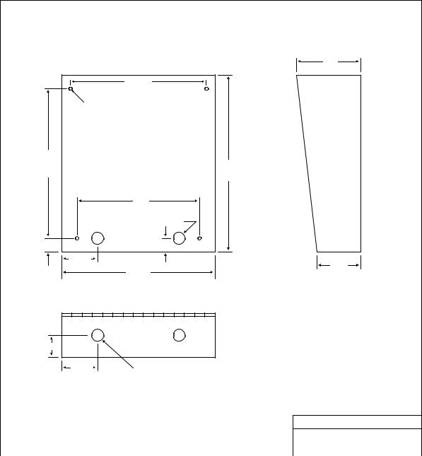
1.2Dimensions
Surface Mount 1810 Access Plus
Standard Surface Mount Housing Case and Mounting
Hole Dimensions
|
4.75 |
|
10.125 |
|
.25 DIA |
10.875 |
13.0 |
|
9.0 |
|
.875 DIA |
1 |
8.75 |
|
2.625 |
|
3.25 |
|
11.25 |
1.625
2.625 |
|
.875 DIA |
|
DOORKING, INC., INGLEWOOD, CA 90301
Title: Surface Mount Case and Mounting Hole
Dimensions
|
Date: 10/09 |
Dwg. No. M1810-AP-1 |
Rev. A |
Page 10 |
1810-162-J-1-12 |
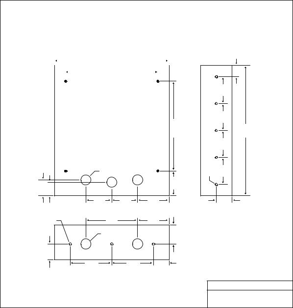
Surface Mount 1810 Access Plus with Recess Box/Trim Ring
Standard Surface Mount Recess Mounting Box (P/N 1803-150) |
|
|
|
|
|
|
|||
|
13.375 |
|
|
3.625 |
|
|
|
|
|
1.625 |
|
|
|
|
|
|
|
||
|
|
|
|
|
|
|
|
|
|
2.187 |
10.125 |
|
|
.437 |
|
|
|
|
|
|
3.375 |
|
|
2.25 |
|
|
|
||
|
|
|
|
|
|
|
|||
|
10-24 x 1.25 STUD (4 PL) |
|
|
|
4.875 |
|
|
|
|
|
9.0 |
|
|
.25 DIA |
|
|
|
|
|
|
|
|
|
|
|
|
|
||
|
|
|
|
|
|
|
8.375 |
|
|
10.875 |
|
|
|
|
|
|
11.0 |
|
|
|
|
8.5 |
15.25 |
|
|
13.25 |
|
|
|
|
9.0 |
|
|
|
|
|
|
|
|
|
.25 DIA |
|
|
|
|
|
|
|
|
|
1.375 DIA |
|
|
|
|
|
|
|
|
2.187 |
|
|
|
|
|
|
|
|
|
|
6.0 |
|
3.687 |
|
|
|
|
|
|
1.125 |
6.0 |
|
|
|
|
|
|
|
|
2.687 |
|
|
|
|
|
|
|
|
|
2.063 |
.25 DIA |
|
|
|
Surface Mount Entry System |
|
|
Recess Mount Box |
|
3.5 |
3.5 |
2.187 |
|
|
|
|
|||
.437 |
11.375 |
|
|
|
|
|
|
|
|
|
|
|
|
|
|
|
|
|
|
|
|
|
|
|
DOORKING, INC., INGLEWOOD, CA 90301 |
|
|||
|
|
|
|
Title: Surface Mount Recess Mounting Box |
|
|
|||
|
|
|
|
Date: |
11/09 |
Dwg. No. |
M1800-065-2 |
Rev. |
C |
1810-162-J-1-12 |
Page 11 |

Flush Mount 1810 Access Plus
Flush Mount Units
1.125 |
12.0 |
1.125 |
|
|
|
|
|
||
|
10.125 |
|
|
|
|
.25 DIA |
|
|
|
|
|
|
10.875 |
13.25 |
.875 |
|
9.0 |
|
|
.875 DIA |
.50 |
|
|
|
|
|
|
|
|
2.625 |
|
|
2.625 |
|
|
5.625 |
|
|
|
|
11.25 |
|
|
|
1.625 |
.875 DIA |
|
|
|
2.5 |
3.0
13.0
DOORKING, INC., INGLEWOOD, CA 90301
Title: Flush Mount Units
Date: 10/05 Dwg. No. M1800-065-3 Rev. B
Page 12 |
1810-162-J-1-12 |
Flush Mount Rough-in Box (1810 Access Plus only)
Flush Mount Rough-in Box
(Flush mount rough-in box is included with the 1814-165 and 1814-166 flush mount kits)
|
|
12.800 |
|
|
|
|
|
|
||
|
|
|
|
|
|
|
||||
|
|
|
|
|
|
|
|
|
|
|
|
|
|
|
|
|
|
|
|
|
1.914 |
|
|
|
|
10.120 |
|
|
|
|
|
|
|
|
|
|
|
|
|
||||
|
|
|
|
|
|
|
|
|
|
|
 10-32 x .75 Stud (4 PL)
10.886
|
1.125 DIA (3 PL) |
|
|
1.685 |
1.500 |
|
1.800 |
|
3.000 |
3.000 |
3.400 |
.275 DIA (3 PL) |
6.000 |
3.400 |
|
|
1.125 DIA (2 PL) |
1.800 |
|
|
|
||
|
1.740 |
|
|
|
4.700 |
4.700 |
1.700 |
1.300

 3.450
3.450 

|
3.000 |
|
3.000 |
|
14.600 |
PL) |
3.000 |
.275 DIA (5 |
3.000 |
|
1.740 |
DOORKING, INC., INGLEWOOD, CA 90301
Title: Flush Mount Rough-in Box
Date: 4/11 |
Dwg. No. M1800-065-4 |
Rev. D |
1810-162-J-1-12 |
Page 13 |

Flush Mount Trim Ring (1810 Access Plus only)
Flush Mount Trim Ring (P/N 1814-165 and 1814-166) |
|
|
|
|
|
|
14.700 |
|
|
|
|
|
|
|
|
3.450 |
|
|
10.120 |
|
|
|
|
.286 DIA (4 PL) |
|
|
|
|
|
1.250 |
|
|
|
|
|
|
|
10.886 |
16.055 |
|
13.555 |
|
1.250 DIA (3 PL) |
|
|
|
|
3.000 |
3.000 |
|
|
|
|
1.250 DIA (3 PL) |
1.325 |
|
|
|
|
|
|
|
|
|
|
3.100 |
4.505 |
1.575 |
Rough-in Box |
Trim Ring |
EntrySystem |
3.100 |
|
|
|
||
|
12.200 |
|
|
|
|
DOORKING, INC., INGLEWOOD, CA 90301
Title: Flush Mount Trim Ring
|
Date: 4/11 |
Dwg. No. M1800-065-5 |
Rev. D |
Page 14 |
1810-162-J-1-12 |

Surface Mount Trim Ring for Flush Mount Units (1810 Access Plus only)
Surface Mounting Kit for Flush Style Units (P/N 1814-152)
|
12.0 |
|
|
|
|
1.0 |
|
|
|
|
|
.375 |
|
|
|
|
|
|
9.0 |
|
|
|
|
|
7.5 |
|
.375 |
.875 |
1.125 |
|
6.0 |
3.0 |
|||
|
|
|
|
|
|
1.125 DIA |
1.125 SQ |
|
|
|
|

 2.625
2.625 

13.5
Flush Mount Ring |
|
|
Flush Unit |
|
|
|
|
|
|
|
|
DOORKING, INC., INGLEWOOD, CA 90301
Title: Surface Mount Kit for Flush Style Units
Date: 11/09 |
Dwg. No. M1800-065-6 |
Rev. B |
|
|
|
1810-162-J-1-12 |
Page 15 |
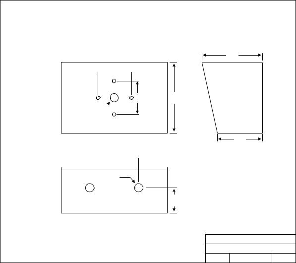
Surface Mount 1808 Access Plus
1808 Surface Mount Housing
6.375
 3.50
3.50 
3.50 |
7.375 |
.875
3.375
 3.0
3.0 

.875
2.625
DOORKING, INC., INGLEWOOD, CA 90301
Title: 1808 Surface Mount Case
Date: 9/03 Dwg. No. M1800-065-10 Rev. A
Page 16 |
1810-162-J-1-12 |
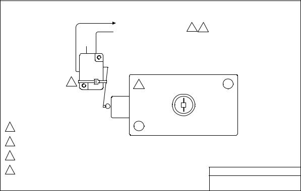
Postal Switch Installation (1810 Access Plus only)
The 1808 Access Plus unit does not have provisions for the installation of the postal switch. If letter carrier access is required when using the 1808, the postal switch can be mounted in the DoorKing P/N 1402-080 - Postal Lock Box.
Postal Lock Installation Detail
Common to Terminal 9
1 2
 Normally Closed to Terminal 7 or 8
3 |
4 |
|
Connect to terminal 7 to activate relay 1; connect to
1terminal 8 to activate relay 2.
Micro-switch is pre-wired. Controller terminals are shown
2for clarification only.
Cut tie-wrap only if postal lock is installed. Micro-switch is wired Normally Closed.
3Switch is held “open” by tie-wrap or postal lock when installed.
4Postal lock supplied by others.
DOORKING, INC., INGLEWOOD, CA 90301
Title: |
Postal Lock Installation Detail |
|
||
|
|
|
|
|
Date: |
10/09 |
Dwg. No. |
M1810-AP-2 |
Rev. A |
1810-162-J-1-12 |
Page 17 |
Page 18 |
1810-162-J-1-12 |

1.3Power Wiring
Do not run telephone lines / data lines and high voltage lines in the same conduit. Separate high voltage and telephone / data line conduits by at least six (6) inches.
|
POWER WIRING |
|
|
|
|
WIRE SIZE |
|
MAX DISTANCE IN FEET |
|
|
|
18 AWG |
|
100 |
|
|
|
16 AWG |
|
200 |
|
|
|
Access Plus Units operate on 16.5 VAC. Do not power these devices with 24 volt AC power. If the OV LED is ON, the input voltage is too high. Check the transformer to be sure it is rated at 16 VAC. Use the supplied power transformer, 16 VAC, 20 VA (or U.L. listed equivalent) to power the Access Plus unit. Do not power any other devices (electric strikes, magnetic locks, etc.) from this power transformer. For wire runs up to 100 feet, use 18 AWG wire. For wire runs up to 200 feet, use 16 AWG wire.
Surge Suppression and Grounding
Proper grounding and the use of surge suppressers can significantly reduce the chance of component failure because of static charges or surges. To be effective, ground connections should be made with a minimum 12 AWG wire to a ground point within 10 feet of the device being protected. The ground point must be at an electrical panel, a metallic cold water pipe that runs in the earth, or a grounding rod driven at least 10 feet into the soil. A gooseneck mounting post anchored in concrete does not make a good ground.
It is highly recommended that telephone line surge suppresser (DoorKing p/n 1877-010) be installed to help protect the system from phone line power surges and a low voltage surge suppresser (DoorKing p/n 1878-010) be installed to help protect the telephone entry system from power surges.
Surge suppresser must be provided a ground point within three (3) feet of the surge device.
|
1 |
1 |
|
|
|
|
|
|
|
|
|
|
|
|
|
2 |
TERMINATION |
|
|
|
|
|
|
|
|
|
|
||
|
3 |
2OFF |
ON |
RS-485 RX |
|
|
|
|
|
|
|
|
|
|
|
3 |
SW2 |
|
|
|
|
|
|
|
|
|
|
|
|
|
4 |
BAD DNS |
LAN DOWN |
|
|
|
|
|
|
|
|
|
||
|
5 |
4 |
|
LAN Connection |
|
ON |
|
|
|
|
|
|
|
|
|
6 |
5 |
|
SW1 |
MODEM / TCP ENB |
|
|
|||||||
|
|
Data Transmit |
|
Phone Line |
|
|
|
|||||||
|
7 |
6 |
|
|
|
|
|
|||||||
|
|
|
|
|
In Use |
|
|
|
||||||
|
8 |
|
|
|
|
|
|
|
|
|
|
|
||
|
7 |
|
|
|
|
|
|
|
|
|
|
|
|
|
|
9 |
|
|
|
|
|
|
|
|
|
|
|
|
|
|
8 |
|
|
|
|
|
|
|
|
|
|
|
|
|
|
10 |
|
|
|
|
|
|
|
|
|
|
|
|
|
|
|
|
|
|
|
|
|
|
|
|
|
|
|
|
|
11 |
|
|
|
|
|
|
|
|
|
|
|
|
Mic |
|
12 |
|
|
|
|
|
|
|
|
|
|
|
|
Vol |
|
|
|
|
|
|
|
|
|
|
|
|
|
|
|
|
13 |
|
|
|
Keypad |
|
|
|
|
|
|
|
|
|
|
14 |
|
|
|
|
|
|
|
|
|
|
|
|
|
|
15 |
|
|
|
|
|
|
|
|
|
|
|
|
|
|
16 |
|
|
|
|
|
|
|
|
|
|
|
|
|
Over Voltage |
17 |
|
|
|
|
|
|
|
|
|
|
|
|
|
18 |
|
|
|
|
|
|
|
|
|
|
|
|
|
|
LED |
|
|
|
|
|
|
|
|
|
|
|
|
|
|
|
|
|
|
|
|
|
|
|
|
|
|
|
Speaker |
|
|
|
|
|
|
|
|
|
|
|
|
|
|
|
|
|
OV |
|
|
|
|
|
|
|
|
|
|
|
|
Vol |
|
|
|
|
|
1 |
2 |
3 |
4 |
5 |
6 |
7 |
8 |
9 1011 |
|
1810-162-J-1-12 |
|
|
|
|
|
|
|
|
|
|
|
|
|
Page 19 |

1.4Telephone Auto-Dialer Wiring – Single Unit
From Phone |
White/Blue |
|
|
|
|
|
A |
|
|
|
|
|
|
|
|
|
|
|
|
|
|
|
|
|
|
|
|
|
|
1 |
|
|
|
|
|
|
|
|
|
|
|
|
|
|
|
||
Company |
Blue/White |
|
|
|
|
|
|
2 |
1 |
|
|
|
|
|
|
|
|
|
|
|
|
Master |
|
|
|
|
|
|
|
|
|
2 |
TERMINATION |
|
|
|
|
|
|
|
|
|
|
||||
|
|
|
|
|
|
|
|
|
|
|
|
|
|
|
|
|
|
|
|
Code |
|||
|
|
Tip |
Ring |
Gnd |
Gnd |
Tip |
Ring |
3 |
|
2OFF |
ON |
|
RS-485 RX |
|
|
|
|
|
|
|
|
|
|
|
White/Orange |
|
3 |
SW2 |
|
|
|
|
|
|
|
|
|
|
|
|
|||||||
|
|
|
|
|
|
|
4 |
|
|
|
|
|
|
|
|
|
|
|
|
|
|
||
|
|
|
|
|
|
|
|
|
|
BAD DNS |
|
LAN DOWN |
|
|
|
|
|
|
|
|
|
||
|
Orange/White |
Blue/White |
|
|
|
|
White/Blue |
5 |
|
4 |
|
LAN Connection |
Data Transmit |
SW1 |
ON |
|
|
In Use |
|
|
|
||
|
|
|
|
|
|
7 |
|
6 |
|
|
|
|
|
|
|
||||||||
|
|
White/Blue |
|
|
|
|
Blue/White |
6 |
|
5 |
|
|
|
|
Phone Line |
|
|
|
|||||
|
|
|
|
|
|
|
|
|
|
|
|
|
|
|
|
|
|
||||||
Vehicular Gate |
|
|
|
|
|
|
8 |
|
7 |
|
|
|
|
|
|
|
|
|
|
|
|
|
|
Operator |
|
|
|
|
|
|
|
|
|
|
|
|
|
|
|
|
|
|
|
|
|
||
|
|
|
|
|
|
6 |
9 |
|
|
|
|
|
|
|
|
|
|
|
|
|
|
||
|
|
|
|
|
|
|
|
8 |
|
|
|
|
|
|
|
|
|
|
|
|
|
||
|
1 |
6 |
|
|
1 |
|
10 |
|
|
|
|
|
|
|
|
|
|
|
|
|
|
||
|
|
|
|
|
|
|
|
|
|
|
|
|
|
|
|
|
|
|
|||||
|
|
|
|
|
|
|
|
11 |
|
|
|
|
|
|
|
|
|
|
|
|
|
|
Mic |
|
|
|
|
|
|
|
|
12 |
|
|
|
|
|
|
|
|
|
|
|
|
|
|
Vol |
|
|
|
|
|
|
|
|
|
|
|
|
|
|
|
|
|
|
|
|
|
|
|
|
|
|
|
|
|
|
|
|
13 |
|
|
|
|
|
Keypad |
|
|
|
|
|
|
|
|
|
|
|
|
|
|
|
|
|
14 |
|
|
|
|
|
|
|
|
|
|
|
|
|
|
|
|
|
|
|
|
|
|
|
15 |
|
|
|
|
|
|
|
|
|
|
|
|
|
|
|
|
|
|
|
|
16.5 VAC |
16 |
|
|
|
|
|
|
|
|
|
|
|
|
|
|
|
||
|
|
|
|
|
17 |
|
|
|
|
|
|
|
|
|
|
|
|
|
|
|
|||
|
Mag Lock |
|
|
3 |
|
20 VA |
5 |
|
|
|
|
|
|
|
|
|
|
|
|
|
|
|
|
|
|
|
|
|
18 |
|
|
|
|
|
|
|
|
|
|
|
|
|
|
|
|||
|
Power |
4 |
B |
|
|
|
|
|
|
|
|
|
|
|
|
|
|
|
|
|
|
||
|
|
|
|
|
|
|
|
|
|
|
|
|
|
|
|
|
|
|
|
Speaker |
|||
|
|
|
|
|
|
|
|
|
|
|
|
|
|
|
|
|
|
|
|
|
Vol |
||
Pedestrian |
|
|
|
|
|
|
|
|
|
|
|
|
|
|
1 |
2 |
3 |
4 |
5 |
6 |
7 |
8 |
9 1011 |
|
|
|
|
|
|
|
|
|
|
|
|
|
|
|
|
|
|
|
|
|
|
|
|
Gate / Door |
|
|
|
|
|
|
|
|
|
|
|
|
|
|
|
|
|
|
|
|
|
|
|
1
2
3
4
5
6
Use only twisted pair telephone wire that is rated for direct underground burial.
DO NOT use wire that is intended for indoor applications . Recommend Cat5e Gel Filled (flooded) UV Resistant Direct Burial Cable in conduit. DO NOT run telephone wires and high voltage wires in the same conduit .
Check the phone wire chart for wire size / distance.
Check for polarity on the phone "IN" wires, terminals 1 and 2. Terminal 2 must be positive with respect to terminal 1. Set a VOM meter to measure DC volts. Place the positive lead on terminal 2 and the negative lead on terminal 1. If the meter shows a positive voltage - OK. If the meter shows a negative voltage (needle moves off scale to the left), reverse the wires on terminals 1 and 2.
Use supplied 16.5 VAC, 20 VA power transformer or UL Listed equivalent. DO NOT Power this device with a 24 Volt transformer or source voltage.
Magnetic locks or electric strikes must be powered from a separate UL Listed power transformer. Do not power strikes or magnetic locks from the 1810 power transformer.
Use minimum 18 AWG wire for runs up to 100 feet; 16 AWG wire for runs up to 200 feet. It is recommended to keep power wire runs as short as possible. Check the power wire chart for wire size / distance.
Be sure to properly ground all devices. Minimum 12 AWG wire. Surge devices must have a ground point within 3-ft of the device.
A Optional DoorKing Surge Suppresser P/N 1877-010 (or equivalent) highly recommended.
For best protection, surge suppresser ground wire must be 3-ft. or less in length. Use minimum 12 AWG wire.
Ring is Positive with respect to Tip terminal. See
B This device is powered by a 16.5 VAC transformer. DO NOT power this device with a 24 VAC transformer or power source.
DOORKING, INC., INGLEWOOD, CA 90301
Title: Access Plus System Auto-Dialer Wiring
Basic wire connections – single unit.
Date: 1/12 Dwg. No. M1810-AP-6-C Rev. C
Page 20 |
1810-162-J-1-12 |
Loading...