


|
Installation/Owner’s Manual |
Model 1812 Classic |
|
|
Residential Telephone Intercom/Access Control System |
||
|
|
|
|
|
Use this manual for circuit board 1871-010 Revision S or higher. |
1812-065-U-12-13 |
|
|
|
Control a main door and gate. |
|
1 |
2 |
|
|
|
|
|
4 |
|
|
|
|
|
|
3 |
|
|
|
|
|
|
|
5 |
P |
|
|
|
|
7 |
6 |
|
|
|
|
|
|
|
u |
|
|
|
|
|
8 |
s |
|
|
|
|
|
h |
|
|
|
|
|
|
9 |
|
B |
|
|
|
|
T |
u |
|
|
||
|
|
|
t |
|
||
|
0 |
o |
|
t |
|
|
|
|
C |
|
o |
||
|
|
|
|
|
n |
|
|
|
|
all |
|
||
Surface |
Mount |
|
1
 2
2 4
4
 5
5 7
7

 8
8

 0
0
Wall |
Mount |
|
3 6 9
Date Installed:
Installer/Company Name:
Phone Number:
Leave Manual with Owner
1 |
2 |
|
|
|
|
|
4 |
|
|
|
|
|
|
3 |
|
|
|
|
|
|
|
5 |
P |
|
|
|
|
7 |
6 |
|
|
|
|
|
|
|
u |
|
|
|
|
|
8 |
s |
|
|
|
|
|
h |
|
|
|
|
|
|
9 |
|
B |
|
|
|
|
T |
u |
|
|
||
|
|
|
t |
|
||
|
0 |
o |
|
t |
|
|
|
|
C |
|
o |
||
|
|
|
|
|
n |
|
|
|
|
all |
|
||
Flush |
Mount |
|
Circuit Board
Serial Number
and Revision Letter:
Copyright 2013 DoorKing, Inc. All rights reserved.
Copyright 2009 DoorKing, Inc. All rights reserved.

SPECIFICATIONS
For Model 1812 Classic with circuit board 1871-010 Rev S or higher ONLY.
1 |
2 |
3 |
4 |
5 |
6 |
7 |
8 |
9 |
10 |
11 |
12 |
13 |
14 |
15 |
16 |
17 |
18 |
Features
•Unique telephone communication system allows homeowners to use their telephone as an intercom to speak to a guest at a front door or gate, and to control access to their property.
•Unit connects directly to the homeowners existing telephone line. No additional monthly expense for a second telephone line.
•Built in call waiting assures that incoming calls or guest calls are not missed.
•Two internal relays allow the system to control a main entry gate plus a pedestrian access gate.
•Built-in clock / calendar provides the following time related functions:
1.Do-not-disturb time zone.
2.Four hold-open time zones.
3.Access code time zone.
4.Call forward time zone.
5.Flash access code.
•Unit can be programmed to work with PBX and KSU phone systems.
•Optional secondary keypad can be added for remote access code activation of door or gate.
1
 2 4
2 4
 5 7
5 7

 8
8

 0
0
 3
3
6 |
Pu |
|
|
|
9 |
sh |
Bu |
|
|
|
To |
C |
tt |
|
|
|
|
on |
|
|
|
all |
||
1 |
2 |
|
4 |
||
3 |
||
|
5 |
|
7 |
6 |
|
|
8 |
|
|
9 |
|
|
0 |
1 |
2 |
|
|
|
|
4 |
|
|
|
|
|
3 |
|
|
|
|
|
|
5 |
P |
|
|
|
7 |
6 |
|
|
|
|
|
8 |
us |
|
|
|
|
h |
Bu |
|
||
|
9 |
|
|
||
|
0 |
To |
C |
tt |
|
|
|
|
on |
||
|
|
|
all |
||
Surface Mount |
Wall Mount |
Flush |
|
|
Mount |
DoorKing, Inc. reserves the right to make changes in the products described in this manual without notice and without obligation of DoorKing, Inc. to notify any persons of any such revisions or changes. Additionally, DoorKing, Inc. makes no representations or warranties with respect to this manual. This manual is copyrighted, all rights reserved. No portion of this manual may be copied, reproduced, translated, or reduced to any electronic medium without prior written consent from DoorKing, Inc.
1812-065-U-12-13 |
1 |
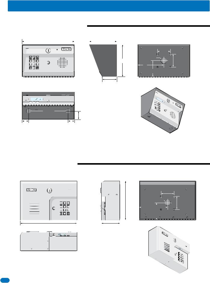
SPECIFICATIONS
Surface Mount Dimensions
|
|
Front View |
Side View |
Back View |
|||||||
|
|
|
|
|
|
|
|
|
|
|
|
|
|
|
10” |
|
|
|
5.25” |
|
|
|
|
|
|
|
|
|
|
|
|
|
|
|
|
|
|
|
|
|
|
|
|
|
|
|
|
|
|
|
|
|
2.5” |
1 |
2 |
3 |
Push Button |
6.125” |
1.125” Dia |
4 |
5 |
6 |
To Call |
2.5” |
7 |
8 |
9 |
5” |
|
0 |
|
|
|
|
|
3”
2.875”
875” Dia
1.75”
1.125” |
1.125” |
Bottom View
1 2 4 5 7 
 8
8
 0
0
 3
3  6
6  9
9
P |
|
|
|
|
us |
|
|
|
|
h |
|
|
|
|
Bu |
|
|
||
To |
|
tt |
||
|
C |
|
o |
|
|
|
|
n |
|
|
all |
|
||
Wall Mount Dimensions
Front View |
|
|
|
|
|
Side View |
|
|
|
Back View |
||||||
|
|
|
|
|
|
|
|
|
|
|
|
|
|
|
|
|
|
|
|
|
|
|
|
|
|
|
|
|
|
|
|
|
|
|
|
|
|
|
|
|
|
|
|
|
|
|
|
|
|
|
|
|
|
|
|
|
|
|
|
|
|
|
|
|
|
|
|
|
|
|
|
|
|
|
|
|
|
|
|
|
|
|
|
2.5” |
|
|
|
|
|
|
|
|
|
|
|
|
|
|
|
|
|
|
|
|
|
|
|
|
|
|
|
|
|
|
|
|
|
|
|
|
|
|
|
|
|
|
|
|
|
|
|
|
|
|
1.125” Dia |
|
|
|
|
|
|
|
|
|
|
|
|
|
|
|
|
|
|
|
|
|
|
|
|
|
|
|
|
|
|
7.325” |
|
|
|
|
|
1 |
|
2 |
|
3 |
|
|
|
|
|
|
|
|
|
2.5” |
|
|
|
|
|
|
|
|
|
|
|
|
|
|
|
|
|
4 |
5 |
6 |
5.375” |
|
7 |
8 |
9 |
||
|
|
|
|
|
|
|
|
|
|
|
|
|
|
|
|
|
|
|
|
3.375” |
|
|
|
|
|
|
|
|
0 |
|
||||||||||
|
|
|
|
|
|
|
|
|
|
|
|
|
|
|
|
|
|
|
|
|
|
|
|
|
|
|
|
|
|
|
|
|
|
|
|||||
|
|
|
|
|
|
|
|
|
|
|
|
|
|
||||||
|
10.75” |
|
|
|
|
|
|
|
|
3.5” |
|
|
|
||||||
|
|
|
|
|
|
|
|
|
|
|
|
|
|
|
|
|
|
|
|
|
|
|
|
|
|
|
|
|
|
|
|
|
|
|
|
|
|
|
|
|
|
|
|
|
|
|
|
|
|
|
|
|
|
|
|
|
|
|
|
Bottom View
1 2 4 5 7 
 8
8
 0
0
 3
3  6
6  9
9
2 |
1812-065-U-12-13 |

SPECIFICATIONS
Flush Mount Dimensions
Side Views
Rough-In Box |
|
Flush Box |
|
|
|
|
|
25”.6 25”.7 |
7.5” |
||
|
|
|
|
|
|
|
|
|
|
|
|
|
|
|
|
|
|
|
|
|
|
|
|
|
|
|
|
|
|
|
|
|
|
|
|
|
|
|
|
|
4.25” |
|
|
4.5” |
|
|
|
|
|
|
||
|
|
|
|
|
|
|
|
|
|
|
|
|
|
|
|
|
|
|
|
|
|
|
Front Views |
|
|
|
|
|
Flush Box |
1 |
2 |
3 |
Push Button |
Bolt holes (4) to secure flush box |
4 |
5 |
6 |
To Call |
|
7 |
8 |
9 |
9.25” |
inside rough-in box. |
|
0 |
|
|
|
|
|
|
|
|
|
|
|
|
|
|
|
|
|
|
|
|
|
|
Flush Box |
|
|
Rough-In Box |
|
12”
10”
3.5”
Flush Box
.875” Dia |
|
5” |
2.5” |
Bottom Views
10.25”
3.5”
Rough-In Box
 1.25” Dia
5” 
 2.625”
|
|
|
Flush |
|
|
-In |
Box |
|
|
|
|
R |
ough |
|
|
|
x |
|
|
Bo |
|
||
|
|
||
1 2 4 5 7 
 8
8
 0
0
 3
3  6
6  9
9
P |
|
|
|
us |
|
|
|
hB |
|
|
|
T |
u |
|
|
o |
C |
tto |
|
|
|
n |
|
|
all |
|
|
1812-065-U-12-13 |
3 |

|
|
|
|
|
|
|
|
|
|
|
|
|
|
|
|
|
|
|
|
|
TABLE OF CONTENTS |
|
|
|
|
|||||||||||||||||
SPECIFICATIONS |
1 |
|||||||||||||||||||||||||||||||||||||||||
Features |
|
|
|
|
|
|
|
|
|
|
|
|
|
|
|
|
|
|
|
|
|
|
|
|
|
|
|
|
|
|
|
|
|
|
|
|
|
|
|
1 |
||
|
|
|
|
|
|
|
|
|
|
|
|
|
|
|
|
|
|
|
|
|
|
|
|
|
|
|
|
|
|
|
|
|
|
|
|
|
|
|
||||
Surface Mount Dimensions |
|
|
|
|
|
|
|
|
|
|
|
|
|
|
|
|
|
|
|
|
|
|
|
|
|
|
|
|
|
2 |
||||||||||||
|
|
|
|
|
|
|
|
|
|
|
|
|
|
|
|
|
|
|
|
|
|
|
|
|
|
|
|
|
||||||||||||||
Wall Mount Dimensions |
|
|
|
|
|
|
|
|
|
|
|
|
|
|
|
|
|
|
|
|
|
|
|
|
|
|
|
|
|
|
2 |
|||||||||||
|
|
|
|
|
|
|
|
|
|
|
|
|
|
|
|
|
|
|
|
|
|
|
|
|
|
|
|
|
|
|||||||||||||
Flush Mount Dimensions |
|
|
|
|
|
|
|
|
|
|
|
|
|
|
|
|
|
|
|
|
|
|
|
|
|
|
|
|
|
|
3 |
|||||||||||
|
|
|
|
|
|
|
|
|
|
|
|
|
|
|
|
|
|
|
|
|
|
|
|
|
|
|
|
|
|
|||||||||||||
Important Notices FCC - United States, DOC - Canada |
|
|
|
|
|
|
|
|
|
4 |
||||||||||||||||||||||||||||||||
|
|
|
|
|
|
|
|
|
||||||||||||||||||||||||||||||||||
General Information Installation Guidelines and Safety Information |
|
|
5 |
|||||||||||||||||||||||||||||||||||||||
|
|
|||||||||||||||||||||||||||||||||||||||||
SECTION 1 - INSTALLATION |
8 |
|||||||||||||||||||||||||||||||||||||||||
1.1 |
Mount the 1812 Classic |
|
|
8 |
||||||||||||||||||||||||||||||||||||||
|
Different Mounting Configurations of the 1812 Classic Models |
|
|
9-10 |
||||||||||||||||||||||||||||||||||||||
1.2 |
Install By-Pass Board for “Telephone Mode” Configurations |
|
|
11 |
||||||||||||||||||||||||||||||||||||||
1.3 |
Telephone Line Wire |
|
|
12 |
||||||||||||||||||||||||||||||||||||||
1.4 |
Power Wiring |
|
|
13 |
||||||||||||||||||||||||||||||||||||||
1.5 |
Grounding and Surge Suppression |
|
|
13 |
||||||||||||||||||||||||||||||||||||||
1.6 |
Wire One 1812 to a Telco Line - Telephone Mode |
|
|
14 |
||||||||||||||||||||||||||||||||||||||
1.7 |
Wire One 1812 to the Internet - Telephone Mode |
|
|
15 |
||||||||||||||||||||||||||||||||||||||
1.8 |
Wire Multiple 1812s: Telco/Internet - Telephone Mode |
|
|
16 |
||||||||||||||||||||||||||||||||||||||
1.9 |
Wire One 1812 - Intercom Mode |
|
|
17 |
||||||||||||||||||||||||||||||||||||||
1.10 |
Wire Multiple 1812s - Intercom Mode |
|
|
18 |
||||||||||||||||||||||||||||||||||||||
1.11 |
Main Terminal Description |
|
|
19 |
||||||||||||||||||||||||||||||||||||||
SECTION 2 - PROGRAMMING |
19 |
|||||||||||||||||||||||||||||||||||||||||
2.1 |
Programming Methods |
|
|
|
|
|
|
|
|
|
|
|
|
|
|
|
|
|
|
19 |
||||||||||||||||||||||
|
|
|
|
|
|
|
|
|
|
|
|
|
|
|
|
|
|
|||||||||||||||||||||||||
2.2 |
Master Code |
|
|
|
|
|
|
|
|
|
|
|
|
|
|
|
|
|
|
|
|
|
20 |
|||||||||||||||||||
|
|
|
|
|
|
|
|
|
|
|
|
|
|
|
|
|
|
|
|
|
||||||||||||||||||||||
2.3 |
System Parameters Programming |
|
|
|
|
|
|
|
|
|
|
|
|
|
21 |
|||||||||||||||||||||||||||
|
|
|
|
|
|
|
|
|
|
|
|
|
||||||||||||||||||||||||||||||
|
Programming from the System Keypad |
|
|
|
|
|
|
|
|
|
|
|
|
|
|
21 |
||||||||||||||||||||||||||
|
|
|
|
|
|
|
|
|
|
|
|
|
|
|
||||||||||||||||||||||||||||
|
Programming from a Touch-Tone Telephone |
|
|
|
|
|
|
|
|
|
|
|
21 |
|||||||||||||||||||||||||||||
|
|
|
|
|
|
|
|
|
|
|
|
|||||||||||||||||||||||||||||||
|
Quick Reference Table |
22 |
||||||||||||||||||||||||||||||||||||||||
|
2.3.1 Phone Mode or Intercom Mode |
|
|
|
|
|
|
|
|
|
|
|
|
23 |
||||||||||||||||||||||||||||
|
|
|
|
|
|
|
|
|
|
|
|
|
||||||||||||||||||||||||||||||
|
2.3.2 |
System Set-Up Code |
|
|
23 |
|||||||||||||||||||||||||||||||||||||
|
2.3.3 |
Talk Time |
|
|
|
|
|
|
|
|
|
|
|
|
|
|
23 |
|||||||||||||||||||||||||
|
|
|
|
|
|
|
|
|
|
|
|
|
|
|
||||||||||||||||||||||||||||
|
2.3.4 |
Relay Strike Time |
|
|
|
|
|
|
|
|
|
|
|
|
|
24 |
||||||||||||||||||||||||||
|
|
|
|
|
|
|
|
|
|
|
|
|
|
|||||||||||||||||||||||||||||
|
2.3.5 |
Tone Open Numbers |
|
|
|
|
|
|
|
|
|
|
|
|
24 |
|||||||||||||||||||||||||||
|
|
|
|
|
|
|
|
|
|
|
|
|
||||||||||||||||||||||||||||||
|
2.3.6 Answer Incoming Call on X Rings |
|
|
|
|
|
|
|
|
|
|
|
25 |
|||||||||||||||||||||||||||||
|
|
|
|
|
|
|
|
|
|
|
|
|||||||||||||||||||||||||||||||
|
2.3.7 Answer Incoming Call - Enable / Disable |
|
|
|
|
|
|
|
|
25 |
||||||||||||||||||||||||||||||||
2.4 Time Functions |
|
|
|
|
26 |
|||||||||||||||||||||||||||||||||||||
|
|
|
|
|||||||||||||||||||||||||||||||||||||||
|
2.4.1 Time and Date Calendar Chip Programming |
|
|
|
|
|
|
26 |
||||||||||||||||||||||||||||||||||
|
|
|
|
|
|
|
||||||||||||||||||||||||||||||||||||
|
2.4.2 Do Not Disturb Time Zone Programming |
|
|
|
|
26 |
||||||||||||||||||||||||||||||||||||
|
|
|
|
|
||||||||||||||||||||||||||||||||||||||
|
2.4.3 Automatic Relay Activation Time Zones Programming |
|
|
|
|
27 |
||||||||||||||||||||||||||||||||||||
|
|
|
|
|
||||||||||||||||||||||||||||||||||||||
|
2.4.4 Access Code Time Zone Programming |
|
|
|
|
|
|
27 |
||||||||||||||||||||||||||||||||||
|
|
|
|
|
|
|
||||||||||||||||||||||||||||||||||||
|
2.4.5 Call Forward Time Zone Programming |
|
|
|
|
|
|
28 |
||||||||||||||||||||||||||||||||||
|
|
|
|
|
|
|
||||||||||||||||||||||||||||||||||||
|
2.4.6 “Flash ” Access Code Time Zone Programming (One Day Only) |
|
|
28 |
||||||||||||||||||||||||||||||||||||||
4 |
1812-065-U-12-13 |

TABLE OF CONTENTS
2.5 Programming Dial-Out Functions |
|
29 |
||||
2.5.1 Call Forward Phone Number Programming |
|
29 |
||||
2.5.2 |
Call Forward - Enable / Disable |
|
|
29 |
||
|
|
|||||
2.5.3 |
Preprogrammed Phone Numbers “Dial a Phone Number” |
|
29 |
|||
|
||||||
2.6 |
Access Codes to Operate Access Control Devices |
|
|
|
|
30 |
|||||||||||||||||||||||||
|
|
|
|
||||||||||||||||||||||||||||
|
2.6.1 Access Code Programming |
|
|
|
|
30 |
|||||||||||||||||||||||||
|
|
|
|
|
|||||||||||||||||||||||||||
|
2.6.2 Delete an Access Code |
|
|
|
|
|
30 |
||||||||||||||||||||||||
|
|
|
|
|
|
||||||||||||||||||||||||||
|
2.6.3 Delete All Access Codes |
|
|
|
|
30 |
|||||||||||||||||||||||||
|
|
|
|
|
|||||||||||||||||||||||||||
SECTION 3 - ADJUSTMENTS |
31 |
||||||||||||||||||||||||||||||
Speaker Volume |
|
|
|
|
|
|
|
|
|
|
|
|
|
|
|
|
|
|
|
|
|
|
|
|
|
|
|
|
31 |
||
|
|
|
|
|
|
|
|
|
|
|
|
|
|
|
|
|
|
|
|
|
|
|
|
|
|
|
|
||||
Microphone Gain |
|
|
|
|
|
|
|
|
|
|
|
|
|
|
|
|
|
|
|
|
|
|
|
|
|
|
|
31 |
|||
|
|
|
|
|
|
|
|
|
|
|
|
|
|
|
|
|
|
|
|
|
|
|
|
|
|
|
|||||
Interface Board LED Status |
|
|
|
|
|
|
|
|
|
31 |
|||||||||||||||||||||
|
|
|
|
|
|
|
|
|
|||||||||||||||||||||||
System Keypad and Push To Call Button |
|
|
|
31 |
|||||||||||||||||||||||||||
|
|
|
|||||||||||||||||||||||||||||
SECTION 4 - OPERATING INSTRUCTIONS |
32 |
||||||||||||||||||||||||||||||
4.1 |
Calling the Homeowner’s Phone from the 1812 |
|
|
|
|
32 |
|||||||||||||||||||||||||
|
|
|
|
||||||||||||||||||||||||||||
4.2 |
Call Waiting |
|
|
|
|
|
|
|
|
|
|
|
|
|
|
|
|
|
|
|
|
|
|
|
|
32 |
|||||
|
|
|
|
|
|
|
|
|
|
|
|
|
|
|
|
|
|
|
|
|
|
|
|
||||||||
4.3 |
Preprogrammed Phone Numbers |
|
|
|
|
|
|
|
|
|
32 |
||||||||||||||||||||
|
|
|
|
|
|
|
|
|
|||||||||||||||||||||||
4.4 |
Access Codes |
|
|
|
|
|
|
|
|
|
|
|
|
|
|
|
|
|
|
|
|
|
|
33 |
|||||||
|
Homeowner’s Programming Instructions (From Home Phone or 1812) |
|
|
||||||||||||||||||||||||||||
4.5 |
Call Forward - Enable / Disable |
|
|
|
|
|
|
|
|
|
|
|
33 |
||||||||||||||||||
|
|
|
|
|
|
|
|
|
|
|
|||||||||||||||||||||
4.6 |
Call Forward Time Zone - Enable / Disable |
|
|
|
|
|
|
34 |
|||||||||||||||||||||||
|
|
|
|
|
|
||||||||||||||||||||||||||
4.7 |
Do Not Disturb - Enable / Disable |
|
|
|
|
|
|
|
34 |
||||||||||||||||||||||
|
|
|
|
|
|
|
|||||||||||||||||||||||||
4.8 |
Access Code Time Zone - Enable / Disable |
|
|
|
|
|
34 |
||||||||||||||||||||||||
|
|
|
|
|
|||||||||||||||||||||||||||
4.9 |
Auto Relay Activation Time Zones - Enable / Disable |
|
|
|
34 |
||||||||||||||||||||||||||
|
|
|
|||||||||||||||||||||||||||||
4.10 |
Answer Incoming Call - Enable / Disable Only from Phone |
|
|
34 |
|||||||||||||||||||||||||||
|
|
||||||||||||||||||||||||||||||
4.11 |
Relay Activation Check |
|
|
|
|
|
|
|
|
|
|
|
35 |
||||||||||||||||||
|
|
|
|
|
|
|
|
|
|
|
|||||||||||||||||||||
4.12 |
Remote Programming |
|
|
|
|
|
|
|
|
|
|
|
35 |
||||||||||||||||||
|
|
|
|
|
|
|
|
|
|
|
|||||||||||||||||||||
4.13 |
Remote Relay Activation |
|
|
|
|
|
|
|
|
|
|
35 |
|||||||||||||||||||
|
|
|
|
|
|
|
|
|
|
||||||||||||||||||||||
4.14 |
Switch Input Operation (Terminals 6, 7, 8 & 9) |
|
|
35 |
|||||||||||||||||||||||||||
|
|
||||||||||||||||||||||||||||||
SECTION 5 - MAINTENANCE |
36 |
||||||||||||||||||||||||||||||
5.1 |
Troubleshooting |
|
|
|
|
|
|
36 |
|||||||||||||||||||||||
|
|
|
|
|
|
||||||||||||||||||||||||||
5.2 |
1812 Classic Wiring Schematic |
|
|
|
36 |
||||||||||||||||||||||||||
|
|
|
|||||||||||||||||||||||||||||
5.3 |
Phone Line Polarity |
|
|
|
|
37 |
|||||||||||||||||||||||||
|
|
|
|
||||||||||||||||||||||||||||
5.4 |
Isolating Noise Problems |
|
|
|
38 |
||||||||||||||||||||||||||
|
|
|
|||||||||||||||||||||||||||||
5.5 |
Troubleshooting Table |
|
|
38-39 |
|||||||||||||||||||||||||||
|
|
||||||||||||||||||||||||||||||
5.6 |
Accessories |
|
|
|
40 |
||||||||||||||||||||||||||
|
|
|
|||||||||||||||||||||||||||||
5.7 |
Programmed Information Log Sheets |
|
41-42 |
||||||||||||||||||||||||||||
|
|||||||||||||||||||||||||||||||
|
Master Code, Tone Open Numbers. Do Not Disturb, Call Forward, Access Codes and Automatic Relay Activation time zones. |
|
|
||||||||||||||||||||||||||||
|
Preprogrammed Phone Numbers. Access Code Log Sheet (01-25 Location Codes for Relay 1, 26-50 Location Codes for Relay 2). |
|
|
||||||||||||||||||||||||||||
1812-065-U-12-13 |
5 |

Important Notices
FCC – United States
This equipment has been tested and found to comply with the limits for a class A digital device, pursuant to Part 15 of the FCC Rules and Regulations. These limits are designed to provide reasonable protection against harmful interference when the equipment is operated in a commercial environment. This equipment generates, uses, and can radiate radio frequency energy and, if not installed and used in accordance with the instruction manual, may cause harmful interference to radio communications. Operation of this equipment in a residential area is likely to cause harmful interference in which case the user will be required to correct the interference at his own expense.
FCC Registration Number: DUF6VT-12874-OT-T
DOC - Canada
The Canadian Department of Communications label identifies certified equipment. This certification means that the equipment meets certain telecommunications network protective, operational, and safety requirements. The Department does not guarantee the equipment will operate to the users satisfaction.
Before installing this equipment, users should ensure that it is permissible to be connected to the facilities of the local telecommunications company. The equipment must also be installed using an acceptable means of connection. The customer should be aware that compliance with the above conditions may not prevent degradation of service in some situations.
Repairs to certified equipment should be made by an authorized Canadian maintenance facility designated by the supplier. Any repairs or alterations made by the user to this equipment, or equipment malfunctions, may give the telecommunications company cause to request the user to disconnect the equipment.
Users should ensure, for their own protection, that the electrical ground connections of the power utility, telephone lines, and internal metallic water pipe system, if present, are connected together. This precaution may be particularly important in rural areas.
CAUTION: Users should not attempt to make such connections themselves, but should contact the appropriate electric inspection authority, or electrician, as appropriate.
DOC Registration Number: 1736 4507 A
Notice:
The Load Number (LN) assigned to each terminal device denotes the percentage of the total load to be connected to a telephone loop which is used by the device, to prevent overloading. The termination on a loop may consist of any combination of devices subject only to the requirement that the sum of the load numbers of all the devices does not exceed 100.
Notice:
DoorKing does not provide a power transformer on units sold into Canada. Use only transformers that are CSA listed to power the telephone entry system. The model 1812 Classic requires a 24-volt, 20 VA transformer.
Listing:
This product has been tested to and found to be in compliance with the U.L 294 Safety Standard by Intertek Testing Services NA Inc. (a Nationally Recognized Testing Laboratory) and is ETL listed.
6 |
1812-065-U-12-13 |

General Information
•Prior to beginning the installation of the telephone entry system, we suggest that you become familiar with the instructions, illustrations, and wiring guidelines in this manual. This will help insure that you installation is performed in an efficient and professional manner.
•The proper installation of the telephone entry panel is an extremely important and integral part of the overall access control system. Check all local building ordinances and building codes prior to installing this system. Be sure your installation is in compliance with local codes.
•When used to control a door or pedestrian gate, try to locate the telephone entry system as near as possible to the entry point. The unit should be mounted on a rigid wall to prevent excessive shock and vibration from closing doors or gates. Continuous vibration and shock from slamming doors or spring-loaded pedestrian gates will damage the circuit board.
Under no circumstances should the unit be mounted directly to a moving door or gate.
•ADA mounting requirements for door control. The requirements below apply only when the telephone entry system is being used to control entry through a public door only. If this system is used to control entry through a vehicular gate or private entrance, the dimensions noted below do not apply.
1.If the clear floor space allows only forward approach to the system, the maximum high forward reach allowed is
48 inches above grade to the top of the keypad.
2.If the high forward reach to the system is over an obstruction of greater than 20 inches but less than 25 inches, the maximum high forward reach allowed is 44 inches above grade to the top of the keypad.
3.If the clear floor space allows parallel approach by a person in a wheelchair, the maximum high side reach shall be 54 inches above grade to the top of the keypad.
4.If the high side reach is over an obstruction of 24 inches or less, the maximum high side reach allowed is 46 inches above grade to the top of the keypad.
•When used to control a vehicular gate with an automatic gate operator, the telephone entry system must be mounted a minimum of ten (10) feet away from the gate and gate operator, or in such a way that a person cannot operate the entry system and/or touch the gate or gate operator at the same time.
•Be sure that the system is installed so that it is not directly in the traffic lane. Goose neck mounting post and kiosks work well for these type systems. When planning where to locate the system, take into consideration traffic lane layouts, turn around lanes for rejected access, conduit runs, power availability, etc.
•Environmental factors must also be taken into account. Surface mount units are designed for direct outdoor installations, however it is preferable to protect them from direct exposure to driven rain or snow whenever possible. Flush mount units must be protected from direct exposure to the elements.
•This telephone entry system contains a number of static sensitive components that can be damaged or destroyed by static discharges during installation or use. Discharge any static prior to removing the circuit board from the lobby panel by touching a proper ground device.
•Instruct the end user to read and follow these instructions. Instruct the end user to never let children play with or operate any access control device. This Owner’s Manual is the property of the end user and must be left with them when installation is complete.
1812-065-U-12-13 |
7 |
SECTION 1 - INSTALLATION
Installation of the 1812 Classic Telephone Entry System involves the installation of the hardware, by-pass board, and the wiring of these components. Be sure that all dirt, metal or wood debris is removed from inside after mounting it. Any debris inside could damage the control board and cause the 1812 Classic system to malfunction during operation.
When the 1812 Classic is used to control a vehicular gate with an automatic gate operator, it must be mounted a minimum of ten (10) feet away from the gate and gate operator, or in such a way that a person
cannot operate the 1812 Classic system and/or touch the gate or gate operator at the same time.
WARNING
1.1 Mount the 1812 Classic
Use the specification dimensions on pages 2 and 3 to help with the installation of your chosen 1812 Classic model.
|
Remove the Control Board |
|
The control board removal is the same for all models. |
2 |
CAUTION The control board contains static sensitive |
1 |
|
3 |
components. Discharge any static electricity from |
4 |
|
5 |
your hands by touching a proper ground device |
7 |
|
6 |
|
8 |
before removing the control board. |
10 |
|
9 |
|
11 |
|
12 |
|
13 |
|
14 |
|
15 |
|
16 |
|
17 |
|
18 |
|
1. Unlock and open the 1812 door.
2. Disconnect the keypad plug and door accessories plug from the control board.
3. Remove the 4 screws.
Carefully remove control board.
Keep the control board in a protected area during the mounting installation.
8 |
|
1812-065-U-12-13 |
|
Different Mounting Configurations of the 1812 Classic Models
Surface and Wall mount models can be mounted directly to a wall, pilaster or post mounted using a DoorKing mounting post (there are several different styles available). The flush mount model is designed to be mounted into a pilaster, wall or kiosk. In any case, be sure it is securely mounted and is not subject to continuous vibration from closing doors or gates.
Mount on a Mounting Post
Use existing 4 holes in cabinet box to bolt the surface or wall mount models on a DoorKing mounting post. Use the hardware that is supplied with the mounting post.
Note: A gooseneck mounting post anchored in concrete does not make a good ground.
Mount Directly to a Wall or Pilaster
Use the 4 existing holes in the cabinet box. Run conduit inside or outside of wall or pilaster if desired. Use appropriate hardware to mount the cabinet (Not supplied). Be sure that the mounting hardware does not protrude into the cabinet where it could cause a short.
Plastic screw anchors for masonry if required. 
 (Not supplied)
Conduit |
|
|
(Shown |
inside |
|
|
wall) |
|
|
|
|
IMPORTANT Choose how your 1812 will function (Telephone Mode or Intercom Mode) on pages 14 thru 18 and run the indicated wires to the cabinet. Run ALL wires that will be needed during the cabinet installation.
1812-065-U-12-13 |
9 |

Flush Mount in a Pilaster, Wall or Kiosk
Mount rough-in box into the pilaster, wall or kiosk. Run conduit inside wall into bottom of rough-in box if desired. Use appropriate hardware (Not supplied) to secure the rough-in box in place.
7.5”
4 |
.5” |
|
Conduitin Wall 
Rough-In Box
10.25”
Bolt flush box into the rough-in box with 4 supplied bolts.
Flush
Box
4 |
|
7 |
5 |
8 |
6 |
0 |
9 |
IMPORTANT Choose how your 1812 will function (Telephone Mode or Intercom Mode) on pages 14 thru 18 and run the indicated wires to the rough-in box. Run ALL wires that will be needed during the mounting installation.
1

 2
2 
 3
3 
 4
4 
 5
5 
 6
6 
 7
7 
 8
8 

9 10 11 12 13
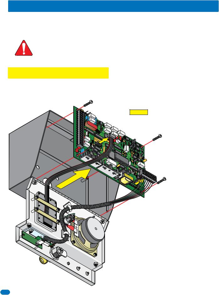
Re-install the Control Board
|
1 |
|
|
|
|
|
8- |
|
|
|
|
|
|
Pin |
|
|
|
|
Main |
|
CAUTION |
The control board contains static sensitive compo- |
|
|
Terminal |
|
nents. Discharge any static electricity from your hands by |
||
|
Connector |
|
|||
|
|
touching a proper ground device before re-installing the |
|||
|
|
|
|
||
|
|
|
|
control board. Also make sure that all dirt, metal or wood |
|
|
|
|
|
debris is removed from inside before re-installing the board. |
|
|
|
|
|
Remove the 18-pin main terminal connector from the control |
|
|
|
|
board by gently pulling it straight up. This will make wiring to the |
||
|
|
|
control board easier. Note the orientation and numbering sequence of the |
||
|
|
|
connector to correctly wire it. |
||
|
|
|
Re-install control board by carefully routing all incoming wires around it |
||
|
|
|
and secure it in place with 4 screws. Re-connect the keypad plug (cable |
||
Plug |
|
|
points down) and door accessories plug (red wire goes to the left) to the |
||
|
|
control board (See 5.2 on page 36 for 1812 wiring information). |
|||
|
|
|
|||
|
|
|
|
Connect all wires to the 18-pin connector (See page 19). |
|
|
Door |
|
|
Gently re-connect it back on the control board. DO NOT |
|
|
|
|
APPLY POWER to the 1812 at this time. |
||
|
Accessories |
|
|
||
|
Plug |
|
|
|
|
10 |
1812-065-U-12-13 |
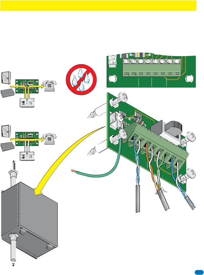
1.2 Install By-Pass Board for “Telephone Mode” Configurations
The 1812’s by-pass board provides a method to by-pass the 1812 and route the incoming telephone line directly to the homeowner’s phone. The By-Pass board IS NOT optional when using an incoming telephone line or internet (Telephone
Mode) – it must be installed as part of the 1812 system. All telephone wires for the 1812 must pass through the by-pass board. Wire the by-pass board either for a “Single 1812 - telephone mode” pages 14-15 or “Multiple 1812s - telephone mode”
page 16.
Mount the by-pass board in a location that is easily accessible by the homeowner. In case of 1812ENTRYtrouble orBYmaintenance,-PASS the
homeowner will use the by-pass switch on the board to route the incoming telephone line directly to their home phone. If the
SW1
by-pass board is installed outdoors, it must be installed in a NEMA Type 4 enclosure (not supplied) to protect the board from direct exposure to landscape sprinklers, rain, snow and other elements. 


“Entry” switch position:
Routes incoming phone line through 1812 and then to the home phone.
Incoming
Phone Line
|
|
|
|
|
|
ENTRY BY-PASS |
|
||||
|
|
|
|
|
|
|
|
|
|
SW1 |
|
OR |
|
|
|
|
|
|
|
1875-010 |
|
||
EARTH |
|
|
|
|
|
|
|
|
|||
|
|
VolP |
GND |
|
|
|
|
|
|
|
|
Fiber |
/ |
1 |
2 |
3 |
4 |
5 |
6 |
7 |
8 |
Home Phone |
|
|
OFFICE |
|
IN |
|
OUT |
HOME |
|||||
|
|
CENTRAL PHONE |
PHONE |
||||||||
Device |
|
|
|
|
|
|
|
|
|||
Internet
4 5 6 |
To Call |
7 |
8 |
9 |
|
0 |
|
EARTH
GND
RING |
TIP |
RING |
TIP |
TIP |
RING |
RING |
TIP |
|
|
|
|
|
|
|
|
|
|
|
|
|
|
|
|
1 |
2 |
|
3 |
4 |
5 |
6 |
7 |
8 |
|||||||
CENTRAL |
PHONE |
|
PHONE |
|
HOME |
||||||||||
OFFICE |
|
IN |
|
|
OUT |
|
|
|
|
||||||
“Tip” and “Ring” Configuration
“By-Pass” switch position: Routes incoming phone line directly to the home phone, bypassing 1812.
|
Incoming |
|
|
|
|
|
|
|
|
|
Phone Line |
|
|
|
|
|
|
||
|
|
|
|
|
ENTRY BY-PASS |
||||
|
|
|
|
|
|
|
|
|
SW1 |
|
|
|
|
|
|
|
|
|
1875-010 |
OR |
GND |
|
|
|
|
|
|
|
|
|
|
EARTH |
|
|
|
|
|
|
|
|
/VolP |
1 |
2 |
3 |
4 |
5 |
6 |
7 |
8 |
|
OFFICE |
|
IN |
|
OUT |
HOME |
|||
Fiber |
|
CENTRAL |
PHONE |
PHONE |
|||||
|
|
|
|
|
|
|
|
Home Phone |
|
Device |
|
|
|
|
|
|
|
||
Internet
4 5 6 |
To Call |
7 |
8 |
9 |
|
0 |
|
If installed outdoors.
|
NEMA |
|
|
|
|
enclosure |
|
||
|
|
|
Type |
|
|
|
|
|
4 |
|
outdoorfor |
|||
|
installation. |
|||
|
(Not |
Supplied) |
|
|
|
|
|
||
|
|
|
|
|
Four (4) mounting screws supplied.
EARTH GND
|
1 |
|
ENTRY |
||
|
|
2 |
3 |
|
|
|
|
|
4 |
||
|
|
|
|
||
|
|
|
|
|
|
1 |
3 |
|
|
|
|
CENTRAL |
|
|
|
|
|
2 |
|
|
|
|
|
OFFICE |
|
|
4 |
|
|
|
PHONE |
5 |
|
||
|
|
IN |
|
|
|
|
|
|
PHONE |
||
|
|
|
|
|
6 |
|
|
|
|
OU |
|
|
|
|
|
|
T |
BY- |
|
|
|
|
PASS |
|
|
5 |
SW1 |
|
|
6 |
7 |
|
|
|
8 |
||
|
|
||
|
|
|
|
|
|
1875- |
|
|
|
|
010 |
 7
7
HOME8
By-pass board MUST be |
|
|
|
properly grounded. |
From |
|
|
Minimum 12 AWG wire |
Incoming |
From |
|
(Not supplied). |
Telephone |
1812’s |
From |
|
Line |
18-Pin |
|
|
Home |
||
|
|
|
|
|
|
Terminal |
Phone |
|
|
|
Use only twisted pair telephone wire that is rated for direct underground burial. DO NOT use wire that is intended for indoor applications. Recommend Cat5e Gel Filled (flooded) UV Resistant Direct Burial Cable in conduit. DO NOT run telephone wires and high voltage wires in the same conduit. It is recommended to run all necessary wires to the by-pass board in a “dedicated” telephone wire conduit. Check the phone wire chart on next page for wire size and distances.
Dedicated
 Telephone
Wire Conduit
National Electrical Manufacturers’ Association (NEMA) - Type 4 - Enclosure constructed
 for outdoor use to provide a degree of protection to personnel against incidental contact with the enclosed equipment: to provide a degree of protection against falling dirt, rain, sleet,
snow, windblown dust, splashing water, and that will be undamaged by the external formation of ice on the enclosure.
1812-065-U-12-13 |
11 |
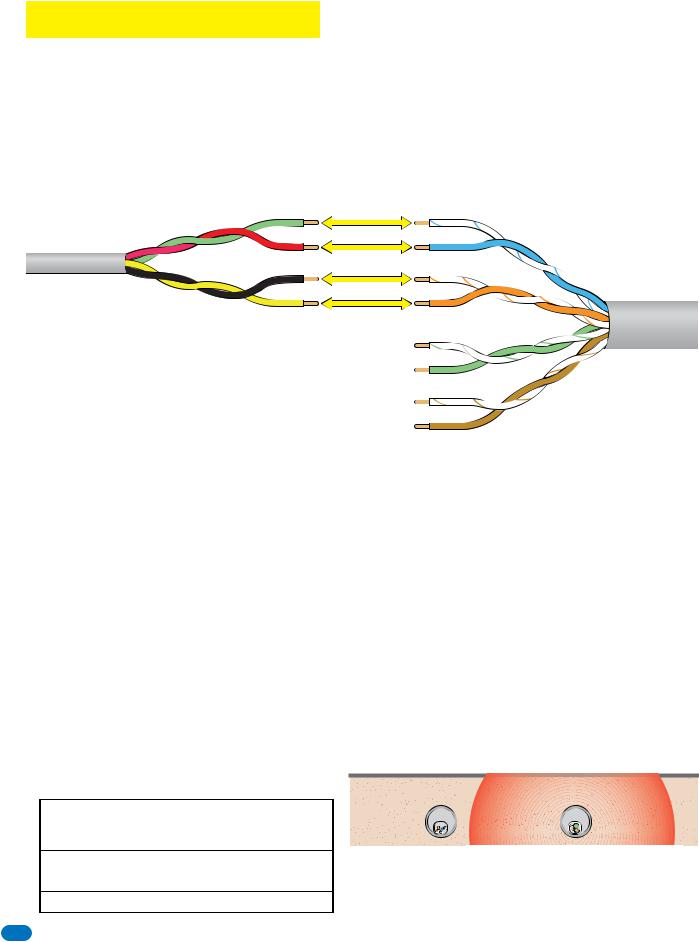
1.3 Telephone Line Wire
Be sure to observe electrical safety when working with phone lines. Phone lines carry electricity and the ring voltage can deliver a substantial jolt. The best policy is to disconnect the house phone from the phone company Network Interface Device (also known as ‘Demarcation Device’) before working on the wiring.
In most residential homes, the phone cable contains four wires; green, red, black, yellow. The green and red are twisted to make one pair and the black and yellow are twisted to make another pair (This allowed for the addition of a second phone line since telephones use only two wires). Most phone lines installed in the U.S. in the second half of the 20th Century have this type of wire. This type of wire is now obsolete. All new telephone projects are using Cat5 wire. If you have Cat5 wiring in your home, the conversion is simple:
|
Wire |
Green |
Conversion |
|
Four Conductor |
Red |
1st Line |
|
Wire |
|||
|
|
||
Older Residential |
Black |
|
|
Yellow |
2nd Line |
||
Homes |
|||
|
|
The convention for Cat5 wire is as follows:
• Colored pairs match; e.g., WHITE/blue mark (Tip +) wire goes
3rd Line
with BLUE/white mark (Ring -) wire for one phone line, etc.
•The pairs are used in the order pictured: for the first line, you use BLUE, for the second line you use ORANGE, etc.
4th Line
• An easy way to remember this is that the colors run from the sky to the earth. BLUE sky comes first; ORANGE sunset second; GREEN grass third; BROWN earth last.
Tip (+)
Ring (-)
(+) Tip Blue Pair
(-) Ring
Orange Pair
(+) Tip
(-) Ring
Green Pair
(+) Tip
(-) Ring
Brown Pair
Cat5 Wire
Modern Residential
Homes
“Tip” and “Ring” Definition. Common terms in the telephone service industry referring to the two wires or sides of an ordinary telephone line. Tip is the ground side (positive) and Ring is the battery (negative) side of a phone circuit. The ground side is common with the central office of the telephone company (telco); the battery side carries -48 volts of DC voltage when in an “Idle” or “On Hook” state.
Phone Line Polarity. Tip and ring reversal is mostly immaterial, except for special circuits including DID (Direct Inward Dialing) trunks, T-1 lines, and ground start lines where the field side (“terminal”) equipment (a company's PBX switch, for example) can only function correctly with correct tip and ring polarity.
Wire Type. It is extremely important to use the correct type of wire in telephone applications. Since the 1812 requires phone lines to be run outdoors or in an underground environment, we recommend that you use only wire that is rated for direct underground burial. For example, use Cat5e Gel Filled (flooded) UV Resistant Direct Burial Cable run in conduit for your 1812 phone line requirements. Do not use thinly insulated brown-jacketed telephone wire (the type found in the walls of a house) for outdoor or underground phone line wiring. Using improper wire can cause noise and hum on the phone line. Be sure that phone wire pairs are twisted.
Wire Size and Distance. Phone lines can be run up to 3600 feet, provided that the proper wire size is used.
Telephone Wire Run Table
Wire Size |
Max Distance |
24 AWG |
800 ft |
22 AWG |
1600 ft |
20 AWG |
2200 ft |
18 AWG |
3600 ft |
|
|
 Underground
 Cutaway


 Electrical field
 from power
 wires.


 Telephone


 18”
18” minimum


 High
High Voltage


 Wire
Wire Conduit


 Power
Power Wire
Wire


 Conduit


Note: Do not run telephone wires and high voltage power wires in the same conduit. Separate the high voltage conduit and the telephone conduit by at least 18 inches to prevent any electrical field interference that could occur.
12 |
1812-065-U-12-13 |
 Loading...