

Page 1

Owner’s Manual
1820
Telephone Intercom System with Call Down
DoorKing, Inc.
120 Glasgow Avenue
Inglewood, California 90301
U.S.A.
Phone: 310-645-0023
Fax: 310-641-1586
www.doorking.com
P/N 1820-065 REV E, 12/11
Copyright 2005 DoorKing, Inc. All rights reserved.
Page 2

Page 2 1820-065-E-12-11
Page 3

Use this manual with the following models only.
Model 1820 Telephone Intercom Systems with circuit board 1885-010, Rev A or higher.
DoorKing, Inc. reserves the right to make changes in the products described in this manual
without notice and without obligation of DoorKing, Inc. to notify any persons of any such revisions
or changes. Additionally, DoorKing, Inc. makes no representations or warranties with respect to
this manual. This manual is copyrighted, all rights reserved. No portion of this manual may be
copied, reproduced, translated, or reduced to any electronic medium without prior written consent
from DoorKing, Inc.
1820-065-E-12-11 Page 3
Page 4

Table of Contents
Preface
FCC (US) Notices.....................................................................................................................................................6
DOC (Canada) Notices.............................................................................................................................................7
General Information..................................................................................................................................................8
Section 1 – Installation
1.1 General Information ...............................................................................................................................9
1.1.1 Main and Auxiliary Cabinet Information....................................................................................10
1.1.2 Garden Style Cabinet Information............................................................................................11
1.2 RJ71C Phone Block Installation............................................................................................................12
1.3 Cabinet, Relay and Component Identification.....................................................................................14
1.3.1 Main Control Cabinet................................................................................................................14
1.3.2 Auxiliary Cabinets.....................................................................................................................14
1.3.3 Line Interface Boards...............................................................................................................16
1.3.4 Power Supply Boards...............................................................................................................16
Section 2 – Wiring
General Information..................................................................................................................................................19
2.1 Main Garden Style Cabinet ......................................................................................................................20
2.2 Main Cabinet ............................................................................................................................................21
2.2.1 Auxiliary Cabinets.....................................................................................................................22
2.3 Powered RJ71C Wiring............................................................................................................................23
2.3.1 Dual Line Interface Board Option.............................................................................................23
2.3.2 Dual RJ71C Option ..................................................................................................................23
2.4 Circuit Board Connector Locations...........................................................................................................26
2.5 Main Circuit Board Terminal Description..................................................................................................27
2.6 Entry System / Central Office Gain Adjustment........................................................................................28
Section 3 – Programming
3.1 System Set Up ........................................................................................................................................29
3.1.1 Master Code.............................................................................................................................29
3.1.2 1882 Relay Board / 1884 Interface Board Selection................................................................29
3.1.3 Last Available Relay.................................................................................................................30
3.1.4 Setting the System Time Clock................................................................................................31
3.1.5 Set the Caller ID Number.........................................................................................................31
3.1.6 Set the Talk Time.....................................................................................................................31
3.1.7 Number of Rings / Ring Type...................................................................................................32
3.1.8 Tone Open Number Programming...........................................................................................32
3.1.9 Relay Strike Time.....................................................................................................................32
3.2 Directory Codes......................................................................................................................................33
3.2.1 Programming Directory Codes.................................................................................................33
3.2.2 Turning Programmable Directory Codes On / Off....................................................................34
3.2.3 Directory Code for Doorman / Concierge Phone......................................................................34
3.2.4 Erasing All Programmed Directory Codes................................................................................34
3.3 Dedicated Phone Line Access ..............................................................................................................35
3.3.1 Doorman / Concierge Outside Line Access .............................................................................35
3.3.2 Preprogrammed Phone Numbers ............................................................................................35
3.3.3 Erase Preprogrammed Phone Number....................................................................................36
3.3.4 Erase All Preprogrammed Phone Numbers.............................................................................36
3.4 Entry Codes ............................................................................................................................................37
3.4.1 Programming Entry Codes.......................................................................................................37
3.4.2 Erasing Individual Entry Codes................................................................................................37
3.4.3 Erasing All Entry Codes ...........................................................................................................37
Page 4 1820-065-E-12-11
Page 5

3.5
3.6 Call Forwarding Features / Commands
3.7 Virtual Doorman
3.8 Call-Down Features / Commands
Do Not Disturb Feature / Commands
3.5.1 Do Not Disturb Feature On / Off System Wide ........................................................................38
3.5.2 Set 1-Time Do Not Disturb Timer for Residents.......................................................................38
3.5.3 Schedule Do Not Disturb On / Off............................................................................................39
3.5.4 Setting Do Not Disturb Schedule .............................................................................................39
3.6.1 Set Up Call Forwarding System Wide......................................................................................40
3.6.2 Call Forwarding On / Off per Resident.....................................................................................40
3.6.3 Program Call Forward Numbers ..............................................................................................41
3.6.4 Delete Call Forward Numbers..................................................................................................41
3.6.5 Program Call Forward Allowed Area Codes ............................................................................42
3.6.6 Delete Call Forward Allowed Area Codes................................................................................42
3.6.7 Delete All Call Forward Allowed Area Codes...........................................................................42
3.7.1 Virtual Doorman On / Off System Wide ...................................................................................43
3.7.2 Set Virtual Doorman Relay Strike Time ...................................................................................43
3.7.3 Virtual Doorman On / Off per Resident ....................................................................................43
3.8.1 Call-Down Feature On / Off System Wide ...............................................................................44
3.8.2 Set Doorman to Enable / Disable Direct Connect....................................................................44
3.8.3 Set Direct Connect Disable Timer............................................................................................45
3.8.4 Set Direct Connect Call-Down Number....................................................................................45
3.8.5 Set Resident Programming Number ........................................................................................45
Section 4 – Operating Instructions
4.1 Administrator and Doorman Commands
4.1.1 Lobby Panel On / Off................................................................................................................47
4.1.2 Calling the Lobby Panel ...........................................................................................................47
4.1.3 Accessing the Outside Phone Line..........................................................................................47
4.1.4 Calling a Preprogrammed Phone Number...............................................................................47
4.1.5 Calling the Doorman or Lobby Panel from an Off Site Location ..............................................48
4.1.6 Lobby Panel Relay Activation ..................................................................................................48
4.1.7 Calling a Resident without C.O. Phone Service From an Off Site Location.............................48
4.1.8 Turn Direct Connect On / Off ...................................................................................................49
4.1.9 Call Back a Resident................................................................................................................49
4.1.10 Clear Call Back Number Queue...............................................................................................49
4.2 Technician Commands
4.2.1 Reset Main Control Board........................................................................................................50
4.2.2 Reset Main Control Board Resident Programming..................................................................51
4.2.3 Set Touch-Tone Detect Time...................................................................................................52
4.2.4 Reset Line Interface Board Programming................................................................................52
4.2.5 Send Software Reset to all Line Interface Boards ...................................................................52
Appendix
Programming Table..................................................................................................................................................53
Resident Log Sheet..................................................................................................................................................54
RJ71C Phone Block Identification Sheet for Garden Style Main Cabinet ................................................................55
RJ71C Phone Block Identification Sheet for Garden Style Auxiliary Cabinet...........................................................56
RJ71C Phone Block Identification Sheet for Main Cabinet ......................................................................................57
RJ71C Phone Block Identification Sheet for Auxiliary Cabinet.................................................................................58
Resident Instruction Sheet........................................................................................................................................59
Resident Advanced Feature Programming Instructions...........................................................................................60
1820-065-E-12-11 Page 5
Page 6

FCC - UNITED STATES
This equipment complies with Part 68 of the FCC rules and the requirements adopted by the ACTA.
On the BOTTOM of this equipment is a label that contains, among other information, a product
identifier in the format US: AAAEQ##TXXXX. If requested, this number must be provided to the
telephone company.
This equipment uses the following Universal Service Order Codes (“USOC”) jacks: RJ11.
A plug and jack used to connect this equipment to the premises wiring and telephone network must
comply with the applicable FCC Part 68 rules and requirements adopted by the ACTA. A compliant
telephone cord and modular plug is provided with this product. It is designed to be connected to a
compatible modular jack that is also compliant. See installation instructions for details.
The REN is used to determine the number of devices that may be connected to a telephone line.
Excessive RENs on a telephone line may result in the devices not ringing in response to an incoming
call. In most but not all areas, the sum of RENs should not exceed five (5.0). To be certain of the
number of devices that may be connected to a line, as determined by the total RENs, contact the
local telephone company. For products approved after July 23, 2001, the REN for this product is part
of the product identifier that has the format US: AAAEQ##TXXXX. The digits represented by ## are
the REN without a decimal point (e.g., 03 is a REN of 0.3).
If this equipment Telecom Intercom System causes harm to the telephone network, the telephone
company will notify you in advance that temporary discontinuance of service may be required. But if
advance notice isn't practical, the telephone company will notify the customer as soon as possible.
Also, you will be advised of your right to file a complaint with the FCC if you believe it is necessary.
The telephone company may make changes in its facilities, equipment, operations or procedures that
could affect the operation of the equipment. If this happens, the telephone company will provide
advance notice in order for you to make necessary modifications to maintain uninterrupted service.
If trouble is experienced with this Telecom Intercom System, for repair or warranty information, please
contact DoorKing, Inc. at 310-645-0023. If the equipment is causing harm to the telephone network,
the telephone company may request that you disconnect the equipment until the problem is resolved.
There are no user serviceable parts in this equipment.
Connection to party line service is subject to state tariffs. Contact the state public utility commission,
public service commission or corporation commission for information.
If your home has specially wired alarm equipment connected to the telephone line, ensure the
installation of this Telecom Intercom System does not disable your alarm equipment. If you have
questions about what will disable alarm equipment, consult your telephone company or a qualified
installer.
Electrical Safety Advisory:
Parties responsible for equipment requiring AC power should consider including an advisory notice in
their customer information suggesting the customer use a surge arrestor.
FCC Registration Number: DUF6VT-12874-OT-T
Page 6 1820-065-E-12-11
Page 7

DOC – CANADA CUSTOMER INFORMATION
This product meets the applicable Industry Canada Technical Specifications. This is confirmed by the
registration number. The abbreviation, IC, before the registration number signifies that registration
was performed based on a Declaration of Conformity indicating that Industry Canada technical
specifications were met. It does not imply that Industry Canada approved the equipment.
The Ringer Equivalence Number (REN) for this terminal equipment is 0.1.
“The Ringer Equivalence Number is an indication of the maximum number of devices allowed to be
connected to a telephone interface. The termination on an interface may consist of any combination
of devices subject only to the requirement that the sum of the RENs of all devices does not exceed
five.”
DOC Registration Number: IC: 1736A-4530A
Notice:
DoorKing does not provide a power transformer on units sold into Canada. Use only transformers that
are CSA listed to power the telephone entry system. 1802, 1803, 1808, 1810, 1833, 1834, 1835,
1838 and all "P" series systems require a 16.5-volt, 20 VA transformer. The models 1816, 1820 and
1837 require a 16.5-volt, 50 VA transformer. The model 1812 requires a 24-volt, 20 VA transformer.
1820-065-E-12-11 Page 7
Page 8

General Information
Prior to beginning the installation of the telephone entry system, we suggest that you become
familiar with the instructions, illustrations, and wiring guidelines in this manual. This will help
insure that you installation is performed in an efficient and professional manner.
The proper installation of the telephone entry panel is an extremely important and integral
part of the overall access control system. Check all local building ordinances and building
codes prior to installing this system. Be sure your installation is in compliance with local
codes.
When used to control a door or pedestrian gate, try to locate the telephone entry system as
near as possible to the entry point. The unit should be mounted on a rigid wall to prevent
excessive shock and vibration from closing doors or gates. Continuous vibration and shock
from slamming doors or spring-loaded pedestrian gates will damage the circuit board. Under
no circumstances should the unit be mounted directly to a moving door or gate.
ADA mounting requirements for door control. The mounting of the unit shall be in such a
way that the LCD display is positioned so that it is readily visible to and usable by a person
sitting in a wheelchair with an approximate eye level of 45 inches and shall comply with the
following requirements:
1. If mounted vertically or tipped no more than 30 degrees away from the viewer, the
center line of the LCD
2. If the clear floor space allows only forward approach to the system, the maximum
high forward reach allowed is 48 inches above grade to the top of the keypad.
3. If the high forward reach to the system is over an obstruction of greater than 20
inches but less than 25 inches, the maximum high forward reach allowed is 44 inches
above grade to the top of the keypad.
4. If the clear floor space allows parallel approach by a person in a wheelchair, the
maximum high side reach shall be 54 inches above grade to the top of the keypad.
5. If the high side reach is over an obstruction of 24 inches or less, the maximum high
side reach allowed is 46 inches above grade to the top of the keypad.
When used to control a vehicular gate with an automatic gate operator, the telephone
entry system must be mounted a minimum of ten (10) feet away from the gate and gate
operator, or in such a way that a person cannot operate the entry system and/or touch
the gate or gate operator at the same time.
shall be located a maximum of 52 inches above grade.
Be sure that the system is installed so that it is not directly in the traffic lane. Goose neck
mounting post and kiosks work well for these type systems. When planning where to locate
the system, take into consideration traffic lane layouts, turn around lanes for rejected access,
conduit runs, power availability, etc.
Environmental factors must also be taken into account. Surface mount units are designed for
direct outdoor installations, however it is preferable to protect them from direct exposure to
driven rain or snow whenever possible. Flush mount and wall mount units must be protected
from direct exposure to the elements. Be sure that ample lighting is provided so that guest
can read both the directory and the operating instructions at night.
This telephone entry system contains a number of static sensitive components that can be
damaged or destroyed by static discharges during installation or use. Discharge any static
prior to removing the circuit board from the lobby panel by touching a proper ground device.
Page 8 1820-065-E-12-11
Page 9

Section 1 - Installation
1.1 General Information
The DoorKing Model 1820 telephone intercom system provides communication to, and control of, a
door (or gate) for up to 1200 users without the need for a dedicated Central Office (C.O.) phone line.
This eliminates monthly line charges and equipment lease payments to the telephone company. The
system is used widely with housing authority projects and low income housing because the system
will provide all building residents, whether they have central office phone service or not, with
communication and control of the door or gate.
This manual describes the installation and wiring of the 1820 main and auxiliary control cabinets, and
the RJ71C phone block(s) only. For installation instructions on the front lobby panel(s) that are to be
used with the system, refer to the manual that is included with the lobby panel. The main and
auxiliary cabinets should be mounted close to the RJ71C phone blocks required for interfacing the
telephone lines with the system.
Central Office Phone Line.
Although a C.O. phone line is not required for normal system operation, having a C.O. line installed to
the 1820 main control cabinet will allow the use of the advanced features of the system. It should be
noted that this C.O. line is not used for normal lobby panel to resident communication and an access
code is required to utilize the C.O. line. Additionally, if a PC programmable telephone entry system
(DKS models 1833, 1834, 1835, 1837) is used as the lobby panel, installing the C.O. line will enable
programming of the system from an off site location. Order your telephone line at least two weeks
prior to the planned installation date. This will assure that a phone line is available when the unit is
installed. The telephone company will require the following information from you:
Type: Touch Tone, Loop Start
Ringer Equivalence: 0.0 A
Jack Type: RJ11C
FCC Registration (US): DUF6VT-12874-OT-T
DOC (Canada): 1736 4528 A
Prior to starting the installation of this system, it is highly recommended that you become
familiar with the illustrations, instructions and wiring diagrams in this manual.
It is recommended that the local telephone company install and wire the RJ71C phone blocks
required with this system.
1820-065-E-12-11 Page 9
Page 10

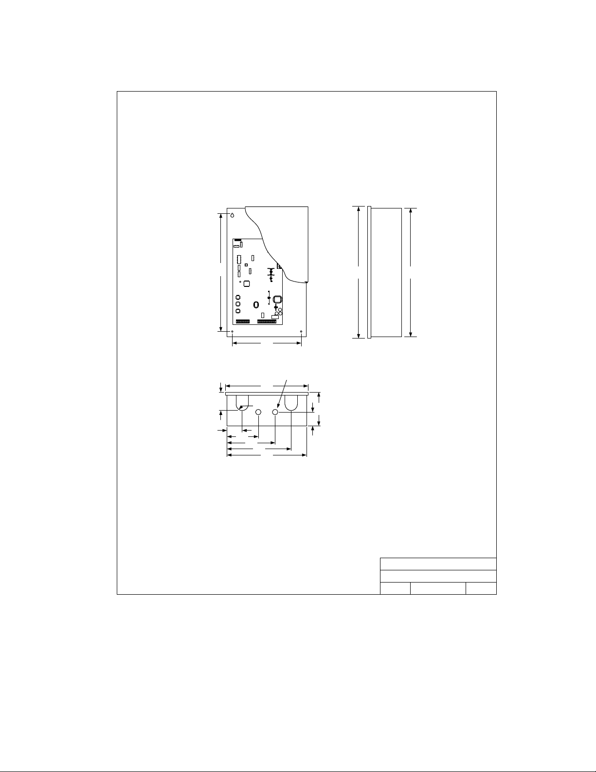
1.1.1 Main and Auxiliary Cabinets
33.0
11.25
.875 KO
2-places
13.25
3.0
1.0 R
2.5
5.125
7.875
10.5
13.0
5.125
2.25
35.25
35.0
DOORKING, INC., INGLEWOOD, CA 90301
Main Cabinet / Auxiliary Cabinet - Large
Title:
P/N 1820-080 / 1820-081
Date: Rev.Dwg. No.
M1820-065-14/05
A
Page 10 1820-065-E-12-11
Page 11
1.1.2 Garden Style Cabinet
19.0
11.25
.875 KO
2-places
13.25
3.0
1.0 R
2.5
5.125
7.875
10.5
13.0
5.125
2.25
21.25
21.0
DOORKING, INC., INGLEWOOD, CA 90301
Garden Style Cabinet
Title:
P/N 1816-082, 1820-082, 1820-083
Date: Rev.Dwg. No.
M1820-065-29/04
A
1820-065-E-12-11 Page 11
Page 12
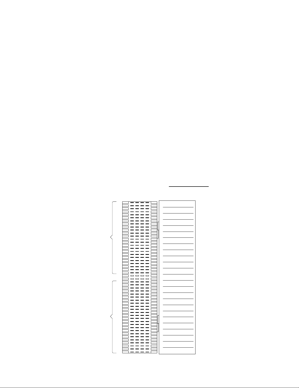
1.2 RJ71C Phone Block Installation
The RJ71C wiring configuration is not recognized by all telephone companies. For Bell Canada,
which has jurisdiction for Ontario and Quebec, refer to CA-79X jack for interconnect to the 1820
system. For BC Tel, which has jurisdiction in British Columbia, refer to BC Tel CRTC Spec 182 B5.
1. Place the order for the RJ71C phone block installation with the local telephone
company at least three weeks in advance of the 1820 system installation.
2. Order one (1) RJ71C block for every 12 telephone lines that the 1820 system will
inter-connect with.
3. Have all required blocks installed in a common accessible location. This is usually
near the original phone company termination board.
4. Be sure there the RJ71C blocks are mounted within 15 feet of where the main and
auxiliary cabinet(s) are to be installed. The standard length connecting cable
supplied by DoorKing is 15 feet. If longer cables are required, special length cables
will have to be ordered at an additional cost.
5. IMPORTANT!! Complete the RJ71C block identification form in the back of this
manual. This form instructs the telephone company installer how the phone lines
should be wired to the RJ71C blocks. Make copies of the form if more are required.
6. IMPORTANT!! Be sure that the phone company installer labels the blocks! Each
block should be numbered, and the phone number and apartment number should be
written on the inside of the block cover (see example below).
7. Attach the RJ71C block identification form to the inside door of the 1820 cabinet after
wiring is complete for future reference.
8. CALL DOWN!! For the call down feature and programming from the resident phone
to function, the resident must have active telephone service. If the resident does not
have active telephone service, then a special Powered RJ-71C
phone block is needed. See section 2.3 for detail.
Incoming
Central Office
Phone Lines
Not Used
Outgoing
Phone Lines
To Apartments
1
2
3
4
5
6
7
8
9
10
11
12
13
14
15
16
17
18
19
20
21
22
23
24
25
26
27
28
29
30
31
32
33
34
35
36
37
38
39
40
41
42
43
44
45
46
47
48
49
50
391-7723 Apt 23
1
722-9901 Apt 24
2
551-9920 Apt 25
3
330-8965 Apt 26
4
882-9907 Apt 27
5
843-0041 Apt 28
6
992-9991 Apt 29
7
630-0084 Apt 30
8
212-2221 Apt 31
9
990-0218 Apt 32
10
670-6791 Apt 33
11
530-0558 Apt 34
12
13
14
15
16
17
18
19
20
21
22
23
24
25
(P/N 1820-047)
Page 12 1820-065-E-12-11
Page 13
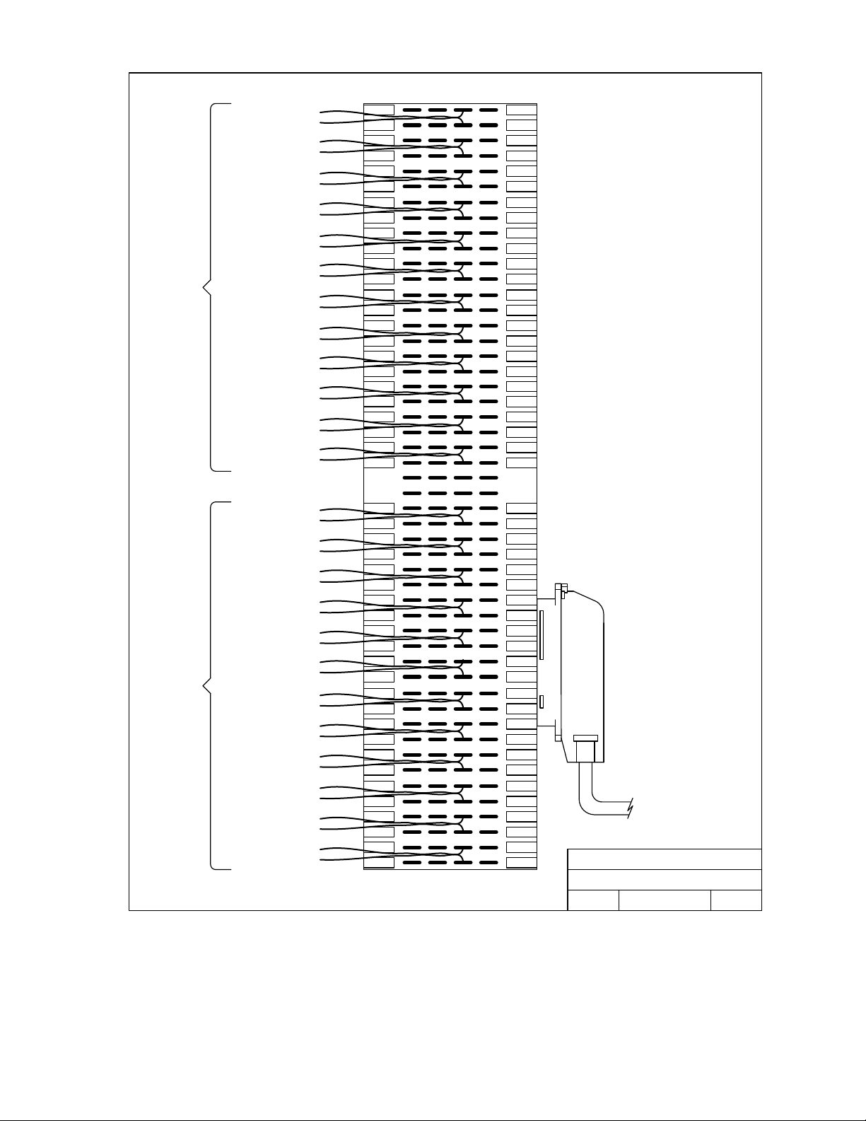
Incoming Central Office
Outgoing Phone Lines
Phone Lines - 12 Max
to Apartments
Line 1 TIP - Pin 1
Line 1 RING - Pin 2
Line 2 TIP - Pin 3
Line 2 RING - Pin 4
Line 3 TIP - Pin 5
Line 3 RING - Pin 6
Line 4 TIP - Pin 7
Line 4 RING - Pin 8
Line 5 TIP - Pin 9
Line 5 RING - Pin 10
Line 6 TIP - Pin 11
Line 6 RING - Pin 12
Line 7 TIP - Pin 13
Line 7 RING - Pin 14
Line 8 TIP - Pin 15
Line 8 RING - Pin 16
Line 9 TIP - Pin 17
Line 9 RING - Pin 18
Line 10 TIP - Pin 19
Line 10 RING - Pin 20
Line 11 TIP - Pin 21
Line 11 RING - Pin 22
Line 12 TIP - Pin 23
Line 12 RING - Pin 24
Line 1 TIP - Pin 27
Line 1 RING - Pin 28
Line 2 TIP - Pin 29
Line 2 RING - Pin 30
Line 3 TIP - Pin 31
Line 3 RING - Pin 32
Line 4 TIP - Pin 33
Line 4 RING - Pin 34
Line 5 TIP - Pin 35
Line 5 RING - Pin 36
Line 6 TIP - Pin 37
Line 6 RING - Pin 38
Line 7 TIP - Pin 39
Line 7 RING - Pin 40
Line 8 TIP - Pin 41
Line 8 RING - Pin 42
Line 9 TIP - Pin 43
Line 9 RING - Pin 44
Line 10 TIP - Pin 45
Line 10 RING - Pin 46
Line 11 TIP - Pin 47
Line 11 RING - Pin 48
Line 12 TIP - Pin 49
Line 12 RING - Pin 50
10
11
12
13
14
15
16
17
18
19
20
21
22
23
24
27
28
29
30
31
32
33
34
35
36
37
38
39
40
41
42
43
44
45
46
47
48
49
50
A
1
2
3
4
5
6
7
8
9
D
CB
IMPORTANT!
When the phone wires are
punched down on ROW B,
bridge clips from row B to row
C must be installed. If the
phone wires are punched
down on row C, bridge clips
are not required.
IMPORTANT!
TIP (positive) RING (negative)
polarity MUST be observed.
TIP must be punched down on
the top terminal of each pair
and RING must be punched
down on the bottom terminal
of each pair.
NOTE:
The RJ71C wiring configuration is not
recognized by all telephone companies.
For Bell Canada, which has
jurisdiction in Ontario and Quebec,
refer to CA-79X
For BC Tel, which has jurisdiction in
British Columbia, refer to BC Tel
CRTC Spec 182 B5.
To Line
Interface or
Relay Board
DOORKING, INC., INGLEWOOD, CA 90301
Detail Wiring - RJ71C Phone Block
Title:
Date: Dwg. No.
5/11
M1816-065-6
Rev.
D
1820-065-E-12-11 Page 13
Page 14
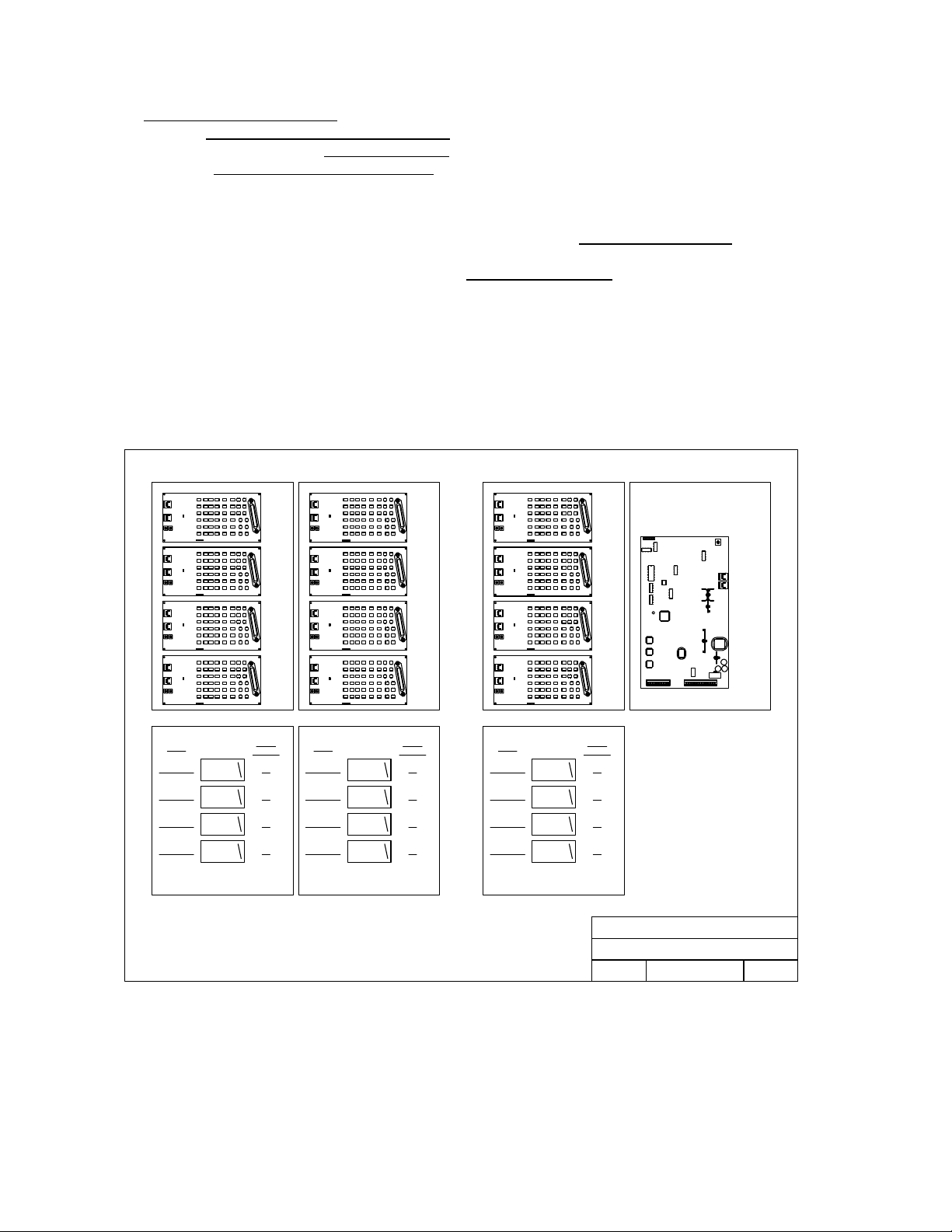
1.3 Cabinet, Relay and Component Identification
The Large Main Control Cabinet houses the main processor control board and up to 9 line interface
boards. The Garden Style Main Control Cabinet
4 line interface boards. Large Auxiliary Cabinets
supply board. Garden Style Auxiliary Cabinets
1.3.1 Main Control Cabinet Options
If the 1820 system is interfacing with 48 or less phone lines, the Garden Style Cabinet is typically
used since no auxiliary cabinets will be required. If the 1820 system is interfacing with more than 48,
but less than 108 phone lines, then the larger 1820 Main Control Cabinet
1.3.2 Auxiliary Cabinet Options
Either garden style or large type cabinets can be used to hold additional line interface boards as
required by the number of phone lines the system needs to interface with. The Garden Style Cabinet
can hold up to 8 line interface boards, or 7 line interface boards and 1 power supply board. The
Large Auxiliary Cabinet can hold up to 12 line interface boards and a power supply board.
houses the main processor control board and up to
can hold up to 12 line interface boards and a power
can hold up to 8 line interface boards.
will be used.
Relay
0132-0143
0120-0131
0108-0119
0096-0107
Board 11
Board 10
Board 9
Board 8
Board
Board
Board
Board
Board
Address
11
10
09
08
11
10
9
8
Relay
0084-0095
0072-0083
0060-0071
0048-0059
Board 7
Board 6
Board 5
Board 4
Board
Board
Board
Board
Board
Address
07
06
05
04
Board
7
3
Board
6
2
Board
5
1
Board
4
Relay
0036-0047
0024-0035
0012-0023
0000-0011
Board 3
Board 2
Board 1
Board 0
0
Board
Address
03
02
01
00
DOORKING, INC., INGLEWOOD, CA 90301
Main Cabinet / Auxiliary Cabinet - Small
Title:
Board Layout
Date: Rev.Dwg. No.
M1820-065-44/05
A
Page 14 1820-065-E-12-11
Page 15
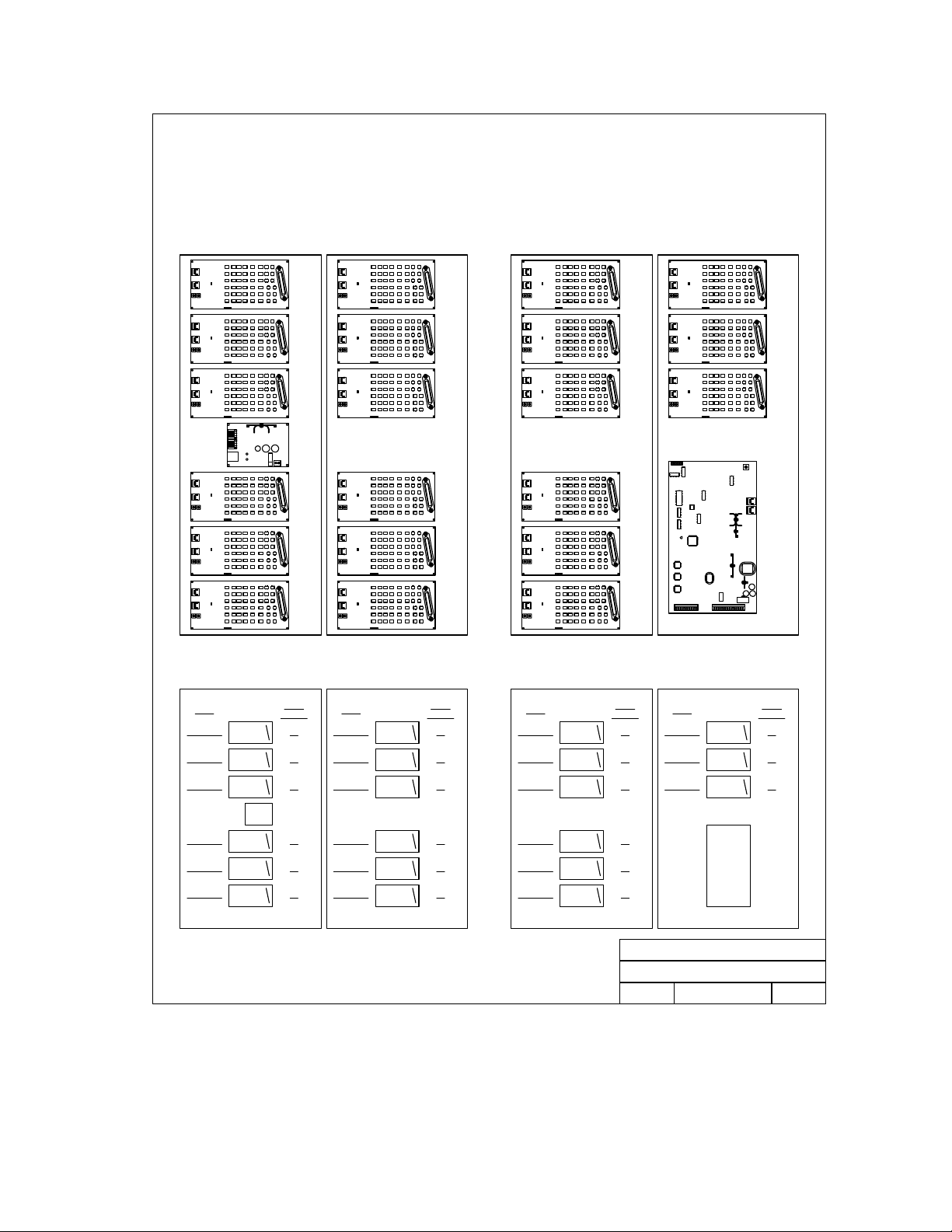
Relay
0240-0251
Board 20
Board
Board
Board
Board
Board
Board
Board
Address
20
20
19
18
17
16
15
Relay
0168-0179
Board 14
Board
Board
Board
Board
Board
Board
Board
Address
14
14
13
12
11
10
9
Relay
0096-0107
Board
Board
Board
Board
Board
Board
Board
Address
08
Board
8
2
Board
7
1
Board
6
0
5
4
3
Relay
0024-0035
Board
Address
Board 2Board 8
02
0228-0239
0216-0227
0204-0215
0192-0203
Board 19
Board 18
Power
Module
Board 17
Board 16
Board 15
19
0156-0167
18
0144-0155
17
0132-0143
16
0120-0131
150180-0191
Board 13
Board 12
Board 11
Board 10
0012-0023
13
12
11
10
090108-0119
0084-0095
0072-0083
0060-0071
0048-0059
Board 7
Board 6
Board 5
Board 4
Board 3Board 9
07
0000-0011
06
05
04
030036-0047
DOORKING, INC., INGLEWOOD, CA 90301
Main Cabinet / Auxiliary Cabinet - Large
Title:
Board Layout
Date: Rev.Dwg. No.
Board 1
Board 0
M1820-065-34/05
01
00
A
1820-065-E-12-11 Page 15
Page 16
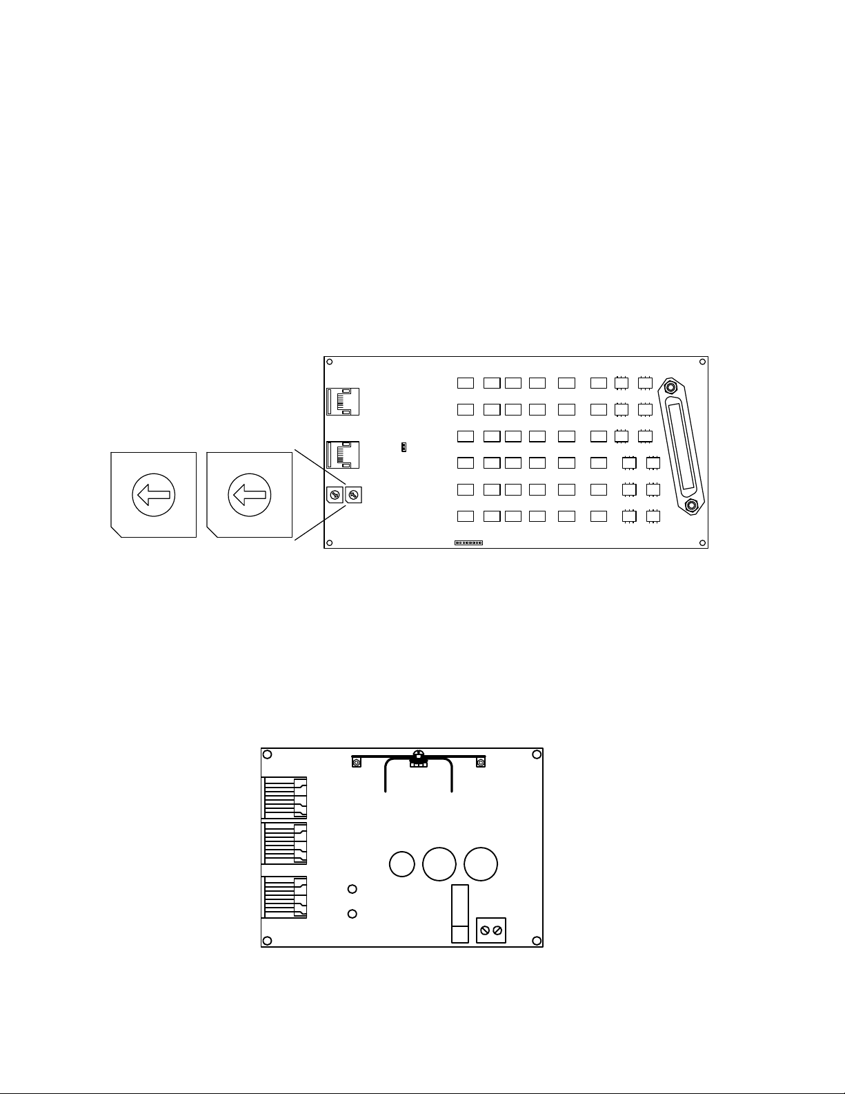
1.3.3 Line Interface Boards
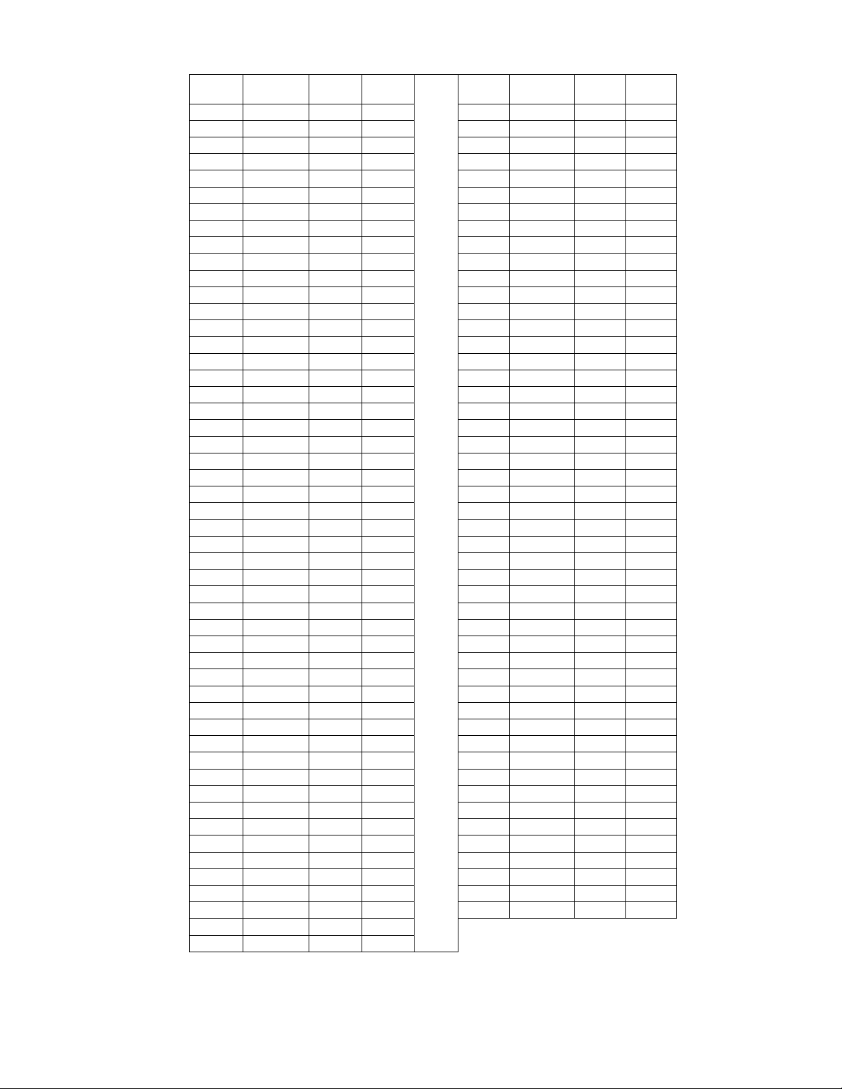
Each Line Interface Board has 12 relays on it that are referred to as relays 00 through 11. One line
interface board is required for every 12 phone lines that the system interfaces with. These relays are
identified to the main processor as a four digit relay number beginning with 0000 and increasing
sequentially up to the maximum of 1199. A maximum of 100 line interface boards can be installed
per system. Each cabinet has a label which identifies the cabinet number and the system relay
numbers.
Line interface boards in the main cabinet are numbered 0 – 2. Line interface board 0 is at the
bottom, line interface board 2 is at the top.
Each interface board is addressed using the two rotary switches on the board. The two 10
position switches allow for up to 100 board addresses starting at 00 and ending at 99. You
cannot skip an address location. For example, if you have 7 interface boards in the system,
the boards must be addressed from 00 (1
If a line interface board is replaced, be sure to set the address on the new board correctly.
Disconnect power to the main control board and then reapply for the change to take affect.
st
board) to 06 (7th board).
DOORKING 1884-010
3
2
4
1
0
9
5
6
7
8
3
2
4
1
0
9
5
6
7
8
1.3.4 Power Supply Boards
The main control board can supply power for up to 21 line interface boards located within 200 feet of
the main board. Additional line interface boards are powered by the addition of power supply boards,
each capable of supplying power for up to an additional 21 line interface boards.
If the distance from the main control board to the line interface boards exceeds 200 feet,
additional power supply boards will be required to supply power to the line interface boards.
1886-010
RELAY
OUTPUT
RELAY
OUTPUT
PWR
RLY
MAIN
INPUT
16.5 VAC
INPUT
Page 16 1820-065-E-12-11
Page 17
Board # Board
Address
0 00 0000 0011 51 51 0612 0623
1 01 0012 0023 52 52 0624 0635
2 02 0024 0035 53 53 0636 0647
3 03 0036 0047 54 54 0648 0659
4 04 0048 0059 55 55 0660 0671
5 05 0060 0071 56 56 0672 0683
6 06 0072 0083 57 57 0684 0695
7 07 0084 0095 58 58 0696 0707
8 08 0096 0107 59 59 0708 0719
9 09 0108 0119 60 60 0720 0731
10 10 0120 0131 61 61 0732 0743
11 11 0132 0143 62 62 0744 0755
12 12 0144 0155 63 63 0756 0767
13 13 0156 0167 64 64 0768 0779
14 14 0168 0179 65 65 0780 0791
15 15 0180 0191 66 66 0792 0803
16 16 0192 0203 67 67 0804 0815
17 17 0204 0215 68 68 0816 0827
18 18 0216 0227 69 69 0828 0839
19 19 0228 0239 70 70 0840 0851
20 20 0240 0251 71 71 0852 0863
21 21 0252 0263 72 72 0864 0875
22 22 0264 0275 73 73 0876 0887
23 23 0276 0287 74 74 0888 0899
24 24 0288 0299 75 75 0900 0911
25 25 0300 0311 76 76 0912 0923
26 26 0312 0323 77 77 0924 0935
27 27 0324 0335 78 78 0936 0947
28 28 0336 0347 79 79 0948 0959
29 29 0348 0359 80 80 0960 0971
30 30 0360 0371 81 81 0972 0983
31 31 0372 0383 82 82 0984 0995
32 32 0384 0395 83 83 0996 1007
33 33 0396 0407 84 84 1008 1019
34 34 0408 0419 85 85 1020 1031
35 35 0420 0431 86 86 1032 1043
36 36 0432 0443 87 87 1044 1055
37 37 0444 0455 88 88 1056 1067
38 38 0456 0467 89 89 1068 1079
39 39 0468 0479 90 90 1080 1091
40 40 0480 0491 91 91 1092 1103
41 41 0492 0503 92 92 1104 1115
42 42 0504 0515 93 93 1116 1127
43 43 0516 0527 94 94 1128 1139
44 44 0528 0539 95 95 1140 1151
45 45 0540 0551 96 96 1152 1163
46 46 0552 0563 97 97 1164 1175
47 47 0564 0575 98 98 1176 1187
48 48 0576 0587 99 99 1188 1199
49 49 0588 0599
50 50 0600 0611
1st
Relay
Last
Relay
Board # Board
Address
1st
Relay
Last
Relay
1820-065-E-12-11 Page 17
Page 18

Page 18 1820-065-E-12-11
Page 19

Section 2 - Wiring
Prior to installing wiring to the telephone entry system, we suggest that you become familiar with the
instructions, illustrations, and wiring guidelines in this manual. This will help insure that you
installation is performed in an efficient and professional manner. This telephone entry system
contains a number of static sensitive components that can be damaged or destroyed by static
discharges during installation or use. Discharge any static prior to removing the circuit board from the
lobby panel by touching a proper ground device.
The wiring of the telephone entry panel is an extremely important and integral part of the
overall access control system. Use proper wire for the communication line, power wires, and
be sure that the system is properly grounded. Check all local building ordinances and
building codes prior to installing this system. Be sure your installation is in compliance with
local codes.
Use only the supplied transformers (or U.L. listed equivalent) to power the telephone entry system
(16.5 VAC, 50 VA). Do not power any other devices (electric strikes, magnetic locks, etc.) from this
power transformer. For wire runs up to 100 feet, use 18 AWG, 600 volt insulated wire. For wire runs
up to 200 feet, use 16 AWG, 600 volt insulated wire.
Use 18 AWG wire for power runs up to 100 feet.
Use 16 AWG wire for power runs up to 200 feet.
Surge protection is recommended. Use DKS P/N 1878-010 or equivalent.
Use only twisted pair wires for phone line wiring. 24 AWG for up to 800 feet; 22 AWG up to
1600 feet.
Electric strikes, magnetic locks, etc., must be powered by a separate power transformer.
Lobby panels are powered from a separate power transformer.
This telephone intercom system requires the use of RJ71C phone blocks. We recommend that you
have the local telephone company install these blocks for you. One RJ71C must be ordered for every
12 phone lines (or fraction there of) that the 1820 will interface with. Give the telephone company
plenty of advance notice of when you will need the blocks installed. You must complete the RJ71C
block identification form(s) in the back of this manual. This is very important as it instructs the phone
company installer how the phone lines should be wired to the RJ71C. Be sure that the phone
company installer labels the blocks. Each block should be numbered, and the telephone number and
apartment number should be written on the inside of the block cover (see example on page xx).
When the phone company installer has completed the RJ71C block identification form(s), attach the
form to the inside of the 1816 cabinet for future reference.
The RJ71C wiring configuration is not recognized by all telephone companies. For Bell Canada
(Ontario, Quebec), refer to CA-79X block for interconnection to the 1816 system. For BC Tel (British
Columbia), refer to BC Tel CRTC Spec 182 B5.
Lobby panels come with their own wiring diagrams. The only connection between the 1820 and the
lobby panel is a twisted pair telephone wire.
1820-065-E-12-11 Page 19
Page 20
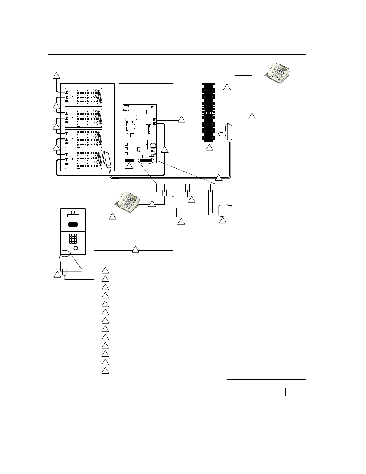
2.1 Wiring Detail – Garden Style Cabinet
1820 Telephone Intercom System
Wiring Detail - Garden Style Control Cabinet
13
12
12
12
7
Lobby Panel
Doorman Telephone
4
INCOMING
C.O. PHN
LINES
Resident
9
13
12
17 21151413 20191811 12 16 23 2422
6
C.O.
PHN
3
8
11
2
16 VAC
PWR
INPUT
1
10
Telephone
6
431 2
5
16 Volt, 50 VA UL Listed Transformer.
1
Earth Ground.
2
Optional Central Office phone line - touch tone, loop start.
3
Doorman / Concierge Telephone (Optional).
4
Lobby panel. Connect additional lobby panels in parallel. Refer to lobby panel installation manual for
5
additional wiring requirements.
Use twisted pair wires for phone connections. 24 AWG up to 800 feet; 22 AWG up to 1600 feet.
6
Decoder board terminals. Used with 1816 systems only.
7
RJ71C phone block. See drawing M1816-065-6 for detail.
8
Incoming phone lines from Central Office.
9
Outgoing phone lines to individual apartments.
10
DoorKing connecting cable.
11
RS-485 connecting cable.
12
To additional Line Interface Boards
13
Garden Style Cabinet
Title:
Wiring Detail
Date: Rev.Dwg. No.
DOORKING, INC., INGLEWOOD, CA 90301
M1820-065-54/05
A
Page 20 1820-065-E-12-11
Page 21
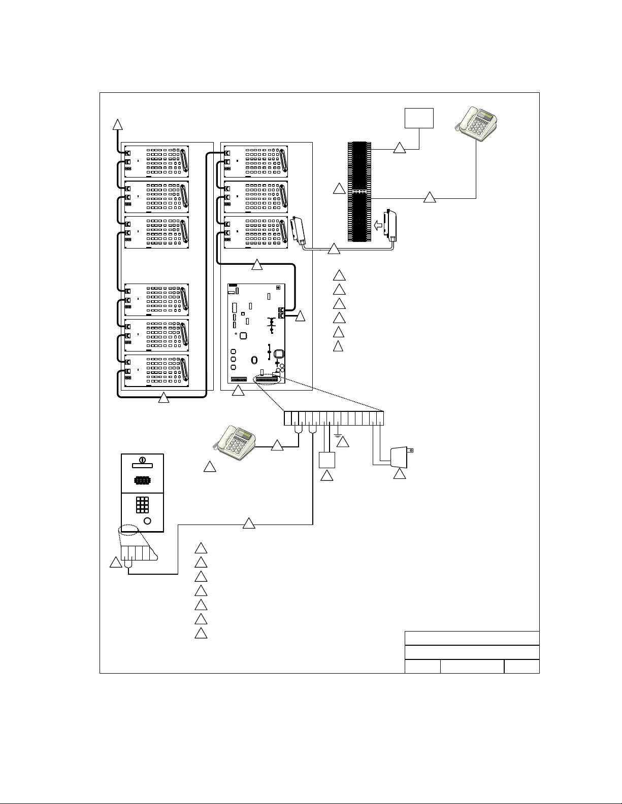
2.2 Wiring Detail – Large Main Cabinet
1820 Telephone Intercom System
Wiring Detail - Large Control Cabinet
13
12
INCOMING
C.O. PHN
LINES
9
8
11
12
13
7
RJ71C phone block. See drawing M1816-065-6 for detail.
8
Incoming phone lines from Central Office.
9
Outgoing phone lines to individual apartments.
10
DoorKing connecting cable.
11
RS-485 connecting cable.
12
To additional Line Interface Boards
13
10
Resident
Telephone
5
Lobby Panel
4312
17 21151413 20191811 12 16 23 2422
C.O.
PHN
2
3
16 VAC
PWR
INPUT
1
DOORKING, INC., INGLEWOOD, CA 90301
1820 Telephone Intercom System
Title:
Wiring Detail
Date: Dwg. No.
4/05
6
Doorman Telephone
4
6
16 Volt, 50 VA UL Listed Transformer.
1
Earth Ground.
2
Optional Central Office phone line - touch tone, loop start.
3
Doorman / Concierge Telephone (Optional).
4
Lobby panel. Connect additional lobby panels in parallel. Refer to lobby panel installation manual for
5
additional wiring requirements.
Use twisted pair wires for phone connections. 24 AWG up to 800 feet; 22 AWG up to 1600 feet.
6
Decoder board terminals. Used with 1816 systems only.
7
M1820-065-6
Rev.
A
1820-065-E-12-11 Page 21
Page 22
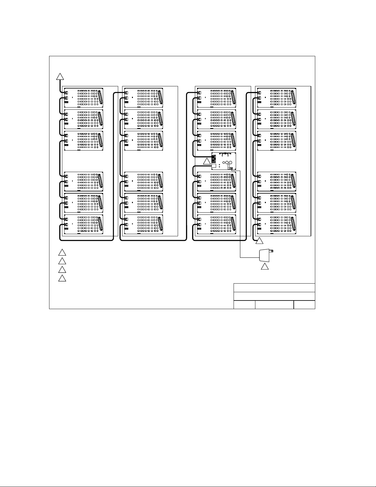
2.2.1 Wiring Detail – Auxiliary Cabinets
1820 Telephone Intercom System
Wiring Detail - Auxiliary Cabinets
3
4
16 Volt, 50 VA UL Listed Transformer.
1
From Preceding Line Interface Boards
2
To additional Line Interface Boards
3
Power Supply Board can power up to 21 additional Line Interface Boards. The power supply board is
4
only need if over 21 Line Interface Boards are used, or if they are located over 200 feet from the main
control babinet.
2
16 VAC
PWR
INPUT
1
DOORKING, INC., INGLEWOOD, CA 90301
1820 Telephone Intercom System
Title:
Wiring Detail Auxiliary Cabinets
4/05 M1820-065-7
Date: Rev.Dwg. No.
A
Page 22 1820-065-E-12-11
Page 23

2.3 Powered RJ-71C Wiring
For the Call Down feature and programming from a resident telephone to function in this system, the
resident must have an active Central Office (C.O.) phone line. The C.O. phone line provides the
power for these features to operate. If a resident does not have an active C.O. phone line, then a
special POWERED RJ-71C (P/N 1820-047) phone block will have to be used.
Depending on the application, some residents may have an active C.O. phone line while others may
not. You should also consider that this could change in the future. If a resident changes status of
having active C.O. phone service, or not having active C.O. phone service, the phone line will need to
be physically changed from a standard RJ-71C phone block to a powered RJ-71C phone block, and
vice-versa. There are two options for wiring a powered RJ-71C block into the system.
2.3.1 Dual Line Interface Board Option
Refer to drawing 1820-065-8.
Benefits:
Does not require moving any telephone company phone wiring.
Disadvantages:
Requires additional Line Interface Boards. This must be factored into the equipment list and
the hardware is configured.
Resident directory code / system relay number will change when phone wiring is removed.
If programmable directory codes are in use, the directory code will need to be reprogrammed.
Requires 1 extra Line Interface Board for every 12 phone lines without Central Office phone
service.
2.3.2 Dual RJ-71C Option
Refer to drawing 1820-065-9
Benefits:
Additional Line Interface Boards are not required.
Resident directory code / system relay number does not change.
Does not require reprogramming when a resident’s telephone service status changes.
Disadvantages:
Requires disconnect of the telephone company wiring.
1820-065-E-12-11 Page 23
Page 24
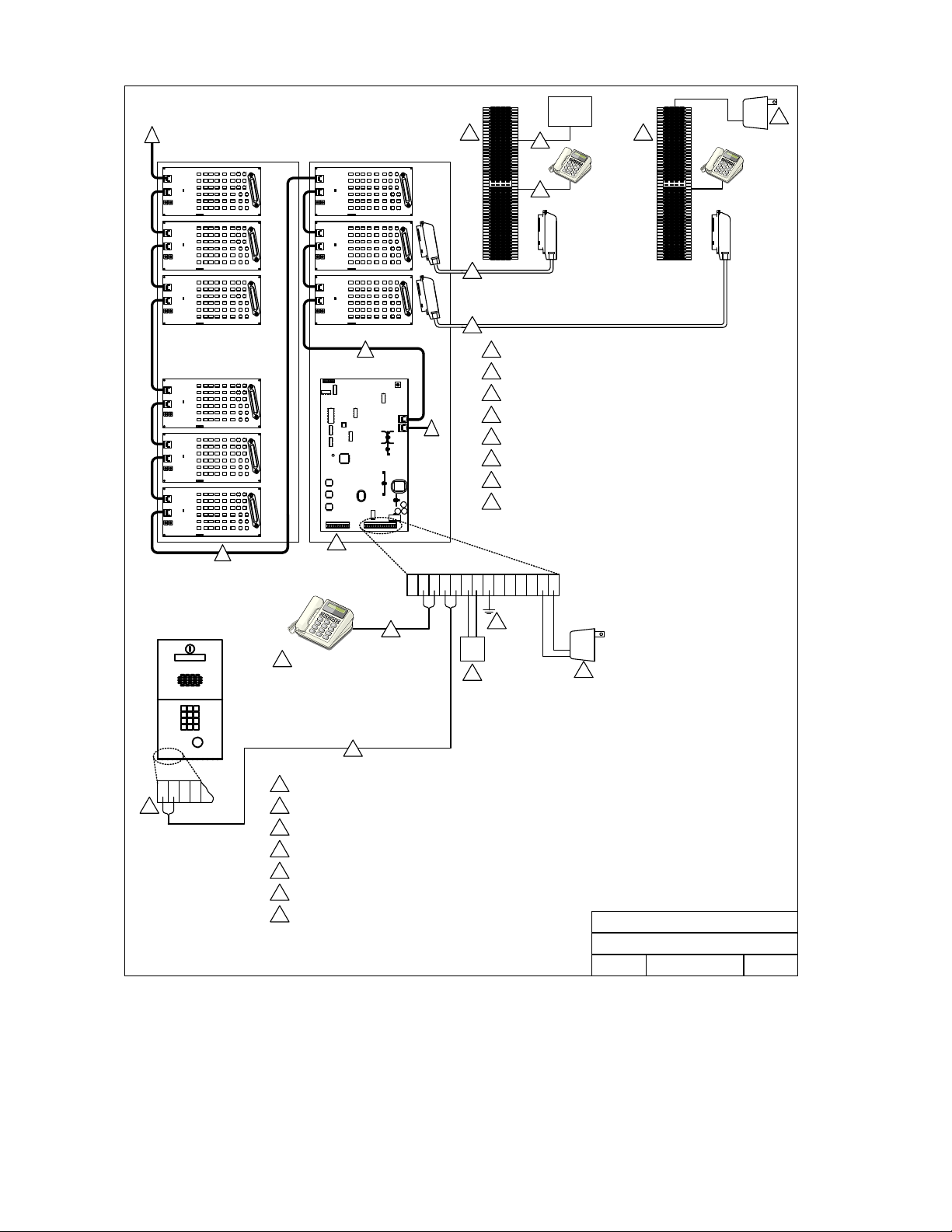
1820 Telephone Intercom System
Wiring Detail - Powered RJ-71C / Dual Interface Boards
13
12
INCOMING
C.O. PHN
8
11
11
RJ71C phone block. See drawing M1816-065-6 for detail.
8
Incoming phone lines from Central Office.
9
Outgoing phone lines to individual apartments.
10
DoorKing connecting cable.
13
11
RS-485 connecting cable.
12
To additional Line Interface Boards.
13
Powered RJ-71C phone b lock P/N 1820-047 for use only with residents
14
without active Central Office phone service.
12 VDC Regulated power supply.
15
LINES
9
10
Resident
Telephone
w/ Active
C.O. Line
14
12 VDC
Reg
Input
Resident
Telephone
without
C.O. Line
15
5
Lobby Panel
431 2
12
4
1
2
3
4
5
6
7
7
17 21151413 20191811 12 16 23 2422
6
Doorman Telephone
6
C.O.
PHN
2
3
16 VAC
PWR
INPUT
1
16 Volt, 50 VA UL Listed Transformer.
Earth Ground.
Optional Central Office phone line - touch tone, loop start.
Doorman / Concierge Telephone (Optional).
Lobby panel. Connect additional lobby panels in parallel. Refer to lobby panel installation manual for
additional wiring requir ements.
Use twisted pair wires for phone connections. 24 AWG up to 800 feet; 22 AWG up to 1600 feet.
Decoder board terminals. Used with 1816 systems only.
DOORKING, INC., INGLEWOOD, CA 90301
1820 Telephone Intercom System
Title:
Wiring Detail for Powered RJ-71C / Dual Boards
Date: Dwg. No.
4/05
M1820-065-8
Rev.
A
Page 24 1820-065-E-12-11
Page 25
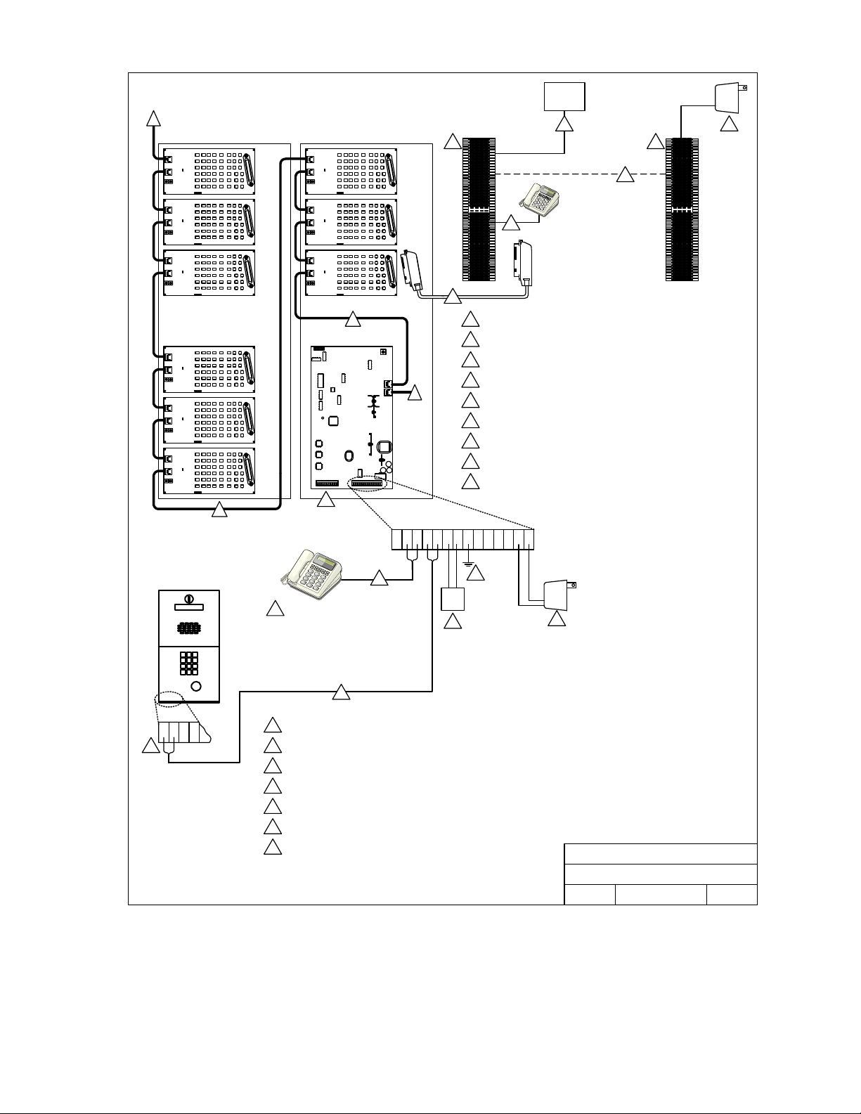
1820 Telephone Intercom System
Wiring Detail - Dual RJ-71C Option
13
12
INCOMING
C.O. PHN
LINES
9
8
Resident
Telephone
without
10
11
RJ71C phone block. See drawing M1816-065-6 for detail.
12
13
7
8
Incoming phone lines from Central Office.
9
Outgoing phone lines to individual apartments.
10
DoorKing connecting cable.
11
RS-485 connecting cable.
12
To additional Line Interface Boards.
13
Powered RJ-71C phone block P/N 1820-047 for use only with residents
14
without active Central Office phone service.
12 VDC Regulated power supply.
15
For residents without Central Office phone service, connect the powered
16
RJ-71C to the resident’s terminals.
C.O. Line
14
16
12 VDC
Reg
Input
15
5
Lobby Panel
431 2
17 21151413 20191811 12 16 23 2422
C.O.
PHN
2
3
16 VAC
PWR
INPUT
1
1820 Telephone Intercom System
Title:
Wiring Detail for Dual RJ-71C Option
Date: Dwg. No.
DOORKING, INC., INGLEWOOD, CA 90301
5/11
6
Doorman Telephone
4
6
16 Volt, 50 VA UL Listed Transformer.
1
Earth Ground.
2
Optional Central Office phone line - touch tone, loop start.
3
Doorman / Concierge Telephone (Optional).
4
Lobby panel. Connect additional lobby panels in parallel. Refer to lobby panel installation manual for
5
additional wiring requirements.
Use twisted pair wires for phone connections. 24 AWG up to 800 feet; 22 AWG up to 1600 feet.
6
Decoder board terminals. Used with 1816 systems only.
7
M1820-065-9
Rev.
B
1820-065-E-12-11 Page 25
Page 26
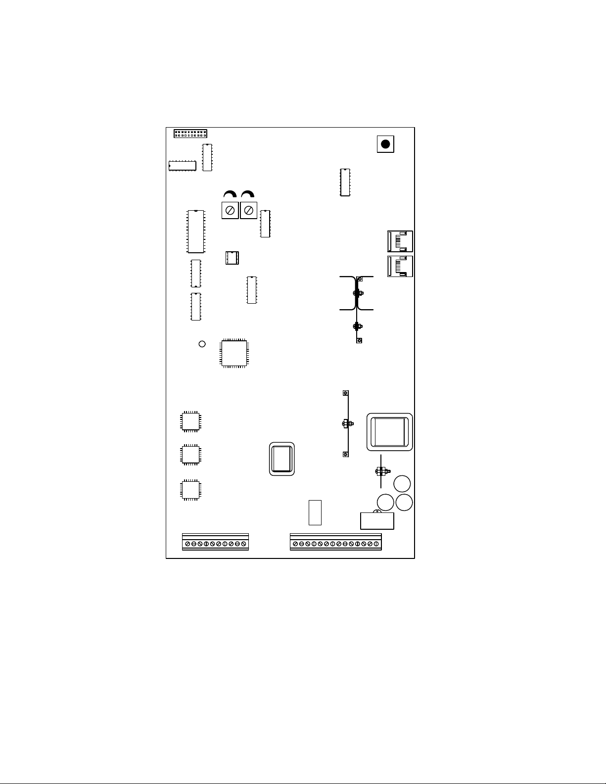
2.4 Circuit Board Connector Locations
10-Pin Ribbon Connector
Use with 1882 and 1982
(Standard) Relay Boards
1816 Systems only
ES OUT CO OUT
Master Code
Switch
RJ45 Jacks
Use with 1884 (Call Down)
Line Interface Boards
1820 Systems Only
Terminals 1-10
Decoder Board Connection
1816 Systems only
Main Terminals 11-24
Page 26 1820-065-E-12-11
Page 27
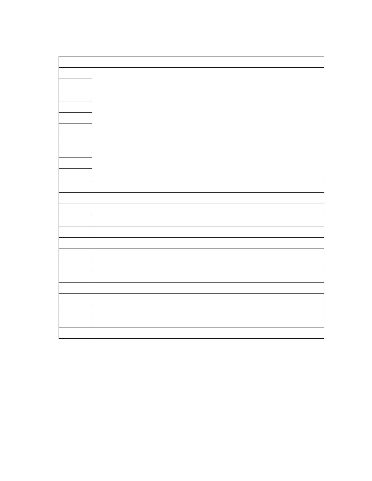
2.5 Main Circuit Board Terminal Description
Terminal Description
1
2
3
4
5
6
7
8
9
10
11 Postal Switch – A switch closure across terminals 11 and 24 will cause the relay on the 1885 board to
12
13
14
15
16
17
18
19
20
21
22
23
24
Decoder Board Connection. Decoder boards are required with 1816 systems that use more than 5 relay
boards.
activate for its programmed strike time.
Doorman / Concierge Telephone
Doorman / Concierge Telephone
Lobby Panel Entry System or Telephone
Lobby Panel Entry System or Telephone
Central Office Phone Line (Optional)
Central Office Phone Line (Optional)
Earth Ground
Relay Normally Closed (NC) Contact
Relay Normally Open (NO) Contact
Relay Common Contact
Not Used
16 VAC Main Cabinet Power Input
Low Voltage Common
1820-065-E-12-11 Page 27
Page 28

2.6 Entry System / Central Office Gain Adjustment
This section applies to 1885-010 REV S boards and higher.
These potentiometers are adjusted when more than one entry panel is attached to the 1816 system.
By default, both are set to the fully counter-clockwise (minimum gain) position and both should be left
in this position when a single entry panel is attached to the system.
ES OUT is used to adjust signal gain to the entry system lobby panel. The CO OUT is used to adjust
the gain of the signal going back to the C.O. Increasing the gain will increase the loudness.
Both should be left in the full counter-clockwise (least gain) position, unless it becomes necessary to
increase the gain (loudness) to the entry panel or out to the Central Office line. When adjusting the
gain, it may affect the echoing and may cause howling; therefore, small incremental adjustments
should be made to each potentiometer.
Master Code
Switch
ES OUT CO OUT
Page 28 1820-065-E-12-11
Page 29

Section 3 – Programming
3.1 System Set Up
The system has default settings for most programming functions. When installing a new system,
there is some set up programming required which will format the system to meet the operational
requirements of the installation. Once the system is set up, there are also operational programming
steps for the Doorman/Concierge phone and for tenant phones.
Programming steps for the 1820 set up are performed from the doorman/concierge phone or
from a standard touch tone phone connected to the lobby panel terminals (14-15). A “BEEP”
in the handset confirms that the programming step has been completed successfully. Do not
use a telephone with the keypad on the handset.
Resident telephones are addressed either by the system relay number or by a programmed
directory code. This is an either/or scenario. All residents will either use the default system
relay number or all residents will be assigned a programmed di rectory code.
The system wide commands that turn features ON/OFF can be very useful when
troubleshooting. These commands will not delete or erase any programmed information.
They simply disable the feature for system users.
It is highly recommended that you make a record of ALL programming completed. You can
complete the blanks in this instruction booklet and/or use the tables provided in the appendix
of this manual.
3.1.1 Master Code
This must be set at the 1885-010 Main Control Board. It is the “Password” utilized in all programming
steps.
Factory Default = 9999
1. Press the Master Code button on the main control board (upper right hand corner). The
power LED will start blinking slowly.
2. On the doorman telephone, enter a four-digit master code _ _ _ _ then press * (beep).
The LED will stop blinking.
3. Hang up to end the programming session.
3.1.2 1982 Relay Board / 1884 Interface Board
The 1885 main control board can be programmed to operate as an 1816 system utilizing the 1982
Relay Boards, or it can be programmed to operate as an 1820 system utilizing the 1884 Line
Interface Boards. This programming step tells the 1885 board which type system is in use and must
be programmed for 1884 Line Interface Boards with the 1820 system.
Factory Default = 0 (1982 Relay Boards) Enter “1” in step 3 for 1884 Line Interface Board.
1. Take the doorman telephone off hook.
2. Press *54 and enter the four-digit MASTER CODE _ _ _ _ (beep).
3. Enter 1 then press * (beep).
4. Hang up the doorman telephone to end the programming session.
1820-065-E-12-11 Page 29
Page 30
3.1.3 Last Available Relay
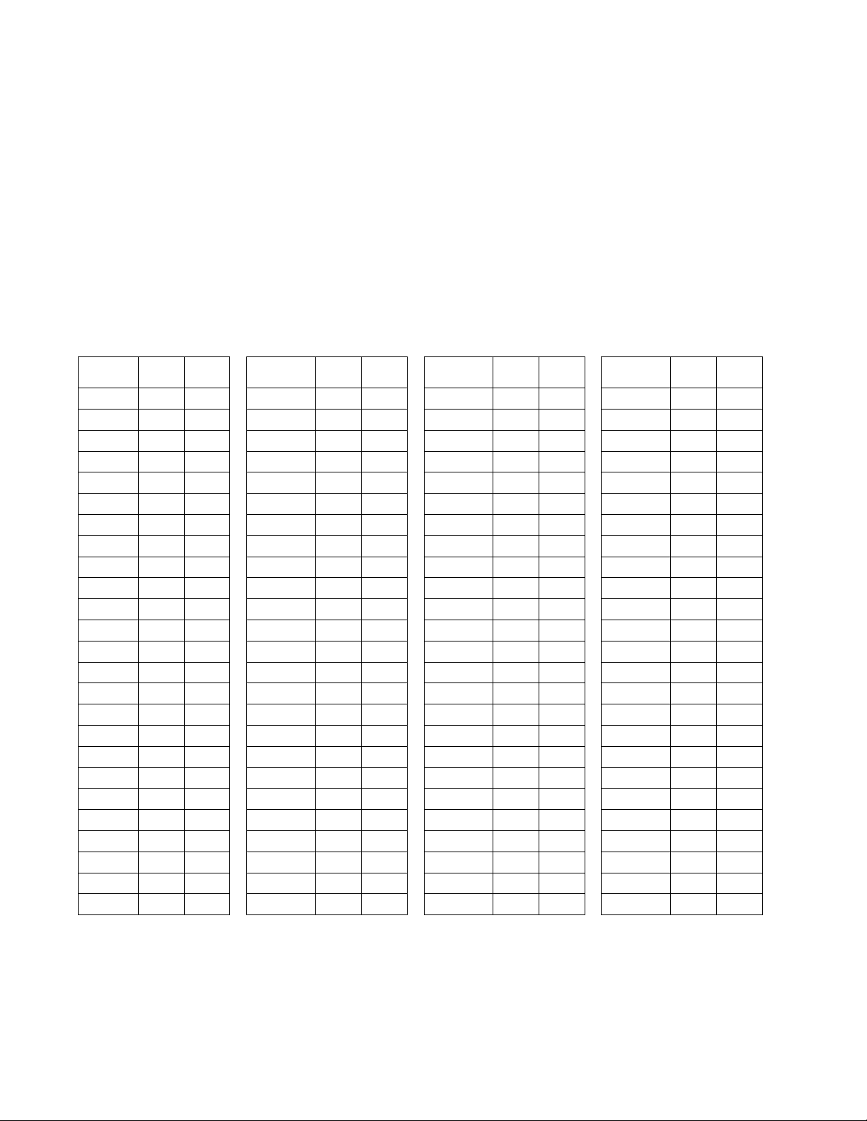
The 1820 is capable of working with up to 1200 telephones, i.e. it can select one of up to 1200
system relays that are numbered 0000 through 1199. You must program into the system the last
relay number that is available. Determine how many relay boards are connected to the system, then
using the chart below, select the last available relay. For example, if your system uses 55 relay
boards, the last relay available is 0671.
Factory Default = 0011
1. Take the doorman telephone off hook.
2. Press *07 and enter the four-digit MASTER CODE _ _ _ _ (beep).
3. Enter the four-digit last available relay number _ _ _ _ then press * (beep).
4. Hang up the doorman telephone to end the programming session.
Board
Number
0 0000 0011 0300 0311 0600 0611 0900 0911 25 50 75
1 0012 0023 26 0312 0323 51 0612 0623 76 0912 0923
2 0024 0035 27 0324 0335 52 0624 0635 77 0924 0935
3 0036 0047 28 0336 0347 53 0636 0647 78 0936 0947
4 0048 0059 29 0348 0359 54 0648 0659 79 0948 0959
5 0060 0071 30 0360 0371 55 0660 0671 80 0960 0971
6 0072 0083 31 0372 0383 56 0672 0683 81 0972 0983
7 0084 0095 32 0384 0395 57 0684 0695 82 0984 0995
8 0096 0107 33 0396 0407 58 0696 0707 83 0996 1007
9 0108 0119 34 0408 0419 59 0708 0719 84 1008 1019
10 0120 0131 35 0420 0431 60 0720 0731 85 1020 1031
11 0132 0143 36 0432 0443 61 0732 0743 86 1032 1043
12 0144 0155 37 0444 0455 62 0744 0755 87 1044 1055
13 0156 0167 38 0456 0467 63 0756 0767 88 1056 1067
14 0168 0179 39 0468 0479 64 0768 0779 89 1068 1079
15 0180 0191 40 0480 0491 65 0780 0791 90 1080 1091
16 0192 0203 41 0492 0503 66 0792 0803 91 1092 1103
17 0204 0215 42 0504 0515 67 0804 0815 92 1104 1115
18 0216 0227 43 0516 0527 68 0816 0827 93 1116 1127
19 0228 0239 44 0528 0539 69 0828 0839 94 1128 1139
20 0240 0251 45 0540 0551 70 0840 0851 95 1140 1151
21 0252 0263 46 0552 0563 71 0852 0863 96 1152 1163
22 0264 0275 47 0564 0575 72 0864 0875 97 1164 1175
23 0276 0287 48 0576 0587 73 0876 0887 98 1176 1187
24 0288 0299 49 0588 0599 74 0888 0899 99 1188 1199
1st
Relay
Last
Relay
Board
Number
1st
Relay
Last
Relay
Board
Number
1st
Relay
Last
Relay
Board
Number
1st
Relay
Last
Relay
Page 30 1820-065-E-12-11
Page 31

3.1.4 Setting the System Time Clock
This programming sequence sets the internal time clock in the 1820 system. (Note – if you only want
to set the time, you can stop after step 4).
Factory Default = (Not Programmed)
1. Take the doorman telephone off hook.
2. Press *33 and enter the four-digit MASTER CODE _ _ _ _ (beep).
3. Enter the hour and minutes (HHMM) _ _ _ _ then press * (beep).
4. Enter 0 for AM; or enter 1 for PM _ then press * (beep).
5. Enter the month, day and year (MMDDYY) _ _ _ _ _ _ then press * (beep).
6. Enter the day of the week (1=Sunday, 7=Saturday) _ then press *(beep).
7. Hang up the doorman telephone to end the programming session.
3.1.5 Set the Caller ID Number
The system will provide a Caller ID to the resident phone when a call is generated from either the
entry panel or the doorman/concierge phone. This is necessary because some telephones equipped
with caller ID functions will not work unless a phone number is displayed. The caller ID number may
be set to anything, it has no other function.
Factory Default = 1234567890
1. Take the doorman telephone off hook.
2. Press *41 and enter the four-digit MASTER CODE _ _ _ _ (beep).
3. Enter the 10-digit caller ID number _ _ _ _ then press * (beep).
4. Hang up the doorman telephone to end the programming session.
3.1.6 Set the Talk Time
Talk time is the length of time that the 1820 system will allow communication to take place before
disconnecting. Talk time is set using a three digit code to set the time in seconds. Talk time can be
set from 001 to 255 seconds.
NOTE: When a DoorKing lobby panel is connected to the system, talk time should be set to
255 seconds. The lobby panel talk time should be set to the desired time and will override the
talk time set here. Refer to the lobby panel programming instructions to set the lobby panel
talk time.
Factory Default = 060
1. Take the doorman telephone off hook.
2. Press *08 and enter the four-digit MASTER CODE _ _ _ _ (beep).
3. Enter the three-digit talk time in seconds (001 – 255) _ _ _ then press * (beep).
4. Hang up the doorman telephone to end the programming session.
1820-065-E-12-11 Page 31
Page 32
3.1.7 Number of Rings / Ring Type
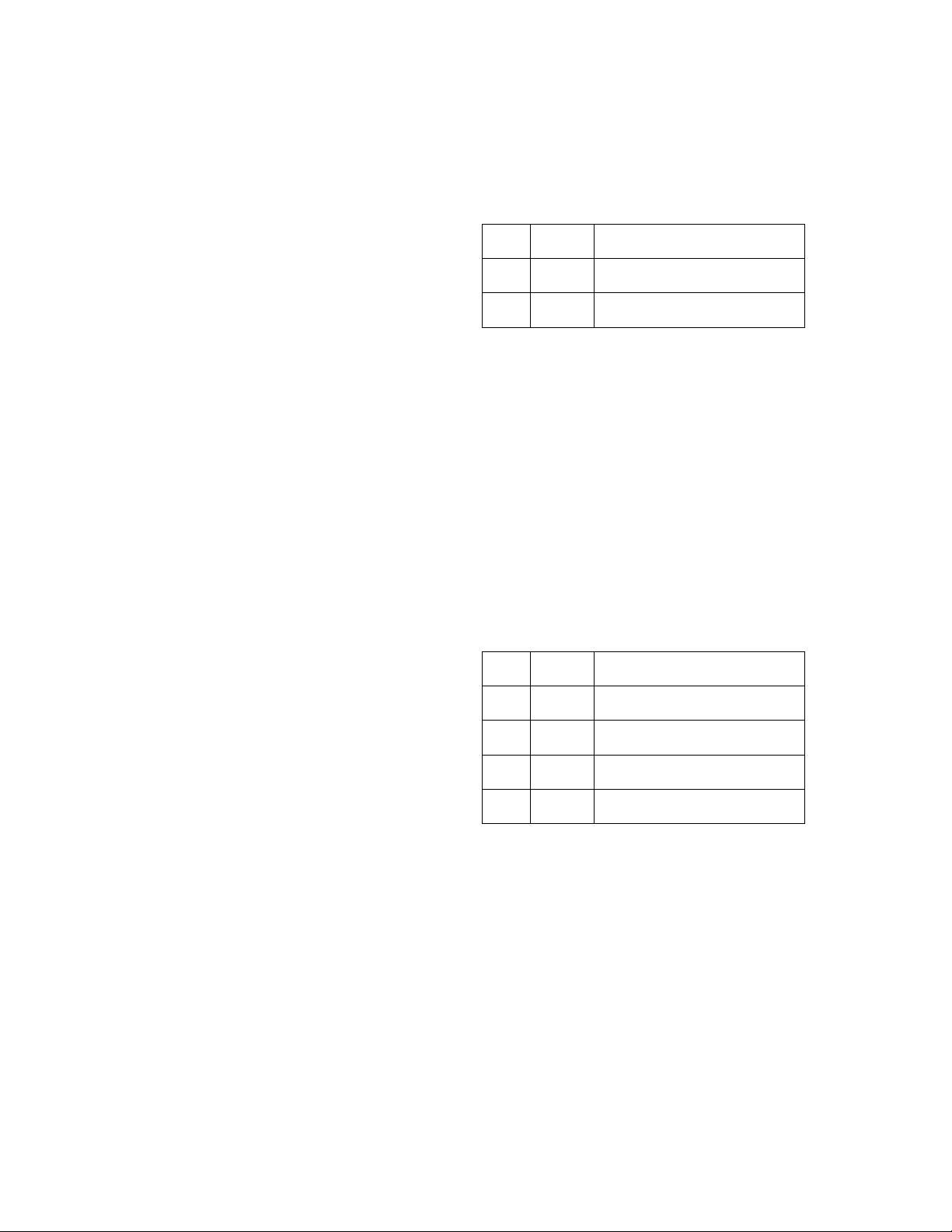
This programming sequence sets up the 1820 system for: 1) the number of rings allowed before the
system automatically hangs up if the call is not answered, 2) a single or double ring (when set for
double ring, the first ring will be a single ring). A two digit number will be entered to set up these
operating parameters, with each number of the code corresponding to the respective functions listed.
Factory Default = 31
1. Take the doorman telephone off hook.
2. Press *04 and enter the four-digit
MASTER CODE _ _ _ _ (beep).
Enter the two-digit ring/ring type code _ _
3.
then press * (beep).
4. Hang up the doorman telephone to end
Code
Number Description
Digit
1st 2 - 9
2nd 0 or 1
The number of rings before the
1820 automatically hangs up.
Enter 0 for a standard single ring,
or enter 1 for a double ring.
the programming session.
3.1.8 Tone Open Number Programming
The tone open number is the number that is pressed on the resident’s telephone to activate the relay
on the 1885 control board. The resident can only activate the relay momentarily, but other relay
functions are available from the doorman/concierge phone and by remote relay activation. The four
relay functions are: 1) momentary activation, 2) continuous activation (relay latch), 3) deactivation
(unlatch), 4) activate for one hour, then automatically deactivate. If a function is not going to be used,
enter a # sign in place of the respective digit. Do not use the number "3" as a tone open number
since this number is reserved to activate the call waiting feature. Do not duplicate tone open
numbers.
NOTE: When used with a DoorKing Lobby Panel, the 1820 and lobby panel Tone Open
Number programming must match. Refer to the lobby panel programming instructions to
program the lobby panel Tone Open Number programming.
Factory Default = 9 # # #
1. Take the doorman telephone off hook.
2. Press *05 and enter the four-digit
MASTER CODE _ _ _ _ (beep).
3. Enter the four-digit tone code _ _ _ _ then
press * (beep).
4. Hang up the doorman telephone to end
the programming session.
Code
Digit
1st
2nd
3rd
4th
Number Description
0, 1, 2,
4-9
Activate the relay for the
programmed strike time.
Acti
vates the relay continuously
(relay latch).
Deacti
vates the relay (relay
unlatch).
Acti
vates relay for 1-hour, then
automatically deactivates.
3.1.9 Relay Strike Time
The relay strike time is the amount of time that the relay on the 1885 control board will be energized
when activated by a tone open number, entry code number, or key switch (postal lock) input. Typical
strike time is 5 seconds for an electric st rike or magnetic lock release.
Factory Default = 01
1. Take the doorman telephone off hook.
2. Press *03 and enter the four-digit MASTER CODE _ _ _ _ (beep).
3. Enter the two-digit strike time code (00 – 99) _ _ then press * (beep). Note: 00 = ¼ sec.
4. Hang up the doorman telephone to end the programming session.
Page 32 1820-065-E-12-11
Page 33

3.2 Directory Codes
The four digit directory code is the number that is entered on the doorman/concierge or on the lobby
telephone keypad to communicate with a particular tenant in the building. The directory codes start at
0000 and increase sequentially up to the maximum number of relays being used in the system. For
example, if 100 residents are connected to the 1820 system, the directory codes being used will be
0000 for the first resident, up to 0099 for the 100th resident. Directory code 0000 activates system
relay 0000 and makes a connection to the resident connected to this relay, directory code 0001
activates system relay 0001 and makes a connection to the second resident, and so on.
The programmable directory code feature allows any four digit code between the numbers of 0000
and 3131 to be used as a resident’s directory code, regardless of which system relay the resident’s
telephone is connected to. For example, if a resident’s telephone line is connected to system relay
0000, that resident’s directory code can be programmed to any four digit number between 0000 and
3131. This feature is useful in applications, for instance, where apartment numbers are to be used as
the directory code number. Caution must be exercised to not duplicate any directory codes. Log all
directory codes entered into the system using the sample log sheet provided in the back of this
manual. Make copies of the log sheets if more are required. When the programmable directory
codes are turned "on", entering the programmed directory code will place the visitor in connection
with the resident’s telephone. Turning the programmable directory codes "off" requires that the
system relay number be entered on the keypad to contact a resident. See Operating Instructions for
more information.
3.2.1 Programming Directory Codes
These steps will allow the doorman/concierge to program directory codes for each resident. An 8digit code (XXXXYYYY) is entered, where the first 4 digits (X) represent the programmed directory
code and the last 4 digits (Y) represent the actual system relay number. For example, if directory
code 1234 is programmed to activate system relay 0219, then the 8-digit code is: 12340219. It is
suggested that you complete a log sheet with all the programmed codes showing which system relay
the programmed code activates. Programmable Directory Codes must be set to ON in step 3.2.2
for this to work.
NOTE: Entering 9 9 9 9 in the system relay number will cause the 1820 to do nothing. This may be
desired if for some reason certain system relays will not be used. For example, if 1 2 3 4 9 9 9 9 is
entered in step 3, dial tone will be heard on the lobby panel speaker when 1 2 3 4 is entered on the
lobby panel keypad. The visitor can then press any key to hang up the system.
NOTE: When programmable directory codes are used, all programming in any other
programming function should use the programmed directory code and not the relay number.
Factory Default = (Not Programmed)
1. Take the doorman telephone off hook.
2. Press *14 and enter the four-digit MASTER CODE _ _ _ _ (beep).
3. Enter the eight-digit code _ _ _ _ _ _ _ _ then press * (beep).
4. Repeat step 3 to enter additional programmed directory codes. Remember to press *
after each code entered.
5. Hang up the doorman telephone to end the programming session.
1820-065-E-12-11 Page 33
Page 34

3.2.2 Turning Programmable Directory Codes On / Off
The programmable directory codes can be turned "ON" or "OFF" after they have been programmed.
It will be necessary to turn this feature off if any trouble shooting of the system is ever required.
Turning the programmable directory code feature off does not cause the system to erase any
directory codes that have been previously programmed.
Factory Default = 1 (Off)
1. Take the doorman telephone off hook.
2. Press *13 and enter the four-digit MASTER CODE _ _ _ _ (beep).
3. Press 1 to turn this feature OFF; or press 0 to turn this feature ON then press * (beep).
(1 = system will use system relay number for resident identification. 0 = each resident
will be assigned a directory code.)
4. Hang up the doorman telephone to end the programming session.
3.2.3 Directory Code for Doorman/Concierge to Lobby Panel
This programmed directory code is used to initiate calls from the lobby panel directly to the
doorman/concierge phone and vise-versa. Code must be between 4000 and 9999. Be sure that you
do not duplicate outside line access codes (see section 3.3).
Factory Default = (Not Programmed)
1. Take the doorman telephone off hook.
2. Press *18 and enter the four-digit MASTER CODE _ _ _ _ (beep).
3. Enter a four-digit code (4000 – 9999) _ _ _ _ then press * (beep).
4. Hang up the doorman telephone to end the programming session.
3.2.4 Erasing All Programmed Directory Codes
This programming sequence will erase ALL programmed directory codes from the system. This
command can take as long as 20 seconds to complete. During the erasing process, short beeps will
be heard. When all directory codes are erased, a long beep will be heard. Caution – this
programming sequence is irreversible once it is started.
1. Take the doorman telephone off hook.
2. Press *15 and enter the four-digit MASTER CODE _ _ _ _ (beep).
3. Enter 9 9 9 9 then press * (a long beeeeeep will be heard when complete).
4. Hang up the doorman telephone to end the programming session.
Page 34 1820-065-E-12-11
Page 35

3.3 Dedicated Phone Line Access
An optional dedicated central office (C.O.) phone can be connected to the 1820 system. Connecting
a C.O. line to the system provides additional functions available to the doorman/concierge and the
lobby panel can be programmed to dial an outside line under certain circumstances. It also allows
remote programming via a PC and modem when using a DoorKing 1833, 1834, 1835 or 1837 as the
lobby panel.
3.3.1 Doorman/Concierge Outside Line Access
When the optional dedicated telephone line is connected to the 1820 system, the doorman may have
unrestricted use of this line. This requires an access code to be entered on the doorman phone each
time the doorman wants to access the outside line. Code must be between 4000 and 9999. Be sure
that you do not duplicate doorman/concierge or lobby panel codes (see section 3.2.3).
Factory Default = (Not Programmed)
1. Take the doorman telephone off hook.
2. Press *09 and enter the four-digit MASTER CODE _ _ _ _ (beep).
3. Enter a four-digit access code (4000 – 9999) _ _ _ _ then press * (beep).
4. Hang up the doorman telephone to end the programming session.
3.3.2 Preprogrammed Phone Numbers
When the optional dedicated telephone line is connected to the 1820 system, up to 10
preprogrammed telephone numbers can be stored in the system memory. Preprogrammed
telephone numbers can be up to 12 digits in length. These numbers can be called by entering a fourdigit code on the lobby panel telephone or the doorman/concierge telephone (see operating
instructions). Code must be between 4000 and 9999. Be sure that you do not duplicate
doorman/concierge or lobby panel codes (see section 3.2.3).
Factory Default = (Not Programmed)
1. Take the doorman telephone off hook.
2. Press *10 and enter the four-digit MASTER CODE _ _ _ _ (beep).
3. Enter a four-digit directory code (4000-9999) _ _ _ _ then press * (beep).
4. Enter the desired preprogrammed number (12 digits maximum), then press * (beep).
5. Repeat steps 3 – 4 to enter up to 9 preprogrammed numbers.
6. Hang up the doorman telephone to end the programming session.
1820-065-E-12-11 Page 35
Page 36

3.3.3 Erase Preprogrammed Phone Number
This sequence allows you to erase individual preprogrammed phone numbers.
Factory Default = (Not Programmed)
1. Take the doorman telephone off hook.
2. Press *11 and enter the four-digit MASTER CODE _ _ _ _ (beep).
3. Enter the four-digit directory code of the number to be erased (4000-9999) _ _ _ _ then
press * (beep).
4. Repeat steps 3 to erase additional numbers.
5. Hang up the doorman telephone to end the programming session.
3.3.4 Erase All Preprogrammed Phone Numbers
This sequence erases all 10 preprogrammed phone numbers.
Factory Default = (Not Programmed)
1. Take the doorman telephone off hook.
2. Press *17 and enter the four-digit MASTER CODE _ _ _ _ (beep).
3. Enter 9 9 9 9 then press * (beep).
4. Hang up the doorman telephone to end the programming session.
Page 36 1820-065-E-12-11
Page 37

3.4 Entry Codes
Entry codes are a four digit number (preceded by #) than can be entered on the Doorman telephone
keypad to gain access through the door or gate. When a programmed entry code is entered on the
Doorman telephone keypad, the relay on the 1820 control panel will activate for the programmed
strike time. The maximum number of entry codes that can be stored in the 1816 memory is 10,000.
Use the log sheet provided in the back of this manual to record your entries.
Skip this section if a DoorKing Lobby panel is used. Entry codes will be programmed directly into the
lobby panel memory, not the 1820 memory.
3.4.1 Programming Entry Codes
Entry codes can be any four digit combination.
Factory Default = (Not Programmed)
1. Take the doorman telephone off hook.
2. Press *02 and enter the four-digit MASTER CODE _ _ _ _ (beep).
3. Enter a four-digit entry code _ _ _ _ then press * (beep).
4. Repeat step 3 to enter additional entry codes.
5. Hang up the doorman telephone to end the programming session.
3.4.2 Erasing Individual Entry Codes
This sequence allows you to erase an individual entry code (or codes).
Factory Default = (Not Programmed)
1. Take the doorman telephone off hook.
2. Press *06 and enter the four-digit MASTER CODE _ _ _ _ (beep).
3. Enter the four-digit entry code to be erased _ _ _ _ then press * (beep).
4. Repeat step 3 to erase additional entry codes.
5. Hang up the doorman telephone to end the programming session.
3.4.3 Erasing All Entry Codes
This sequence will erase all entry codes that have been programmed into the system.
Factory Default = (Not Programmed)
1. Take the doorman telephone off hook.
2. Press *00 and enter the four-digit MASTER CODE _ _ _ _ (beep).
3. Enter 9 9 9 9 then press * (a long beeeeeep will be heard when complete – about 3
seconds).
4. Hang up the doorman telephone to end the programming session.
1820-065-E-12-11 Page 37
Page 38

3.5 Do Not Disturb Features / Commands
The Do Not Disturb feature provides time zones that prevents calls from the lobby panel to ring up to
a resident.
3.5.1 Do Not Disturb Feature On / Off – System Wide
This determines if the system will allow the do not disturb features to be active, or prohibits the do not
disturb features from functioning. This is a system wide programming step; either do not disturb
features are allowed for all residents or do not disturb features are prohibited for all residents.
Turning the do not disturb feature off will not erase any programmed do not disturb time zones.
Factory Default = 0 (Off)
1. Take the doorman telephone off hook.
2. Press *51 and enter the four-digit MASTER CODE _ _ _ _ (beep).
3. Enter 0 to turn do not disturb Off, or enter 1 to turn do not disturb On, then press * (beep).
4. Hang up the doorman telephone to end the programming session.
3.5.2 Set 1-Time Do Not Disturb Timer for Resident(s)
This is a one-time timer that will provide do not disturb for a specific resident for a specific amount of
time (1 to 99 hours). Once the timer expires, calls will be allowed to the resident. This is not a
schedule; the timer is simply turned on or off for a set period of time and will not repeat itself. The
resident may also set this timer from the apartment by using resident commands.
Note: If programmable directory codes are used, enter the directory code number instead of
the relay number in step 3.
Factory Default = 0 (Off)
1. Take the doorman telephone off hook.
2. Press *21 and enter the four-digit MASTER CODE _ _ _ _ (beep).
3. Enter the four-digit relay number of the resident the timer is being set for _ _ _ _ then
press * (beep). Note: entering 9 9 9 9 in this step will set the timer for all residents.
4. Enter 0 to turn the timer Off, or enter 1 to turn the timer On, then press * (beep). Note: if
0 is selected in this step, go to step 6 to end the programming session.
5. Enter the timer hours (01-99) _ _ then press * (beep).
6. Repeat steps 3-5 to program another resident.
7. Hang up the doorman telephone to end the programming session.
Page 38 1820-065-E-12-11
Page 39

3.5.3 Scheduled Do Not Disturb On / Off
This programming sequence is used by the doorman or system administrator to turn the
preprogrammed do not disturb schedule on or off. The resident can also turn this schedule on or off
from the apartment using resident commands.
Note: If programmable directory codes are used, enter the directory code number instead of
the relay number in step 3.
Factory Default = 0 (Off)
1. Take the doorman telephone off hook.
2. Press *22 and enter the four-digit MASTER CODE _ _ _ _ (beep).
3. Enter the four-digit relay number of the resident that the schedule is being administered
on for _ _ _ _ then press * (beep). Note: entering 9 9 9 9 in this step will turn the
schedule on for all residents.
4. Enter 0 to turn the schedule Off, or enter 1 to turn the schedule On, then press * (beep).
5. Hang up the doorman telephone to end the programming session.
3.5.4 Setting Do Not Disturb Schedule
This programming sequence is used by the doorman or system administrator to set a do not disturb
schedule for residents. This schedule must be set by the doorman, it cannot be set by the resident
from the resident’s apartment.
Note: If programmable directory codes are used, enter the directory code number instead of
the relay number in step 3.
Factory Default = 12:00 AM to 6:00 AM Sunday through Saturday
1. Take the doorman telephone off hook.
2. Press *23 and enter the four-digit MASTER CODE _ _ _ _ (beep).
3. Enter the four-digit relay number of the resident that the schedule is being set for _ _ _ _
then press * (beep). Note: entering 9 9 9 9 in this step will set the schedule on for all
residents.
4. Enter the beginning time in hours and minutes (HHMM) _ _ _ _ then press * (beep).
5. Enter 0 for AM, or 1 for PM _ then press * (beep).
6. Enter the ending time in hours and minutes (HHMM) _ _ _ _ then press * (beep).
7. Enter 0 for AM, or 1 for PM _ then press * (beep).
8. Enter the days of the week that the schedule will be active (Sunday = 1; Saturday = 7)
then press * (beep). Note: you can enter from 1 – 7 digits in this step. For example, if
the schedule is set for Monday, Wednesday and Friday, enter 2 4 6.
9. Repeat steps 3-8 to program another resident.
10. Hang up the doorman telephone to end the programming session.
1820-065-E-12-11 Page 39
Page 40

3.6 Call Forwarding Features / Commands
The Call Forwarding feature provides options that can forward lobby panel calls for a resident to a
forwarding number. There are several options available on how a call is forwarded and system
administrators should review all these options.
3.6.1 Set Up for Call Forwarding - System Wide
This determines how the call forwarding feature will function system wide. Four options are available:
0. Call forwarding is turned off.
1. Calls from the lobby panel to a resident are forwarded through the phone line connected
to the 1820 main control panel.
2. Calls from the lobby panel to a resident are forwarded through the phone line connected
to the 1820 main control panel but are restricted to preset area codes.
3. Calls from the lobby panel to a resident are forwarded through the resident’s own phone
line.
Factory Default = 0 (Off)
1. Take the doorman telephone off hook.
2. Press *45 and enter the four-digit MASTER CODE _ _ _ _ (beep).
3. Enter 0 or 1 or 2 or 3 _ then press * (beep).
4. Hang up the doorman telephone to end the programming session.
3.6.2 Call Forwarding On / Off per Resident
This programming sequence is used by the doorman or system administrator to turn call forwarding
on or off per resident. The resident can also turn call forwarding on or off from the apartment using
resident commands.
Note: If programmable directory codes are used, enter the directory code number instead of
the relay number in step 3.
Factory Default = 0 (Off)
1. Take the doorman telephone off hook.
2. Press *39 and enter the four-digit MASTER CODE _ _ _ _ (beep).
3. Enter the four-digit relay number of the resident that call forwarding is being administered
for _ _ _ _ then press * (beep). Note: entering 9 9 9 9 in this step will turn call forwarding
on for all residents.
4. Enter 0 to turn call forwarding Off, or enter 1 to turn call forwarding On, then press *
(beep).
5. Repeat steps 3 and 4 to program additional residents.
6. Hang up the doorman telephone to end the programming session.
Page 40 1820-065-E-12-11
Page 41

3.6.3 Program Call Forward Numbers
This programming sequence is used by the doorman or system administrator to program call forward
numbers for residents. If option 2 was selected in 3.6.1, then the area code will be checked to see if
it is allowable or not. If not allowed, the system will ring the resident’s phone. The resident can also
program the call forwarding number from the apartment.
Note: If programmable directory codes are used, enter the directory code number instead of
the relay number in step 3.
Factory Default = (Not Programmed)
1. Take the doorman telephone off hook.
2. Press *40 and enter the four-digit MASTER CODE _ _ _ _ (beep).
3. Enter the four-digit relay number of the resident that call forward number is being
programmed for _ _ _ _ then press * (beep).
4. Enter the call forward phone number (1 to 12 digits) then press * (beep).
5. Repeat steps 3 and 4 to program additional resident call forward numbers.
6. Hang up the doorman telephone to end the programming session.
3.6.4 Delete Call Forward Numbers
This programming sequence is used by the doorman or system administrator to delete call forward
numbers for residents.
Note: If programmable directory codes are used, enter the directory code number instead of
the relay number in step 3.
Factory Default = (Not Programmed)
1. Take the doorman telephone off hook.
2. Press *49 and enter the four-digit MASTER CODE _ _ _ _ (beep).
3. Enter the four-digit relay number of the resident that call forward number is being deleted
for _ _ _ _ then press * (beeeeeep). Note: entering 9 9 9 9 in this step will delete call
forwarding numbers for all residents. This command can take as long as 20 seconds to
complete. During the erasing process, short beeps will be heard. When all call
forwarding numbers are erased, a long beep will be heard.
4. Hang up the doorman telephone to end the programming session.
1820-065-E-12-11 Page 41
Page 42

3.6.5 Program Call Forward Allowed Area Codes
This programming sequence is used by the doorman or system administrator to limit which area
codes can be called when option 2 is selected in 3.6.1. This is a feature to prevent toll charges being
incurred on calls forwarded through the phone line connected directly to the 1820 control panel. If a
call forwarding area code does not match an area code programmed here, then the call is routed to
the resident’s phone. Up to 30 area codes can be stored in the 1820 memory. A long beep is heard
when the memory is full.
Factory Default = (Not Programmed)
1. Take the doorman telephone off hook.
2. Press *46 and enter the four-digit MASTER CODE _ _ _ _ (beep).
3. Enter a three-digit area code _ _ _ then press * (beep).
4. Repeat step 3 to program additional area codes.
5. Hang up the doorman telephone to end the programming session.
3.6.6 Delete Call Forward Allowed Area Codes
This programming sequence is used by the doorman or system administrator to delete area codes
from the allowed area code memory.
Factory Default = (Not Programmed)
1. Take the doorman telephone off hook.
2. Press *47 and enter the four-digit MASTER CODE _ _ _ _ (beep).
3. Enter a three-digit area code _ _ _ then press * (beep).
4. Repeat step 3 to delete additional area codes.
5. Hang up the doorman telephone to end the programming session.
3.6.7 Delete All Call Forward Allowed Area Codes
This programming sequence is used by the doorman or system administrator to delete all area codes
from the allowed area code memory.
Factory Default = (Not Programmed)
1. Take the doorman telephone off hook.
2. Press *48 and enter the four-digit MASTER CODE _ _ _ _ (beep).
3. Enter 9 9 9 9 then press * (beeeeeep). This process takes about 3 seconds to complete.
4. Hang up the doorman telephone to end the programming session.
Page 42 1820-065-E-12-11
Page 43

3.7 Virtual Doorman
The virtual doorman is an independent system that provides communication from the lobby area to a
company that provides doorman services. The virtual doorman service is completely separate from
the 1820 system and does not utilize the 1820 lobby panel or any communication circuits provided by
the 1820 system.
When virtual doorman service is active and a call is initiated from the 1820 lobby panel, the 1820 will
provide a dry relay contact to the virtual doorman system to activate the virtual doorman system. At
the same time, the 1820 will disconnect the lobby panel and hang up. The virtual doorman
equipment will provide all communication and door access for visitors.
3.7.1 Virtual Doorman On / Off – System Wide
This programming sequence is used by the doorman or system administrator to turn the virtual
doorman function On or Off and sets the 1885 on board relay to function as a virtual doorman relay or
a door strike relay.
Factory Default = 0 (Off)
1. Take the doorman telephone off hook.
2. Press *52 and enter the four-digit MASTER CODE _ _ _ _ (beep).
3. Enter 0 to turn virtual doorman Off, or enter 1 to turn virtual doorman On, then press *
(beep).
4. Hang up the doorman telephone to end the programming session.
3.7.2 Set Virtual Doorman Relay Strike Time
This programming sequence is used by the doorman or system administrator to set the strike time for
the virtual doorman activation relay. Strike time can be set from 1 to 99 seconds.
Factory Default = 01
1. Take the doorman telephone off hook.
2. Press *53 and enter the four-digit MASTER CODE _ _ _ _ (beep).
3. Enter a two-digit strike time (01-99) _ _ then press * (beep).
4. Hang up the doorman telephone to end the programming session.
3.7.3 Virtual Doorman On / Off per Resident
This programming sequence is used by the doorman or system administrator to turn virtual doorman
On or Off for each resident or for all residents. Entering 9 9 9 9 in this step will turn this feature on or
off for ALL residents. Resident’s can turn this on or off from the apartment using resident commands.
Note: If programmable directory codes are used, enter the directory code number instead of
the relay number in step 3.
Factory Default = 0 (Off)
1. Take the doorman telephone off hook.
2. Press *43 and enter the four-digit MASTER CODE _ _ _ _ (beep).
3. Enter the four-digit relay number of the resident that virtual doorman is being
administered for _ _ _ _ then press * (beep).
4. Enter 0 to turn virtual doorman Off, or enter 1 to turn virtual doorman On then press *
(beep).
5. Repeat steps 3 and 4 to administer virtual doorman for other residents.
6. Hang up the doorman telephone to end the programming session.
1820-065-E-12-11 Page 43
Page 44

3.8 Call-Down Features / Commands
The call-down feature in the 1820 allows resident’s to contact the doorman / concierge directly from
their apartment phone without having to dial a 7-digit phone number. It also provides residents with
various programming options that they can control directly from their apartment. There are two
modes of operation for the “Call-Down” feature.
Direct Connect: In this mode, a resident can call down to the Doorman and be connected
directly with the Doorman telephone. The Doorman simply answers the phone to speak with
the resident.
Call Back Mode: In this mode, the resident will call the Doorman and the call will
automatically be placed on a queue. The resident information is shown on the caller ID
display of the Doorman telephone. The Doorman then calls back the resident when he is
available. The system will automatically enter this mode when the Doorman phone is busy or
if the system is busy (another call in progress). The Doorman may also have the option of
putting the system into this mode either temporarily with a timer, or with an On / Off
command.
3.8.1 Call-Down Feature On / Off – System Wide
This determines if the system will allow the call-down features to be active, or prohibits the call-down
features from functioning. This is a system wide programming step; either the call-down features are
allowed for all residents or the call-down features are prohibited for all residents.
Factory Default = 1 (On)
1. Take the doorman telephone off hook.
2. Press *32 and enter the four-digit MASTER CODE _ _ _ _ (beep).
3. Enter 0 to turn call-down Off, or enter 1 to turn call-down On, then press * (beep).
4. Hang up the doorman telephone to end the programming session.
3.8.2 Set Doorman to Enable / Disable Direct Connect
This determines if the Doorman has the ability to enable and disable the Direct Connect Call-Down
function. If set to allow the Doorman to enable and disable the Direct Connect feature, this
programming step will also determine if the disable function is timer based (see 3.8.3) or is set for an
On / Off function.
Factory Default = 1 (Doorman disable is allowed), 0 (Disable timer is OFF)
1. Take the doorman telephone off hook.
2. Press *34 and enter the four-digit MASTER CODE _ _ _ _ (beep).
3. Enter 0 (Doorman CANNOT disable Direct Connect), or enter 1 (Doorman CAN disable
Direct Connect), then press * (beep).
4. Enter 0 for the Doorman disable to be toggle based (On / Off), or enter 1 for the Doorman
disable to be timer based, then press * (beep).
5. Hang up the doorman telephone to end the programming session.
Page 44 1820-065-E-12-11
Page 45

3.8.3 Set Direct Connect Disable Timer
If Doorman disable is allowed and the disable timer is On (see 3.8.2), then this programming step will
set the amount of time for the disable timer. When the timer expires, Direct Connect is restored. The
disable timer can be set from 1 (01) to 99 (99) minutes.
Factory Default = 30 (30 minutes)
1. Take the doorman telephone off hook.
2. Press *35 and enter the four-digit MASTER CODE _ _ _ _ (beep).
3. Enter a two-digit disable time (in minutes) _ _ , then press * (beep).
4. Hang up the doorman telephone to end the programming session.
3.8.4 Set Direct Connect Call-Down Number
This programming step sets the 1-digit number that the resident will use to call down to the Doorman /
Concierge telephone. The call-down number can be set from 0 – 9. Do not duplicate the 1-digit
resident programming number (see 3.8.5).
Factory Default = 7
1. Take the doorman telephone off hook.
2. Press *37 and enter the four-digit MASTER CODE _ _ _ _ (beep).
3. Enter the one-digit Direct Connect number _ then press * (beep).
4. Hang up the doorman telephone to end the programming session.
3.8.5 Set Resident Programming Number
This programming step sets the 1-digit number that the resident will use to enter a programming
mode to set various functions. The programming number can be set from 0 – 9. Do not duplicate the
1-digit resident Direct Connect number (see 3.8.4).
Factory Default = 8
1. Take the doorman telephone off hook.
2. Press *38 and enter the four-digit MASTER CODE _ _ _ _ (beep).
3. Enter the one-digit Direct Connect number _ then press * (beep).
4. Hang up the doorman telephone to end the programming session.
1820-065-E-12-11 Page 45
Page 46

Page 46 1820-065-E-12-11
Page 47

SECTION 4 – OPERATING INSTRUCTIONS
4.1 Administrator and Doorman Commands & Functions
These commands are used by the System Administrator, Doorman, Concierge or Security Desk to
access various features of the 1820 system.
4.1.1 Lobby Panel On / Off
This programming sequence is used by the doorman or system administrator to turn the lobby panel
On or Off.
Factory Default = 1 (On)
1. Take the doorman telephone off hook.
2. Press *12 and enter the four-digit MASTER CODE _ _ _ _ (beep).
3. Enter 0 to turn the lobby panel Off, or enter 1 to turn the lobby panel On, then press *
(beep).
4. Hang up the doorman telephone to end the programming session.
4.1.2 Calling the Lobby Panel
This programming sequence is used by the doorman or system administrator to place a call to the
lobby panel from the doorman telephone.
1. Take the doorman telephone off hook.
2. Enter the four-digit lobby panel directory code programmed in section 3.2.3.
3. The lobby panel will answer.
a. If a DoorKing 1830 series or “P” series lobby panel is used, the lobby panel will
answer with a 1 second tone. Once the tone is heard, press *16 and then enter
the four-digit lobby panel MASTER CODE _ _ _ _. This will open communication
between the lobby panel and doorman phone.
4. Hang up the doorman telephone to disconnect from the lobby panel.
4.1.3 Accessing the Outside Phone Line
A dedicated C.O. phone line must be connected to the 1820 control panel for this feature to be
operable.
1. Take the doorman telephone off hook.
2. Enter the four-digit outside line access code that was programmed in section 3.3.1. The
outside line dial tone will be heard allowing calls to me made.
4.1.4 Calling Preprogrammed Telephone Numbers
A dedicated C.O. phone line must be connected to the 1820 control panel for this feature to be
operable. Preprogrammed telephone numbers can be called from either the Doorman phone or the
lobby panel.
1. From either the lobby panel or doorman phone, enter the four digit access code of the
preprogrammed phone number you want to call. Refer to section 3.3.2.
1820-065-E-12-11 Page 47
Page 48

4.1.5 Calling the Doorman or Lobby Panel from an Off Site Location
A dedicated C.O. phone line must be connected to the 1820 control panel for this feature to be
operable. This feature allows managers to place a call to the Doorman or lobby panel from an off site
location.
To call the doorman phone:
1. Call the phone number of the C.O. line attached to the 1820 system. The 1820 will
answer with a short tone (beep).
2. Press #1 to be connected to the doorman phone.
3. The doorman phone will ring until it is picked up OR until the number of rings
programmed in section 3.1.7 is met.
To call the lobby panel:
1. Call the phone number of the C.O. line attached to the 1820 system. The 1820 will
answer with a short tone (beep).
2. Press #2 to be connected to the lobby panel.
a. If a DoorKing 1800 series, 1830 series or “P” series lobby panel is used, the
lobby panel will answer with a 1 second tone. Once the tone is heard, press *16
and then enter the four-digit lobby panel MASTER CODE _ _ _ _. This will open
communication to the lobby panel.
4.1.6 Lobby Panel Relay Activation
A dedicated C.O. phone line must be connected to the 1820 control panel for this feature to be
operable. This feature can only be used with DoorKing lobby panels.
1. Call the phone number of the C.O. line attached to the 1820 system. The 1820 will
answer with a short tone (beep).
2. Press #2 to be connected to the lobby panel.
3. The lobby panel will answer with a 1 second tone. Once the tone is heard, press *16 and
then enter the four-digit lobby panel MASTER CODE _ _ _ _. This will open
communication to the lobby panel.
4. Press “9” (or the number that has been programmed in the lobby panel to open the door).
4.1.7 Calling a Resident without C.O. Phone Service from an Off Site Location
A dedicated C.O. phone line must be connected to the 1820 control panel for this feature to be
operable. This feature allows managers to place a call to residents who do not have C.O. phone
service from an off site location.
1. Call the phone number of the C.O. line attached to the 1820 system. The 1820 will
answer with a short tone (beep).
2. Press #3 and enter the resident’s four digit directory code. The 1820 will connect to the
resident’s phone.
Page 48 1820-065-E-12-11
Page 49

4.1.8 Turn Direct Connect On / Off
This command allows the Doorman to disable the resident direct connect call down feature. When
disabled, this feature is either timer based or can be toggled On or Off by the Doorman depending on
the programming in 3.8.2. When direct connect is disabled, the system will function in “Call Back”
mode.
In Call Back mode, the resident’s call is placed in the call back queue in the order that it was
received. The resident’s relay number or directory code for the first resident in queue is shown on the
Doorman caller ID display (the display also shows the number of calls in the queue) allowing the
Doorman to call back the resident (see 4.1.9) when he/she has time. When the call is completed
(Doorman phone hangs up), the next call in queue will ring at the Doorman phone. This pattern will
continue until all calls in the queue are exhausted or the Doorman clears the queue (see 4.1.10). Up
to 50 resident calls can be held in the queue.
1. Take the doorman telephone off hook.
2. Press *30 (beep).
3. Enter 0 to disable direct connect call-down, or enter 1 to enable direct connect call-down,
then press * (beep).
4. Hang up the doorman telephone to end the programming session.
4.1.9 Call Back a Resident
When a resident call is in the call-down queue, the system will ring the Doorman telephone and show
the resident’s relay number or directory code on the caller ID display. The Doorman can then call
back the resident shown on the display.
1. Take the doorman telephone off hook.
2. Press *69.
3. The system will call the first resident in the call down queue. The Doorman can also dial
the resident’s relay number or directory code to call the resident.
4.1.10 Clear Call Back Number or Queue
This command allows the Doorman to clear a particular call back number in the queue, or he/she can
clear the entire qqueue.
1. Take the doorman telephone off hook.
2. Press *85 and enter the four-digit relay number or directory code to be cleared _ _ _ _
then press * (beep). Note: entering 9 9 9 9 in this step will clear all entries from the
queue.
3. Hang up when complete.
1820-065-E-12-11 Page 49
Page 50

4.2 Technician Commands
The following commands should be used by trained technicians only and are designed for trouble
shooting purposes.
4.2.1 Reset Main Control Board
This programming sequence will reset the 1885 main control board to the factory default values. This
function will take about 5 minutes to complete.
1. Take the doorman telephone off hook.
2. Press *91 and enter the four-digit MASTER CODE _ _ _ _ (beep).
3. Enter 9 9 9 9 then press * (beep).
4. Hang up the doorman telephone to end the programming session.
Function Section Default Description
54 3.1.2 0 1882 Relay boards
07 3.1.3 0011 Highest available relay
41 3.1.5 1234567890 Caller ID default number
08 3.1.6 60 Talk time in seconds
04 3.1.7 5,2 5 rings, double ring
05 3.1.8 98 76 Relay tone numbers
03 3.1.9 01 Relay strike time
13 3.2.2 1 Programmable directory codes OFF
09 3.3.1 F mmed FFF Outside line access code not progra
51 3.5.1 0 Do not disturb OFF
45 3.6.1 0 Call forwarding OFF
52 3.7.1 0 Virtual doorman OFF
53 3.7.2 01 strike time Virtual doorman relay
32 3.8.1 0 Call-Down OFF system wide
34 3.8.2 1 N, call-down timer OFF ,0 Doorman call-down control O
35 3.8.3 30 Call-down disable timer in seconds
37 3.8.4 7 Resident direct connect call-down number
38 3.8.5 8 Resident programming number
12 4.1.1 1 Lobby panel ON
42 4.2.3 05 t time in seconds Touch-tone detec
Page 50 1820-065-E-12-11
Page 51
4.2.2 Reset Main Control Board Resident Programming
This programming sequence will reset the programming specific to each resident to the 1885 main
control board factory default values. This function will take about 5 minutes to complete. The power
LED on the main control board will flash during the process. The LED becomes steady ON when
completed.
NOTE: This command will perform command function 91 (4.2.1) automatically.
1. Take the doorman telephone off hook.
2. Press *90 and enter the four-digit MASTER CODE _ _ _ _ (beep).
3. Enter 9 9 9 9 then press * (beep).
4. Hang up the doorman telephone to end the programming session.
Function Section Default Description
18 3.2.3 Turns off doorman / lobby call option
15 3.2.4 Delete all directory code programming
11 3.3.3 Delete all preprogrammed phone numbers
00 3.4.3 Delete all entry codes
21 3.5.2 0 Do not disturb timer OFF
22 3.5.3 0 Scheduled do not disturb OFF
duled do not disturb set to 12:00 AM – 06:00 AM
23 3.5.4
Sche
Sunday - Saturday
39 3.6.2 0 Call forward OFF
49 3.6.4 Delete all call forwarding numbers
48 3.6.7 Delete all area code programming
43 3.7.3 0 Virtual doorman OFF
1820-065-E-12-11 Page 51
Page 52

4.2.3 Set Touch-Tone Detect Time
This sets the time that the Line Interface Board will “listen” for the touch-tone numbers programmed in
3.8.4 and 3.8.5 after the resident takes their phone “off-hook.” The Line Interface Board has one tone
decoder which is shared between the 12 residents connected to the board. After the timer expires,
the board will reset and wait for another “off-hook” line.
Factory Default = 05 (5 seconds)
1. Take the doorman telephone off hook.
2. Press *42 and enter the four-digit MASTER CODE _ _ _ _ (beep).
3. Enter the two-digit touch-tone detect time (in seconds) _ _ then press * (beep).
4. Hang up the doorman telephone to end the programming session.
4.2.4 Reset Line Interface Board Programming
This programming step will reset the Line Interface Boards to their default values.
Defaults
Resident Direct Connect Number (3.8.4) = 7
Resident Programming Number (3.8.5) = 8
Touch-Tone Detect Timer (4.2.3) = 05 (5 seconds)
1. Take the doorman telephone off hook.
2. Press *57 and enter the four-digit MASTER CODE _ _ _ _ (beep).
3. Enter 9 9 9 9 then press * (beep).
4. Hang up the doorman telephone to end the programming session.
4.2.5 Send Software Reset to All Line Interface Boards
This will re-initialize all Line Interface Boards.
1. Take the doorman telephone off hook.
2. Press *58 and enter the four-digit MASTER CODE _ _ _ _ (beep).
3. Enter 9 9 9 9 then press * (beep).
4. Hang up the doorman telephone to end the programming session.
Page 52 1820-065-E-12-11
Page 53
Appendix
You can use these tables to help organize some of the programmed features of the 1816 system.
Make copies of the table on the next page to help organize resident information.
Make copies of the RJ71C Forms as they will be needed when installing these phone blocks. RJ71C
forms are available in electronic format on our tech support web-site at www.dkaccess.com
You may also copy the Resident Instruction Sheet. Just fill in the blanks.
.
Programming
Section
3.2.3 Directory code for Doorman/Concierge phone.
3.3.1 Outside line access code for Doorman/Concierge.
3.3.2
* Programmed directory or access codes must be between 4000 and 9999.
Description Code
Preprogrammed Phone Number 1
Preprogrammed Phone Number 2
Preprogrammed Phone Number 3
Preprogrammed Phone Number 4
Preprogrammed Phone Number 5
Preprogrammed Phone Number 6
Preprogrammed Phone Number 7
Preprogrammed Phone Number 8
Preprogrammed Phone Number 9
Preprogra
mmed Phone Number 10
Programmed*
1820-065-E-12-11 Page 53
Page 54
Name Apt Phone #
System
Relay #
(Dir Code)
Programmed
Dir Code
DND
Schedule
Call Fwd # Entry
Code
Page 54 1820-065-E-12-11
Page 55
Name Apt Phone #
System
Relay #
(Dir Code)
Programmed
Dir Code
DND
Schedule
Call Fwd # Entry
Code
1820-065-E-12-11 Page 55
Page 56
RJ71C / Relay Board Identification
Model 1820 Main Garden Style (Small) Cabinet
RJ71C
Board #
3
RJ71C
Board #
2
RJ71C
Board #
1
RJ71C
Board #
0
Phone
Number
Phone
Number
Phone
Number
Phone
Number
RJ71C Pins
Input/Output
1,2 / 27,28 00
3,4 / 29,30 01
5,6 / 31,32 02
7,8 / 33,34 03
9,10 / 35,36 04
11,12 / 37,38 05
13,14 / 39,40 06
15,16 / 41,42 07
17,18 / 43,44 08
19,20 / 45,46 09
21,22 / 47,48 10
23,24 / 49,50 11
RJ71C Pins
Input/Output
1,2 / 27,28 00
3,4 / 29,30 01
5,6 / 31,32 02
7,8 / 33,34 03
9,10 / 35,36 04
11,12 / 37,38 05
13,14 / 39,40 06
15,16 / 41,42 07
17,18 / 43,44 08
19,20 / 45,46 09
21,22 / 47,48 10
23,24 / 49,50 11
RJ71C Pins
Input/Output
1,2 / 27,28 00
3,4 / 29,30 01
5,6 / 31,32 02
7,8 / 33,34 03
9,10 / 35,36 04
11,12 / 37,38 05
13,14 / 39,40 06
15,16 / 41,42 07
17,18 / 43,44 08
19,20 / 45,46 09
21,22 / 47,48 10
23,24 / 49,50 11
RJ71C Pins
Input/Output
1,2 / 27,28 00
3,4 / 29,30 01
5,6 / 31,32 02
7,8 / 33,34 03
9,10 / 35,36 04
11,12 / 37,38 05
13,14 / 39,40 06
15,16 / 41,42 07
17,18 / 43,44 08
19,20 / 45,46 09
21,22 / 47,48 10
23,24 / 49,50 11
Apt
Number
Apt
Number
Apt
Number
Apt
Number
Dir Code
Dir Code
Dir Code
Dir Code
Relay
Number
Relay
Number
Relay
Number
Relay
Number
Page 56 1820-065-E-12-11
Page 57
RJ71C / Relay Board Identification
Model 1820 Garden Style (Small) Aux Cabinet
Board #
Board #
Board #
Board #
RJ71C
RJ71C
RJ71C
RJ71C
Phone
Number
Phone
Number
Phone
Number
Phone
Number
RJ71C Pins
Input/Output
1,2 / 27,28 00 1,2 / 27,28 00
3,4 / 29,30 01 3,4 / 29,30 01
5,6 / 31,32 02 5,6 / 31,32 02
7,8 / 33,34 03 7,8 / 33,34 03
9,10 / 35,36 04 9,10 / 35,36 04
11,12 / 37,38 05 11,12 / 37,38 05
13,14 / 39,40 06 13,14 / 39,40 06
15,16 / 41,42 07 15,16 / 41,42 07
17,18 / 43,44 08 17,18 / 43,44 08
19,20 / 45,46 09 19,20 / 45,46 09
21,22 / 47,48 10 21,22 / 47,48 10
23,24 / 49,50 11 23,24 / 49,50 11
RJ71C Pins
Input/Output
1,2 / 27,28 00 1,2 / 27,28 00
3,4 / 29,30 01 3,4 / 29,30 01
5,6 / 31,32 02 5,6 / 31,32 02
7,8 / 33,34 03 7,8 / 33,34 03
9,10 / 35,36 04 9,10 / 35,36 04
11,12 / 37,38 05 11,12 / 37,38 05
13,14 / 39,40 06 13,14 / 39,40 06
15,16 / 41,42 07 15,16 / 41,42 07
17,18 / 43,44 08 17,18 / 43,44 08
19,20 / 45,46 09 19,20 / 45,46 09
21,22 / 47,48 10 21,22 / 47,48 10
23,24 / 49,50 11 23,24 / 49,50 11
RJ71C Pins
Input/Output
1,2 / 27,28 00 1,2 / 27,28 00
3,4 / 29,30 01 3,4 / 29,30 01
5,6 / 31,32 02 5,6 / 31,32 02
7,8 / 33,34 03 7,8 / 33,34 03
9,10 / 35,36 04 9,10 / 35,36 04
11,12 / 37,38 05 11,12 / 37,38 05
13,14 / 39,40 06 13,14 / 39,40 06
15,16 / 41,42 07 15,16 / 41,42 07
17,18 / 43,44 08 17,18 / 43,44 08
19,20 / 45,46 09 19,20 / 45,46 09
21,22 / 47,48 10 21,22 / 47,48 10
23,24 / 49,50 11 23,24 / 49,50 11
RJ71C Pins
Input/Output
1,2 / 27,28 00 1,2 / 27,28 00
3,4 / 29,30 01 3,4 / 29,30 01
5,6 / 31,32 02 5,6 / 31,32 02
7,8 / 33,34 03 7,8 / 33,34 03
9,10 / 35,36 04 9,10 / 35,36 04
11,12 / 37,38 05 11,12 / 37,38 05
13,14 / 39,40 06 13,14 / 39,40 06
15,16 / 41,42 07 15,16 / 41,42 07
17,18 / 43,44 08 17,18 / 43,44 08
19,20 / 45,46 09 19,20 / 45,46 09
21,22 / 47,48 10 21,22 / 47,48 10
23,24 / 49,50 11 23,24 / 49,50 11
Apt
Number
Apt
Number
Apt
Number
Apt
Number
Dir Code
Dir Code
Dir Code
Dir Code
Relay
Number
Relay
Number
Relay
Number
Relay
Number
RJ71C
Board #
RJ71C
Board #
RJ71C
Board #
RJ71C
Board #
Cabinet No. ______
Phone
Number
Phone
Number
Phone
Number
Phone
Number
RJ71C Pins
Input/Output
RJ71C Pins
Input/Output
RJ71C Pins
Input/Output
RJ71C Pins
Input/Output
Apt
Number
Apt
Number
Apt
Number
Apt
Number
Dir Code
Dir Code
Dir Code
Dir Code
Relay
Number
Relay
Number
Relay
Number
Relay
Number
1820-065-E-12-11 Page 57
Page 58
RJ71C / Relay Board Identification
Model 1820 Main (Large) Cabinet
RJ71C
Board #
2
RJ71C
Board #
1
RJ71C
Board #
0
Phone
Number
Phone
Number
Phone
Number
RJ71C Pins
Input/Output
1,2 / 27,28 00
3,4 / 29,30 01
5,6 / 31,32 02
7,8 / 33,34 03
9,10 / 35,36
11,12 / 37,38 05
13,14 / 39,40 06
15,16 / 41,42 07
17,18 / 43,44 08
19,20 / 45,46 09
21,22 / 47,48 10
23,24 / 49,50 11
RJ71C Pins
Input/Output
1,2 / 27,28 00
3,4 / 29,30 01
5,6 / 31,32 02
7,8 / 33,34 03
9,10 / 35,36 04
11,12 / 37,38 05
13,14 / 39,40 06
15,16 / 41,42 07
17,18 / 43,44 08
19,20 / 45,46 09
21,22 / 47,48 10
23,24 / 49,50 11
RJ71C Pins
Input/Output
1,2 / 27,28 00
3,4 / 29,30 01
5,6 / 31,32 02
7,8 / 33,34 03
9,10 / 35,36 04
11,12 / 37,38 05
13,14 / 39,40 06
15,16 / 41,42 07
17,18 / 43,44 08
19,20 / 45,46 09
21,22 / 47,48 10
23,24 / 49,50 11
Apt
Number
Number
Number
Dir Code
04
Apt
Dir Code
Apt
Dir Code
Relay
Number
Relay
Number
Relay
Number
Page 58 1820-065-E-12-11
Page 59
RJ71C / Relay Board Identification
Model 1820 (Large) Auxiliary Cabinet
RJ71C
Board #
RJ71C
Board #
RJ71C
Board #
Phone
Number
Phone
Number
Phone
Number
RJ71C Pins
Input/Output
1,2 / 27,28 00 1,2 / 27,28 00
3,4 / 29,30 01 3,4 / 29,30 01
5,6 / 31,32 02 5,6 / 31,32 02
7,8 / 33,34 03 7,8 / 33,34 03
9,10 / 35,36 04 9,10 / 35,36 04
11,12 / 37,38 05 11,12 / 37,38 05
13,14 / 39,40 06 13,14 / 39,40 06
15,16 / 41,42 07 15,16 / 41,42 07
17,18 / 43,44 08 17,18 / 43,44 08
19,20 / 45,46 09 19,20 / 45,46 09
21,22 / 47,48 10 21,22 / 47,48 10
23,24 / 49,50 11 23,24 / 49,50 11
RJ71C Pins
Input/Output
1,2 / 27,28 00 1,2 / 27,28 00
3,4 / 29,30 01 3,4 / 29,30 01
5,6 / 31,32 02 5,6 / 31,32 02
7,8 / 33,34 03 7,8 / 33,34 03
9,10 / 35,36 04 9,10 / 35,36 04
11,12 / 37,38 05 11,12 / 37,38 05
13,14 / 39,40 06 13,14 / 39,40 06
15,16 / 41,42 07 15,16 / 41,42 07
17,18 / 43,44 08 17,18 / 43,44 08
19,20 / 45,46 09 19,20 / 45,46 09
21,22 / 47,48 10 21,22 / 47,48 10
23,24 / 49,50 11 23,24 / 49,50 11
RJ71C Pins
Input/Output
1,2 / 27,28 00 1,2 / 27,28 00
3,4 / 29,30 01 3,4 / 29,30 01
5,6 / 31,32 02 5,6 / 31,32 02
7,8 / 33,34 03 7,8 / 33,34 03
9,10 / 35,36 04 9,10 / 35,36 04
11,12 / 37,38 05 11,12 / 37,38 05
13,14 / 39,40 06 13,14 / 39,40 06
15,16 / 41,42 07 15,16 / 41,42 07
17,18 / 43,44 08 17,18 / 43,44 08
19,20 / 45,46 09 19,20 / 45,46 09
21,22 / 47,48 10 21,22 / 47,48 10
23,24 / 49,50 11 23,24 / 49,50 11
Apt
Number
Apt
Number
Apt
Number
Dir Code
Dir Code
Dir Code
Relay
Number
Relay
Number
Relay
Number
RJ71C
Board #
RJ71C
Board #
RJ71C
Board #
Cabinet No. ______
Phone
Number
Phone
Number
Phone
Number
RJ71C Pins
Input/Output
RJ71C Pins
Input/Output
RJ71C Pins
Input/Output
Apt
Number
Apt
Number
Apt
Number
Dir Code
Dir Code
Dir Code
Relay
Number
Relay
Number
Relay
Number
1820-065-E-12-11 Page 59
Page 60

Resi
dent Instructions
Your building has been equipped with a DoorKing Telephone Intercom System that will
provide communication for your guest from the lobby door to your home by use of the
telephones in your home. If you have any questions regarding the use or operation of this
e see your system administrator (building manager / HOA representative). system, pleas
Guest Calls
When a guest calls you from the lobby phone panel, the telephones in your home will ring with
one long ring and then continue with two short rings (RING - RING) instead of the standard
long ring (R I I I I I I I N G). If you have a telephone with caller ID capability, the number
displayed will identify the call as from the lobby panel or the concierge.
The system administrator may change the double ring default setting to a single ring.
The caller ID number can be changed by the system administrator.
Granting or Denying Access
To allow your guest access, press “9” on your touch-tone telephone. Some phones emit a very
short tone. In these cases, you may have to press 9 twice in rapid succession. To deny a guest
access, press the # key and hang-up.
Call Waiting
If you are on an outside call when a guest calls you from the lobby, you will hear a short tone in
your telephone handset. Press “3” to place your outside call on hold. The system will
automatically connect you with the lobby panel. If you wish to grant your guest access, press
“9” on your telephone. The system will unlock the lobby door and automatically switch you
back to your outside call. If you wish to deny your guest access, press the “3” key again and the
system will switch back to your outside call without unlocking the lobby door.
Call Down to the Doorman / Concierge
The “Direct Connect” call-down is a unique feature of the DoorKing system that allows you to
call the Doorman or Concierge by just pressing *7 (star 7) on your touch-tone telephone. If the
Doorman does not answer or the system is busy or the Doorman has temporarily disabled the
direct connect feature, you will hear three short beeps (beep-beep-beep) in your telephone. If
you hear the three beeps, you can hang up. The system will automatically put your call into a
call-back queue and the Doorman will return your call when he/she is available.
Access Code
Your system may be equipped with an access code that will allow you to open the lobby door by
entering this code on the system keypad. Your system administrator will advise you of your
access code if this option is available. To use the access code, first press the # key, and then
enter the four digit code.
Page 60 1820-065-E-12-11
Page 61

Resident Advanced
Progr
Call Waiting On / Off
The DoorKing system has a built-in call waiting feature (see Call Waiting on first page of Resident
Instructions) that you can control in conjunction with the telephone company call waiting service.
During normal telephone conversations, you can enter *70 on your telephone to disable the
telephone company call waiting feature. When you hang-up, call waiting is reactivated. You can
set the DoorKing system to disable its call waiting feature if you disable the telephone
companies call waiting (*70), or you can keep the DoorKing call waiting active even if you
disable the telephone company call waiting service.
1. From your telephone press *8 (beep). If you don’t hear the “beep”, the system is
2. Press 10* (beep).
3. Enter 0* (beep) to disable the DoorKing call waiting along with the telephone
4. Hang up.
Call Forwarding
The call forwarding feature can automatically forward calls from the lobby to another telephone.
You can program the telephone number that you want your calls forwarded to. The system may
or may not be programmed to allow calls to certain area codes. If your forwarding number is
long distance, you should contact your system administrator to determine if the area code you
program is on the allowed area code list.
1. From your telephone press *8 (beep). If you don’t hear the “beep”, the system is
2. Press 11* (beep).
3. Enter 0* (beep) to turn call forwarding Off, OR Enter 1* (beep) to turn call
4. Enter the call forwarding number (12 digits maximum) then press * (beep).
5. Hang up.
amming Instructions
busy. Hang up and try again in a minute or two.
company call waiting when *70 is pressed on your telephone during a call.
OR
Enter 1* (beep) to keep the DoorKing call waiting active even if the telephone
company call waiting is disabled.
busy. Hang up and try again in a minute or two.
forwarding On. If your call forwarding number is already programmed, hang up.
If you need to program a call forwarding number, or change a previously
programmed number, proceed to step 4.
1820-065-E-12-11 Page 61
Page 62

Do Not Disturb Timer
The do-not-disturb timer will prevent calls from the lobby or concierge to your telephone for a
specified period of time. This is a “one-time” timer that you set for a specific period of time.
Once the time runs out (or you turn the timer off), the timer is reset to 0 and calls are allowed.
1. From your telephone press *8 (beep). If you don’t hear the “beep”, the system is
busy. Hang up and try again in a minute or two.
2. Press 12* (beep).
3. Enter 0* (beep) to turn the do-not-disturb timer Off, OR Enter 1* (beep) to turn
the do-not-disturb timer On. If you are turning the timer off, hang up. If you
need to program the do-not-disturb timer duration, proceed to step 4.
4. Enter the timer duration in hours (01-99) then press * (beep).
5. Hang up.
Do Not Disturb Schedule
The do-not-disturb schedule will prevent calls from the lobby or concierge to your telephone
during certain hours of the day. The schedule must be programmed by the Doorman (or use the
default schedule). This sequence allows you to turn the schedule On or Off. The default donot-disturb schedule is 12:00 AM to 6:00 AM Sunday through Saturday.
1. From your telephone press *8 (beep). If you don’t hear the “beep”, the system is
busy. Hang up and try again in a minute or two.
2. Press 13* (beep).
3. Enter 0* (beep) to the do-not-disturb schedule Off, OR Enter 1* (beep) to turn
the do-not-disturb schedule On.
4. Hang up.
Virtual Doorman On / Off
A Virtual Doorman is an independent system that provides communication from the lobby area
to a service company providing Doorman services. This is completely independent from the
DoorKing system. Check with your system administrator or building superintendent to
determine if your building uses Virtual Doorman service. This programming sequence allows
you to turn the service on or off if your building uses a Virtual Doorman service.
1. From your telephone press *8 (beep). If you don’t hear the “beep”, then the
system is busy. Hang up and try again in a minute or two.
2. Enter *14 (beep).
3. Enter 0* (beep) to turn the Virtual Doorman service Off for your apartment, OR
Enter 1* (beep) to turn the Virtual Doorman service On for your apartment.
4. Hang up.
Page 62 1820-065-E-12-11
Page 63

1820-065-E-12-11 Page 63
 Loading...