


1838
Table of contents
 Loading...
Owner’s Manual
1838
PC Programmable Multi-Door Access Controller
DoorKing, Inc.
120 Glasgow Avenue
Inglewood, California
90301
U.S.A.
Phone: 310-645-0023
Fax: 310-641-1586
www.doorkin
g
.com
P/N 1838-065 REV U, 4/13
Copyright 2003 DoorKing, Inc. All rights reserved.

Page 2 1838-065-U-4-13

Use this manual with the following models only.
Model 1838 Access Controller, REV T or Higher
DoorKing, Inc. reserves the right to make changes in the products described in this manual
without notice and without obligation of DoorKing, Inc. to notify any persons of any such revisions
or changes. Additionally, DoorKing, Inc. makes no representations or warranties with respect to
this manual. This manual is copyrighted, all rights reserved. No portion of this manual may be
copied, reproduced, translated, or reduced to any electronic medium without prior written consent
from DoorKing, Inc.
1838-065
-U-4-13 Page
3

TABLE OF CONTENTS
Prefac
e
Important Notices......................................................................................................................................................6
Important Information................................................................................................................................................7
Features ..................................................................................................................................................................8
Section 1 – Installation
1.1 Installation Guidelines ..............................................................................................................................9
1.1.1 Mounting Information................................................................................................................10
1.2 Memory Chip Installation..........................................................................................................................11
Section 2 – Wiring
General Information..................................................................................................................................................13
2.1 Wiring Guidelines .....................................................................................................................................14
2.2 Terminal Identification ..............................................................................................................................15
2.3 Wiring Detail
2.3.1 Controller Only .........................................................................................................................16
2.3.2 Controller and Expansion Boards 1-8 ......................................................................................17
2.3.3 Controller and Expansion Boards 1-16 ....................................................................................18
2.3.4 Controller and 1838-120 or 1838-121 Remote Call Station.....................................................19
2.3.5 Controller and Two (2) 1838-120 or 1838-121 Remote Call Stations......................................20
2.3.5 Controller and 1504-120 and 1504-121 Remote Call Stations ................................................21
2.3.6 RS-232 Cable Connection........................................................................................................22
2.3.7 Postal Lock Box Installation & Wiring.......................................................................................23
Section 3 – Programming
3.1 General Programming Information
3.1.1 Programming with a PC ...........................................................................................................25
3.1.2 Programming from the Keypad ................................................................................................26
3.1.3 System Memory .......................................................................................................................26
3.2 Programming with a PC
3.2.1 Master Code.............................................................................................................................27
3.2.2 Single or Multiple Systems.......................................................................................................27
3.2.3 Programming Resident Elevator Button Relay Time................................................................27
3.2.4 Open Tone On / Off..................................................................................................................28
3.2.5 Elevator Control Function.........................................................................................................28
3.2.6 RS-232 Speed Setting..............................................................................................................28
3.3 General Programming
3.3.1 Relay Strike Time.....................................................................................................................29
3.3.2 Talk Time..................................................................................................................................29
3.3.3 Tone Open Numbers................................................................................................................30
3.3.4 Input Switch..............................................................................................................................30
3.3.5 Touch Tone / Rotary Dial .........................................................................................................31
3.4 Programming Phone Number
3.4.1 Programming Directory Code Length.......................................................................................32
3.4.2 Programming 7-Digit Phone Number.......................................................................................32
3.4.3 Programming Area Code..........................................................................................................33
3.4.4 Programming Phone Number with Area Code.........................................................................33
3.4.5 Delete Phone Number..............................................................................................................34
3.4.6 Delete Area Code.....................................................................................................................34
3.4.7 PBX Line Access Code Programming......................................................................................34
3.4.8 Touch Tone Dialing Pause.......................................................................................................34
Page 4 1838-065-U-4-13

3.5 De
vice Codes
3.5.1 Programming Device Codes ....................................................................................................35
3.5.2 Deleting Device Codes.............................................................................................................35
3.5.3 Enabling Facility Codes............................................................................................................35
3.5.4 Programming Facility Codes....................................................................................................35
3.6 Four-digit Entry Codes
3.6.1 Programming Four-digit Entry Codes.......................................................................................36
3.6.2 Delete Four-digit Entry Codes..................................................................................................36
3.6.3 Entry Code Ranges..................................................................................................................36
3.7 Anti-Pass Back
3.7.1 Programming Anti-Pass Back Mode........................................................................................37
3.7.2 Re-Sync All Devices.................................................................................................................37
3.7.3 Re-Sync Individual Devices .....................................................................................................37
3.7.4 Reset Facility Counter..............................................................................................................37
3.8 Control Board Adjustments
3.8.1 Master Code Switch.................................................................................................................39
3.8.2 Ring Pin....................................................................................................................................39
3.8.3 Relay 2 Contact Pin .................................................................................................................39
3.8.4 Speaker Volume, Microphone and Feedback..........................................................................40
Section 4 – Operating Instructions
4.1 User Instructions
4.1.1 Card Access.............................................................................................................................41
4.1.2 RF Transmitters .......................................................................................................................41
4.1.3 Five-Digit PIN Codes................................................................................................................41
4.1.4 Four-Digit Entry Codes.............................................................................................................41
4.2 System Administrator
4.2.1 Opening from a Remote Location ............................................................................................42
4.2.2 Tracker Board Override Hold Open Command........................................................................42
4.2.3 Relay Check.............................................................................................................................42
Section 5 – Maintenance and Trouble Shooting
5.1 Trouble Shooting....................................................................................................................................43
5.1.1 RS-232 Test.............................................................................................................................45
5.1.2 Floor, Elevator, Security Level Test Programming...................................................................46
5.1.3 Elevator Board Hardware Test.................................................................................................46
5.1.4 Elevator Board Floor Hardware Test........................................................................................ 47
5.1.5 Modem Output Level................................................................................................................47
5.2 Accessories ............................................................................................................................................48
Log Tables................................................................................................................................................49
1838-065
-U-4-13 Page
5

IMPORTANT NOTICE
FCC - UNITED STATES
This equipment has been tested and found to comply with the limits for a class A digital device,
pursuant to Part 15 of the FCC Rules and Regulations. These limits are designed to provide
reasonable protection against harmful interference when the equipment is operated in a commercial
environment. This equipment generates, uses, and can radiate radio frequency energy and, if not
installed and used in accordance with the instruction manual, may cause harmful interference to radio
communications. Operation of this equipment in a residential area is likely to cause harmful
interference in which case the user will be required to correct the interference at his own expense.
FCC Registration Number: DUF6VT-12874-OT-T
DOC - CANADA
The Canadian Department of Communications label identifies certified equipment. This certification
means that the equipment meets certain telecommunications network protective, operational, and
safety requirements. The Department does not guarantee the equipment will operate to the users
satisfaction.
Before installing this equipment, users should ensure that it is permissible to be connected to the
facilities of the local telecommunications company. The equipment must also be installed using an
acceptable means of connection. The customer should be aware that compliance with the above
conditions may not prevent degradation of service in some situations.
Repairs to certified equipment should be made by an authorized Canadian maintenance facility
designated by the supplier. Any repairs or alterations made by the user to this equipment, or
equipment malfunctions, may give the telecommunications company cause to request the user to
disconnect the equipment.
Users should ensure, for their own protection, that the electrical ground connections of the power
utility, telephone lines, and internal metallic water pipe system, if present, are connected together.
This precaution may be particularly important in rural areas.
CAUTION: Users should not attempt to make such connections themselves, but should contact the
appropriate electric inspection authority, or electrician, as appropriate.
DOC Registration Number: 1736 4528 A
Notice:
The Load Number (LN) assigned to each terminal device denotes the percentage of the total load to
be connected to a telephone loop which is used by the device, to prevent overloading. The
termination on a loop may consist of any combination of devices subject only to the requirement that
the sum of the load numbers of all the devices does not exceed 100.
Notice:
DoorKing does not provide a power transformer on units sold into Canada. Use only transformers that
are CSA listed to power this entry system. The model 1838 requires a 16.5-volt, 20 VA transformer.
Listing:
This product has been tested to and found to be in compliance with the U.L 294 Safety Standard by
Intertek Testing Services NA Inc. (a Nationally Recognized Testing Laboratory) and is ETL listed.
Page 6 1838-065-U-4-13

IMPORTANT INFORMATION
Prior to beginning the installation of the access control system, we suggest that you become
familiar with the instructions, illustrations, and wiring guidelines in this manual. This will help
insure that you installation is performed in an efficient and professional manner.
The proper installation of the access controller is an extremely important and integral part of
the overall access control system. Check all local building ordinances and building codes
prior to installing this system. Be sure your installation is in compliance with local codes.
When used to control a door or pedestrian gate, try to locate the access controller as near as
possible to the entry point. The unit should be mounted on a rigid wall to prevent excessive
shock and vibration from closing doors or gates. Continuous vibration and shock from
slamming doors or spring-loaded pedestrian gates will damage the circuit board. Under no
circumstances should the unit be mounted directly to a moving door or gate.
ADA mounting requirements for door control (Ref: ICC/ANSI A117.1-2009).
1. Unobstructed Forward Reach
. Where a clear floor or ground space allows only a
forward approach to an object and is unobstructed, mounting height shall be a
minimum of 15 inches (381 mm), and a maximum of 48 inches (1.22 m), above the
floor or ground to the operable controls.
2. Obstructed High Forward Reach
. If the high forward reach is over an obstruction
greater than 20 inches, but less than 25 inches, mounting height shall be a maximum
of 44 inches (1.12 m) above the floor or ground to the operable controls.
3. Unobstructed Side Reach
. Where a clear floor or ground space allows a parallel
approach to an object and the side reach is unobstructed, and the edge of the clear
floor space is 10 inches (255 mm) maximum from the object, mounting height shall
be a minimum of 15 inches (380 mm), and a maximum of 48 inches (1.22 m), above
the floor or ground to the operable controls.
4. Obstructed High Side Reach
. If the side reach is over an obstruction greater than 10
inches, but less than 24 inches, mounting height shall be a maximum of 46 inches
(1.17 m) above the floor or ground to the operable controls.
When used to control a vehicular gate with an automatic gate operator, the access
control device (card reader, keypad, etc.) must be mounted a minimum of ten (10) feet
away from the gate and gate operator, or in such a way that a person cannot operate
the device and/or touch the gate or gate operator at the same time.
Be sure that access control devices are installed so that they are not directly in the traffic
lane. Gooseneck mounting post and kiosks work well for these type systems. When
planning where to locate the access device, take into consideration traffic lane layouts, turn
around lanes for rejected access, conduit runs, power availability, etc.
This access system controller contains a number of static sensitive components that can be
damaged or destroyed by static discharges during installation or use. Discharge any static
prior to removing the circuit board by touching a proper ground device.
Instruct the end user to read and follow these instructions. Instruct the end user to
never let children play with or operate any access control device. This Owner’s
Manual is the property of the end user and must be left w ith them when installation is
complete.
1838-065
-U-4-13 Page
7

FEATURES
Can provide service for up to 3000 system users.
Can store up to 8000 card, transmitter or digital PIN codes.
Can interface with DKS Remote Call Stations to provide telephone communication and entry
control (P/N 1838-120, 1838-121).
System can be programmed with a PC by modem, RS-232, RS-422 (requires 1508-055
adapters), a LAN connection (requires 1830-175 TCP/IP kit) or via the internet using the
Internet Modem Server (use of the IM Server is fee based. Visit
http://www.doorking.com/IMServer
for more information).
Transaction buffer stores the last 8000 events and has its own backup power source to retain
memory during power outages.
View LIVE Transactions.
31-security levels total (security level 00 always denies entry, security level 01 always admits
entry), with 29 programmable security levels, each with four time zones allows you to control
and restrict user access as needed.
Programmable holiday schedule.
Facility codes can be enabled or disabled. Store up to 10 different facility codes.
True Anti-Pass Back feature. Requires APB chip set.
Two internal relays allow the system to control two entry points.
System can be expanded to control up to 16 entry points. Tracker expansion boards are
required (one for each additional entry point) and are not included with the system. Tracker
boards also provide output for door ajar and forced entry alarms.
Optional elevator control board(s) can control up to four elevators with each elevator serving
up to 64 floors.
System will interface with selected models of DKS DoorKing vehicular gate operators to
provide gate operator information and data (requires a Tracker board for each gate operator
that is to send data to the system).
Page 8 1838-065-U-4-13

SECTION 1 - INSTALLATION
If you are going to use a telephone line with this controller, order it at least two weeks prior to the
planned installation date. This will assure that a phone line is available when the unit is installed.
The telephone company will require the following information from you:
Type: Touch Tone, Loop Start
Ringer Equivalence: 0.0 A
Jack Type: RJ11C
FCC Registration (US): DUF6VT-12874-OT-T
DOC (Canada): 1736 4528 A
Electrical Listing: Complies with U.L. 294 - ETL Listed
.
1.1 Installation Guidelines
1.
Open the cabinet of the access controller and disconnect the keypad ribbon cable from
the main circuit board.
2. Remove the 6-32 x 1/2 round head screws from the right side of the circuit board.
3. Remove the circuit board by gently pulling it out of the main terminal edge connector.
CAUTION - the circuit board contains static sensitive components. Discharge any static
electricity from your hands by touching a proper ground device before removing the
circuit board. Place the circuit board where it will not be damaged.
4. Mount the access controller cabinet using 8-32 screws. The access controller has four 8-
32 blind pems installed in each corner. See page 10. Make any necessary conduit
connections using the conduit knockouts provided on the bottom of the cabinet. DO NOT
make any other conduit holes in the cabinet.
5. Route wiring into the cabinet. Do not apply any power at this time.
6. Clean out the cabinet. Be sure that all dirt, metal and/or wood debris is removed from the
cabinet and that the terminal strip edge connector is clean and free of any loose particles.
7. Re-install the circuit board into the cabinet by gently pushing the circuit board terminals
into the edge connector. CAUTION - the circuit board contains static sensitive
components. Discharge any static electricity from your hands by touching a proper
ground device before removing the circuit board.
8. Secure the circuit board to the cabinet using the screws removed in step 2.
9. Plug the keypad ribbon cable into the circuit board. The cable points to the left.
WARNING! If this access control system is used to control a vehicular gate
with an automatic gate operator, the access control device must be mounted
a minimum of ten (10) feet away from the gate and gate operator, or in such a
way that a person cannot operate the access control device and touch the
gate or gate operator at the same time.
1838-065
-U-4-13 Page
9
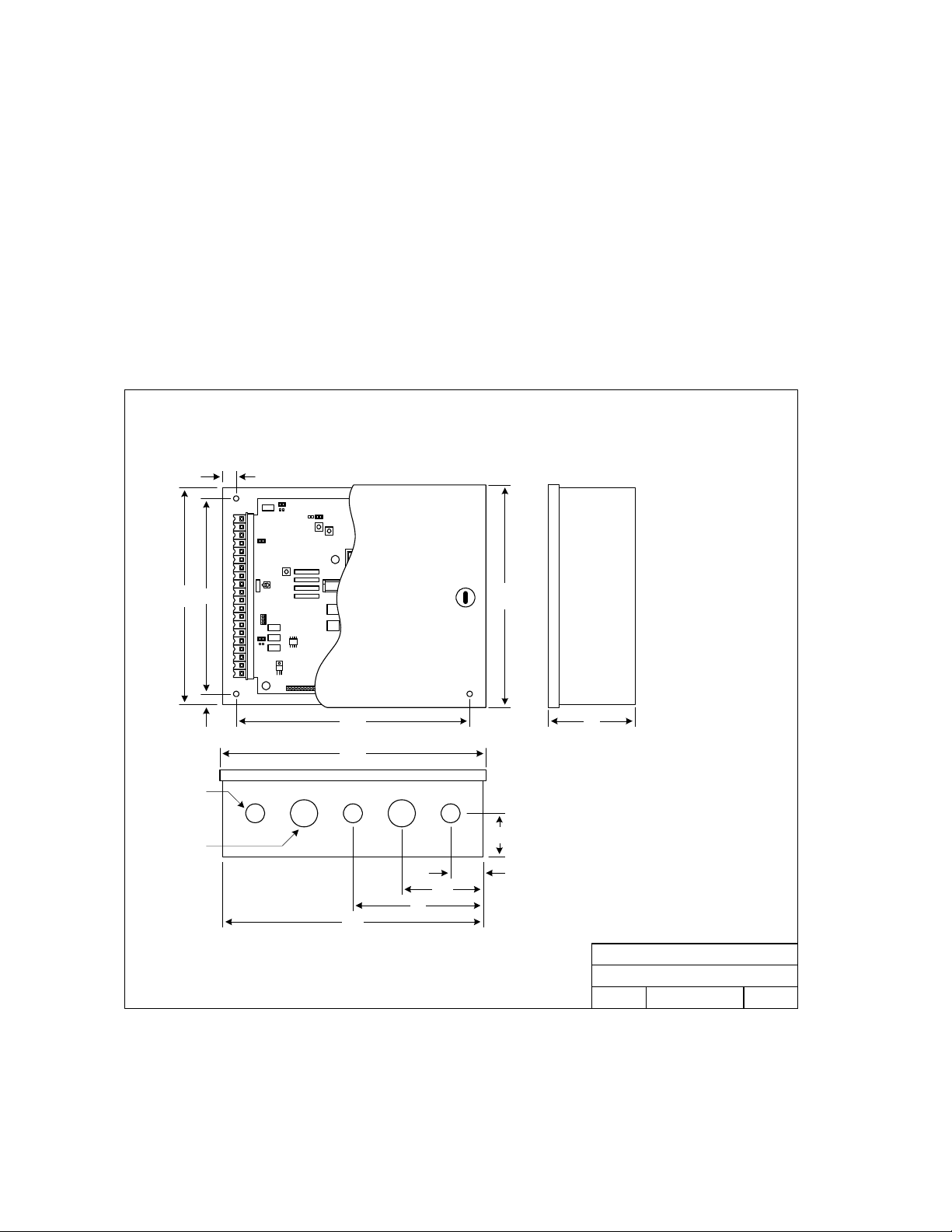
1.1.1 Mount Information
If used to control a door or pedestrian gate, try to locate the access controller as near as possible to
the entry point. The unit should be mounted on a rigid wall to prevent excessive shock and vibration
from closing doors or gates. Continuous vibration and shock from slamming doors or spring-loaded
pedestrian gates will damage the circuit board. Under no circumstances should the unit be
mounted directly to a moving door or gate.
text
10.75
12.25
9.0
10.0
.5
.625
10.25
4.0
3.75
6.0
12.0
2.0
1.5
.875 KO
3-Places
1.125 KO
2-Places
Model 1838 Controller Mounting Dimensions
DOORKING, INC., INGLEWOOD, CA 90301
Title:
Date: Rev.Dwg. No.
B
7/03 M1838-065-1
Page 10 1838-065-U-4-13
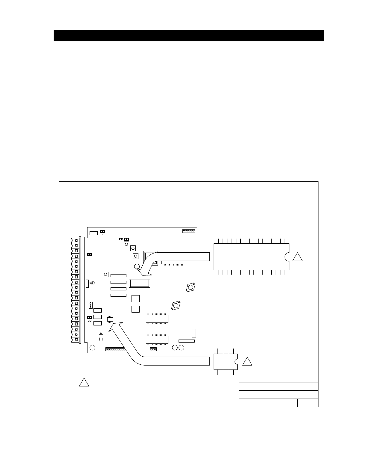
1.2 Memory Chip Information
The 18
38 is shipped with memory chips pre-installed. Do not remove or re-install the memory
chips with power to the system turned on. Doing this will irrevocably damage the memory
chips. Memory chips are static sensitive. Discharge any static electricity from your hands by
touching a proper ground device before removing the control board or memory chips. Handle
memory chips with care.
1. The large memory chip socket is colored black and is located in the center of the circuit
board. Be sure that the handle is in the un-locked position (pointing up). Be sure that
power to the telephone entry system is off.
2. Carefully insert the memory chip into the socket. The small half circular indentation on
the chip must be to the right. CAUTION: Installing the memory chip backwards will
cause permanent damage to the chip. Be sure that the memory chip is seated correctly
in the socket, then move the lever to the locked position.
3. Install the small memory chip in the socket located at the bottom of the circuit board. The
small circular indentation on the chip must be to the right. CAUTION: Installing the
memory chip backwards will cause permanent damage to the chip. Be sure that the
memory chip is seated correctly in the socket .
1838 Series Circuit Boards Memory Chip Location
1
1
Dimple on chip must be towards the right!
1
DOORKING, INC., INGLEWOOD, CA 90301
Date: Dwg. No.
1838 Series Memory Chip Location
Rev.
Title:
4/03
A
M1838-065-2
1838-065
-U-4-13 Page
11

Page 12 1838-065-U-4-13

SECTION 2 – WIRING
Prior to installing wiring to the access control system, we suggest that you become familiar with the
instructions, illustrations, and wiring guidelines in this manual. This will help insure that you
installation is performed in an efficient and professional manner.
The wiring of the access control panel is an extremely important and integral part of the
overall access control system. Use proper wire for the communication line, power wires, and
be sure that the system is properly grounded. Check all local building ordinances and
building codes prior to installing this system. Be sure your installation is in compliance with
local codes.
WARNING: If this access control system is used to control a vehicular gate with an automatic
gate operator, the access devices (card reader, keypad, etc.) must be mounted a minimum of
ten (10) feet away from the gate and gate operator, or in such a way that the user cannot come
into contact with the gate or gate operator when using the entry device. If the entry device
has been installed closer to the automated vehicular gate, do not proceed with any wiring until
the device has been moved and re-installed so that it is in compliance with these instructions.
Use only the supplied transformers (or U.L. listed equivalent) to power the access control system and
any wiegand input devices (16.5 VAC, 20 VA). Do not power any other devices (electric strikes,
magnetic locks, etc.) from these power transformers. For wire runs up to 100 feet, use 18 AWG, 600
volt insulated wire. For wire runs up to 200 feet, use 16 AWG, 600 volt insulated wire. Power wires
are susceptible to noise and hum pickup; therefore it is preferable that you keep power wire runs as
short as possible.
This access control system contains a number of static sensitive components that can be damaged or
destroyed by static discharges during installation or use. Discharge any static prior to removing the
circuit board from the lobby panel by touching a proper ground device.
If Tracker expansion boards are being used with this system, refer to the Tracker Installation and
Wiring manual that came with the Tracker expansion boards, for detailed information on wiring
Tracker boards to the PC programmable access control system.
If Elevator Control is used with this system, refer to the Elevator Control Installation and Wiring
manual for detailed information on wiring the elevator control boards to this system and to the
elevator push button control panel.
.
1838-065
-U-4-13 Page
13
2.1 WIRING GUIDELINES
Do not run hi
gh voltage (115 V) power lines and communication lines in the same conduit. These
should be in separate conduits at least six (6) inches apart. Be sure that all phone line wiring is
twisted and completely isolated from ground.
Use only the supplied 16.5 VAC (or U.L. listed equivalent) to power the access control system. Do
not power any other devices (electric strikes, magnetic locks, lights, etc.) from this
transformer. Do not run 16 VAC access control system power lines over 200 feet. It is advisable to
keep these wires as short as possible. Use 18 AWG wire for wire runs up to 100 feet, and 16
AWG wire for wire runs up to 200 feet. Install a low voltage surge suppresser (DoorKing p/n 1878-
010 or equivalent) to help protect the entry system from power surges.
Wiegand wire runs are 500-feet maximum. Use 6-conductor stranded wire with overall shield. 18,
20, 22 or 24 gauge is sufficient for these connections.
A 12 volt .8 amp hour gel-cell battery (DoorKing p/n 1801-008) can be installed in the system to
provide stand-by power in the event of a power outage. Two batteries are required, one for the
system power and one for the auxiliary terminal power.
Proper grounding of this system is a requirement. The use of surge suppressers can significantly
reduce the chance of component failure because of static charges or surges. To be effective, ground
connections should be made with a minimum 12 AWG, 600 volt insulated wire to a ground point
within 10 feet of the access control system. The ground point must be at an electrical panel, a
metallic cold water pipe that runs in the earth, or a stainless steel grounding rod driven at least ten
(10) feet into the soil.
Be sure that you use proper wire that has an insulation rated for an underground environment. All
wires should be placed in conduits. Proper pre-planning can greatly ease the installation and wiring
of this system. Always check with the local building code to determine the type of wire required in
your municipality.
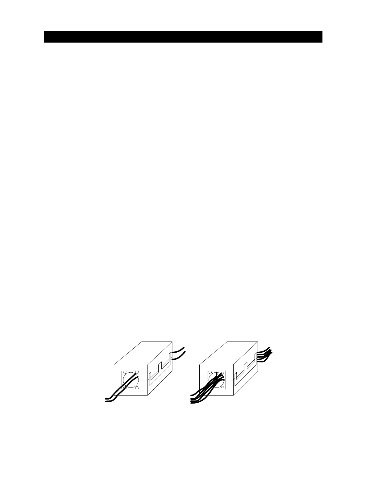
The 1838 is shipped with two (2) Ferrite Filters. One is installed on the 16 VAC power wires to the
main circuit board (terminals 19-20). The second is installed and around the wires connected to the
Auxiliary Terminal strip.
To install the ferrite filter, simply snap the filter open, place the wires in the circular core, then
snap the filter closed.
16 VAC POWER AUX TERMINAL WIRES
Page 14 1838-065-U-4-13

MAIN DESCRIPTION
1 Phone Line Connection – 800 ft. maximum with 24 AWG wire; 1600 ft. maximum with 22 AWG wire.
2 Phone Line Connection – 800 ft. maximum with 24 AWG wire; 1600 ft. maximum with 22 AWG wire.
3 Earth Ground Only.
4 Switch Input. A closure between terminals 4 and 6 will cause the designated relay(s) to activate for the
programmed strike time. The Postal Switch is connected here.
5 Microphone Input.
6 Common for switch input, A and Z input, speaker, microphone and battery negative.
7 Speaker Output.
8 Not Used.
9 Not Used.
10 Not Used.
11 Z Input. A closure between terminals 11 and 6 will dial the phone number stored under directory code 1,
01, 001 or 0001.
12 A Input. A closure between terminals 12 and 6 will dial the phone number stored under directory code 0,
00, 000 or 0000.
13 Relay 2 Common – 30 Volt, 3 Amp maximum.
14 Relay 2 Contact – 30 Volt, 3 Amp maximum.
15 Relay 1 Common – 30 Volt, 3 Amp maximum.
16 Relay 1 Normally Closed – 30 Volt, 3 Amp maximum.
17 Relay 1 Normally Open – 30 Volt, 3 Amp maximum.
18 Microphone Power and Back-up Battery POSITIVE (connect negative to terminal 6).
19 16 VAC Input Power – 20 VA minimum.
100 ft. maximum with 18 AWG wire; 200 ft. maximum with 16 AWG wire.
20 16 VAC Input Power – 20 VA minimum.
100 ft. maximum with 18 AWG wire; 200 ft. maximum with 16 AWG wire.
AUXILIARY DESCRIPTION
1 16 VAC Input Power – 20 VA.
2 16 VAC Input Power – 20 VA.
3 Back-up Battery POSITIVE.
4 Back-up Battery NEGATIVE.
5 16 VAC for Card Reader lights only.
6 16 VAC for Card Reader lights only.
7 DATA 0 – Card Reader 2.
8 DATA 1 – Card Reader 2.
9 COMMON – Card Reader 2.
10 +12 VDC Power – Card Reader 2.
11 DATA 0 – Card Reader 1.
12 DATA 1 – Card Reader 1.
13 COMMON – Card Reader 1.
14 +12 VDC Power – Card Reader 1.
ELEVATOR DESCRIPTION
1 DATA 1 – connect to Elevator Control Board (2348-010) Terminal 20.
2 DATA 0 – connect to Elevator Control Board (2348-010) Terminal 21.
3 COMMON – connect to Elevator Control Board (2348-010) Terminal 22.
2.2 TERMINAL DESCRIPTIONS
1838-065
-U-4-13 Page
15
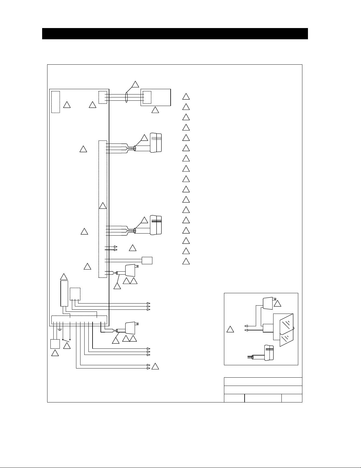
2.3 WIRING DETAIL
2.3.1 Controller Only
C.O.
PHN
Elevator
Control
RS 232
Connection
Auxiliary Terminals
Main Terminal
Relay 0
4 5
1833, 1834, 1835, 1837, 1838 CONTROLLER
30 Series Controller Detail Wiring
NOTES: Relay 0 is not available on the 1834 controller.
1
2
3
4
5
6
1
2
3
123 1716151413 2019
NO
NC
COM
14
13
12
11
10
9
8
7
6
5
4
3
2
1
94
NEG 12 VDC INPUT
POS 12 VDC INPUT
16 VAC
OUTPUT
3
46 18
- 12 VDC BATT INPUT
+12 VDC BATT INPUT
1
2
3
7
DOORKING, INC., INGLEWOOD, CA 90301
Date: Dwg. No. Rev.
Title:
7/12
E
M1835-065-2
Detail Wiring - 30 Series Controller
RELAY 1 NORMALLY OPEN
RELAY 1 NORMALLY CLOSED
RELAY 1 COMMON
RELAY 2 CONTACT
RELAY 2 COMMON
RED
BLK
WHT
GRN
+ 12 VDC
COMMON
DATA 1
DATA 0
CARD
RDR-1
RED
BLK
WHT
GRN
+ 12 VDC
COMMON
DATA 1
DATA 0
ELEVATOR
CONTROL
2348-010
WHT
GRN
BLK
DATA 1
DATA 0
COMMON
20
21
22
7
8
6
16 Volt, 20 VA UL Listed Transformer.
Battery Backup - separate batteries required for phone
system and weigand terminals.
1
Central Office phone line - touch tone, loop start.
2
A switch closure across terminals 4 & 6 will activate relay 1
for its programmed strike time.
3
4
5
6
For 1837, use 16 Volt, 40 VA UL Listed Transformer.
6 conductor, stranded with overall shield, 18, 20, 22 or 24
gauge is sufficient for these connections.
See Dwg No. M1835-065-5 for detail.
8
See Elevator Control Board Manual 2348-065 for detail.
9
Aux power transformer must be connected. Otherwise, RS232,
elevator control and weigand inputs will not function.
10
10
16 VAC output can be used to power lights on card readers that
have additional lighting for outdoor use.
11
12
12
11
Card reader connected to these terminals will operate Relay 1
for its programmed strike time.
Card reader connected to these terminals will operate Relay 2
for its programmed strike time.
13
13
Relay 2 contact is set N.O or N.C. with a jumper on the circuit
board.
14
Electric strikes are wired to Normally Open (N.O.) contacts;
magnetic locks are wired to the Normally Closed (N.C.) contacts.
15
Power for electric strikes or magnetic locks is not provided by the
system. Use a separate UL listed power supply.
16
16
16
Auxiliary and Elevator Control terminals are not available on the
1834 controller.
6
6
CARD
RDR-2
BLK
RED
12 VDC
BATT
17
17
17
Use 18 AWG wire for runs up to 100 Ft. Use 16 AWG wire for
runs up to 200 Ft.
DOOR
LOCK
To Control
Relay
14
15
BASIC DOOR CONTROL
CARD
READER
To Card
Reader Input
16 VAC
PWR
INPUT
16 VAC
PWR
INPUT
LOCK
PWR
RELAY 0 COMMON
RELAY 0 NORMALLY CLOSED
RELAY 0 NORMALLY OPEN
Page 16 1838-065-U-4-13
Loading...