

Page 1
PLASTIC FOLDING ARM KIT
Installation
DoorKing Part Number
1601-083
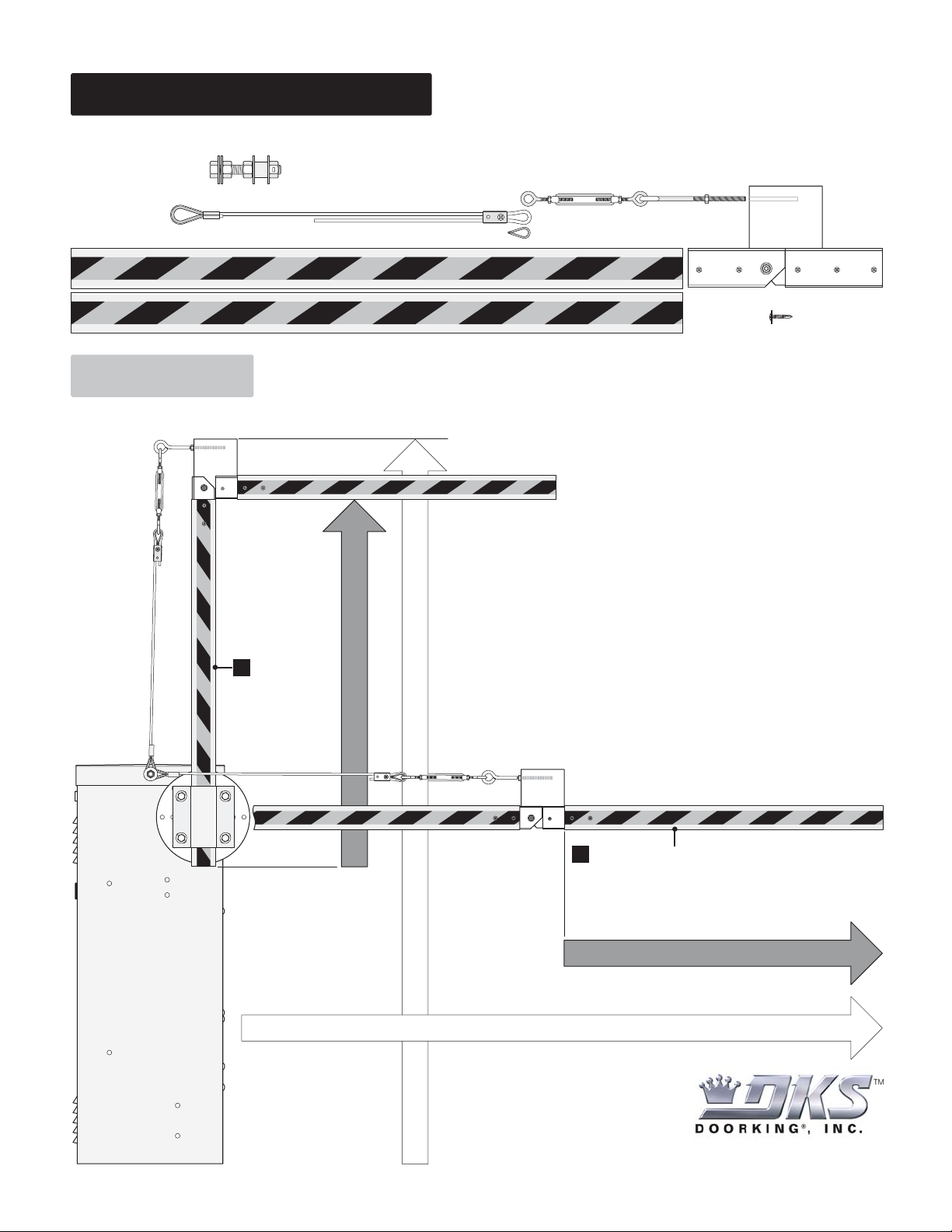
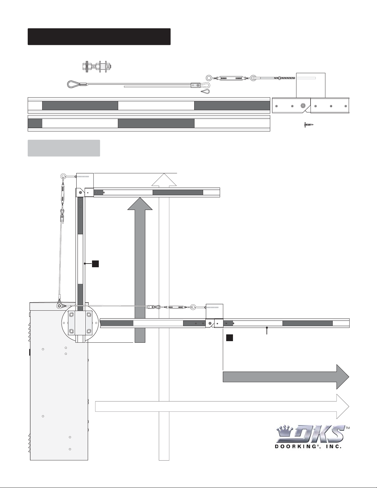
This kit is designed for the 1600 model barrier gate operators only. Recommended for low headroom applications.
Kit Includes:
Cut this arm
first for the
height
limitations.
Determining First Arm Length
Cut this arm second for the
traffic lane width.
Note: Second arm can be a
different size than the first.
Determining Second Arm Length
Cut Arms to Length
Traffic Lane Width
Total Height
Pre-Crimped Eyelet
Cable Attachment Assembly
Cable
2 Plastic Arms
(Connected)
Arm Hinge
8 Self Tapping Screws
Cable
Clamp
Cable Eyelet
Locking Eye BoltLocking Turnbuckle
Note: Completed folding arm
assembly shown in the UP position
to illustrate the total height.
Note: Completed folding arm assembly
shown in the DOWN position to illustrate
traffic lane width.
1
2
120 Glasgow Avenue
Inglewood, California 90301 U.S.A.
Page 2
1601-083-C-5-08
DoorKing Part Number
1601-083
Copyright 2008 DoorKing, Inc. All rights reserved.
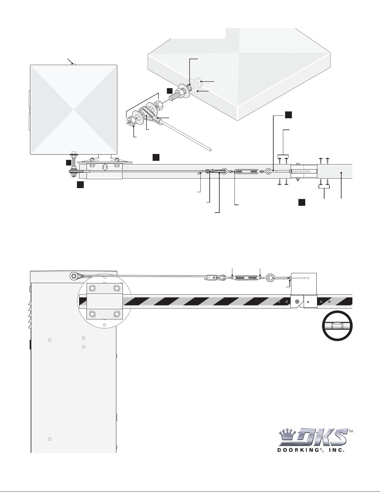
Top View of
Operator Housing
Side View of
Operator Housing
120 Glasgow Avenue
Inglewood, California 90301
U.S.A.
Hub
Existing Stud
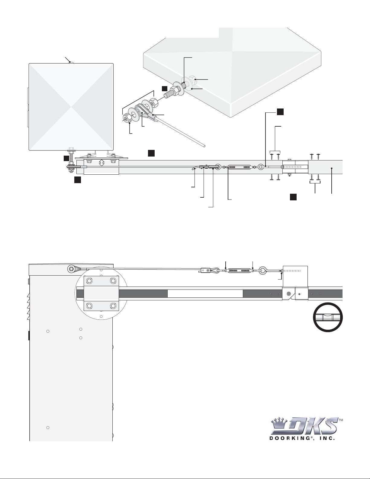
Important: Do not adjust cable too tight or it will bind.
Adjusting and Locking Cable Assembly
After adjusting cable tension, lock turnbuckle
with nuts to keep turnbuckle from twisting.
Rotate arm up and down. Adjust cable tension with turnbuckle
to level outer arm. Make sure that cable assembly is not binding
or twisting and everything moves freely.
Lock eye bolt with nut to keep eye bolt from twisting.
Inner Arm
Outer Arm
Cable Eyelet MUST be installed in turnbuckle.
Cable Clamp
Install eye bolt into arm
hinge with vise-grips.
Attach arm hinge to
inner arm with 4
self-tapping screws.
1
2
3A
3A
Allow turnbuckle to
loosen or tighten.
Install inner arm
on hub.
3
4
Install cable. Cable MUST clear hub!
Cut off excess cable.
Remove stud from operator housing
and assemble as shown.
Bushing
Operator Housing
Adjust to clear hub.
Pre-Crimped Eyelet
Bolt Head (Inside Housing)
Washer (Inside Housing)
Locknut
Install outer arm
with 4 self-tapping
screws.
Installing Arms
Page 3

Note: Completed folding arm
assembly shown in the UP position
to illustrate the total height.
WOOD FOLDING ARM KIT
Installation
DoorKing Part Number
1601-084
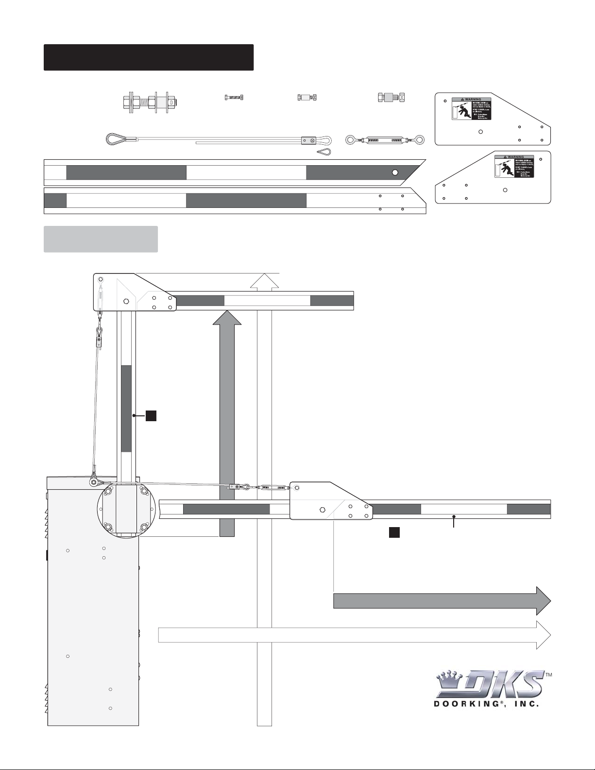
This kit is designed for the 1600 model barrier gate operators only. Recommended for low headroom applications.
Kit Includes:
Cut this arm
first for the
height
limitations.
Determining First Arm Length
Cut this arm second for the
traffic lane width.
Note: Second arm can be a
different size than the first.
Determining Second Arm Length
Cut Arms to Length
Traffic Lane Width
Total Height
Pre-Crimped Eyelet
Cable Attachment Assembly
Cable
2 Wood Arms
Cable Clamp
2 Hinge Plates
Cable Eyelet
Locking Turnbuckle
Note: Completed folding arm assembly
shown in the DOWN position to illustrate
traffic lane width.
1
2
120 Glasgow Avenue
Inglewood, California 90301 U.S.A.
4 Bolts with
Locknuts (Small)
Bolt with Bushing
and Locknut (Medium)
Bolt with Brass Bushing
and Locknut (Large)
MOVING ARM
can
cause vehicle damage,
serious injury or death.
STAY CLEAR
of arm
at all times.
NO:
Pedestrians
Bicycles
Motorcycles
WARNING
MOVING ARM
can
cause vehicle damage,
serious injury or death.
STAY CLEAR
of arm
at all times.
NO:
Pedestrians
Bicycles
Motorcycles
WARNING
Page 4
1601-084-D-5-08
DoorKing Part Number
1601-084
Copyright 2008 DoorKing, Inc. All rights reserved.
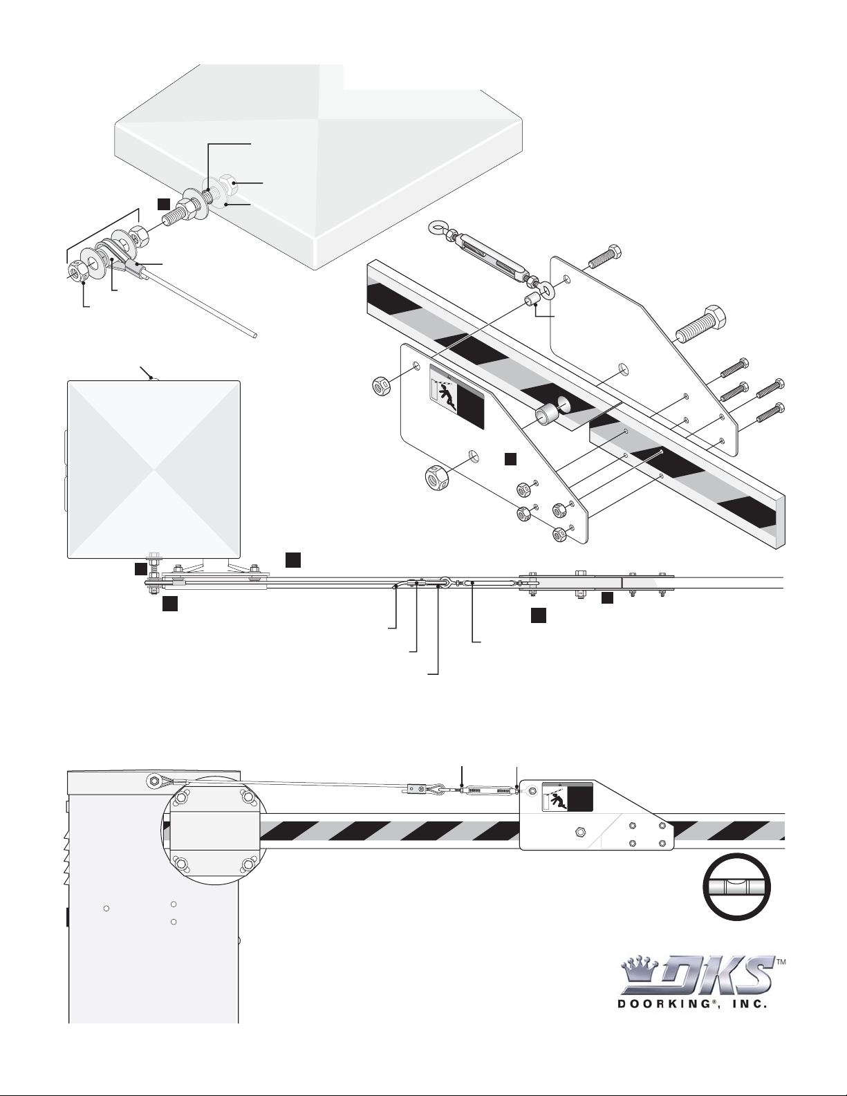
Top View of
Operator Housing
120 Glasgow Avenue
Inglewood, California 90301
U.S.A.
Hub
Existing Stud
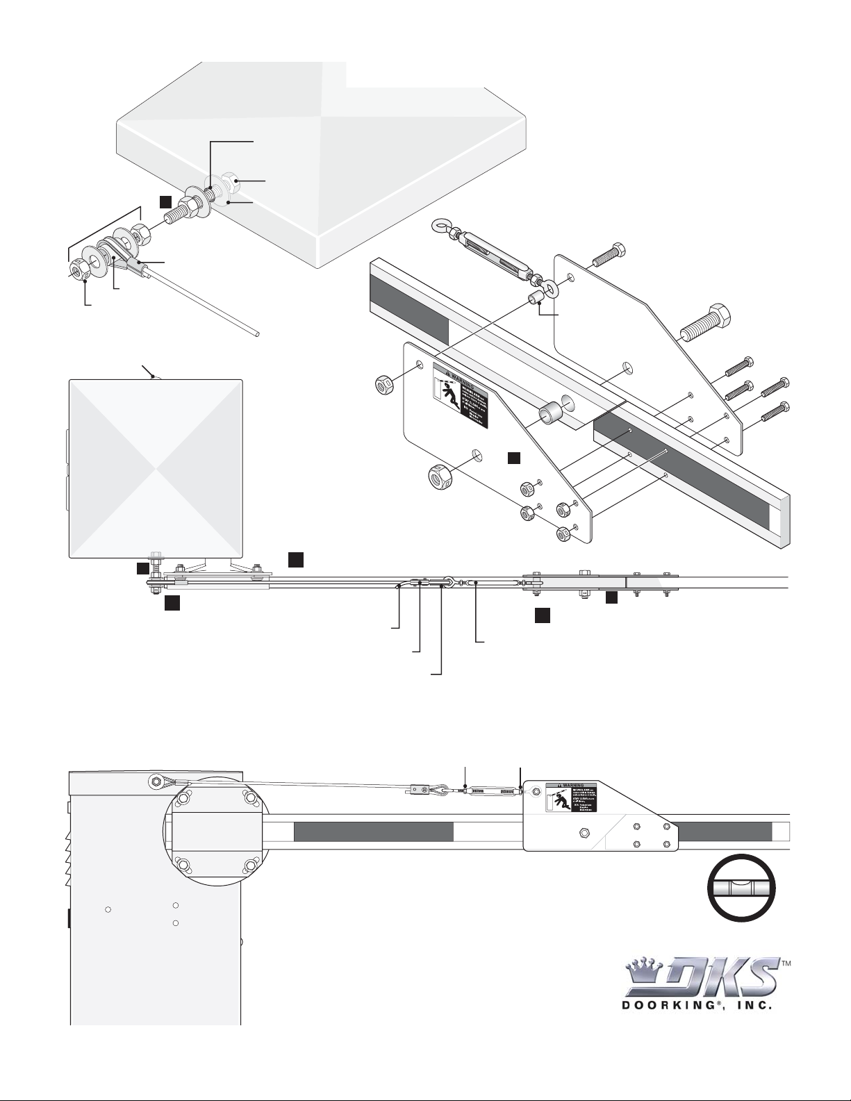
Important: Do not adjust cable too tight or it will bind.
Adjusting and Locking Cable Assembly
After adjusting cable tension, lock turnbuckle with nuts in position shown to prevent
turnbuckle from rubbing against hinge plates when the arm is in the UP position.
Rotate arm up and down. Adjust cable tension with turnbuckle
to level outer arm. Make sure that cable assembly is not binding
or twisting and everything moves freely.
Inner Arm
Outer Arm
Outer Arm
1
3A
2A
3A
Install inner arm on hub.
2
Install hinge plates.
3
Install cable. Cable MUST clear hub!
Remove stud from operator housing
and assemble as shown.
Bushing
Operator Housing
Adjust to clear hub.
Pre-Crimped Eyelet
Bolt Head (Inside Housing)
Washer (Inside Housing)
Locknut
Installing Arms
Installing Cable
Attachment Assembly
Side View of
Operator Housing
MOVING ARM
can
cause vehicle damage,
serious injury or death.
STAY CLEAR
of arm
at all times.
NO:
Pedestrians
Bicycles
Motorcycles
WARNING
Cable Eyelet MUST be installed in turnbuckle.
Cable Clamp
Allow turnbuckle to
loosen or tighten.
Cut off excess cable.
Bushing
Turnbuckle
Bolt (Medium)
Bolt (Large)
4 Bolts (Small)
Brass
Bushing
Installing Hinge Plates
M
O
V
ING
A
R
M
ca
n
cau
se
ve
hi
c
le
d
a
m
a
ge
,
se
r
io
us in
j
u
r
y o
r
d
e
a
t
h.
S
T
A
Y
C
L
E
A
R
o
f
a
r
m
a
t
all
time
s
.
N
O
:
P
ed
es
t
r
ia
n
s
B
i
c
y
cl
e
s
M
ot
or
c
y
cl
e
s
WAR
NING
Locknut
Locknut
4 Locknuts
2A
O
u
ter A
rm
Inner Arm
Page 5
DoorKing Part Number
MODEL 1601 FAN KIT
1601-093
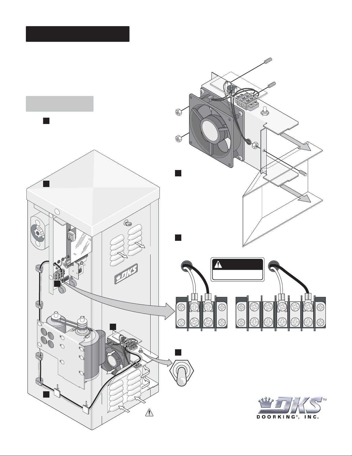
This kit is designed for the 1600 model barrier gate operators only. Recommended for hot and humid climates. An automatic
thermostat will control heat and humidity inside operator housing.
Kit Includes: Fan Assembly with black and white wires, 5 wire ties,
3 double stick wire tie mounts, 2 plastic wire restrainers and 3 nylon
lock nuts.
Installation
1
Shut off ALL power to operator
Turn off the DC convenience open power switch
on certain operator models FIRST then shut off
the AC input power to the operator from the
circuit breaker.
Route fan wires as shown. Use supplied
3
wire stays and existing wire restrainers.
Keep wires clear of all moving parts.
Lock Nut
Lock Nut
2
Mount fan using 3 existing
threaded studs and lock
nuts supplied. Slide
mounting tabs over
existing air duct.
Housing Studs
Lock
Nut
Threaded
(Existing)
Mounting
Tab
Mounting
Tab
Existing
Air Duct
Threaded
Air Duct
Stud
(Existing)
4
Existing Wire Restrainers
3
1601-093-B-5-11
Wire Stays
Existin
Air Duct
Connect the fan power
4
wires according to
operator model type.
Exhaust Vents
Neutral
DANGER
HIGH VOLTAGE!
Hot
Neutral
Neutral
1212 345
115 VAC Hot
2
115 VAC Models 230 VAC/460 VAC Models
Fan switch settings.
5
OFF - Turns the fan off.
Air
Flow
g
Keep intake vents clear of debris.
Intake Vents
Copyright 2011 DoorKing, Inc. All rights reserved.
ON - Turns the fan on continuously.
AUTO - Normal setting. Automatically turns the fan ON when the
temperature rises above 90°F inside the housing, and turns the fan OFF
when the temperature drops below 90°F.
120 Glasgow Avenue
Inglewood, California 90301
U.S.A.
Page 6
DoorKing Part Number
1600 115 VAC - 3.3 AMP HEATER KIT
1601-092
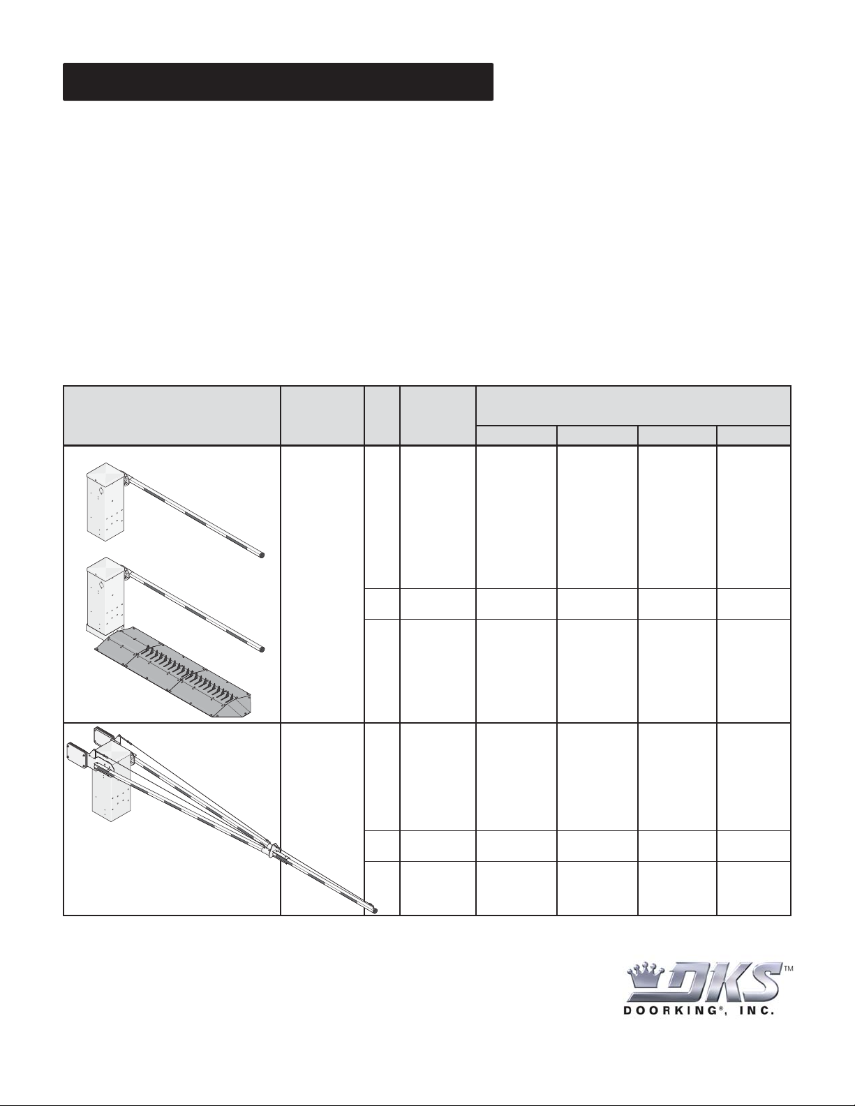
This kit is designed for the 1600 model barrier gate operators only. For cold weather climates where temperatures routinely drop
below 40°F (4°C). A built-in thermostat will automatically control the temperature inside operator housing.
High Voltage AC Input Power for the 1600 Barrier Gate Operator with a Heater
DO NOT use the “high voltage wire size and distance requirements” table in the Installation/Owner’s manuals to determine the high
voltage AC input power wire size and distance requirements for the barrier gate operator because of a much greater current draw
when using the heater. Use the table below to determine the wire size and distances for your chosen barrier gate operator when a
heater is installed. EACH operator should have a “Dedicated” circuit breaker at the power source.
If the high voltage AC input power wiring is greater than the maximum distance shown, it is recommended that a service feeder be
installed. When large gauge wire is used, a separate junction box must be installed for the operator connection. Wire run distances
are based on NEC guidelines for copper wire allowing a maximum 3% voltage drop on the line. The calculated distance was then
further reduced by 10% to allow for other loses in the system. Never run low voltage rated wire insulation in the same conduit as
high voltage rated wire insulation.
High voltage AC input wire size and distance requirements for a 1600 with a heater.
Operator
and
Heater
Model Horsepower Volts 12 AWG 10 AWG 8 AWG 6 AWG
Amps
Wire Size / Distance in Feet
1601
1603
1602
1/2 HP
1 HP
115
230
460
115
230
460
9.0
4.6
2.4
13.0
6.5
3.3
105
420
1615
70
295
1175
175
675
2585
120
475
1880
290
1125
4310
200
795
3136
435
1685
6465
300
1190
4705
In bi-parting (dual) barrier gate applications, high voltage AC input power
is required for EACH 1600 operator with heater.
120 Glasgow Avenue
Inglewood, California 90301
U.S.A.
Page 7
DoorKing Part Number
Installation of Heater
1601-092
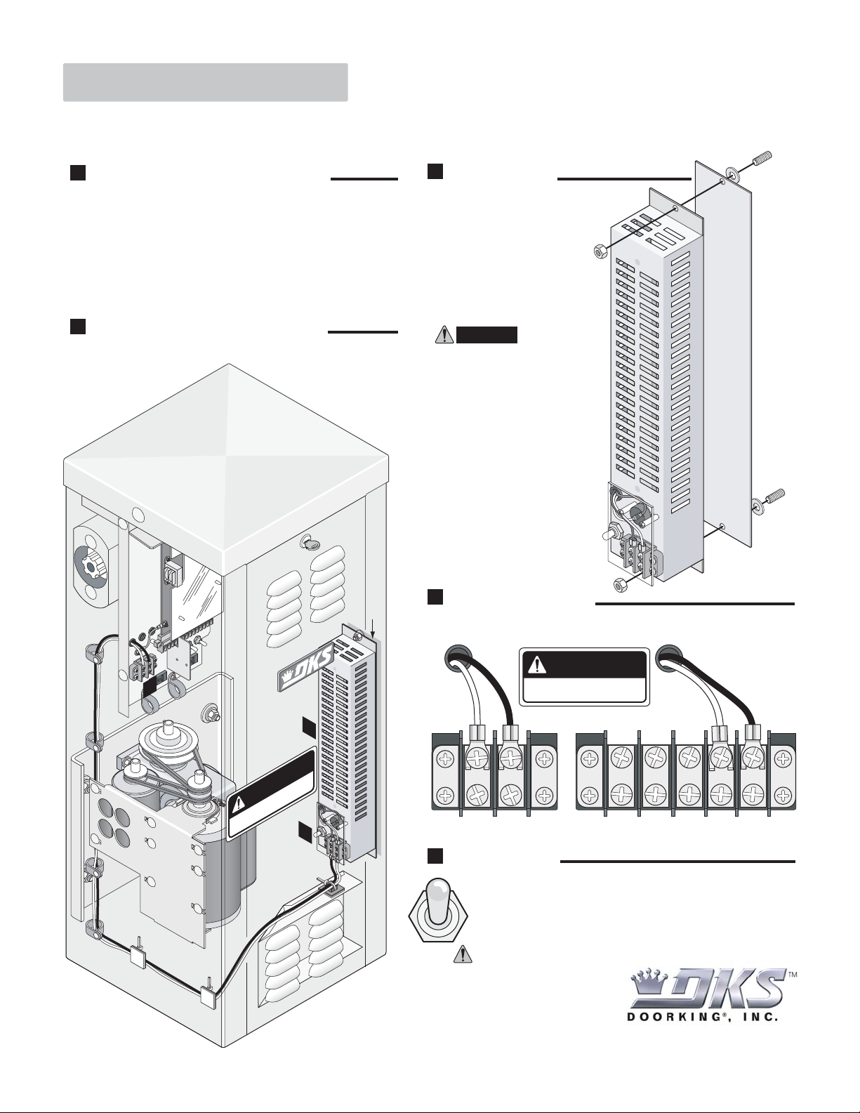
Kit Includes: Heater / mounting plate, 2 locknuts, 5 wire ties, 3 double stick wire tie mounts, and 2 plastic wire restrainers.
1
Shut off ALL power to operator.
Turn off the DC convenience open power switch on
certain operator models first then shut off the AC input
power to the operator from the circuit breaker.
3
Route heater wires as shown.
Use supplied wire stays and existing wire
restrainers.
Keep wires clear of all moving parts
and the heater vents.
2
Mount Heater
Locate existing threaded studs in
operator. Heater MUST be
mounted on mounting plate.
Place the 2 supplied
washers between the
operator wall and
the mounting plate to create
an air gap.
CAUTION: Heat will be
transferred to the outside
wall of the operator if NO
air gap exists between the
heater and the inside wall
of the operator.
Locknut
Washer
Mounting
Plate
Operator
Threaded
Stud
(Existing)
Operator
Threaded
Stud
(Existing)
Washer
4
Existing Wire Restrainers
Wire Stays
2
DANGER
HOT!
5
Air Gap
Locknut
4
Power Connection
Connect the heater power wires according to operator
AC power type.
DANGER
HIGH VOLTAGE!
Neutral
115 VAC Models
5
Heater Switch
AUTO - Normal setting. Automatically turns the heater ON when the
temperature drops below 40°F inside the operator, and turns the heater
OFF when the temperature rises above 40°F inside the operator.
OFF - Turns the heater off.
ON - Turns the heater on continuously. The heater will become VERY
HOT when running continuously.
Hot
1
212 345
230 VAC/460 VAC Models
Neutral
115 VAC Hot
1601-164-G-7-11
Copyright 2011 DoorKing, Inc. All rights reserved.
120 Glasgow Avenue
Inglewood, California 90301 U.S.A.
Page 8
ALUMINUM ARM FOLDING KIT
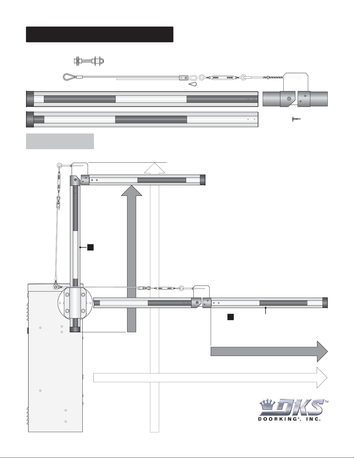
This kit is designed for the 1600 model barrier gate operators only. Recommended for low headroom applications.
DoorKing Part Number
1601-310
Kit Includes:
Cable Attachment Assembly
Pre-Crimped Eyelet
2 Aluminum Arms with End Caps
Installation
Cable
Cable
Clamp
Cable Eyelet
Cut Arms to Length
Locking Eye BoltLocking Turnbuckle
(Connected)
Arm Hinge
8 Self Tapping Screws
Note: Completed folding arm
assembly shown in the UP position
to illustrate the total height.
Cut this arm
1
first for the
height
limitations.
Total Height
Determining First Arm Length
Note: Completed folding arm assembly
shown in the DOWN position to illustrate
traffic lane width.
Cut this arm second for the
2
traffic lane width.
Note: Second arm can be a
different length than the first.
Determining Second Arm Length
Traffic Lane Width
120 Glasgow Avenue
Inglewood, California 90301
U.S.A.
Page 9
Installing Arms
DoorKing Part Number
1601-310
Existing Stud
Top View of
Operator Housing
3A
1
Hub
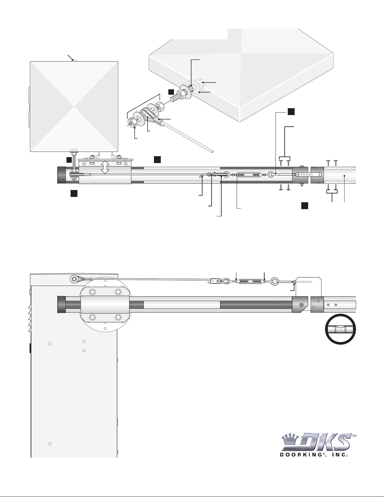
Install arm on hub.
Cable Eyelet MUST be installed in turnbuckle.
Adjust to clear hub.
Bushing
Locknut
3
Cut off excess cable.
Remove stud from operator housing
and assemble as shown.
Bolt Head (Inside Housing)
3A
Washer (Inside Housing)
Operator Housing
Pre-Crimped Eyelet
Install cable. Cable MUST clear hub!
Cable Clamp
Allow turnbuckle to
loosen or tighten.
Install eye bolt into arm
2
hinge with vise-grips.
Attach arm hinge to arm
with 4 self-tapping
screws.
Install second arm
4
with 4 self-tapping
screws.
Side View of
Operator Housing
Adjusting and Locking Cable Assembly
After adjusting cable tension, lock turnbuckle
with nuts to keep turnbuckle from twisting.
Lock eye bolt with nut to keep eye bolt from twisting.
Inner Arm
Rotate arm up and down. Adjust cable tension with turnbuckle
to level outer arm. Make sure that cable assembly is not binding
or twisting and everything moves freely.
Important: Do not adjust cable too tight or it will bind.
Outer Arm
1601-265-C-6-11
Copyright 2011 DoorKing, Inc. All rights reserved.
120 Glasgow Avenue
Inglewood, California 90301
U.S.A.
Page 10
PLASTIC FOLDING ARM KIT
This kit is designed for the 1600 model barrier gate operators only. Recommended for low headroom applications.
Kit Includes:
Locking Eye BoltLocking Turnbuckle
(Connected)
Arm Hinge
8 Self Tapping Screws
Pre-Crimped Eyelet
2 Plastic Arms
Cable Attachment Assembly
Cable
Cable
Clamp
Cable Eyelet
Installation
Cut Arms to Length
Note: Completed folding arm
assembly shown in the UP position
to illustrate the total height.
DoorKing Part Number
1601-083
Cut this arm
1
first for the
height
limitations.
Total Height
Determining First Arm Length
Note: Completed folding arm assembly
shown in the DOWN position to illustrate
traffic lane width.
Cut this arm second for the
2
traffic lane width.
Note: Second arm can be a
different size than the first.
Determining Second Arm Length
Traffic Lane Width
120 Glasgow Avenue
Inglewood, California 90301
U.S.A.
Page 11
Installing Arms
DoorKing Part Number
1601-083
Existing Stud
Top View of
Operator Housing
3A
Hub
Install inner arm
1
on hub.
Cable Eyelet MUST be installed in turnbuckle.
Adjust to clear hub.
Bushing
Locknut
3
Cut off excess cable.
Remove stud from operator housing
and assemble as shown.
Bolt Head (Inside Housing)
3A
Washer (Inside Housing)
Operator Housing
Pre-Crimped Eyelet
Install cable. Cable MUST clear hub!
Cable Clamp
Allow turnbuckle to
loosen or tighten.
Install eye bolt into arm
2
hinge with vise-grips.
Attach arm hinge to
inner arm with 4
self-tapping screws.
Install outer arm
4
with 4 self-tapping
screws.
Side View of
Operator Housing
Adjusting and Locking Cable Assembly
After adjusting cable tension, lock turnbuckle
with nuts to keep turnbuckle from twisting.
Lock eye bolt with nut to keep eye bolt from twisting.
Inner Arm
Rotate arm up and down. Adjust cable tension with turnbuckle
to level outer arm. Make sure that cable assembly is not binding
or twisting and everything moves freely.
Important: Do not adjust cable too tight or it will bind.
Outer Arm
1601-266-B-6-11
Copyright 2011 DoorKing, Inc. All rights reserved.
120 Glasgow Avenue
Inglewood, California 90301
U.S.A.
Page 12
WOOD FOLDING ARM KIT
This kit is designed for the 1600 model barrier gate operators only. Recommended for low headroom applications.
Kit Includes:
Pre-Crimped Eyelet
2 Wood Arms
Cable Attachment Assembly
4 Bolts with
Locknuts (Small)
Cable
Bolt with Bushing
and Locknut (Medium)
Cable Clamp
Cable Eyelet
Bolt with Brass Bushing
and Locknut (Large)
Locking Turnbuckle
Installation
Cut Arms to Length
Note: Completed folding arm
assembly shown in the UP position
to illustrate the total height.
DoorKing Part Number
1601-084
2 Hinge Plates
Cut this arm
1
first for the
height
limitations.
Total Height
Determining First Arm Length
Determining Second Arm Length
Note: Completed folding arm assembly
shown in the DOWN position to illustrate
traffic lane width.
Cut this arm second for the
2
traffic lane width.
Note: Second arm can be a
different size than the first.
Traffic Lane Width
120 Glasgow Avenue
Inglewood, California 90301
U.S.A.
Page 13
Installing Cable
Attachment Assembly
3A
Adjust to clear hub.
Pre-Crimped Eyelet
Bushing
Locknut
Existing Stud
Top View of
Operator Housing
Installing Arms
Remove stud from operator housing
and assemble as shown.
Bolt Head (Inside Housing)
Washer (Inside Housing)
Operator Housing
Inner Arm
Locknut
Locknut
DoorKing Part Number
1601-084
Installing Hinge Plates
Bolt (Medium)
Turnbuckle
Bolt (Large)
Bushing
4 Bolts (Small)
Brass
Bushing
2A
Outer Arm
3A
Install cable. Cable MUST clear hub!
Hub
Install inner arm on hub.
1
3
Cut off excess cable.
Cable Clamp
Cable Eyelet MUST be installed in turnbuckle.
Adjusting and Locking Cable Assembly
After adjusting cable tension, lock turnbuckle with nuts in position shown to prevent
turnbuckle from rubbing against hinge plates when the arm is in the UP position.
Inner Arm
Rotate arm up and down. Adjust cable tension with turnbuckle
to level outer arm. Make sure that cable assembly is not binding
or twisting and everything moves freely.
4 Locknuts
Install hinge plates.
2
Allow turnbuckle to
loosen or tighten.
Outer Arm
2A
Outer Arm
Side View of
Operator Housing
1601-267-B-6-11
Important: Do not adjust cable too tight or it will bind.
Copyright 2011 DoorKing, Inc. All rights reserved.
120 Glasgow Avenue
Inglewood, California 90301 U.S.A.
Page 14
DoorKing Part Number
1601 Manual Release Kit
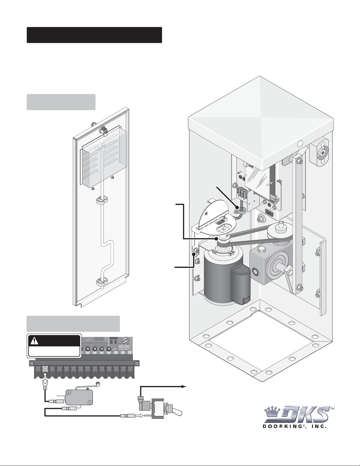
This kit is designed for the 1601 barrier gate operator WITHOUT the convenience open option. It provides an interlock power cut-off
switch when manually using crank tool to move the arm up or down. DO NOT install on convenience open models.
1601-270
Kit Includes: Pre-wired Interlock assembly,
Double motor pulley, Crank tool,
2 spring clips with lock nuts.
Installation
Shut off the AC input
power to the operator
from the circuit
breaker.
Use existing
wire restrainers
to run wires.
Keep wires clear
Mount spring clips
with lock nuts on
existing threaded
studs inside
access door.
Crank Tool
Storage
Replace existing
single motor
pulley with double
motor pulley.
Align motor pulley
with gear reducer
pulley.
Mount interlock
assembly using
existing hardware.
of all moving parts
Interlock Assembly
G
ear
Reducer
Wiring Interlock
DANGER
HIGH VOLTAGE!
1 2 3 4 5 6 7 8 9 10 11 12 13 14
Replace the existing AC power switch wire connected to
terminal #2 with interlock cut-off switch wires.
NC NO
Existing 115 VAC
Power Terminal Wire
Interlock
Cut-Off
Switch
AC Power
Switch
120 Glasgow Avenue
Inglewood, California 90301
U.S.A.
Page 15
Manual Operation
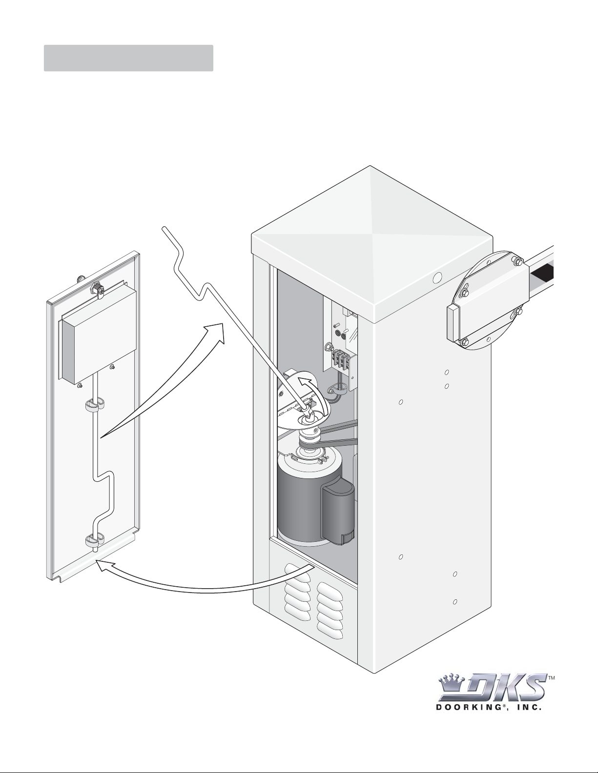
1. Unlock and remove access door.
2. Remove crank tool from inside access door.
3. Flip interlock assembly door up, power will be disabled from operator.
4. Insert crank tool into motor pulley as shown.
5. Rotate crank tool to manually move operator arm up or down.
DoorKing Part Number
1601-270
Access Door
Crank Tool
Storage
Interlock
Assembly
Door
1601-270-C-5-10
Copyright 2010 DoorKing, Inc. All rights reserved.
120 Glasgow Avenue
Inglewood, California 90301
U.S.A.
 Loading...