

DoorKing 6050-080, 6050-081, 6100-080, 6100-081 Installation And Owner's Manual
Installation/Owner’s Manual
Series 6050 and 6100
Series 6050 and 6100
Vehicular Swing Gate Operator
Use this manual for circuit board 4502-010 Revision K or higher.
For operators manufactured January 2016 and later.
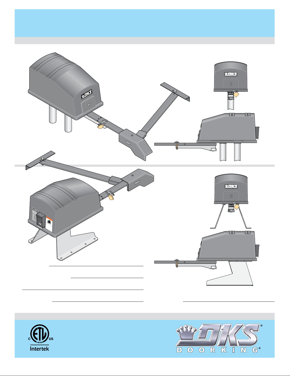
Post Mount
6050-065-C-2-16
EXTERNAL ENTRAPMENT PROTECTION MUST be
installed or the gate operator WILL NOT function.
C
O
N
FO
A
RM
N
S
I/
S
U
T
L
O
-3
C
C
2
A
E
5
N
R
/
T
C
IFIE
S
A
D
C
V
22
TO
E
.
H
2
ICU
N
O
53
.
C
38
LA
2
L
2
47
A
R
S
S
G
A
T
E
M
O
O
D
PE
EL
R
A
T
S
O
E
HP
RIA
R
L
V
OL
T
S
A
M
P
M
A
X
D
WA
S
G
A
T
E
L
O
A
o
orKi
n
g
,
I
n
R
P
N
H
A
S
IN
E
6
D
0
Hz
c
.
,
I
n
g
l
e
woo
d,
C
A
G
M
O
V
S
I
N
ER
G
I
G
OU
A
O
T
S
p
E
e
I
r
N
a
C
a
t
nd
e
JU
A
g
N
f
a
r
t
R
e
e
e
C
Pad Mount
o
Y
of
n
A
l
D
y
O
p
US
o
e
w
R
o
no
h
p
e
D
o
l
E
t
e
n
r
a
a
o
g
l
EA
l
n
p
a
o
d
t
e
w
e
r
o
a
T
a
c
b
t
r
h
e
H
s
e
i
t
D
a
l
g
r
d
a
u
o
i
r
s
t
c
e
e
n
ti
n
i
.
o
n
o
pa
t
t
ns
o
s
s
t
i
g
h
t
pl
.
a
h
n
w
a
t
y
d
hi
i
in
n
l
e
g
g
R
g
a
a
a
e
t
t
t
a
e
e
e
d
a
p
i
s
o
r
a
e
w
t
mo
a
h
n
o
e
v
r
r
i
’
n
s
w
g.
ma
a
l
k
n
th
u
r
a
o
l
u
a
g
nd
h
s
a
f
e
ty
i
n
s
t
r
u
c
t
i
o
n
s
.
Date Installed:
Installer/Company Name:
Phone Number:
Leave Manual with Owner
UL 325 Compliant
Circuit Board
Serial Number
and Revision Letter:
Copyright 2016 DoorKing, Inc. All rights reserved.
Copyright 2009 DoorKing, Inc. All rights reserved.
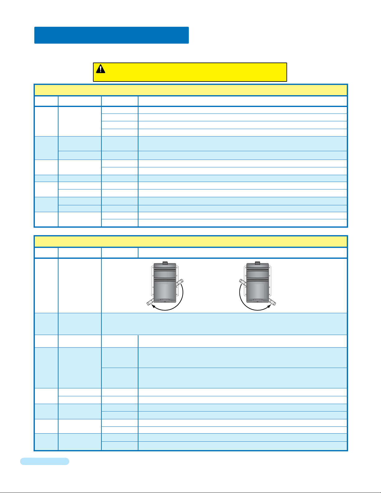
QUICK GUIDE: DIP-Switches
See page 20 for descriptions about DIP-switches.
When a switch setting is changed, power must be turned OFF and then turned back ON for the new setting to take affect.
Every time the operator is powered up, the First open command will
automatically set the open and close limits of the gate. (See page 21).
SW 1 (Top 8 Switches)
Switch Function Setting Description
Relay activates when gate is open (Shadow loop setting when used).
Relay activates when gate is not closed.
2-ON
Relay activates when gate is opening and open.
Relay activates when gate is opening and closing.
2-ON
The output wired to terminal #12 becomes the output from the exit loop detector plugged
OFF
into the EXIT Loop port.
Normal Setting. Terminal #12 is a normal full open input.
ON
Auto-close timer is OFF. Manual input required to close gate.
OFF
Auto-close timer is ON. Adjustable from 1-23 seconds to close gate.
ON
Leave in the OFF position.
OFF
OFF when using a 3-button station (DoorKing 3-button control stations only).
OFF
ON when using a single button control,
ON
Switch must be OFF when bi-parting (dual) gates are used.
OFF
Switch must be ON for single operator.
ON
Tamper protect is OFF.
OFF
Normal Setting. Tamper protect is ON. Operator will close gate when being forced open.
ON
terminals 13 &14 become a STOP input.
1 and 2
3
4
5
6
7
8
Circuit
Board
Relay
Exit Loop Port
Output
Full Open Input
Auto-Close
Timer
Not Used
3-Button
Single Button
Dual Operators
Single Operator
Tamper Protect
1-OFF
1-OFF
1-ON
1-ON
2-OFF
2-OFF
SW 2 (Bottom 8 Switches)
Switch Function Setting Description
Opens
Clockwise
ON OFF
Same as above, for secondary 6050/6100 ONLY.
OFF
Leave in OFF position.
Switch is OFF when both primary and secondary operator motors are powered from main
OFF
terminals 4 and 5. Applies to operators originally manufactured with 4501, Rev O boards or
lower).
Switch is ON when secondary operator motor is powered from the secondary motor
terminals. Applies to operators manufactured with 4501, Rev P boards and higher, and all
ON
4502 boards.
Terminal 15 is a STANDARD Reverse input.
OFF
Terminal 15 is a Shadow input. Gate will NOT stop during the close cycle.
ON
OFF
Primary and secondary operators start at the same time.
ON
Secondary operator starts 1-2 seconds prior to primary operator.
No Photo Sensor connected to Aux terminal 7 and 8.
OFF
Photo sensor is connected to Aux terminal 7 and 8 and monitored.
ON
No Reversing edge connected to Aux terminal 9 and 10.
OFF
Reversing edge is connected to Aux terminal 9 and 10 and monitored.
ON
1
2
3
4
5
6
7
8
Primary
Gate Opening
Direction
Secondary
Gate Opening
Direction
Not Used
Motor Control
for Secondary
Operator
Reverse
Shadow Loop
Gate Overlap
Monitored
Photo Sensor
Monitored
Reversing Edge
Opens
Counter-Clockwise
2 Quick Guide - 1
6050-065-C-2-16
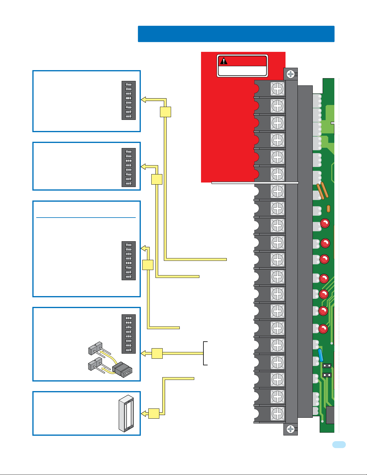
QUICK GUIDE: Terminal Descriptions
See page 24 for main terminal wiring.
• When gate is closed, input will open gate.
• When gate is open and auto close timer
SW 1, switch 4 is turned ON, input will
re-set and hold timer.
• When gate is open and auto close timer
SW 1, switch 4 is turned OFF, input will
close gate.
• When gate is closing, input will reverse gate.
• lf SW 1, switch 3 is ON, functions as a
normal full open input (Normal setting).
• lf SW 1, switch 3 is OFF, input to
terminal #12 becomes the output from the
EXIT loop detector plugged into the EXIT
loop port. (Used for specialized functions).
This input ONLY functions when gate is fully
opened or in the closing cycle.
• When gate is closing: SW 2, switch 5 is OFF, an
input to terminal #15 (e.g.: photo beam gets
obstructed) will reverse and open the gate.
Note: If the auto-close timer is ON, when
gate reaches the open position, timer will
not close the gate. Another input
command is needed to reset and close
the gate.
• When gate is closing: SW 2, switch 5 is
ON, an input to terminal #15 (e.g.: photo
beam gets obstructed) has NO effect on the
gate operator (Set for Shadow input).
SW1
ON
1234 5678
SW1
ON
123 45678
SW1
ON
12345 678
Power - Neutral
Power - Neutral
11
Circuit Board Power
12
24 VAC - 250 ma. max.
12 VAC - 150 ma. max.
Pulse 1 - Primary Operator
Pulse 2 - Secondary Operator
15
Full Open/Open Loop
OPEN - DoorKing 3-Button station ONLY
DANGER
HIGH VOLTAGE!
Motor
Motor
Not Used
Full Open
1
2
3
4
5
6
7
8
9
10
11
12
13
Operation of the circuit board dry relay
contact is dependent on setting of SW 1,
switches 1 and 2.
Relay contacts can be set for Normally
Open (NO) or
Normally Closed (NC)
operation.
Contact rating is
1 amp maximum
at 24-volts DC.
24-volt DC magnetic lock
power is provided constantly
except when the gate is
opening or open (Normally
Closed function). 1 Amp Max.
6050-065-C-2-16
NC
NO
SW1
ON
12345678
CLOSE - DoorKing 3-Button station ONLY
Standard Reverse or Shadow
Dry Relay Contact
16
Dry Relay Contact
24 VDC Maglock Power
Low Voltage Common
18
Low Voltage Common
14
15
16
17
18
19
20
1 2 3 4 5 6 7 8 1 2 3 4 5 6 7 8
NC
NO
3
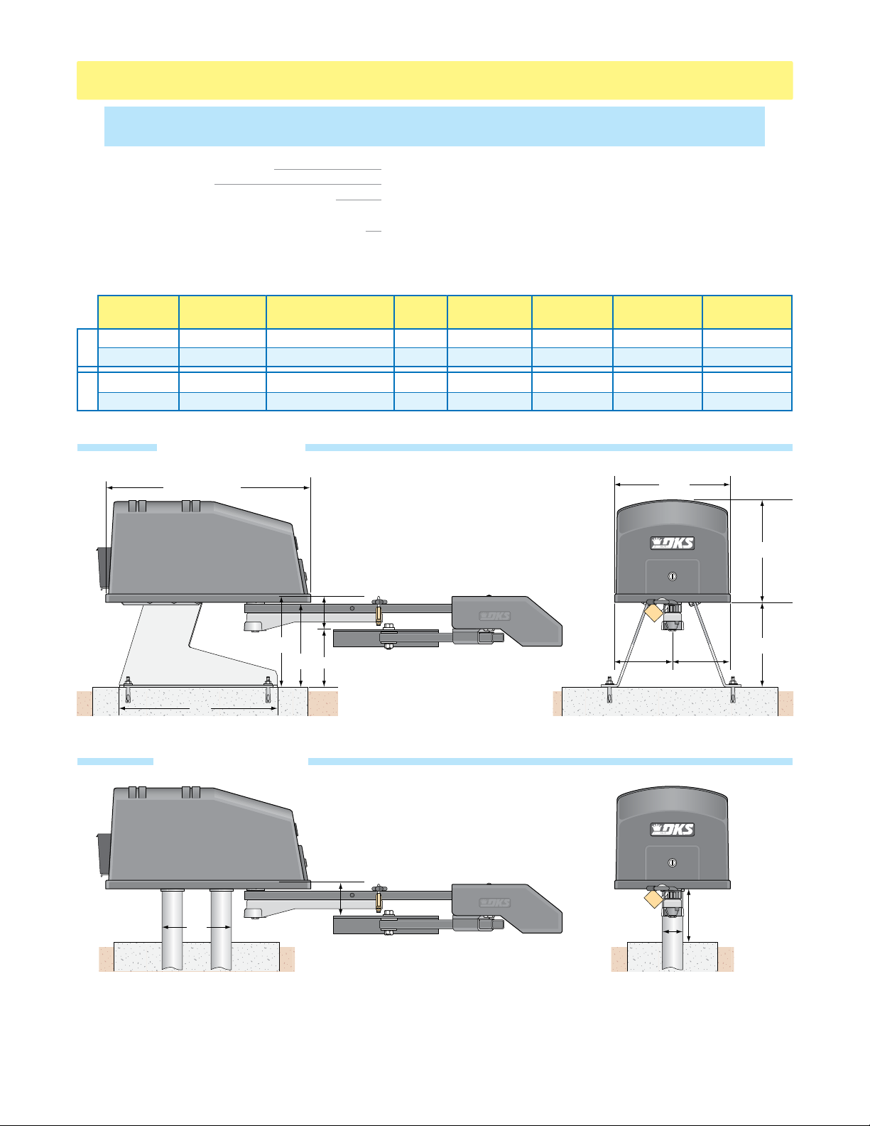
6050 / 6100 SPECIFICATIONS
Use this manual for the Model 6050/6100 operators with circuit board 4502-010 Rev K or higher ONLY.
For operators manufactured July 2011 and later.
UL325 Class of Operation Model 6050 Class I Only ; Model 6100 Class I, II, III, IV
Type of Gate Vehicular Swing Gates Only
Inherent Entrapment Protection Device Inherent Reverse Sensor System (Type A) - Adjustment is NOT needed.
Inherent Adjustable Clutch (Type C) - Adjustment is needed for UL compliance.
External Entrapment Protection Device Inputs Connection inputs for Non-contact Sensor - Photo Sensor (Type B1)
(Monitored Inputs) Connection input for Contact Sensor - Reversing Edge (Type B2)
Installation of ONE MONITORED external entrapment protection device MUST be installed or operator WILL NOT function.
6050
6100
Model #
6050-080
6050-081
6100-080
6100-081
Type
Operator
Primary
Secondary
Primary
Secondary
Horsepower - Volts
1/2 HP - 115 VAC
1/2 HP - 115 VAC
1/2 HP - 115 VAC
1/2 HP - 115 VAC
Pad Mount Kit
P/N 2600-671
23” Standard
11”
9.5”
18”
6”
5”
Amp
4.3
4.3
5.4
5.4
Max Gate
Weight
400 Lbs.
400 Lbs.
500 Lbs.
500 Lbs.
Arm Assembly
Max Gate
Length
10 Ft.
10 Ft.
14 Ft.
14 Ft.
Cycles Per
Hour
10
10
60
60
13.5”
6.75” 6.75”
Speed
90°
12-14 Sec
12-14 Sec
12-14 Sec
12-14 Sec
11”
10.5”
Post Mount Kit
P/N 2600-674
Arm Assembly
5”
11”
DoorKing, Inc. reserves the right to make changes in the products described in this manual without notice and without obligation of DoorKing, Inc. to notify any
persons of any such revisions or changes. Additionally, DoorKing, Inc. makes no representations or warranties with respect to this manual. This manual is
copyrighted, all rights reserved. No portion of this manual may be copied, reproduced, translated, or reduced to any electronic medium without prior written
consent from DoorKing, Inc.
4
2.25”
Distance can vary.
6” minimum.
6050-065-C-2-16

TABLE OF CONTENTS
QUICK GUIDE - DIP-SWITCHES and MAIN TERMINAL
SPECIFICATIONS
ASTM F2200 Standard for Gate Construction
Important Safety Instructions
Instructions regarding intended installation:
Important Notices
UL 325 Entrapment Protection
Glossary
Swing Gate Requirements
Swing Gate Protection
Quick Guide-1 & 2
Previous Page
2-3
SECTION 1 - INSTALLATION 8
1.1 Operator Position
1.2 Post Mount or Pad Mount Base Assembly
1.3 Underground Conduit Requirements
1.4 Pad Mount
1.5 Post Mount
1.6 Arm and Gate Bracket Installation
1.7 Manually Adjust the Open and Closed Gate Positions
1.8 Installation of Warning Signs
1.9 Entrapment Protection Installation REQUIRED
1.10 Gates Opening Wider Than 90°
13-14
2
2
3
4
5
6
7
8
9
10
10
11
11
12
12
15
SECTION 2 - AC POWER TO OPERATOR(S) 16
2.1 High Voltage Wire Runs
2.2 High Voltage Terminal Connection
2.3 Bi-Parting Gates Wiring - Dual Gate Operators
16
16
17
SECTION 3 - ADJUSTMENTS 18
3.1 4502 Circuit Board Description and Adjustments
3.2 DIP-Switch SW 1 & SW 2 Settings
3.3 DIP-Switch Descriptions
3.4 Automatic Open / Close Limit Adjustment
3.5 Clutch Adjustment
3.6 Inherent Reverse Sensor System
SECTION 4 - WIRING
4.1 Main Terminal Description
4.2 Control Wiring
4.3 Auxiliary Terminal Wiring
4.4 Loop Detector Wiring
18
19
20
21
22
22
23
23
24
25
26
SECTION 5 - OPERATING INSTRUCTIONS 27
5.1 Power and Reset Switches
5.2 Shutdown Conditions
5.3 Manual Gate Operation
27
28-29
29-30
SECTION 6 - MAINTENANCE AND TROUBLESHOOTING 31
6050-065-C-2-16
6.1 Maintenance
6.2 Troubleshooting
6.3 Accessory Items
Model 6050/6100’s Wiring Diagrams
31
32-33
34
35-36
1

ASTM F2200 Standard for Gate Construction
Vehicular gates should be constructed and installed in accordance with ASTM F2200; Standard Specification for Automated
Vehicular Gate Construction. For a copy of this standard, contact ASTM directly at 610-832-9585; service@astm.org; or
www.astm.org.
Important Safety Instructions
WARNING - To reduce the risk of injury or death:
1. READ AND FOLLOW ALL INSTRUCTIONS.
2. Never let children operate or play with gate controls. Keep the remote control away from children.
3. Always keep people and objects away from gate. NO ONE SHOULD CROSS THE PATH OF THE MOVING GATE.
4. Test the operator monthly. The gate MUST reverse on contact with a rigid object or stop or reverse when an object
activates the non-contact sensors. After adjusting the force or the limit of travel, retest the gate operator. Failure to adjust
and retest the gate operator properly can increase the risk of injury or death.
5. Use the emergency release only when the gate is not moving.
6. KEEP GATES PROPERLY MAINTAINED. Read the owner's manual. Have a qualified service person make repairs to gate
hardware.
7. The entrance is for vehicles only. Pedestrians must use separate entrance.
8. SAVE THESE INSTRUCTIONS!
Instructions regarding intended installation:
• Install the gate operator only if:
1. The operator is appropriate for the construction of the gate and the usage class of the gate.
2. All openings of a horizontal slide gate are guarded or screened from the bottom of the gate to a minimum of 6 feet
(1.83 m) above the ground to prevent a 2 ¼ inch (57.2 mm) diameter sphere from passing through the openings
anywhere in the gate, and in that portion of the adjacent fence that the gate covers in the open position.
3. All exposed pinch points are eliminated or guarded.
4. Guarding is supplied for exposed rollers.
• The operator is intended for installation only on gates used for vehicles. Pedestrians must be supplied with a separate
access opening. The pedestrian access opening shall be designed to promote pedestrian usage. Locate the gate such that
persons will not come in contact with the vehicular gate during the entire path of travel of the vehicular gate.
• The gate must be installed in a location so that enough clearance is supplied between the gate and adjacent structures
when opening and closing to reduce the risk of entrapment. Swinging gates should not open into public access areas.
• The gate must be properly installed and work freely in both directions prior to the installation of the gate operator. Do not
over-tighten the operator clutch, pressure relief valve or reduce reversing sensitivity to compensate for a damaged gate.
• For gate operators utilizing Type D protection:
1. The gate operator controls must be placed so that the user has full view of the gate area when the gate is moving.
2. A warning placard shall be placed adjacent to the controls.
3. An automatic closing device (such as a timer, loop sensor, or similar device) shall not be employed.
4. No other activation device shall be connected.
• Controls intended for user activation must be located at least six feet (6’) away from any moving part of the gate and
where the user is prevented from reaching over, under, around or through the gate to operate the controls.
Exception: Emergency access controls only accessible by authorized personnel (e.g. fire, police, EMS) may be placed at
any location in the line-of-sight of the gate.
• The Stop and/or Reset button must be located in the line-of-sight of the gate. Activation of the reset control shall not
cause the operator to start.
• A minimum of two (2) WARNING SIGNS shall be installed, one on each side of the gate where easily visible.
• For gate operators utilizing a non-contact sensor:
1. See the instructions on the placement of non-contact sensors for each type of application.
2. Care shall be exercised to reduce the risk of nuisance tripping, such as when a vehicle trips the sensor while the gate
is still moving in the opening direction.
3. One or more non-contact sensors shall be located where the risk of entrapment or obstruction exist, such as the
perimeter reachable by a moving gate or barrier.
2
6050-065-C-2-16

• For gate operators utilizing contact sensors:
1. One or more contact sensors shall be located where the risk of entrapment or obstruction exist, such as at the
leading edge, trailing edge, and post mounted both inside and outside of a vehicular horizontal slide gate.
2. One or more contact sensors shall be located at the bottom edge of a vehicular vertical lift gate.
3. One or more contact sensors shall be located at the pinch point of a vehicular vertical pivot gate.
4. A hardwired contact sensor shall be located and its wiring arranged so that the communication between the sensor
and the gate operator is not subjected to mechanical damage.
5. A wireless contact sensor such as one that transmits radio frequency (RF) signals to the gate operator for
entrapment protection functions shall be located where the transmission of the signals are not obstructed or
impeded by building structures, natural landscaping or similar obstructions. A wireless contact sensor shall function
under the intended end-use conditions.
6. One or more contact sensors shall be located at the bottom edge of a vertical barrier (arm).
Important Notices
Vehicular gate operator products provide convenience and security. However, gate operators must use high levels of force
to move gates and most people underestimate the power of these systems and do not realize the potential hazards associated with an incorrectly designed or installed system. These hazards may include:
• Pinch points
• Entrapment areas
• Reach through hazards
• Absence of entrapment protection devices
• Improperly located access controls
• Absence of vehicle protection devices
• Absence of controlled pedestrian access
In addition to these potential hazards, automated vehicular gate systems must be installed in accordance with the UL-325
Safety Standard and the ASTM F2200 Construction Standard. Most lay persons are unaware of, or are not familiar with,
these standards. If an automated vehicular gate system is not properly designed, installed, used and maintained, serious
injuries or death can result. Be sure that the installer has instructed you on the proper operation of the gate and gate
operator system.
Be sure that the installer has trained you about the basic functions of the required reversing systems associated with your
gate operating system and how to test them. These include reversing loops, inherent reversing system, electric edges,
photoelectric cells, or other external devices.
• This Owner’s Manual is your property. Keep it in a safe place for future reference.
• Be sure that all access control devices are installed a minimum distance of 6 feet away from the gate and gate
operator, or in such a way that a person cannot touch the gate or gate operator while using the device. If access
control devices are installed in violation of these restrictions, immediately remove the gate operator from service
and contact your installing dealer.
• Loops and loop detectors, photo-cells or other equivalent devices must be installed to prevent the gate from
closing on vehicular traffic.
• The speed limit for vehicular traffic through the gate area is 5 MPH. Install speed bumps and signs to keep
vehicular traffic from speeding through the gate area. Failure to adhere to posted speed limits can result in
damage to the gate, gate operator, and to the vehicle.
• Be sure that all persons who will use the gate system are familiar with the proper use of the gate and gate
operator and are familiar with the possible hazards associated with the gate system.
• Be sure that warning signs are permanently installed on both sides of the gate in an area where they are fully
visible to traffic.
• It is your responsibility to periodically check all entrapment protection devices. If any of these devices are
observed to function improperly, remove the operator from service immediately and contact your installing or
servicing dealer.
• Follow the recommended maintenance schedule.
• Do not allow children to play in the area of the operator or to play with any gate-operating device.
• To remove the gate operator from service, operate the gate to the full open position and then shut off power to
the operator at the service panel.
6050-065-C-2-16
3
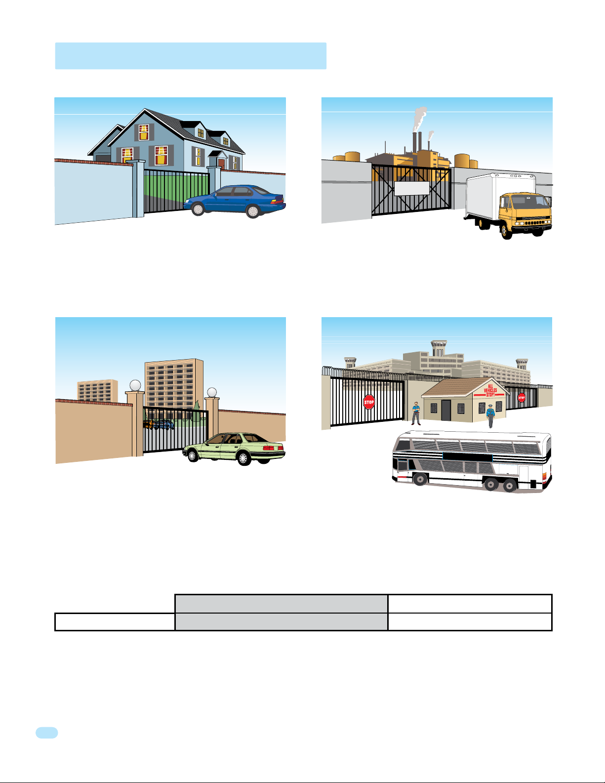
UL 325 Entrapment Protection
UL 325 Classifications
Authorized
Personnel ONLY
Class I - Residential
Vehicular Gate Operator
A vehicular gate operator (or system) intended for use in garages
or parking areas associated with a residence of one-to four single
families.
Class II - Commercial/General Access
Vehicular Gate Operator
A vehicular gate operator (or system) intended for use in a
commercial location or building such as a multi-family housing
unit (five or more single family units), hotel, garages, retail store,
or other buildings accessible by or servicing the general public.
Class III - Industrial/Limited Access
Vehicular Gate Operator
A vehicular gate operator (or system) intended for use in an
industrial location or building such as a factory or loading dock
area or other locations not accessible by or intended to service
the general public.
STATE PRISON
Class IV Restricted Access
Vehicular Gate Operator
A vehicular gate operator (or system) intended for use in a
guarded industrial location or building such as an airport security
area or other restricted access locations not servicing the general
public, in which unauthorized access is prevented via supervision
by security personnel.
Gate Operator Category
Effective January 12, 2016
Entrapment Protection Types
Type A - Inherent entrapment protection system.
Type B1 - Non-contact sensor (photoelectric sensor or the equivalent).
Type B2 - Contact sensor (edge device or equivalent).
Type C - Inherent force limiting, inherent adjustable clutch or inherent pressure relief device.
Type D - Actuating device requiring constant pressure to maintain opening or closing motion of the gate.
* B1 and B2 means of entrapment protection must be MONITORED.
4
Horizontal Slide, Vertical Lift, Vertical Pivot Swing, Vertical Barrier (Arm)
A, B1*, B2* or D A, B1*, B2*, C or D
Vertical Barrier Note: Barrier gate operators (arm)
that is not intended to move toward a rigid object
closer than 16 inches (406 mm) are not required to
be provided with a means of entrapment protection.
6050-065-C-2-16

Glossary
GATE - A moving barrier such as a swinging, sliding, raising, lowering, or the like, barrier, that is a stand-alone passage
barrier or is that portion of a wall or fence system that controls entrance and/or egress by persons or vehicles and
completes the perimeter of a defined area.
RESIDENTIAL VEHICULAR GATE OPERATOR – CLASS I - A vehicular gate operator (or system) intended for use in a home
of one-to four single family dwelling, or garage or parking area associated therewith.
COMMERCIAL / GENERAL ACCESS VEHICULAR GATE OPERATOR - CLASS II - A vehicular gate operator (or system)
intended for use in a commercial location or building such as a multi-family housing unit (five or more single family units),
hotels, garages, retail store, or other building servicing the general public.
INDUSTRIAL / LIMITED ACCESS VEHICULAR GATE OPERATOR - CLASS III - A vehicular gate operator (or system)
intended for use in an industrial location or building such as a factory or loading dock area or other locations not intended
to service the general public.
RESTRICTED ACCESS VEHICULAR GATE OPERATOR - CLASS IV - A vehicular gate operator (or system) intended for use in
a guarded industrial location or building such as an airport security area or other restricted access locations not servicing
the general public, in which unauthorized access is prevented via supervision by security personnel.
VEHICULAR BARRIER (ARM) OPERATOR (OR SYSTEM) - An operator (or system) that controls a cantilever type device (or
system), consisting of a mechanical arm or barrier that moves in a vertical arc, intended for vehicular traffic flow at
entrances or exits to areas such as parking garages, lots or toll areas.
VEHICULAR HORIZONTAL SLIDE-GATE OPERATOR (OR SYSTEM) - A vehicular gate operator (or system) that controls a
gate which slides in a horizontal direction that is intended for use for vehicular entrance and exit to a drive, parking lot, or
the like.
VEHICULAR SWING-GATE OPERATOR (OR SYSTEM) - A vehicular gate operator (or system) that controls a gate which
moves in an arc in a horizontal plane that is intended for use for vehicular entrance and exit to a drive, parking lot, or the
like.
SYSTEM - In the context of these requirements, a system refers to a group of interacting devices intended to perform a
common function.
WIRED CONTROL - A control implemented in a form of fixed physical interconnections between the control, the associated
devices, and an operator to perform predetermined functions in response to input signals.
WIRELESS CONTROL - A control implemented in means other than fixed physical interconnections (such as radio waves or
infrared beams) between the control, the associated devices, and an operator to perform predetermined functions in
response to input signals.
INHERENT ENTRAPMENT PROTECTION SYSTEM - A system, examples being a motor current or speed sensing system,
which provides protection against entrapment upon sensing an object and is incorporated as a permanent and integral part
of the operator.
EXTERNAL ENTRAPMENT PROTECTION DEVICE - A device, examples being an edge sensor, a photoelectric sensor, or
similar entrapment protection device, which provides protection against entrapment when activated and is not incorporated
as a permanent part of an operator.
ENTRAPMENT - The condition when an object is caught or held in a position that increases the risk of injury.
6050-065-C-2-16
5
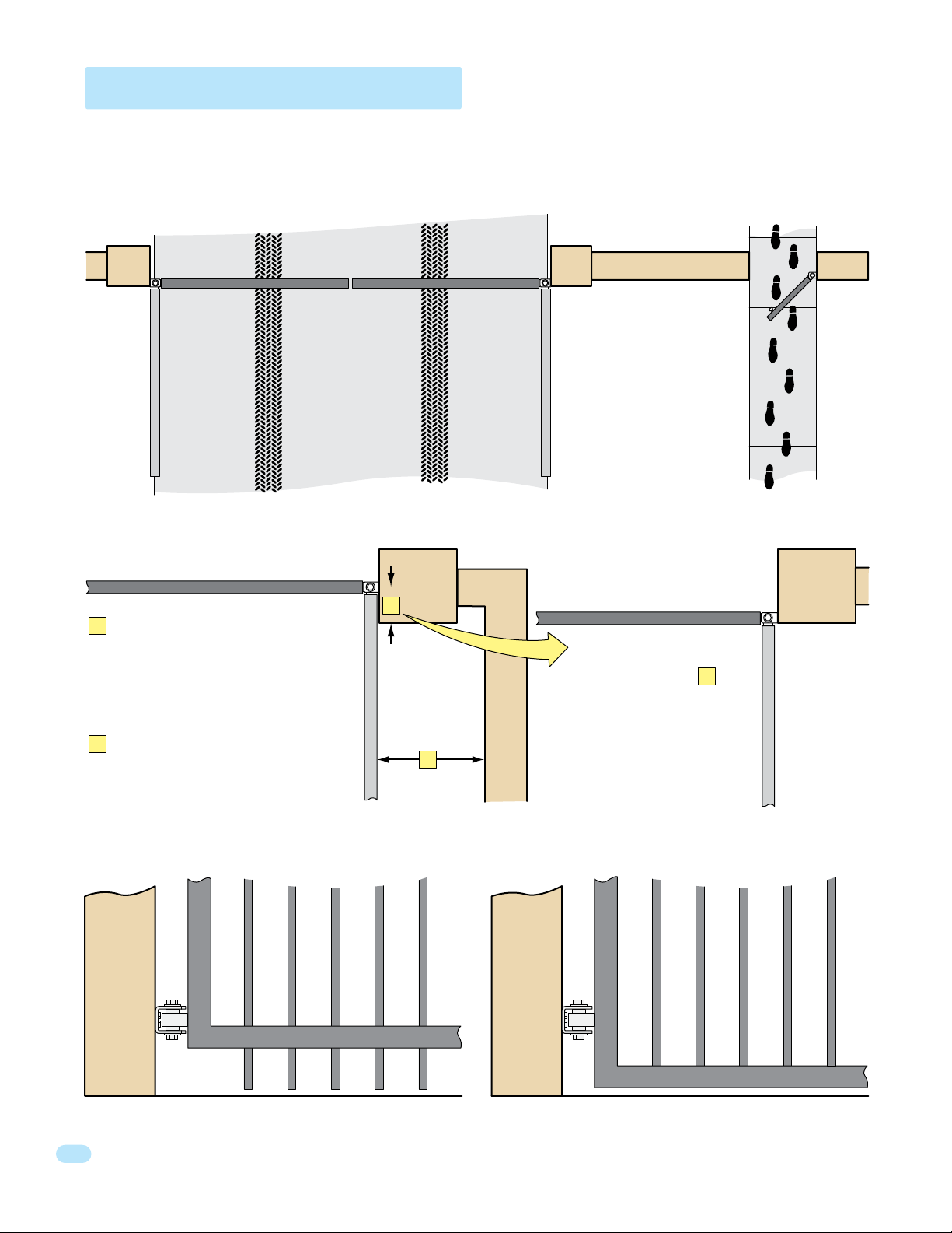
Swing Gate Requirements
The operator is intended for installation only on gates used for vehicles. Pedestrians must be supplied with a separate
access opening. The pedestrian access opening shall be designed to promote pedestrian usage. Locate the gate such that
persons will not come in contact with the vehicular gate during the entire path of travel of the vehicular gate.
(ref. UL325 56.8.4.b)
Closed Gates
Closed Gate
If distance is greater than 4 inches,
A
entrapment protection for this area is
required. ASTM F2200 7.1.1.1
If distance is less than 16 inches,
B
entrapment protection in this area
is required. ASTM F2200 7.1.1.2
Not Allowed OK
A
B
Opened Gate
Closed Gate
With the hinge mounted on
the corner of the pilaster,
the entrapment area is
eliminated and protection
is NOT required for this
area.
A
Opened Gate
Gates shall have smooth bottom edges, with vertical bottom edged protrusions not exceeding 0.50 inches. ASTM F2200 4.3
6
6050-065-C-2-16
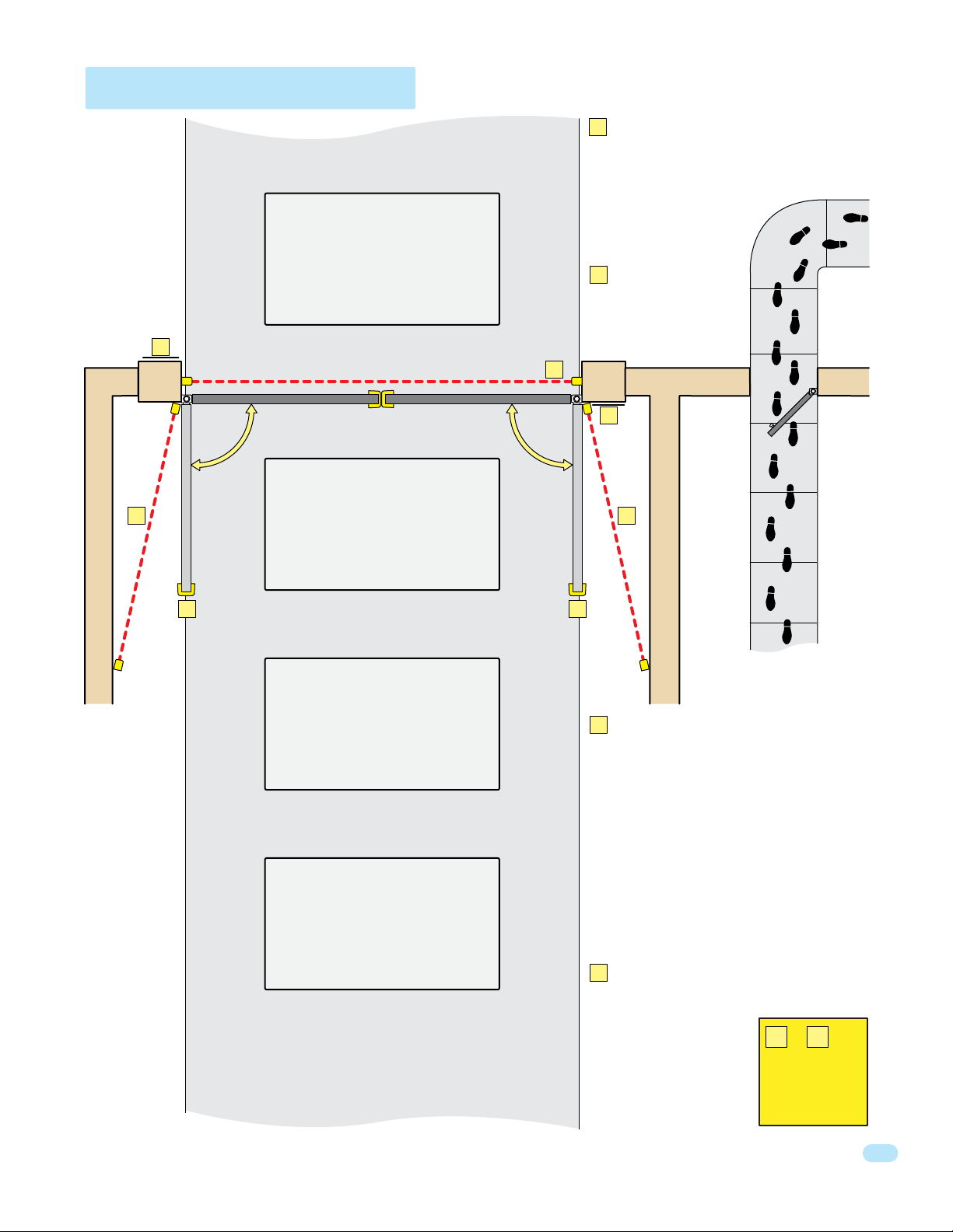
Swing Gate Protection
Reverse Loop
Minimizes the potential of the gate
closing when a vehicle is present.
Number and placement of loops is
dependent on the application.
D
Shadow Loop
E
Provides a hold open command to
the operator(s) only if the gate(s)
are at the full open position.
C
Standard
Non-contact Sensor
Minimizes the potential
of the gate closing on
vehicular or other traffic
that loops cannot sense.
D
Warning Signs
Permanently mounted
and easily visible from
either side of the gate.
C
D
E
F F
Reverse Loop
Minimizes the potential of the gate
closing when a vehicle is present.
Number and placement of loops is
dependent on the application.
Automatic Exit Loop
(Optional) will provide an open
command to the gate operator(s)
when a vehicle is exiting the
property.
E
Monitored
Non-contact
Sensor
Minimizes the potential
of the gate striking
vehicular or other traffic
that loops cannot sense.
Monitored device helps
protect against
entrapment when
needed.
F
Contact Sensor
Minimizes the potential
of the gate striking
vehicular or other traffic
that loops cannot sense.
Monitored device helps
protect against
entrapment when
needed.
Separate
Pedestrian
Walkway
Located so
pedestrians
cannot come in
contact with the
vehicular gate.
or is
E F
REQUIRED
for operator
to function.
6050-065-C-2-16
7
SECTION 1 - INSTALLATION
Prior to beginning the installation of the swing gate operator, we suggest that you become familiar with the
instructions, illustrations, and wiring guide-lines in this manual. This will help insure that your installation is
performed in an efficient and professional manner compliant with UL 325 safety and ASTM F2200 construction
standards.
The proper installation of the vehicular swing gate operator is an extremely important and integral part of the
overall access control system. Check all local building ordinances and building codes prior to installing this
operator. Be sure your installation is in compliance with local codes.
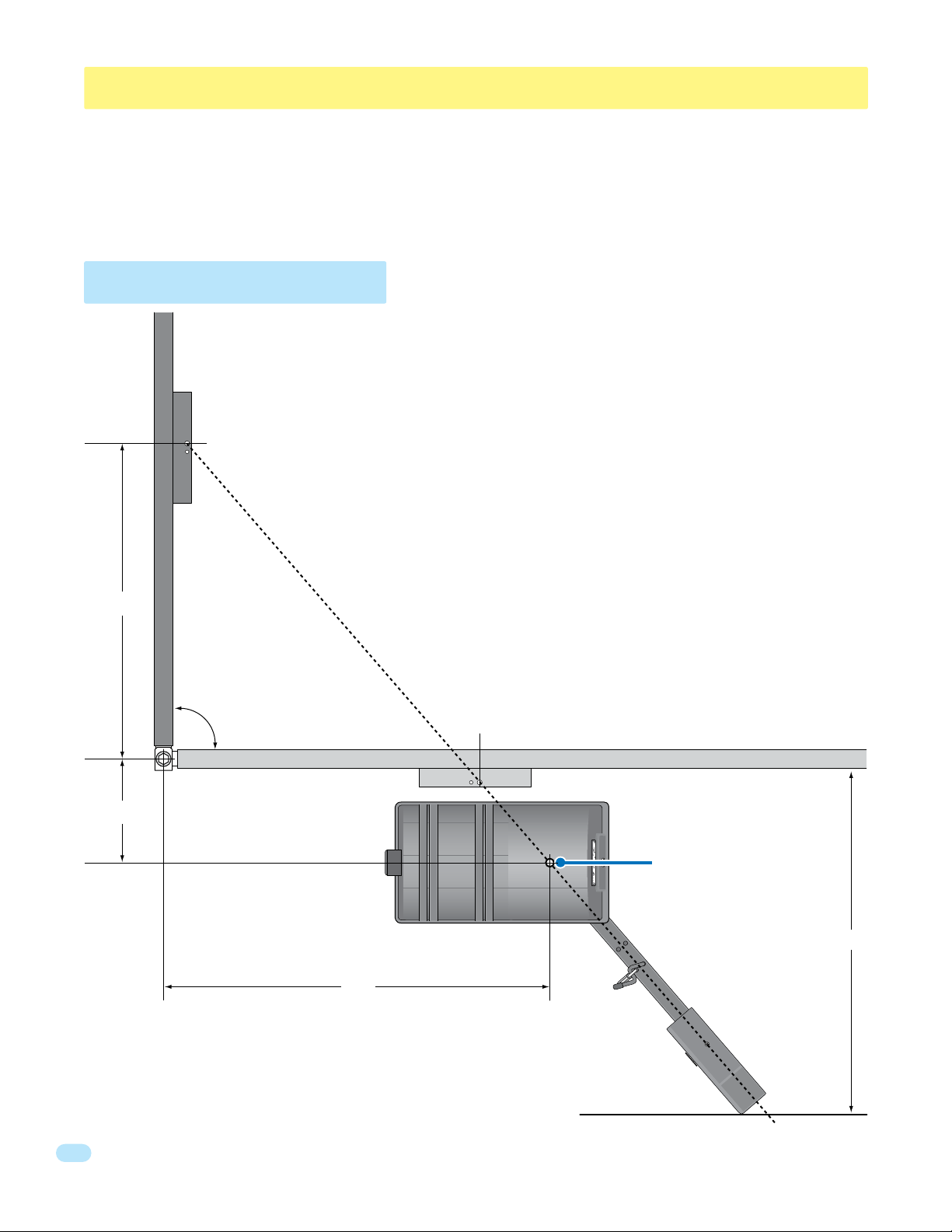
1.1 Operator Position
For pad or post mount with
the gate opening 90°.
See 1.10 for gate’s opening wider than 90°.
Gate
Bracket
An imaginary straight line drawn
from the closed gate bracket
through the open gate bracket
MUST intersect the
operator output shaft.
34”
12”
90°
Closed Gate
Open Gate
Note: The operator can be placed further away from the open gate than
shown as long as the imaginary straight line drawn from the closed gate
bracket through the open gate bracket intersects the operator output shaft.
43”
Note: 2” thick gate Illustrated.
Operator
Output Shaft
35”
Minimum distance
required for arm
clearance in the
open position.
8
6050-065-C-2-16
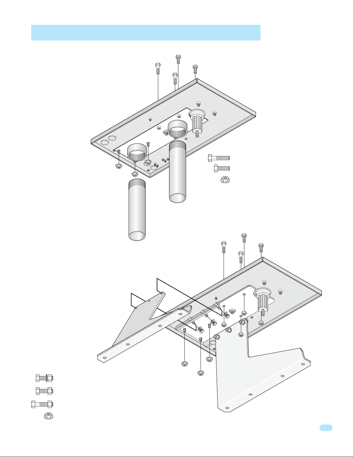
1.2 Post Mount or Pad Mount Base Assembly
(2) 1 1/2” bolts through the main
gear bracket mounting holes.
Post Support Base
Screw the posts to the support
plate and mount into concrete
BEFORE attaching the operator.
Bottom of Operator
Support
Plate
(2) 1” bolts through the main gear bracket mounting holes.
Hardware for Post Mount:
(2) 1 1/2 inch bolts. For support plate.
(2) 1 inch bolts. For support plate.
(3) Non-slip nuts. For existing threaded
studs on bottom of operator.
Pad Support Base
Remove the cover from the
operator and GENTLY place
the operator on its side before
attaching the pad base.
Hardware for Pad Mount:
(6) 1 inch bolts, lockwashers and nuts for support legs.
(2) 1 inch bolts and nuts for support plate.
S
Leg
(2) 1 1/2” bolts through the main
gear bracket mounting holes.
Right
upport
Bottom of Operator
e
Support
Plat
1” Bolts
Left Support Leg
(2) 1” bolts through the main
gear bracket mounting holes.
6050-065-C-2-16
(2) 1 1/2 inch bolts and nuts. For support plate.
(3) Non-slip nuts. For existing threaded studs on bottom of operator.
9
 Loading...