

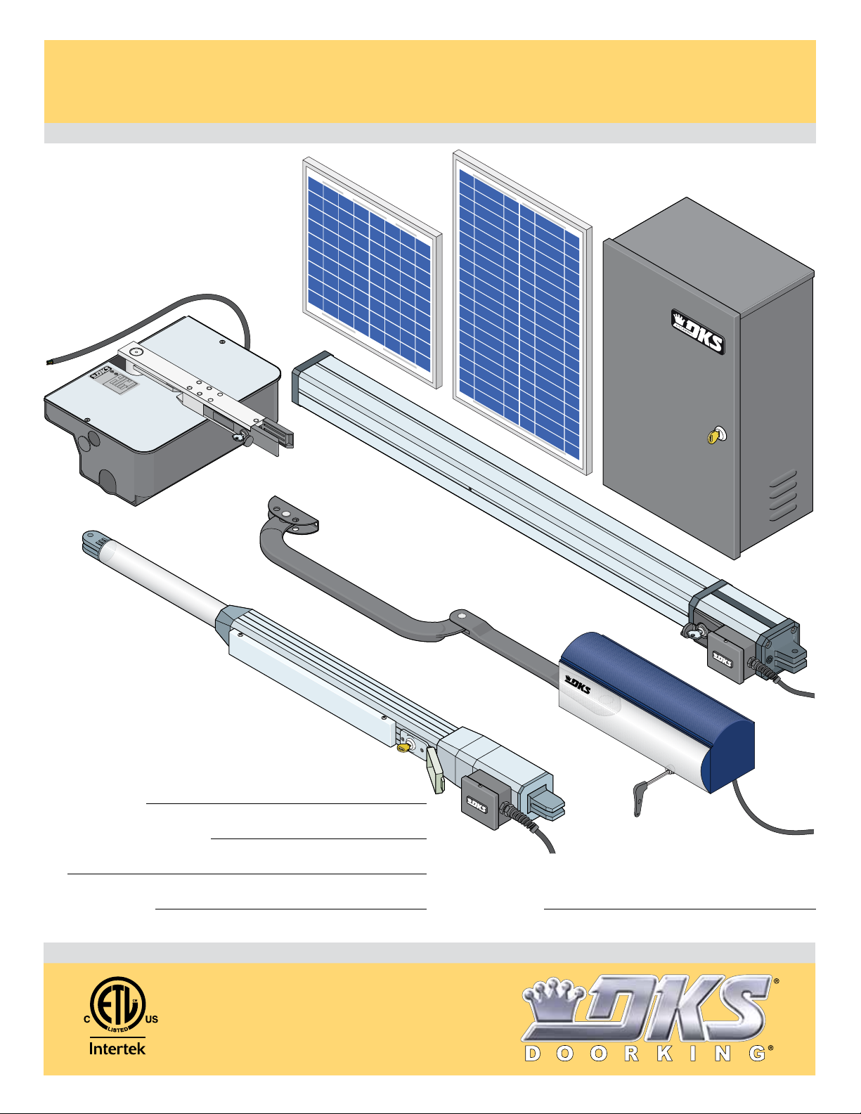
DoorKing 6002, 6003, 6004, 6400 Owners And Wiring Manual
Wiring / Owner’s
Solar Control Box for
24
Volt
20 Watt
Sola
r
Pane
l
24
Volt
10 Watt
Sola
r
Pane
l
Solar Control Box for
Solar Control Box for
Manual
6002, 6003, 6004 and 6400 gate operators
Use this manual for circuit board 4302-010 Revision N or higher.
EXTERNAL ENTRAPMENT PROTECTION
MUST be installed or the gate operator
WILL NOT function.
24 Volt
10 Watt
Solar
Panel
82
3
3
5
TO
OR
S
5
2
M
7
3
R
4
-
RAT
2
L
O
.
F
TO
/U
I
O
N
S
N
O
P
N
C
E OPE
2
H
.
A
T
IFIED
T
R
GA
C22
E
C
R
SA
A
/C
E
N
S
A
CA
H
HICUL
P
z
S
VE
H
LAS
L
C
E
D
CA
,
L
d
MO
A
o
o
w
ERI
e
l
S
g
TS
AD
n
L
I
,
LO
VO
c.
E
S60
n
T
A
, I
g
G
AMP
n
X
Ki
r
o
MA
o
D
6400
24 Volt
20 Watt
Solar
Panel
4302-067-N-1-16
Solar
Control
Box
Date Installed:
Installer/Company Name:
Phone Number:
Leave Manual with Owner
6003
6002
E
LOS
C
N
E
P
O
Circuit Board
Serial Number
and Revision Letter:
DOO
RK
IN
G
6004
Copyright 2016 DoorKing, Inc. All rights reserved.
UL 325 Compliant
Copyright 2009 DoorKing, Inc. All rights reserved.

tec
S
G
S
OS
2
OS
G
COM
.
p
N
d
N
d
SOLAR CONTROL BOX SPECIFICATIONS
c
S
G
S
OS
2
OS
G
COM
.
N
d
N
d
Class of Operation Models 6002, 6003, 6004 and 6400 - UL325 Class I
Type of Gate Residential Vehicular Automated Gates Only
Voltage / Phase 24 Volt Solar Input Power – 24 VDC Output Power to Gate Operators
Battery Capacity Two - 12 Volt 18 Amp/Hour Dry Cell OR Two - 12 Volt 35 Amp/Hour Dry Cell
Solar Panel Voltage 24 Volt 10 Watt for 18 Amp/Hour Dry Cells OR 24 Volt 20 Watt for 35 Amp/Hour Dry Cells
Circuit Board Model 4302-010 revision N or higher.
Inherent Entrapment Protection Device Inherent Reverse Sensor System (Type A)
External Entrapment Protection Device Inputs Connection inputs for Non-contact Sensor - Photo Sensor (Type B1)
(Monitored Inputs) Connection input for Contact Sensor - Reversing Edge (Type B2)
TWO (2) Entrapment Protection Devices are REQUIRED for UL 325 compliance.
Type B1 and B2 MUST be MONITORED when used.
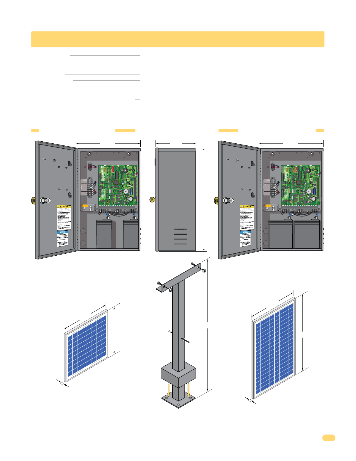
18 Amp/Hr Control Box
P/N 4302-114
ot Use
Not Used
Not Used
ot Use
Relay N.O.
Relay N.O
en
Relay COM
Relay
24 V NEG
24 V NE
Full Open
Full O
24 V POS
4 V P
Solar POS
olar P
Solar NEG
olar NE
PUSH TO OPERATE
PUS
technician use only
ON
1 23 4 56 7 8 91011121314151617181920
OFF
12 V
Battery
18 Amp/Hr
Optional 24 Volt 10 Watt
Solar Panel only for
18 Amp/Hr Batteries
P/N 2000-077
13.8”
11.8”
No Batteries Control Box
P/N 4302-113
8.25”13.25”
B
12 V
Battery
18 Amp/Hr
Optional
Mounting
Post Kit
for Control
Box
P/N 1000-045
21.25”
33”
35 Amp/Hr Control Box
P/N 4302-115
13.25”
ot Use
Not Used
Not Used
ot Use
Relay N.O.
Relay N.O
Relay COM
Relay
24 V NEG
24 V NE
Full Open
Full Open
24 V POS
4 V P
Solar POS
olar P
Solar NEG
olar NE
PUSH TO OPERATE
PUS
te
technician use only
ON
1 2 3 4 5 6 7 8 91011121314151617181920
OFF
12 V
35 Amp/Hr
Battery
B
12 V
35 Amp/Hr
Battery
Optional 24 Volt 20 Watt
Solar Panel only for
35 Amp/Hr Batteries
P/N 2000-076
13.8”
21.8”
.98”
.98”
DoorKing, Inc. reserves the right to make changes in the products described in this manual without notice and without obligation of DoorKing, Inc. to notify any persons
of any such revisions or changes. Additionally, DoorKing, Inc. makes no representations or warranties with respect to this manual. This manual is copyrighted, all rights
reserved. No portion of this manual may be copied, reproduced, translated, or reduced to any electronic medium without prior written consent from DoorKing, Inc.
4302-067-N-1-16
1

TABLE OF CONTENTS
SPECIFICATIONS 1
Solar Control Box Specifications
ASTM F2200 Standard for Gate Construction
Important Safety Instructions
Instructions regarding intended installation:
Important Notices
UL 325 Entrapment Protection
Glossary
Swing Gate Requirements
Swing Gate Protection
SECTION 1 - SOLAR PANEL INSTALLATION CONSIDERATIONS 9
1.1 Solar Panel Concerns BEFORE Installation
1.2 Solar Panel Positioning
SECTION 2 - WIRING 11
2.1 Control Box Wiring Overview
2.2 Wiring Operators to 4302 Circuit Board
2.3 Entrapment Protection Wiring
2.4 Full Open Terminal Wiring
2.5 Loop Detector Wiring
2.6 Battery Wiring
2.7 Solar Panel Wiring
3-4
10
11
12
13
14
15
16
17
1
3
3
4
5
6
7
8
9
SECTION 3 - ADJUSTMENTS 18
3.1 3402 Circuit Board Description and Adjustments
3.2 DIP-Switches
3.3 Limit Sensors Adjustment - Select your specific operator
6002 Limit Sensors ONLY
6003 Limit Sensors ONLY
6004 Limit Switches ONLY
6400 Limit Sensors ONLY
3.4 Inherent Reverse Sensor Adjustment
3.5 Shutdown Conditions
Soft Shutdown
Hard Shutdown (Alarm Activated)
18
19-20
21-23
24
25-26
SECTION 4 - MAINTENANCE AND TROUBLESHOOTING 27
4.1 Maintenance
4.2 Diagnostics Check
4.3 Troubleshooting
4.4 Accessory Items
Solar Control Box Schematics
IMPORTANT INFORMATION FOR OWNER
Shut-Off Power to Operator OR Shut-OFF Alarm
Manually Operating the Gate - NO Power
27
27-28
28-29
29
30
31
31
32
2
4302-067-N-1-16

ASTM F2200 Standard for Gate Construction
Vehicular gates should be constructed and installed in accordance with ASTM F2200; Standard Specification for Automated
Vehicular Gate Construction. For a copy of this standard, contact ASTM directly at 610-832-9585; service@astm.org; or
www.astm.org.
Important Safety Instructions
WARNING - To reduce the risk of injury or death:
1. READ AND FOLLOW ALL INSTRUCTIONS.
2. Never let children operate or play with gate controls. Keep the remote control away from children.
3. Always keep people and objects away from gate. NO ONE SHOULD CROSS THE PATH OF THE MOVING GATE.
4. Test the operator monthly. The gate MUST reverse on contact with a rigid object or stop or reverse when an object
activates the non-contact sensors. After adjusting the force or the limit of travel, retest the gate operator. Failure to adjust
and retest the gate operator properly can increase the risk of injury or death.
5. Use the emergency release only when the gate is not moving.
6. KEEP GATES PROPERLY MAINTAINED. Read the owner's manual. Have a qualified service person make repairs to gate
hardware.
7. The entrance is for vehicles only. Pedestrians must use separate entrance.
8. SAVE THESE INSTRUCTIONS!
Instructions regarding intended installation:
• Install the gate operator only if:
1. The operator is appropriate for the construction of the gate and the usage class of the gate.
2. All openings of a horizontal slide gate are guarded or screened from the bottom of the gate to a minimum of 6 feet
(1.83 m) above the ground to prevent a 2 ¼ inch (57.2 mm) diameter sphere from passing through the openings
anywhere in the gate, and in that portion of the adjacent fence that the gate covers in the open position.
3. All exposed pinch points are eliminated or guarded.
4. Guarding is supplied for exposed rollers.
• The operator is intended for installation only on gates used for vehicles. Pedestrians must be supplied with a separate
access opening. The pedestrian access opening shall be designed to promote pedestrian usage. Locate the gate such that
persons will not come in contact with the vehicular gate during the entire path of travel of the vehicular gate.
• The gate must be installed in a location so that enough clearance is supplied between the gate and adjacent structures
when opening and closing to reduce the risk of entrapment. Swinging gates should not open into public access areas.
• The gate must be properly installed and work freely in both directions prior to the installation of the gate operator. Do not
over-tighten the operator clutch, pressure relief valve or reduce reversing sensitivity to compensate for a damaged gate.
• For gate operators utilizing Type D protection:
1. The gate operator controls must be placed so that the user has full view of the gate area when the gate is moving.
2. A warning placard shall be placed adjacent to the controls.
3. An automatic closing device (such as a timer, loop sensor, or similar device) shall not be employed.
4. No other activation device shall be connected.
• Controls intended for user activation must be located at least six feet (6’) away from any moving part of the gate and
where the user is prevented from reaching over, under, around or through the gate to operate the controls. Outdoor or
easily accessible controls should have a security feature to prevent unauthorized use.
• The Stop and/or Reset button must be located in the line-of-sight of the gate. Activation of the reset control shall not
cause the operator to start.
• A minimum of two (2) WARNING SIGNS shall be installed, one on each side of the gate where easily visible.
• For gate operators utilizing a non-contact sensor:
1. See the instructions on the placement of non-contact sensors for each type of application.
2. Care shall be exercised to reduce the risk of nuisance tripping, such as when a vehicle trips the sensor while the gate
is still moving in the opening direction.
3. One or more non-contact sensors shall be located where the risk of entrapment or obstruction exist, such as the
perimeter reachable by a moving gate or barrier.
4302-067-N-1-16
3

• For gate operators utilizing contact sensors:
1. One or more contact sensors shall be located where the risk of entrapment or obstruction exist, such as at the
leading edge, trailing edge, and post mounted both inside and outside of a vehicular horizontal slide gate.
2. One or more contact sensors shall be located at the bottom edge of a vehicular vertical lift gate.
3. One or more contact sensors shall be located at the pinch point of a vehicular vertical pivot gate.
4. A hardwired contact sensor shall be located and its wiring arranged so that the communication between the sensor
and the gate operator is not subjected to mechanical damage.
5. A wireless contact sensor such as one that transmits radio frequency (RF) signals to the gate operator for
entrapment protection functions shall be located where the transmission of the signals are not obstructed or
impeded by building structures, natural landscaping or similar obstructions. A wireless contact sensor shall function
under the intended end-use conditions.
6. One or more contact sensors shall be located at the bottom edge of a vertical barrier (arm).
Important Notices
Vehicular gate operator products provide convenience and security. However, gate operators must use high levels of force
to move gates and most people underestimate the power of these systems and do not realize the potential hazards associated with an incorrectly designed or installed system. These hazards may include:
• Pinch points
• Entrapment areas
• Reach through hazards
• Absence of entrapment protection devices
• Improperly located access controls
• Absence of vehicle protection devices
• Absence of controlled pedestrian access
In addition to these potential hazards, automated vehicular gate systems must be installed in accordance with the UL 325
Safety Standard and the ASTM F2200 Construction Standard. Most lay persons are unaware of, or are not familiar with,
these standards. If an automated vehicular gate system is not properly designed, installed, used and maintained, serious
injuries or death can result. Be sure that the installer has instructed you on the proper operation of the gate and gate
operator system.
Be sure that the installer has trained you about the basic functions of the required reversing systems associated with your
gate operating system and how to test them. These include reversing loops, inherent reversing system, electric edges,
photoelectric cells, or other external devices.
• This Owner’s Manual is your property. Keep it in a safe place for future reference.
• Be sure that all access control devices are installed a minimum distance of 6 feet away from the gate and gate
operator, or in such a way that a person cannot touch the gate or gate operator while using the device. If access
control devices are installed in violation of these restrictions, immediately remove the gate operator from service
and contact your installing dealer.
• Loops and loop detectors, photo-cells or other equivalent devices must be installed to prevent the gate from
closing on vehicular traffic.
• The speed limit for vehicular traffic through the gate area is 5 MPH. Install speed bumps and signs to keep
vehicular traffic from speeding through the gate area. Failure to adhere to posted speed limits can result in
damage to the gate, gate operator, and to the vehicle.
• Be sure that all persons who will use the gate system are familiar with the proper use of the gate and gate
operator and are familiar with the possible hazards associated with the gate system.
• Be sure that warning signs are permanently installed on both sides of the gate in an area where they are fully
visible to traffic.
• It is your responsibility to periodically check all entrapment protection devices. If any of these devices are
observed to function improperly, remove the operator from service immediately and contact your installing or
servicing dealer.
• Follow the recommended maintenance schedule.
• Do not allow children to play in the area of the operator or to play with any gate-operating device.
• To remove the gate operator from service, operate the gate to the full open position and then shut off power to
the operator at the service panel.
4
4302-067-N-1-16
UL 325 Entrapment Protection
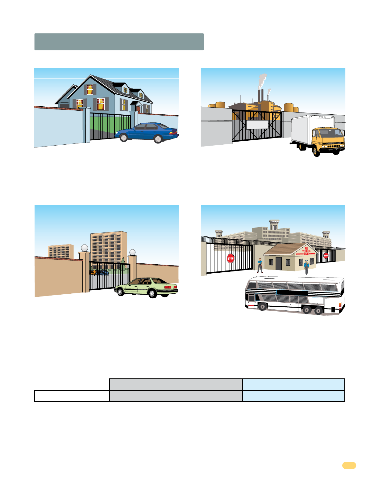
UL 325 Classifications
Authorized
Personnel ONLY
Class I - Residential
Vehicular Gate Operator
A vehicular gate operator (or system) intended for use in garages
or parking areas associated with a residence of one-to four single
families.
Class II - Commercial/General Access
Vehicular Gate Operator
A vehicular gate operator (or system) intended for use in a
commercial location or building such as a multi-family housing
unit (five or more single family units), hotel, garages, retail store,
or other buildings accessible by or servicing the general public.
Class III - Industrial/Limited Access
Vehicular Gate Operator
A vehicular gate operator (or system) intended for use in an
industrial location or building such as a factory or loading dock
area or other locations not accessible by or intended to service
the general public.
STATE PRISON
Class IV Restricted Access
Vehicular Gate Operator
A vehicular gate operator (or system) intended for use in a
guarded industrial location or building such as an airport security
area or other restricted access locations not servicing the general
public, in which unauthorized access is prevented via supervision
by security personnel.
Effective January 12, 2016
Entrapment Protection Types
Type A - Inherent entrapment protection system.
Type B1 - Non-contact sensor (photoelectric sensor or the equivalent).
Type B2 - Contact sensor (edge device or equivalent).
Type C - Inherent force limiting, inherent adjustable clutch or inherent pressure relief device.
Type D - Actuating device requiring constant pressure to maintain opening or closing motion of the gate.
* B1 and B2 means of entrapment protection must be MONITORED.
4302-067-N-1-16
Gate Operator Category
Horizontal Slide, Vertical Lift, Vertical Pivot Swing, Vertical Barrier (Arm)
A, B1*, B2* or D A, B1*, B2*, C or D
Vertical Barrier Note: Barrier gate operators (arm)
that is not intended to move toward a rigid object
closer than 16 inches (406 mm) are not required to
be provided with a means of entrapment protection.
5

Glossary
GATE - A moving barrier such as a swinging, sliding, raising, lowering, or the like, barrier, that is a stand-alone passage
barrier or is that portion of a wall or fence system that controls entrance and/or egress by persons or vehicles and
completes the perimeter of a defined area.
RESIDENTIAL VEHICULAR GATE OPERATOR – CLASS I - A vehicular gate operator (or system) intended for use in a home
of one-to four single family dwelling, or garage or parking area associated therewith.
COMMERCIAL / GENERAL ACCESS VEHICULAR GATE OPERATOR - CLASS II - A vehicular gate operator (or system)
intended for use in a commercial location or building such as a multi-family housing unit (five or more single family units),
hotels, garages, retail store, or other building servicing the general public.
INDUSTRIAL / LIMITED ACCESS VEHICULAR GATE OPERATOR - CLASS III - A vehicular gate operator (or system)
intended for use in an industrial location or building such as a factory or loading dock area or other locations not intended
to service the general public.
RESTRICTED ACCESS VEHICULAR GATE OPERATOR - CLASS IV - A vehicular gate operator (or system) intended for use in
a guarded industrial location or building such as an airport security area or other restricted access locations not servicing
the general public, in which unauthorized access is prevented via supervision by security personnel.
VEHICULAR BARRIER (ARM) OPERATOR (OR SYSTEM) - An operator (or system) that controls a cantilever type device (or
system), consisting of a mechanical arm or barrier that moves in a vertical arc, intended for vehicular traffic flow at
entrances or exits to areas such as parking garages, lots or toll areas.
VEHICULAR HORIZONTAL SLIDE-GATE OPERATOR (OR SYSTEM) - A vehicular gate operator (or system) that controls a
gate which slides in a horizontal direction that is intended for use for vehicular entrance and exit to a drive, parking lot, or
the like.
VEHICULAR SWING-GATE OPERATOR (OR SYSTEM) - A vehicular gate operator (or system) that controls a gate which
moves in an arc in a horizontal plane that is intended for use for vehicular entrance and exit to a drive, parking lot, or the
like.
SYSTEM - In the context of these requirements, a system refers to a group of interacting devices intended to perform a
common function.
WIRED CONTROL - A control implemented in a form of fixed physical interconnections between the control, the associated
devices, and an operator to perform predetermined functions in response to input signals.
WIRELESS CONTROL - A control implemented in means other than fixed physical interconnections (such as radio waves or
infrared beams) between the control, the associated devices, and an operator to perform predetermined functions in
response to input signals.
INHERENT ENTRAPMENT PROTECTION SYSTEM - A system, examples being a motor current or speed sensing system,
which provides protection against entrapment upon sensing an object and is incorporated as a permanent and integral part
of the operator.
EXTERNAL ENTRAPMENT PROTECTION DEVICE - A device, examples being an edge sensor, a photoelectric sensor, or
similar entrapment protection device, which provides protection against entrapment when activated and is not incorporated
as a permanent part of an operator.
ENTRAPMENT - The condition when an object is caught or held in a position that increases the risk of injury.
6
4302-067-N-1-16
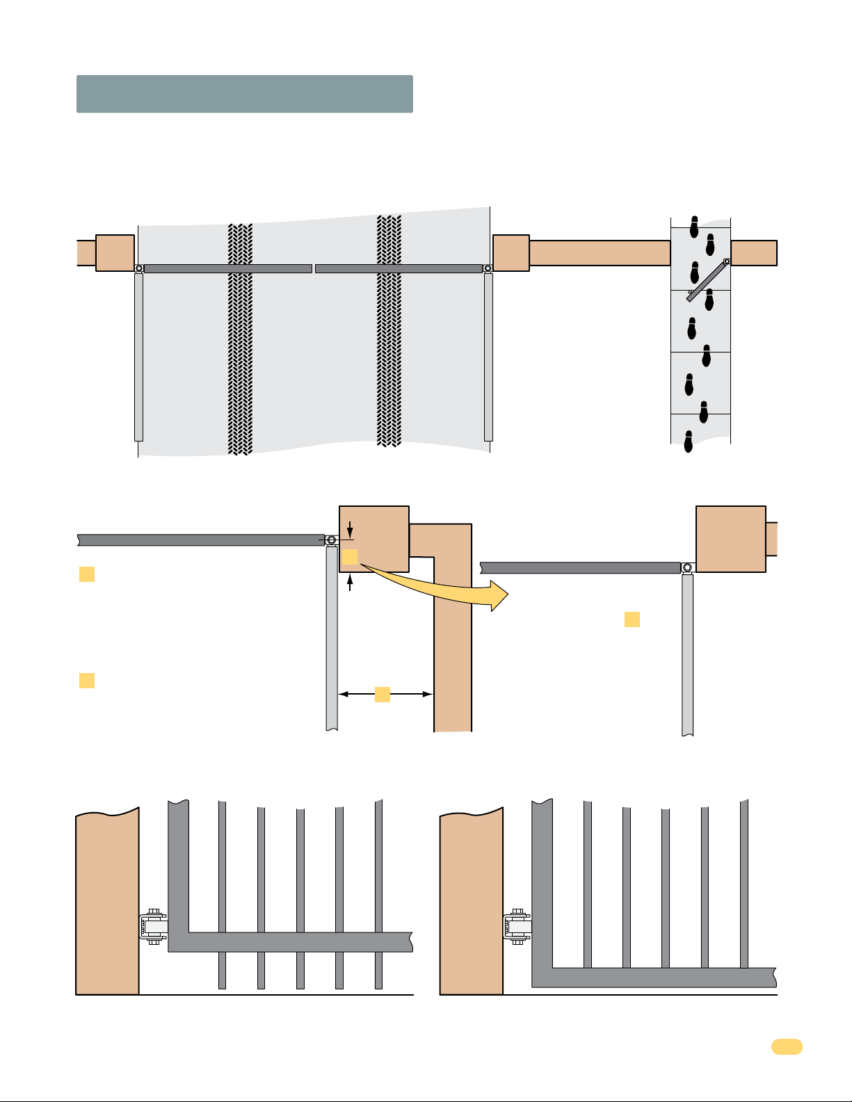
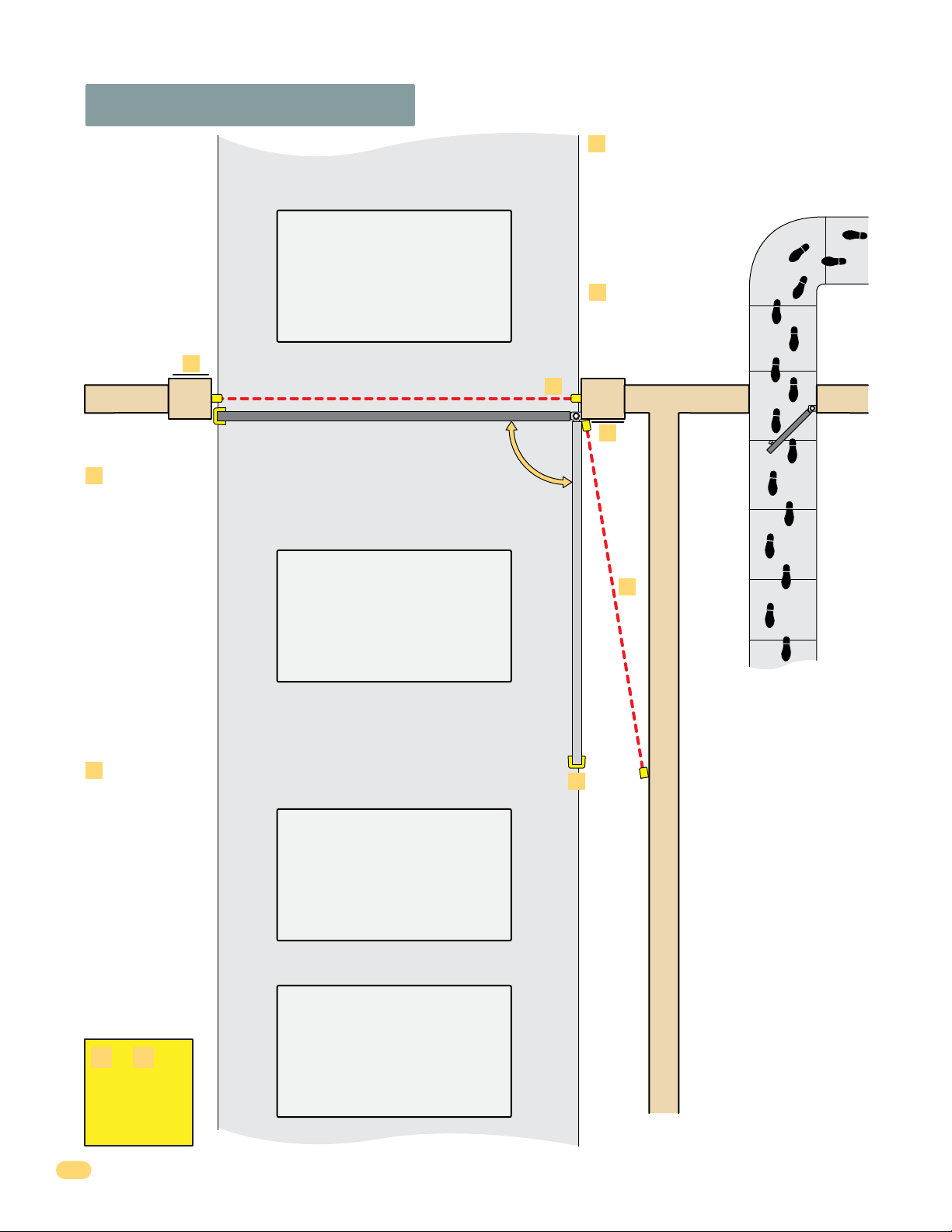
Swing Gate Requirements
The operator is intended for installation only on gates used for vehicles. Pedestrians must be supplied with a separate
access opening. The pedestrian access opening shall be designed to promote pedestrian usage. Locate the gate such that
persons will not come in contact with the vehicular gate during the entire path of travel of the vehicular gate.
(ref. UL325 56.8.4.b)
Closed Gates
Closed Gate
If distance is greater than 4 inches,
A
entrapment protection for this area is
required. ASTM F2200 7.1.1.1
If distance is less than 16 inches,
B
entrapment protection in this area
is required. ASTM F2200 7.1.1.2
Not Allowed OK
A
B
Opened Gate
Closed Gate
With the hinge mounted on
the corner of the pilaster,
the entrapment area is
eliminated and protection
is NOT required for this
area.
A
Opened Gate
Gates shall have smooth bottom edges, with vertical bottom edged protrusions not exceeding 0.50 inches. ASTM F2200 4.3
4302-067-N-1-16
7
Swing Gate Protection
Reverse Loop
Minimizes the potential of the gate
closing when a vehicle is present.
Number and placement of loops is
dependent on the application.
D
E
Monitored
Non-contact
Sensor
Minimizes the
potential of the gate
striking vehicular or
other traffic that
loops cannot sense.
Monitored device
helps protect
against
entrapment when
needed.
F
Contact
Sensor
Minimizes the
potential of the gate
striking vehicular or
other traffic that
loops cannot sense.
Monitored device
helps protect
against
entrapment when
needed.
Shadow Loop
Provides a hold open command to
the operator(s) only if the gate(s)
are at the full open position.
Note: Not used for solar control
box installations.
Reverse Loop
Minimizes the potential of the gate
closing when a vehicle is present.
Number and placement of loops is
dependent on the application.
C
Standard
Non-contact Sensor
Minimizes the potential
of the gate closing on
vehicular or other traffic
that loops cannot sense.
D
Warning Signs
Permanently mounted
and easily visible from
either side of the gate.
C
D
E
F
Separate
Pedestrian
Walkway
Located so
pedestrians
cannot come in
contact with the
vehicular gate.
or is
E F
REQUIRED
for operator
to function.
8
Automatic Exit Loop
(Optional) will provide an open
command to the gate operator(s)
when a vehicle is exiting the
property.
4302-067-N-1-16
SECTION 1 - SOLAR PANEL INSTALLATION CONSIDERATIONS
1.1 Concerns BEFORE Installation
Correct positioning of the solar panel will determine the efficiency of the system. In general, the panel should be facing TRUE
SOUTH at a specific TILT ANGLE towards the sun using the information provided on the next page to achieve the highest
efficiency. Some re-adjustment of the panel might be necessary to over time to “Fine Tune” the systems efficiency. The solar
panel should be installed as close as possible to the control box in an area free and clear of ALL obstructions and shadows
during the ENTIRE day. Generally, If the solar panel does NOT cast a shadow by the sun, the batteries are NOT being charged.
• Trees / Buildings that do not block the solar panel from direct sunlight in the summer,
could block the panel during the winter. The sun’s path across the sky is lower during the winter
than in the summer. The shadows that do not obstruct the solar panel during the summer
months, will cast longer shadows in the winter, which could block the panel then.
• Wind can exert extreme pressure on the solar panel and support post. Make sure they are
securely fastened.
• Dust can accumulate on the panel over time. Cleaning the panel every so often is necessary to
keep the system operating at its highest efficiency.
• Snow may cover the panel during the winter. You may want to re-adjust the panel to a steeper
angle to allow the snow to slide off. Even then, the panel may still accumulate snow and need to
be manually cleaned off when necessary to keep the system functioning.
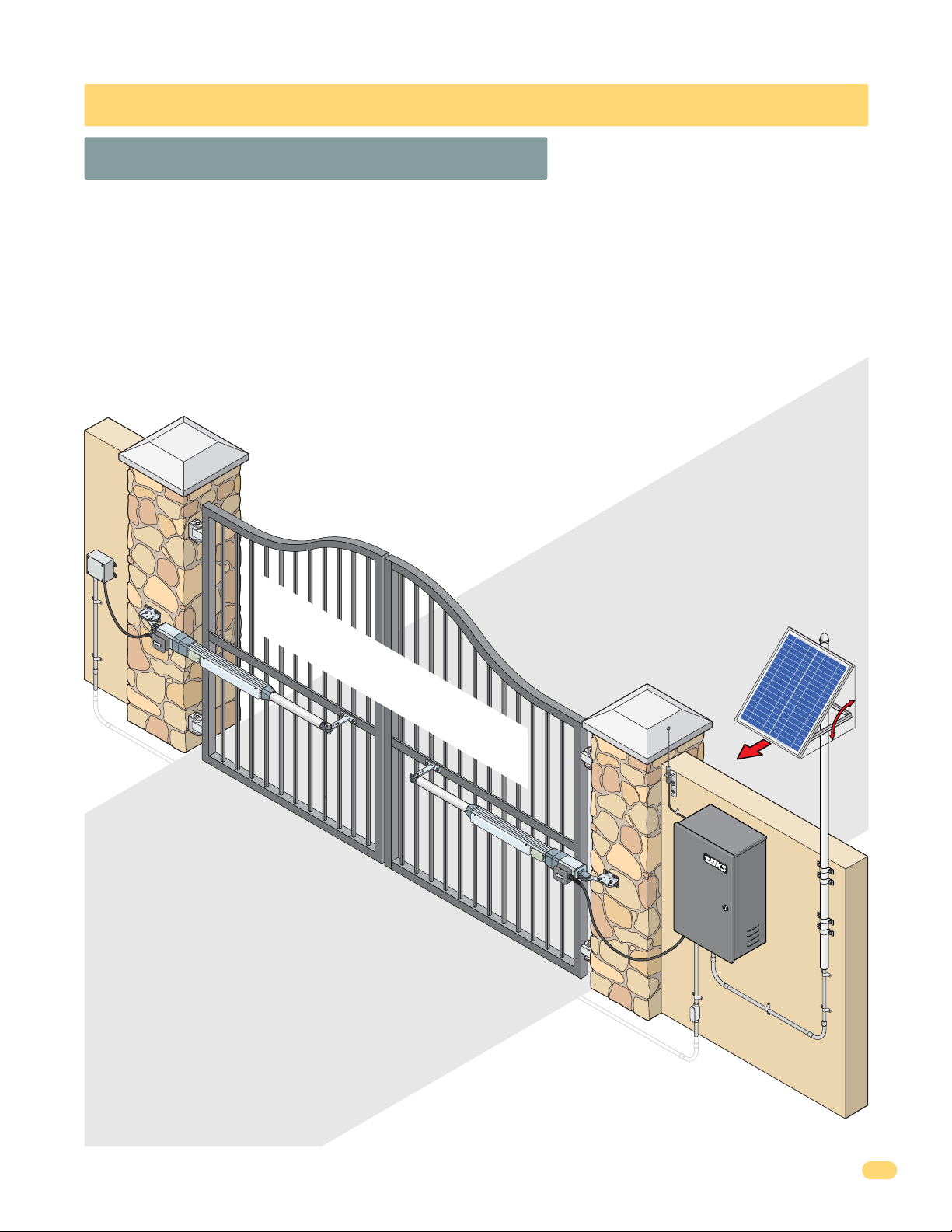
Sample Installation
Dual Gate Operators with 35 Amp/Hr Batteries
Mounting
Recommendations
The solar panel will perform MOST efficient when
installed as close as possible to the control box
(Within a couple of feet). Installation can be a maximum of
100 ft away from the box if necessary using a minimum 18
gauge wire run. Keep in mind, the efficiency of the solar panel will
diminish the farther away the panel is installed from the control box.
Solar Control Box Requirements:
• (1) ONE 24 Volt 10 Watt Solar Panel (P/N 2000-077) for 18 Amp/Hr Batteries.
• (1) ONE 24 Volt 20 Watt Solar Panel (P/N 2000-076) for 35 Amp/Hr Batteries.
True South
Tilt
Angle
4302-067-N-1-16
9
 Loading...