

DoorKing 2372-800 Operating Instructions Manual
DoorKing Part Number
9
6
3
0
OPER
WXYZ
TUV
PQRS
MNO
JKL
GHI
DEF
ABCSPSP
9
6
3
0
OPER
WXYZ
TUV
PQRS
MNO
JKL
GHI
DEF
ABCSPSP
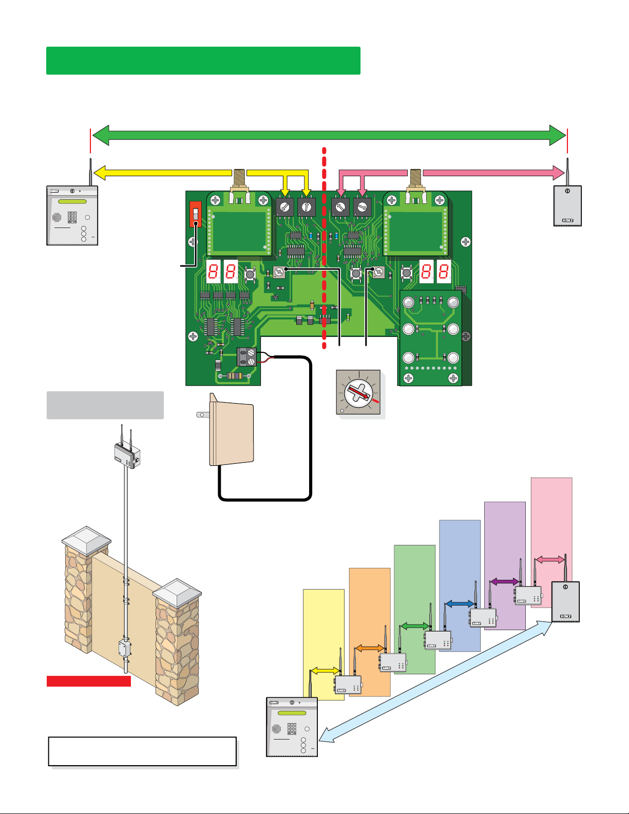
WIRELESS DUAL BAND REPEATER KIT
2372-080
The wireless dual band repeater kit (DBR) extends and expands the wireless communication range between an access control system and wireless
tracker expansion board or “tracker board”. It gets installed between the wireless devices that are too far or obstructed from each other to reliably
communicate with each other. It will receive a signal sent to it and repeat that signal to the next wireless device. Multiple DBRs can be used in the
same communication line of a tracker board. The signal range of a DBR is approximately 500 ft direct-line-of-sight with no signal interference.
500 ft
Base Side Remote Side
TELEPHONE ENTRY SYSTEM
OPERATING INSTRUCTIONS
1.
Use “A to Z” Buttons to Locate
Name and Code Number on Display.
Names are In Alphabetical Order.
T
o Call, Enter Code Number on
2.
Keypad or Press “Call” Button. If
Line is Busy, Press “#” or “Call” to
Hang Up. Try Again.
3.
E
nter on Open Display and Tone.
LOW PWR switch ON-Up Position,
board is put in a low power operating
mode where both LED signal displays
Base side communicates with the
wireless Baseboard of the 1830
series. The Channel and ID of the
Base side MUST match the Channel
and Net ID of the Baseboard.
DO NOT set Base side the same as
the Remote side.
Baseboard
DEF
ABC
11223
MNO
JKL
GHI
44556
WXYZ
TUV
PQRS
77889
OPER
0
Example:
HOLD TO SCAN
A
The wireless baseboard
Z
CALL
MUST be set to:
ID: E CH: 4
will turn OFF when not needed.
Installation
2361 Wireless
1/2” thick wall PVC
conduit recommended
(not supplied).
Metal conduit may
interfere with wireless
signal.
IMPORTANT:
Install the repeater
so the antenna is in a
location that is NOT
surrounded by metal
and is in free air as
high as possible above
the ground. Minimum
15 ft above ground
recommended.
LOW PWR
ON
4
3
2
1
0
F
E
D
BASE
SW1
12VDC INPUT
-
+
Power
Supply
12VDC
BASE
PROGRAM
Black - NEG
Red + POS
Rev “C”
or higher
Circuit
Board
BASE SIGNAL REMOTE SIGNAL
2372-011
5
6
7
8
9
A
B
C
BASE
RF RANGE
CHID CHID
4
5
3
2
1
0
F
E
D
C
BASE
PAIRED
4
4
5
5
3
REMOTE
PAIRED
3
6
6
2
2
7
E
D
C
8
9
A
B
REMOTE
REMOTE
PROGRAM
POWER
7
1
8
0
9
F
A
E
B
D
C
PAIRED
REMOTE
RF RANGE
REMOTE
SW5
1
0
F
D10D2
6
7
8
9
A
B
RF Range:
Set as shown.
67
62
72
58
52
50
76
84
85 MAX setting
FarNear
Cascading Dual Band Repeaters
Up to 5 Dual Band Repeaters (DBR) can be used in a cascade format to extend
Power Transformer
18 GA. Wire 100 ft max
16 GA. Wire 200 ft max
Wire Polarity Matters!
Note: Rev “B” circuit board uses 5VDC.
signal distance. The Base Side of 2nd DBR MUST match the Channel and ID of
the Remote Side from the 1st DBR and so on.
Make sure the Channel and ID combinations are
UNIQUE for every DBR in the cascade.
Channels
ORANGE
YELLOW
Channels
match
and
IDs match
and both are
unique
in cascade
Channels
match
and
IDs match
and both are
unique
in cascade
IDs match
and both are
in cascade
2nd DBR
SW4
BASE REMOTE
RF STRENGTH
RF SYNC
RF LOST
2373-010
BLUE
Channels
GREEN
match
and
unique
match
IDs match
and both are
unique
in cascade
3rd DBR
2358 Wireless
Tracker Board
Example:
The wireless
tracker board
MUST be set to:
ID: 2 CH: 9
Remote side communicates with
the wireless Tracker board. The
Channel and ID of the Remote
side MUST match the Channel
and Net ID of the Tracker board.
DO NOT set Remote side the
same as the Base side.
PURPLE
Channels
match
and
IDs match
and
and both are
unique
in cascade
5th DBR
4th DBR
PINK
Channels
match
and
IDs match
and both are
unique
in cascade
Tracker
Important Antenna Note:
Antenna range WILL VARY
GREATLY depending on individual
setup: Antenna height above the ground, background signal
interference, physical obstructions (trees, buildings etc.).
Adverse weather (rain) CAN also affect antenna range.
Range testing is HIGHLY recommended
before FINAL installation.
TELEPHONE ENTRY SYSTEM
DEF
ABC
11223
MNO
JKL
GHI
44556
WXYZ
TUV
PQRS
77889
OPER
0
OPERATING INSTRUCTIONS
1.
Use “A to Z” Buttons to Locate
Name and Code Number on Display.
Names are In Alphabetical Order.
T
o Call, Enter Code Number on
2.
Keypad or Press “Call” Button. If
Line is Busy, Press “#” or “Call” to
Hang Up. Try Again.
3.
E
nter on Open Display and Tone.
Baseboard
HOLD TO SCAN
1st DBR
cascade
Note: DoorKing offers a Wireless Test Range
Kit (P/N 1514-130) to allow easy testing of
the wireless signal between 2 devices at
chosen locations BEFORE installation of the
A
Z
CALL
devices. The self-powered test kit measures
the wireless signal between 2 devices in ANY
chosen locations. Ensuring that a good signal
can be achieved before installation occurs.
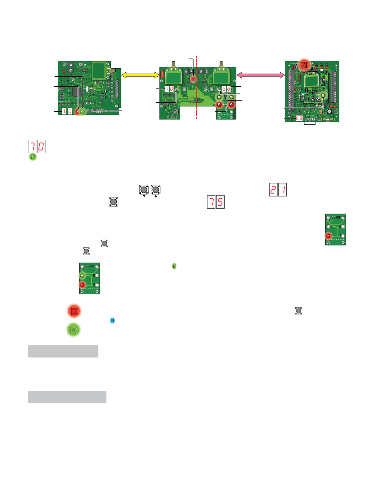
Automatic UNpaired Communication
R
R
RRR
TTR
Powering up boards will automatically establish communication between them and the baseboard. RF STAT/BASE & REMOTE PAIRED/RF SECURE LEDs will remain
RED on the boards which indicates the boards are communicating with each other, but UNPAIRED. This means that card codes/entry codes/remote codes will be
accepted from ANY tracker board that is set to the same channel and ID setting. See below to PAIR boards if desired.
8
9
7
A
RF RANGE
6
B
5
RESET
CH
C
4
D
3
E
2
F
1
0
PAIRED
8
9
7
A
NET
6
B
5
C
ON
4
D
ID
3
E
2
F
1
0
OFF
SYNC LOST
RCVD
SYNC REVD
ALLOW
RF STRENGTH
RF STAT
ONLY red when
it sees unpaired
tracker board.
LED Display
DISPLAY
OFF/ON
HEARTBEAT
DENY
STATUS
PROG
RF
STAT
STRENGTH
2361 Wireless Baseboard
LED Signal Indicators
DOORKING
2363-010
14
13
12
11
6
LED Base Display
5
4
3
2
1
PAIR
RLY 1 RLY 2
DOORKING
2361-010
PAIR
PROGRAM
BASE PAIRED (D2)
CHID CHID
4
4
4
5
3
6
2
7
1
8
0
9
F
A
E
B
D
4
5
5
3
3
6
2
2
7
1
1
8
0
0
9
F
F
A
E
E
B
D
D
C
C
REMOTE
D10
REMOTE
PAIRED
REMOTE
PROGRAM
POWER
RF SYNC
6
7
8
9
A
B
PAIRED
REMOTE
SW4
REMOTE
RF LOST
2373-010
5
3
6
2
7
1
8
0
9
F
A
E
B
D
C
BASE
SW1
BASE
RF RANGE
BASE
(SW1)
LOW PWR
ON
2372-011
BASE SIGNAL
12VDC INPUT
+
BASE
PROGRAM
2372 Wireless Dual Repeater Board
LED Remote Display
PAIRED REMOTE (SW4)
RF STRENGTH
RF STRENGTH
LED Display
2358 Wireless Tracker Board
1
2
3
4
5
6
7
8
9
10
11
12
13
14
15
16
17
18
19
20
LED displays on boards will indicate the signal loss between the boards. A smaller number is a stronger signal. 75 or lower is recommended.
RF STRENGTH LED should be GREEN on each board. YELLOW is marginal strength, RED is poor strength.
2361 Baseboard: LED Display shows the RF Range setting of the baseboard for 2 sec then shows signal loss that the board is actually receiving from 2372 Base side.
2372 Dual Repeater Board: Has LED displays for EACH side of the repeater which shows signal loss for Base and Remote sides.
2358 Tracker Board:
To Display RF Signal Loss
• Use UP and Down Arrow Buttons to select programming Step 21 shown on LED display.
RF SECURE
ON
7
1
6
5
4
3
0
RF RANGE
RF ID
PROGRAM
1489-010
Program Buttons
OUTPUT
ALARM
AUX
CODE
RELAY
RELAY
RELAY
2358-010
BAD
NC
NC
NC
NO
NO
NO
21
22
23
24
25
26
27
28
RF
29
30
31
4
5
3
3
6
2
2
7
1
1
8
0
0
9
F
F
A
E
E
B
D
D
C
ENT
32
A
33
B
C
34
RESET
• Press ENT Button to show Signal Loss number on LED display.
75 or lower is recommended.
ENT
BASE REMOTE
RF STRENGTH
Pairing Boards Together
When boards are PAIRED: Only card codes/entry codes/remote codes from paired tracker boards will be accepted.
Base Side of 2372: To pair the 2372 Base side with a 2361 Baseboard, the 2372 base side MUST be in an UNPAIRED mode:
RF LOST
Depress the BASE PROGRAM button (SW1) on the 2372 base side for few seconds until the RF LOST LED blinks rapidly and then turns steady RED.
Then press the PAIR button on the 2361 baseboard for few seconds to PAIR with the 2372 BASE side ONLY. Once the 2372 Base side receives a pairing
command from the 2361 baseboard, the middle green LED (RF SYNC) and the bottom red LED (RF LOST) blink rapidly; this indicates it has successfully been paired
with the 2361 Baseboard. The BASE PAIRED LED turns green (D2) and will stay lit on 2372 Base side.
RF SYNC
RF LOST
Remote Side of 2372: To pair the 2372 Remote side with the wireless tracker board, unpaired communication must have already been established between the 2.
The RF SECURE LED will remain ON steady red on top of 2358 tracker board. Press the 2372 Remote side PAIRED REMOTE button (SW4) for 3 seconds or
until the 2372 REMOTE PAIRED Blue LED (D10) blinks rapidly. Once 2358 tracker board has been successfully paired to Remote side of 2372,
the RF SECURE LED will turn green and remain lit on 2358 tracker board.
RF
SECURE
RF
SECURE
BASE REMOTE
RF STRENGTH
RF SYNC
RF LOST
2373-010
DoorKing Technical Support: 1-800-826-7493
RF SYNC
RF LOST
2373-010
Important Notice
Due to the nature of wireless communications, transmission and reception of data can never be guaranteed. Data may be delayed, corrupted (i.e., have errors) or be
totally lost. Although significant delays or losses of data are rare when wireless devices are used in a normal manner with a well-constructed network, DoorKing
wireless products should not be used in situations where failure to transmit or receive data could result in damage of any kind to the user or any other party,
including but not limited to personal injury, death, or loss of property. DoorKing, Inc. accepts no responsibility for damages of any kind resulting from delays or
errors in data transmitted or received using DoorKing wireless products, or for failure of DoorKing wireless products to transmit or receive such data.
Safety and Hazards
Do not operate DoorKing wireless products in areas where cellular modems are not advised without proper device certifications. These areas include environments
where cellular radio can interfere such as explosive atmospheres, medical equipment, or any other equipment which may
be susceptible to any form of radio interference. DoorKing wireless products can transmit signals that could interfere with this equipment. Do not operate DoorKing
wireless products in any aircraft, whether the aircraft is on the ground or in flight. In aircraft, DoorKing wireless products MUST BE POWERED OFF. When operating,
DoorKing wireless products can transmit signals that could interfere with various onboard systems.
Note: Some airlines may permit the use of cellular phones while the aircraft is on the ground and the door is open. DoorKing wireless products may be used at this
time.
The driver or operator of any vehicle should not operate DoorKing wireless products while in control of a moving vehicle. Doing so will detract from the driver or
operator’s control and operation of that vehicle. In some states and provinces, operating such communications devices while in control of a vehicle is an offence.
 Loading...