

DoorKing 2348 User Manual

Owner’s Manual
Model 2348 Elevator Control Boards
DoorKing, Inc.
120 Glasgow Avenue
Inglewood, California 90301
U.S.A.
Phone: 310-645-0023
Fax: 310-641-1586
www.doorking.com
P/N 2348-065 REV E, 10/11
Copyright 2001 DoorKing, Inc. All rights reserved.

Page 2 2348-065-E-10-11

Use this manual with the following models only.
Elevator Control boards 2348-010 Rev A or higher.
DoorKing, Inc. reserves the right to make changes in the products described in this manual
without notice and without obligation of DoorKing, Inc. to notify any persons of any such revisions
or changes. Additionally, DoorKing, Inc. makes no representations or warranties with respect to
this manual. This manual is copyrighted, all rights reserved. No portion of this manual may be
copied, reproduced, translated, or reduced to any electronic medium without prior written consent
from DoorKing, Inc.
Wiring charts on pages 38-51 may be copied as necessary.
2348-065-E-10-11 Page 3

Page 4 2348-065-E-10-11

Table of Contents
Section 1 – Introduction
1.1 General Information..................................................................................................................................7
1.2 Visitor Elevator Control
1.2.1 Lobby Hall Up Call On..............................................................................................................8
1.2.2 Lobby Hall Up Call Off..............................................................................................................8
1.3 Resident Elevator Control ........................................................................................................................9
1.3.1 Programming Resident Floor Control Relay Time ...................................................................9
1.4 System Requirements..............................................................................................................................10
Section 2 –Control Cabinet Installation
General Information..................................................................................................................................................11
2.1 Large Housing..........................................................................................................................................12
2.2 Small Housing..........................................................................................................................................13
Section 3 – Set-up Information
3.1 Block Diagram..........................................................................................................................................15
3.2 Board Set-up ............................................................................................................................................16
3.2.1 Elevator Shaft Identification .....................................................................................................16
3.2.2 Floor Identification....................................................................................................................16
3.2.3 Relay Settings..........................................................................................................................17
3.2.4 Lobby Hall Up Call Relay .........................................................................................................17
3.3 Switch Settings & Description ..................................................................................................................18
Section 4 – Wiring Information
4.1 General Information..................................................................................................................................19
4.2 Control Board Terminal Identification.......................................................................................................20
4.3 Power Wiring Block Diagram....................................................................................................................22
4.4 Control Wiring
4.4.1 Wiegand Wiring........................................................................................................................23
4.4.2 Floor Control Relay Wiring.......................................................................................................23
4.4.3 Lobby Hall Up Call Relay .........................................................................................................24
4.4.4 Ground Floor Detect Switch.....................................................................................................24
4.4.5 Resident Access Device ..........................................................................................................24
Wiring Diagram.........................................................................................................................................................25
Detail Wiring Diagram...............................................................................................................................................26
Section 5 – Elevator Control
Common Oversights.................................................................................................................................................27
Software Programming.............................................................................................................................................28
Section 6 – Trouble Shooting
6.1 General Trouble Shooting ........................................................................................................................35
6.2 Programming Trouble Shooting Aids
6.2.1 Automatic Test #1 ....................................................................................................................36
6.2.2 Manual Test # 2 .......................................................................................................................36
6.3 Appendix...................................................................................................................................................37
Relay Wiring Identification Sheets............................................................................................................38
2348-065-E-10-11 Page 5

Page 6 2348-065-E-10-11
Section 1 – Introduction
DoorKing's Model 2348-010 Elevator Control System provides complete elevator security and is used
to (1) restrict which floors visitors may have access to via the elevator(s) after they have been granted
access by a building resident, and (2) restrict which floors residents may have access to via the
elevator(s). Elevator control is typically used in high rise apartment building applications that are
equipped with this option and a DoorKing Model 1833, 1835 or 1837 Telephone Entry System, or the
DoorKing Model 1838 Multi-door Access Control System. This system also requires the installation of
an access device (card reader) in the elevator car to enable building residents to activate the floor
buttons according to the security level assigned to them.
1.1 General Information
Up to eight (8) elevators may be controlled by up to eight (8) DoorKing Access Control Systems
(1833, 1835, 1837, 1838) at four (4) entrances. Typically, a telephone entry system is installed at the
building entrance. The 2348-010 elevator control board(s) is located and installed close to the
elevator electronic control panel. A three conductor wire connects the 2348-010 board to the
telephone entry system. Resident access to different floors in the building is controlled by an access
device (card reader) installed in the elevator car and connected to the telephone entry system (or to a
Tracker expansion board) by routing the wiring along with the elevator car ele ctrical umbilical cable.
The elevator control system is able to restrict elevator button operation by interrupting the button
wiring between the elevator car and the elevator control electronics. The elevator car floor button
wiring is routed through the relays on the elevator control board before being connected to the
elevator electronics. In this manner, the 2348-010 elevator control system may either open or close
the wiring to the floor buttons in the elevator car upon command, and thus either disable or enable the
desired floor button(s) for a programmed period of time.
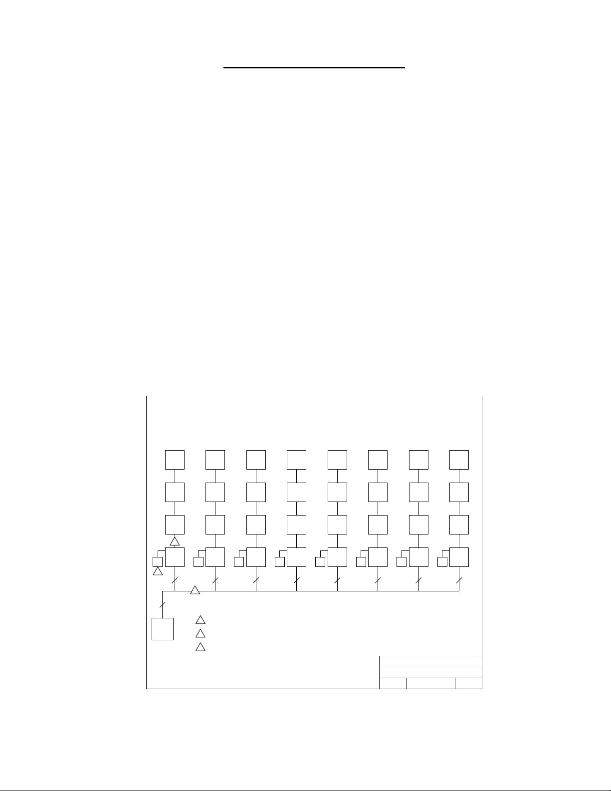
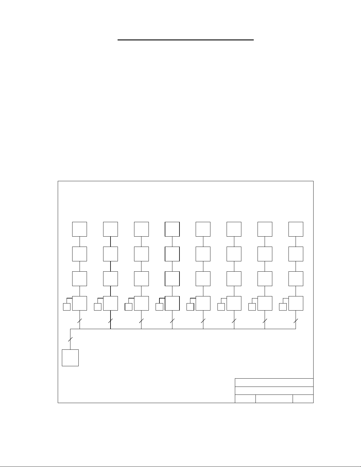
Elevator Control Block Diagram
Elevator
Shaft 1
Relays
49-64
Relays
33-48
Relays
17-32
3
MASTER
Board 1
Relays
PWR
1-16
2
3 3 3 3 3 3 3 3
3
1833, 1835,
1837, 1838
Access
Control
System
Elevator
Shaft 2
Relays
49-64
Relays
33-48
Relays
17-32
MASTER
Board 1
Relays
PWR
1-16
1
3 conductor, stranded with overall shield, 18, 20, 22 or 24 gauge is sufficient for these connections.
1
16 VAC Power. One transformer for each four (4) Elevator Boards.
2
Supplied ribbon cable.
3
PWR
Elevator
Shaft 3
Relays
49-64
Relays
33-48
Relays
17-32
MASTER
Board 1
Relays
1-16
PWR
Elevator
Shaft 4
Relays
49-64
Relays
33-48
Relays
17-32
MASTER
Board 1
Relays
1-16
PWR
Elevator
Shaft 5
Relays
49-64
Relays
33-48
Relays
17-32
MASTER
Board 1
Relays
1-16
Elevator
Shaft 6
Relays
49-64
Relays
33-48
Relays
17-32
MASTER
Board 1
Relays
PWR
1-16
Title:
Date: Rev.Dwg. No.10/11 M2348-065-1
Elevator
Shaft 7
Relays
49-64
Relays
33-48
Relays
17-32
MASTER
Board 1
Relays
PWR
1-16
DOORKING, INC., INGLEWOOD, CA 90301
Elevator Control Block Diagram
Figure 1
PWR
Elevator
Shaft 8
Relays
49-64
Relays
33-48
Relays
17-32
MASTER
Board 1
Relays
1-16
C
2348-065-E-10-11 Page 7

1.2 Visitor Elevator Control
When a visitor calls a resident via the telephone entry system and the resident grants the visitor
access, data is sent from the telephone entry system to the 2348-010 elevator control board. Upon
receiving this data, the elevator control board will respond in two different manners depending on the
setting of SW2, switch 8.
1.2.1 Lobby Hall Call On
If SW2, switch 8 is in the OFF position, a "Lobby Hall Up Call" relay on the elevator control board will
activate and call the elevator to go to the lobby or ground floor. This is accomplished by wiring the
output of the lobby call relay in parallel to the ground floor button in the elevator electronics panel.
Once the elevator reaches the ground floor, a ground floor detect switch must signal the 2348-010
board that the elevator has arrived. This signal is in the form of a switch closure across terminals 17
and 18 and may be available from existing hardware in the elevator electronics panel. Once the
2348-010 board receives this elevator detect signal, the floor button that the resident who granted the
visitor access resides on, will become "live" for a period of time that has been set in the DoorKing
Remote Account Manager software. Only this floor button will work when the visitor enters the
elevator.
Using the lobby hall call feature is desirable in that the timer for the floor button does not become
active until the elevator reaches the lobby or ground floor. For example, if the timer was set in the
software to activate the floor button for one minute, the one minute timer will not start until the
elevator car reaches the ground floor. This would assure that there is ample time for the visitor to
walk to the elevator and press the respective floor button.
1.2.2 Lobby Hall Call Off
If SW2, switch 8 is in the ON position, the "Lobby Hall Up Call" relay on the 2348-010 board does not
operate. When the visitor is granted access, the floor button that the resident who granted the visitor
access resides on immediately becomes "live" for the period of time that has been programmed in the
software. In this mode, the 2348-010 board does not call the elevator to the lobby or ground floor.
This would require the visitor to press the elevator call button in the lobby to call the elevator to the
ground floor.
It is important to note that if the 2348-010 control board is used in this manner, the floor button in the
elevator car becomes "live" immediately after the visitor is granted access and the time period that
the button is "live" begins immediately. Because of this, the time period that the button is "live" must
be set for an adequate amount of time to allow the elevator to reach the ground floor from the highest
floor, and allow the visitor time to walk to the elevator. This time is set in the DoorKing Remote
Account Manager software.
Page 8 2348-065-E-10-11
1.3 Resident Elevator Control
When elevator control is in use, an access device such as a card reader must be installed in the
elevator car to allow residents access to the floors in the building. Residents can be restricted to
certain floors, or allowed access to all floors. These restrictions are dependent on the security level
assigned to the resident and are programmed in the DoorKing Remote Account Manager software.
When a resident enters the elevator car, they insert their access card into the card reader. This is
necessary because the floor buttons in the elevator remain "dead" until a command is received by the
2348-010 board to turn them on. Depending on the security level assigned to them, the floor
button(s) in the elevator car will become "live.”
The time interval that the button(s) is “live” is dependant on the revision level of the 1830 series
telephone entry/access controller circuit board, not the 2348 elevator control board. Refer to the
table below.
Controller Circuit Board Revision Level Time Interval
1833
1835
1837
1833
1835
1837
1838 A - C 7 Seconds
1838 D - Higher
A - E
F - Higher
7 Seconds
Programmable from 1 to 254
seconds
Programmable from 1 to 254
seconds
Table 1
1.3.1 Programming Resident Floor Control Relay Time
The following programming sequence can only be performed at the telephone entry / access system
controller keypad. The resident elevator button relay time interval cannot be programmed via the
Remote Account Manager software. The maximum time that can be entered is 254 seconds.
Factory setting = 007
1. Press * 3 6 and then enter the four digit master code _ _ _ _ (beep). The display on the
1835 and 1837 systems will read: RES ELE TIME xxx SEC
2. Enter the relay time in seconds (001 – 254) _ _ _ then press * (beep).
3. Press 0 # together to end this programming sequence (beeeeeep).
2348-065-E-10-11 Page 9

1.4 System Requirements
The maximum number of elevator control systems that can be controlled from a DoorKing access
control system (1833, 1835, 1837, 1838) is eight. That is eight elevator cars (shafts) with each car
serving up to 64 floors. Each 2348-010 elevator control board can control up to 16 floors in a single
shaft, therefore a single elevator serving 64 floors requires the use of four (4) 2348-010 boards. If
two elevator cars (shafts) need to be controlled, with each car serving 32 floors, a total of four (4)
2348-010 boards would be required - two for each elevator car (shaft).
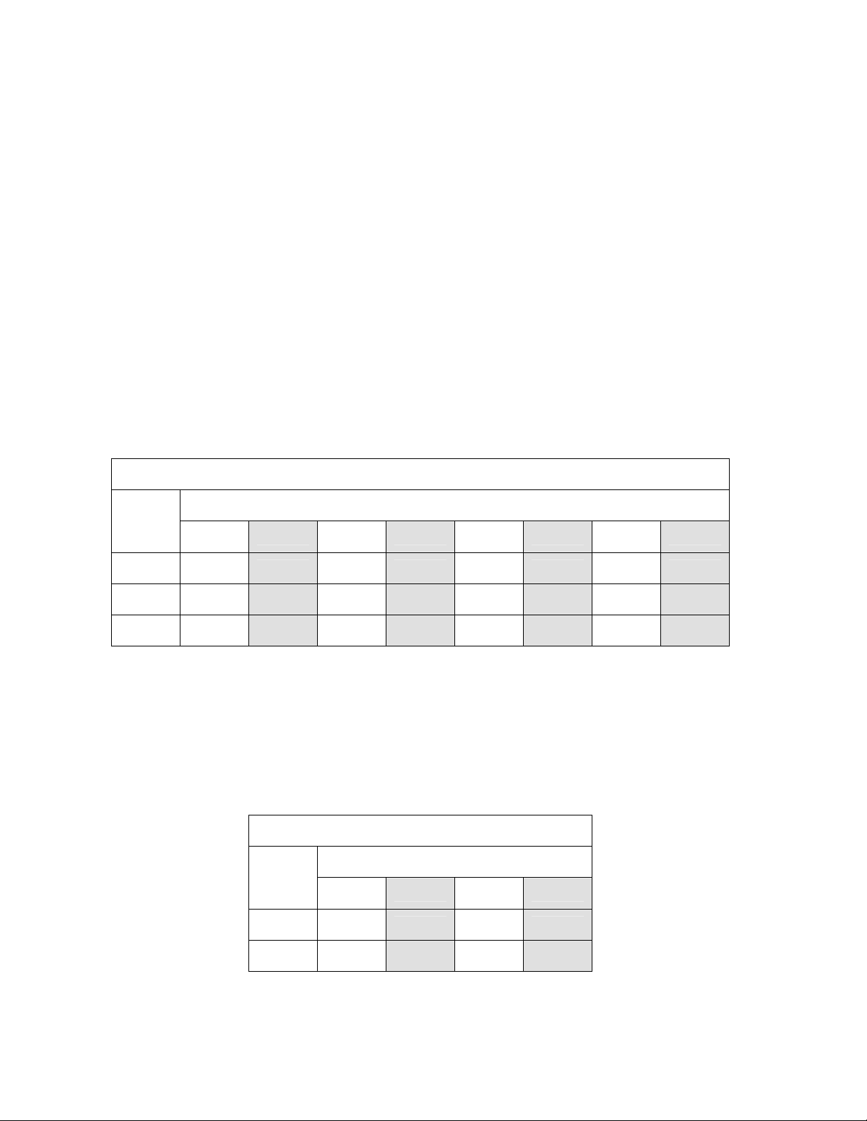
The table below determines the number of 2348-010 boards required to control the elevator system,
depending on the number of cars (shafts) and floors that are to be serviced.
Elevator Shafts
Floors
Car 1 Car 2 Car 3 Car 4 Car 5 Car 6 Car 7 Car 8
1-16
17-32
33-48
49-64
1 2 3 4 5 6 7 8
2 4 6 8 10 12 14 16
3 6 9 12 15 18 21 24
4 8 12 16 20 24 28 32
Table 2
The 2348-010 boards are housed in either a small (1816-102) or large (1816-100) cabinet. The small
cabinet will hold two 2348-010 boards, while the large cabinet will hold up to four boards. Each
elevator shaft requires either a small or large cabinet depending on the number of 2348 boards that
are required for the shaft.
The DoorKing elevator control system can only be used with a DoorKing model 1833, 1835 or 1837
telephone entry system, or with the DoorKing model 1838 multi-door access control system. A card
reader (or other access device) must be installed in the elevator car to allow building residents access
to floors as defined within the security level assigned to them. The system must be programmed with
a PC using the DoorKing Remote Account Manager for Windows software, version 5.0 or later.
Tracker expansion boards may be required depending on the number of doors and elevator cars
being controlled by the system.
Page 10 2348-065-E-10-11

Section 2 - Control Cabinet Installation
Installation of the 2348-010 elevator control board(s) and cabinet(s) should be coordinated with the
elevator service company. The cabinets should be installed in close proximity to the elevator
electronic control panel so that wiring between the elevator electronic control panel and the 2348-010
board(s) is simplified. 110 VAC power must be available nearby to power the transformer(s) that will
supply 16 VAC power to the 2348-010 board(s). One 16 VAC power transformer is required for each
elevator car (shaft) controlled.
1. Open the cabinet and remove any ribbon cables from the 2348-010 board (systems with
two or more boards only).
2. Remove the four screws from each corner of the board and then remove the board from
the cabinet. CAUTION: Touch a proper ground with your hands before removing
the board(s) from the cabinet. This will discharge any static electricity and prevent
electrostatic discharge damage to the board.
3. Mount the cabinets. Each cabinet has four mounting holes located in the corners. Be
sure that the mounting screws do not protrude into the cabinet in such a way that they
can cause a short to the back of the 2348-010 board.
4. Make any conduit connections at this time.
5. Clean out the cabinet being sure that any metal shavings are removed from the cabinet.
6. Re-install the 2348-010 board(s) and the ribbon cables.
2348-065-E-10-11 Page 11
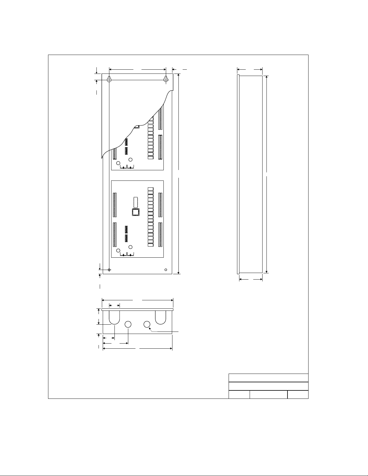
2.1 Large Housing
FOUR BOARD ENCLOSURE
.875
10.25 .875
4.125
35.25
35
.675
2.0
2.5
2.0
4.625
1.625
12.375
.875 DIA 2 PL
12
Title:
Date: Rev.Dwg. No.
4.0
DOORKING, INC., INGLEWOOD, CA 90301
Quad Enclosure for 2348-010 Boar d
P/N 2348-081
10/03 M2348-065-2
A
Figure 2
Page 12 2348-065-E-10-11
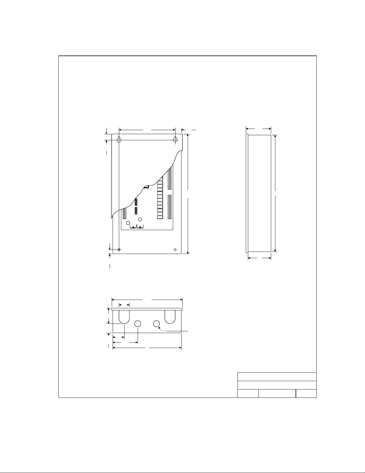
2.2 Small Housing
TWO BOARD ENCLOSURE
10.25 .875
.875
21.25
.675
12.375
2.0
4.125
21
4.0
2.5
.875 DIA 2 PL
2.0
4.625
1.625
12
DOORKING, INC., INGLEWOOD, CA 90301
Dual Enclosure for 2348-010 Board
Title:
P/N 2348-080
Date: Rev.Dwg. No.
10/03 M2348-065-3
A
Figure 3
2348-065-E-10-11 Page 13

Page 14 2348-065-E-10-11
Section 3 – Set-up Information
This chapter will describe how to set-up the 2348-010 elevator control board for different modes of
operation, and how to identify each board and which elevator and floors the board is controlling to the
access system. This is determined by the switch settings of SW1 (top) and SW2 (bottom) on each of
the 2348-010 boards. The floor relays on the board can be set to operate as either normally closed
or normally open devices by placement of the relay jumpers on either the N.O. or N.C. pins next to
the corresponding relay.
3.1 Block Diagram
Each elevator control board has 16 floor relays. One elevator shaft can consist of four (4) 2348-010
elevator boards to control up to 64 floors (16 x 4). The elevator boards are connected to each other
via a ribbon cable. The elevator board that is connected directly to the access system is designated
as the MASTER board - therefore each MASTER board can have up to three (3) additional 2348-010
boards connected to it via the ribbon cable. Each access system (1833, 1835, 1837, 1838) can have
up to eight (8) MASTER 2348-010 boards connected to it, with each master controlling an additional
three (3) boards. Therefore, the access system can accommodate up to eight (8) elevator shafts with
each shaft accommodating up to 64 floors.
Elevator Control Block Diagram
Elevator
Shaft 1
Relays
49-64
Relays
33-48
Relays
17-32
MASTER
Board 1
Relays
PWR
1-16
3 3 3 3 3 3 3 3
3
1833, 1835,
1837, 1838
Access
Control
System
PWR
Elevator
Shaft 2
Relays
49-64
Relays
33-48
Relays
17-32
MASTER
Board 1
Relays
1-16
PWR
Elevator
Shaft 3
Relays
49-64
Relays
33-48
Relays
17-32
MASTER
Board 1
Relays
1-16
PWR
Elevator
Shaft 4
Relays
49-64
Relays
33-48
Relays
17-32
MASTER
Board 1
Relays
1-16
PWR
Elevator
Shaft 5
Relays
49-64
Relays
33-48
Relays
17-32
MASTER
Board 1
Relays
1-16
Elevator
Shaft 6
Relays
49-64
Relays
33-48
Relays
17-32
MASTER
Board 1
Relays
PWR
1-16
DOORKING, INC., INGLEWOOD, CA 90301
Elevator Control Block Diagram
Title:
Date: Rev.Dwg. No.12/07 M2348-065-4
PWR
Elevator
Shaft 7
Relays
49-64
Relays
33-48
Relays
17-32
MASTER
Board 1
Relays
1-16
Figure 4
PWR
Elevator
Shaft 8
Relays
49-64
Relays
33-48
Relays
17-32
MASTER
Board 1
Relays
1-16
B
2348-065-E-10-11 Page 15
3.2 Board Set-up
The 2348-010 elevator boards must be set to identify to the access control system which elevator
shaft that it is in, and which floors in the elevator shaft that it is controlling. This programming function
is accomplished by the two DIP switches on the elevator control board, with each DIP switch having
eight (8) switches in them. The top switch is designated as SW-1 and the bottom switch is
designated as SW-2. NOTE: Switches 4-7 on SW-1 and switches 3-7 on SW-2 are spares and
are not used. Leave these switches in the OFF position.
3.2.1 Elevator Shaft Identification
Each MASTER board must be set to identify which elevator shaft that it is controlling (shaft 1, 2, 3, 4,
5, 6, 7 or 8). The shaft setting is set by switch SW-1, switches 1, 2 and 3 (Table 3). The MASTER
board is the board that has 16 VAC power connected to it and is connected to the access control
system elevator terminals and receives weigand data from the access control system. There can
only be one MASTER board per shaft. If there is more than one MASTER board in the system (two
or more elevator shafts), it is very important that these switches be set correctly.
NOTE: SW-1, switches 1, 2 and 3, apply only to the MASTER board. These switches are not
relevant to other 2348-010 boards connected to the MASTER board via the ribbon cable and can be
left in the OFF position.
Master Board Identification SW-1 Switch Settings
Elevator Shaft Number
SW-1
2 3 4 5 6 7 8
Switch 1
Switch 2
Switch 3
1
OFF ON OFF ON OFF ON OFF ON
OFF OFF ON ON OFF OFF ON ON
OFF OFF OFF OFF ON ON ON ON
Table 3
3.2.2 Floor Identification
Each of the 2348-010 elevator control boards connected to the system must be set to identify which
floors that the board will control in the shaft that it is in. The floor setting is set by switch SW-2,
switches 1 and 2 (Table 4.).
Floor Identification SW-2 Switch Settings
Floors
SW-2
1-16
17-32 33-48 49-64
Switch 1
Switch 2
OFF ON OFF ON
OFF OFF ON ON
Table 4
Page 16 2348-065-E-10-11
 Loading...