

DoorKing 1837, 1835 Owner's Manual
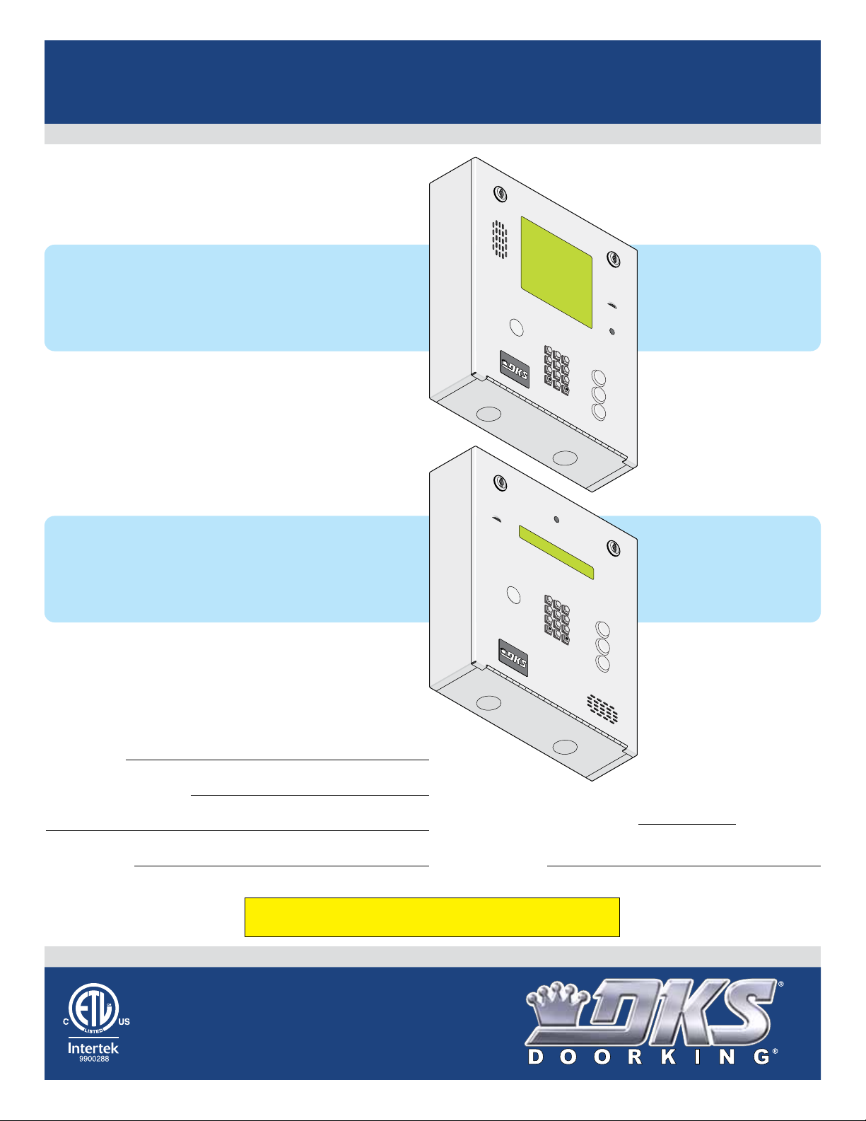
Installation/Owner’s Manual
90 Series
1837
1835
Telephone Entry and Access Control Systems
1837
1837
8 Line LCD Display
For 1837 circuit board:
1837-010 Revision Z or higher.
Ad
a
ms J
Akins M
An
n
e
se J
>Anderson
Ap
p
legate B
Aust
i
n D
Ba
l
s
baugh B
Bass
J
90 Series
90 Series
1835-067-A-9-18
26, 30 and 31-Bit Wiegand Compatible
020
H
115
3
52
>CALL
6
56
078
221
321
1
2
3
4
5
6
7
8
A
9
0
Z
CALL
1835
1835
Single Line LCD Display
For 1835 circuit board:
1835-009 Revision Z or higher.
Date Installed:
Installer/Company Name:
Phone Number:
Leave Manual with Owner
Ad
a
ms
J
0
20
1
2
3
4
5
6
7
8
9
0
A
Z
CALL
Model Number
Circuit Board
Serial Number
and Revision Letter:
Download REMOTE ACCOUNT MANAGER Software FREE at:
http://www.doorking.com/telephone/software
Copyright 2018 DoorKing®, Inc. All rights reserved.
Conforms To UL STD 294
Certified To CSA STD C22.2 # 205
Copyright 2009 DoorKing, Inc. All rights reserved.
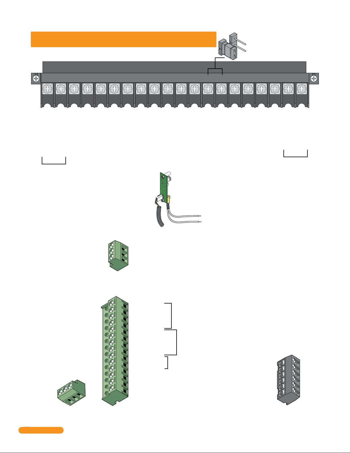
QUICK GUIDE: Terminal Descriptions
See section 2.3 for terminal wiring.
Main Terminal
NO
Relay 2 Note: Normally Open and
NC
Normally Closed relay jumper is
used to set Relay 2 input on the
circuit board (See section 4.6).
5VDCIMDSPKRCOMMICPSWCGNDPHONE
16AC16ACBAT1NO1NC1C2RY2CAZIMC
1234567891011121314151617181920
Phone Line Connection
1600 ft. max. with 22 AWG wire.
(Wiring MUST be twisted and completely isolated from the ground)
Earth Ground Only (See Section 2.1.3).
Phone Line Connection
800 ft. max. with 24 AWG wire.
Microphone Input.
Switch Input. A closure between terminals 4 and 6 will cause the designated relay(s) to activate for
the programmed strike time or dial a phone number – see 3.2.7. The Postal Switch is connected here.
Speaker Output.
Common for switch input #4, microphone,
speaker, AZ & CALL buttons and battery neg.
5 VDC Power for LED lighting.
(Not used).
“Z” Button Input.
(Not used).
Relay 2 Contact – 30 Volt, 3 Amp max.
Relay 2 Common – 30 Volt, 3 Amp max.
“A” Button Input.
Relay 1 Normally Open – 30 Volt, 3 Amp max.
Relay 1 Normally Closed – 30 Volt, 3 Amp max.
Relay 1 Common – 30 Volt, 3 Amp max.
Back-up Battery POSITIVE
For Phone System Only. (connect negative to terminal 6)
16 VAC Input Power
16 VAC Input Power
100 ft. max. with 18 AWG wire.
200 ft. max. with 16 AWG wire.
20 VA min. for 1835, 40 VA min. for 1837.
UL 294
Tamper
Switch
Note: Located under microphone
board (See Section 1.7).
Elevator Control
Terminal
Non-Removable
Note: Connect to the Elevator Control Board (2348-010).
See Elevator Control Board Manual 2348-065 for more info.
1
1 DATA 1 – Connect to terminal 20 of elevator control board.
2
2 DATA 0 – Connect to terminal 21 of elevator control board.
3
3 COMMON – Connect to terminal 22 of elevator control board.
2
Quick Guide - 1
Normally Open – 30 Volt, 3 Amp max.
Normally Closed – 30 Volt, 3 Amp max.
Common – 30 Volt, 3 Amp max.
C
NC
NO
Relay 0 Terminal
Non-Removable
Aux Terminal
Removable
14
14 +12 VDC Power.
13
13 Common.
12
12 DATA 1.
11
11 DATA 0.
10
10 +12 VDC Power.
9
9 Common.
8
8 DATA 1.
7
7 DATA 0.
6
6 16 VAC Output.
5
5 16 VAC Output.
4
4 Back-up Battery NEGATIVE (For Wiegand Only).
3
3 Back-up Battery POSITIVE (For Wiegand Only).
2
2 16.5 VAC Input Power – 20 VA.
1
1 16.5 VAC Input Power – 20 VA.
(Powers RS-232, elevator control and Wiegand)
Note: The 14-pin aux terminal can be removed for easy
wiring. Expansion boards are connected here when used.
See Expansion
26, 30 and 31 Bit
Wiegand input (Card Reader)
activates Relay 1 for
programmed strike time
26, 30 and 31 Bit
Wiegand input (Card Reader)
activates Relay 2 for
programmed strike time
For card readers that have additional
lighting for outdoor use.
Tracker Board
Manual
2358-065 and
section 2.3.2,
2.3.3 for more
information.
Transmit Data 1
Receive Data 2
Request to Send 3
Clear to Send 4
Signal Ground - Shell 5
Not used 6
Note: Located in the upper left corner of circuit
board. The 6-pin terminal can be removed for
easy wiring. Connects a PC (See Section 2.5.1).
RS-232
Terminal
Removable
1
2
3
4
5
6
1835-067-A-9-18
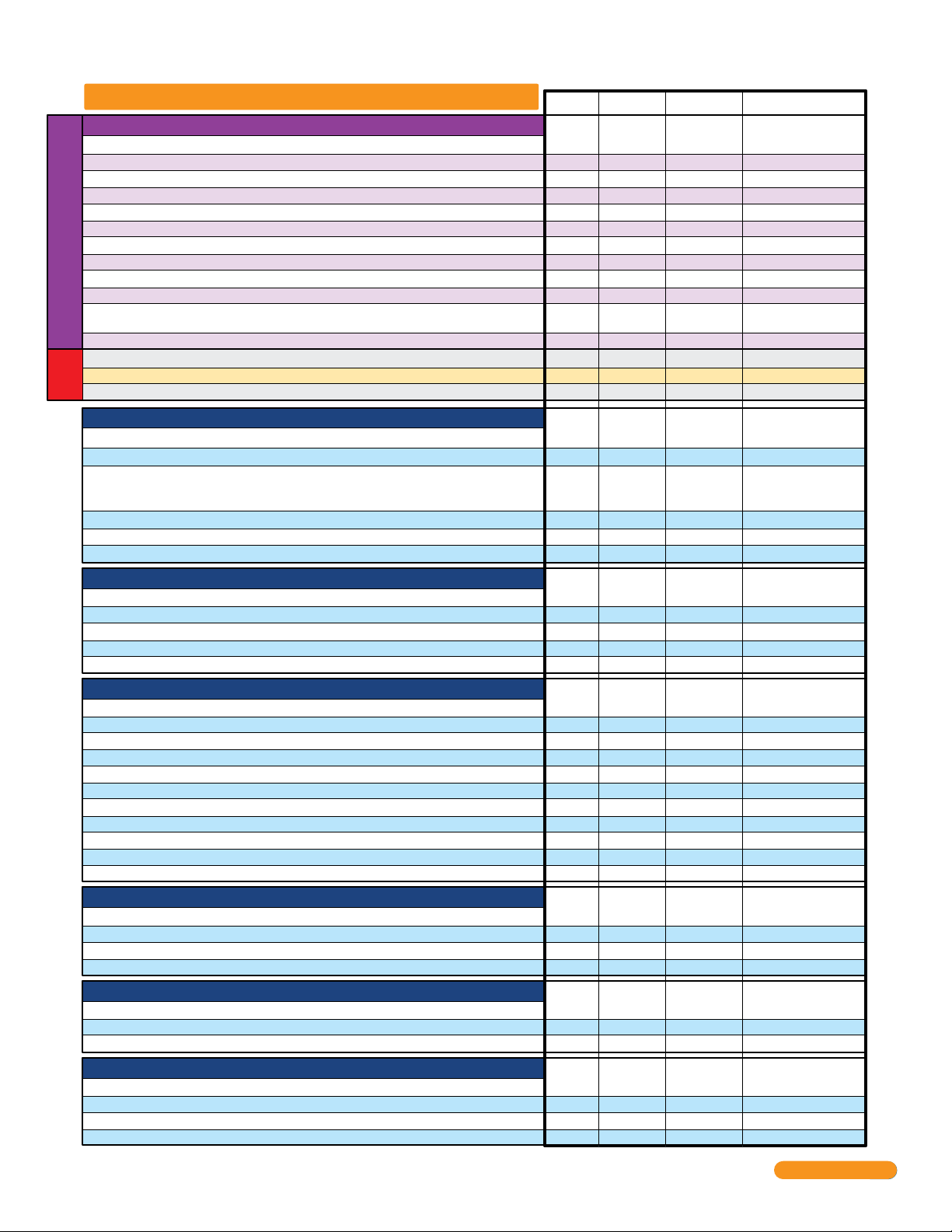
Overview for Entry System Keypad Programming
Section 3.2 Setup Entry System for PC Programming
Master Code - REQUIRED Programming
Number of Area Codes Allowed
Call-Up Operation, Interfacing with DKS 1816 or 1820 Systems Only
Resident Elevator Button Relay Time
Open Tone ON or OFF
RS-232 Speed Setting
Switch Input Feature
Elevator Control Feature
Single or Multiple Systems
DKS Data over IP Phone Number or System ID Number
Re-Program Memory Size, with/without Cards and Anti-Pass Back
(Only needed when New 1830 system is used with OLDER 1830 systems)
NOT Programmable from Software.
Program from System Keypad ONLY.
Live Transactions Viewing on a PC - ON or OFF
Display DKS Data over IP Phone Number or System ID Number
Test Connection to DKS Data over IP
over IP
Testing
DKS Data
Turn DKS Data over IP OFF or ON (Automatically ON after programming 3.2.10)
Section 3.3 General Programming using System Keypad
Relay Strike Time
Talk Time
Tone Open Numbers
Switch Input Relay(s) Activation
Touch-tone / Rotary-Dial
Rotary Dial-9 Relay(s) Activation
Section 3.4 Programming Letters, Numbers and Messages
Programming Letters and Numbers from Keypad
Programming the User Message - 1835 ONLY
Programming the Instruction Message - 1835 ONLY
Programming the User Message - 1837 ONLY
Programming the Instruction Message - 1837 ONLY
Section 3.5 Programming Phone Numbers and Names
Programming the Directory Code Length
Programming Directory Code AND 7-Digit Phone Numbers - No Area Code
Programming Area Codes
Programming Phone Numbers that need Area Codes
Programming Names
Deleting Individual Phone Numbers
Delete Names
Delete Area Codes
Display Phone Numbers
PBX Line Access Code Programming
Touch-Tone Dialing Pause
Section 3.6 Programming Device Codes
Programming Five-Digit Device Codes
Delete Device Codes
Enabling Facility Codes
Programming Facility Codes
Section 3.7 Programming Four-Digit Entry Codes
Programming Four-Digit Entry Codes
Delete Entry Codes
Entry Code Ranges
Section 3.8 Anti-Pass Back
Programming the Anti-Pass Back Mode
Re-Sync All Devices
Re-Sync Individual Devices
Reset Facility Counter
Page # Factory Setting
Section Command
26
27
27
27
27
28
28
28
28
29
29
59
59
59
32
32
33
33
34
34
35
36
37
38
39
41
41
42
42
43
43
43
44
44
44
44
45
45
45
45
46
46
46
47
47
47
47
3.2.1
3.2.2
3.2.3
3.2.4
3.2.5
3.2.6
3.2.7
3.2.8
3.2.9
3.2.10
3.2.11
3.2.12 OFF30
6.1.7
6.1.8
6.1.9
3.3.1
3.3.2
3.3.3
3.3.4
3.3.5
3.3.6
3.4.1
3.4.2
3.4.3
3.4.4
3.4.5
3.5.1
3.5.2
3.5.3
3.5.4
3.5.5
3.5.6
3.5.7
3.5.8
3.5.9
3.5.10
3.5.11
3.6.1
3.6.2
3.6.3
3.6.4
3.7.1
3.7.2
3.7.3
3.8.1
3.8.2
3.8.3
3.8.4
Master
Switch ON
60
*
78
*
36
*
15
*
85
*
18
*
75
*
04
*
59
*
95
*
19
*
56
*
29
*
55
*
03
*
08
*
05
*
50
*
07
*
51
*
None
80
*
81
*
80
*
81
*
20
*
01
*
24
*
41
*
66
*
01
*
65
*
24
*
06
*
09
*
27
*
70
*
71
*
72
*
73
*
02
*
02
*
12
*
43
*
45
*
46
*
48
*
No factory setting
1 (255 area codes)
0 (OFF)
007 (7 sec)
1 (tone ON)
1 (19200 Baud)
0 (activates relay)
1 (Turned ON)
Single system
Issued by DoorKing
8-3000 Memory
2-Card w/Anti-Pass Back
Testing Option
Testing Option
Testing Option OFF
Relay 0: 01 (1 sec)
Relay 1: 01 (1 sec)
Relay 2: 01 (1 sec)
060 (60 sec)
Relay 0: # # # #
Relay 1: 9 8 7 6
Relay 2: 5 4 3 2
010 (relay 1 activates)
Touch-tone
010 (relay 1 activates)
No factory setting
Factory message
Factory message
Factory message
Factory message
Three (3) digits
No factory setting
No factory setting
No factory setting
No factory setting
No factory setting
No factory setting
No factory setting
No factory setting
No factory setting
1 (Pause ON)
No factory setting
No factory setting
No factory setting
No factory setting
No factory setting
No factory setting
No factory setting
No factory setting
No factory setting
No factory setting
No factory setting
1835-067-A-9-18
Quick Guide - 2
3
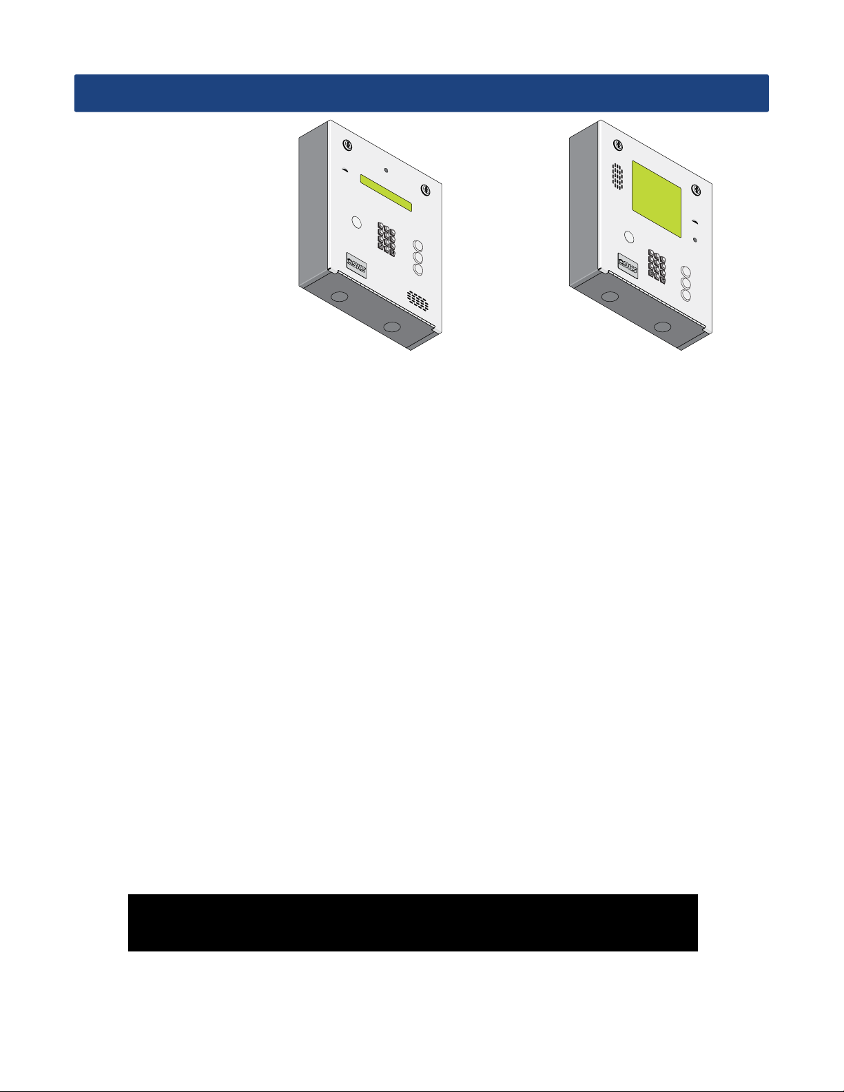
SPECIFICATIONS
1
2
3
4
5
6
7
8
9
A
0
Z
C
ALL
1
2
3
4
5
6
7
8
A
9
0
Z
C
AL
L
Features
1835
1837
• Can provide service for up to 3000 residents.
• Can store up to 8000 card, transmitter or digital PIN codes.
• System can be connected via a Cellular connection using DKS Cellular Services; via the Internet using DKS Data over the
Internet Services for VoIP and/or programming; POTS (Plain Old Telephone Service) using DKS IM Server or your own
modem - Note: DKS does not guarantee modem connections via the PSTN (Public Switched telephone Network).
• ONE TOUCH CALLING provides the easiest to use system on the market.
• System keypad will emit DTMF tones after a call is answered allowing the system to be used with auto-attendants,
answering machines, etc.
• Directory codes can be set from 1 to 4 digits in length and can be randomly assigned.
• Transaction buffer stores the last 8000 events and has its own backup power source to retain memory during power
outages.
• View the LIVE transactions “real-time” on a PC.
• Control the phone entry system relays directly from a PC (Rev Y and higher boards only).
• 31-security levels total (security level 00 always denies entry, security level 01 always admits entry), with 29 programmable
security levels, each with four time zones allows you to control and restrict user access as needed.
• Programmable holiday schedule.
• Facility codes can be enabled or disabled. Store up to 10 different facility codes.
• True Anti-Pass Back feature.
• Up to 255 programmable area codes (Rev E and higher boards only) allow the system to be used in areas requiring
10 and 11-digit dialing.
• Three internal relays allow the system to control a main entry point plus two additional entry points.
• System can be expanded to control up to 48 entry points in addition to the main entry point. Expansion boards are
required (one for each additional entry point) and are not included with the system. Expansion boards also provide output
for door ajar and forced entry alarms.
• Optional elevator control board(s) can control up to four elevators with each elevator serving up to 64 floors.
• System will interface with selected models of DKS DoorKing vehicular gate operators to provide gate operator information
and data (requires a Tracker Expansion board for each gate operator that is to send data to the system).
Included with the system is an extra random keyed cabinet lock. If desired, for added security against
unauthorized entry into the system, the standard lock may be replaced with the random lock.
Note: DoorKing cannot replace this specific lock or keys if lost.
DoorKing, Inc. reserves the right to make changes in the products described in this manual without notice and without obligation of DoorKing, Inc. to notify any persons
of any such revisions or changes. Additionally, DoorKing, Inc. makes no representations or warranties with respect to this manual. This manual is copyrighted, all rights
reserved. No portion of this manual may be copied, reproduced, translated, or reduced to any electronic medium without prior written consent from DoorKing, Inc.
4
1835-067-A-9-18

TABLE OF CONTENTS
Quick Quide Terminal Descriptions
Overview for System Keypad Programming
Important Notices FCC - United States, DOC - Canada Glossary
General Information Installation Guidelines and Safety Information
SECTION 1 - INSTALLATION
1.1 General Installation
1.2 Remove Components from Enclosure
1.3 Enclosure Dimensions
1.4 Install Enclosure
1.5 Memory Chip Replacement
1.6 Postal Lock Installation
1.7 UL 294 Compliant Tamper Switch
1.8 OPTIONAL Internal Card Reader Installation
1.9 OPTIONAL Camera Kit Installation
1.10 OPTIONAL Heater Installation
SECTION 2 - WIRING
2.1 Wiring Guidelines
2.1.1 Power
2.1.2 Wire Runs
2.1.3 Grounding
2.1.4 Surge Suppression
2.1.5 Expansion Boards and Elevator Control
2.1.6 Ferrite Filter
2.2 Terminal Descriptions
2.3 Telephone Entry System Wiring
2.3.1 ALL telephone Entry Systems - No Tracker Expansion Boards
2.3.2 Hardwired Tracker Expansion Boards
2.3.3 Tracker Expansion Boards using Wireless Communication
2.4 PC (DATA) and VOICE (PHONE) Connection Options
2.4.1 DoorKing Cellular Network Connection - Voice/Data Transfer
2.4.2a DoorKing VoIP/RS-232 Control Box - Voice/Data Transfer
2.4.2b DoorKing VoIP Internet Connection - Voice/Data Transfer
2.4.2c Third Party VoIP Internet Connection - Voice/Data Transfer
2.4.2d DoorKing TCP/IP Converter Mounting Position
2.4.3a DoorKing IM Server Modem Connection - Voice/Data Transfer
2.4.3b Dial-Up Phone Modem Connection - Voice/Data Transfer
2.5 Direct Connection to PC Options - Data Transfer ONLY
2.5.1 RS-232 Direct Connection - Data Transfer ONLY
2.5.2 RS-422/USB Direct Connection to PC - Data Transfer ONLY
2.5.3 TCP/IP Converter Direct Connection to PC - Data Transfer ONLY
SECTION 3 - PROGRAMMING
3.1 General Programming Information
3.1.1 Programming from a PC
3.1.2 Programming from the Telephone Entry System Keypad
3.1.3 System Memory Chip Identification
3.2 Setup Telephone Entry System for PC Programming
3.2.1 Master Code
3.2.2 Number of Area Codes Allowed
3.2.3 Call-Up Operation when Interfacing with DoorKing 1816 or 1820 Systems
3.2.4 Resident Elevator Button Relay Time
3.2.5 “Tone Open” Sound ON or OFF
3.2.6 RS-232 Speed Setting
3.2.7 Switch Input Feature
3.2.8 Elevator Control Feature
Software.
3.2.9 Single or Multiple Systems
System Keypad
3.2.10 DKS Data over IP Phone Number or System ID Number
3.2.11 Re-Program Memory Size, with/without Cards and Anti-Pass Back
3.2.12 LIVE Transaction Viewing from a PC - ON or OFF
Overview for System Keypad Programming
3.3 General Programming using the System Keypad
3.3.1 Relay Strike Time
3.3.2 Talk Time
3.3.3 Tone Open Numbers
3.3.4 Switch Input Relay(s) Activation
3.3.5 Touch-Tone / Rotary-Dial
3.3.6 Rotary-Dial 9 Relay(s) Activation
3.4 Programming Letters, Numbers and Messages
3.4.1 Programming Letters, Numbers from Keypad
3.4.2 Programming the User Message - 1835 System ONLY
3.4.3 Programming the Instruction Message - 1835 System ONLY
3.4.4 Programming the User Message - 1837 System ONLY
3.4.5 Programming the Instruction Message - 1837 System ONLY
Programming ONLY
NOT programmable from
when NOT using a PC
System Keypad Programming
Quick Guide - 1
Quick Guide - 2
3
4
5
5
6
7
8-9
10
11
12
13
13
14
15
15
15
15
16
16
16
16
17
18
18
19
20
21
21
22
22
22
23
23
23
24
24
24
24
25
25
25
25
26
26
26
27
27
27
27
28
28
28
28
29
29
30
31
32
32
32
33
33
34
34
35
35
36
37
38
39
1835-067-A-9-18
Table of Contents continued on next page
1

TABLE OF CONTENTS
3.5 Programming Phone Numbers and Names
3.5.1 Programming the Directory Code Length
3.5.2 Programming Directory Codes with 7-Digit Phone Number - NO Area Code
3.5.3 Programming Area Codes
3.5.4 Programming Directory Codes with Phone Numbers that use Area Codes
3.5.5 Programming Names
3.5.6 Deleting Individual Phone Numbers
3.5.7 Delete Names
3.5.8 Delete Area Codes
3.5.9 Delete phone Numbers
3.5.10 PBX Line Access Code Programming
3.5.11 Touch-Tone Dial Pause
3.6 Programming Device Codes
3.6.1 Programming Five-Digit Device Codes
3.6.2 Deleting Device Codes
3.6.3 Enabling Facility Codes
3.6.4 Programming Facility Codes
3.7 Programming Four-Digit Entry Codes
3.7.1 Programming Four-Digit Entry Codes
3.7.2 Delete Entry Codes
3.7.3 Entry Code Ranges
3.8 Anti-Pass Back
System Keypad Programming when NOT using a PC
3.8.1 Programming the Anti-Pass Back Mode
3.8.2 Re-Sync All Devices
3.8.3 Re-Sync Individual Devices
3.8.4 Reset Facility Counter
SECTION 4 - ADJUSTMENTS
4.1 Speaker Volume, Microphone and Feedback
4.2 LCD Display Contrast
4.3 Back-Lite Cutoff
4.4 Master Code Switch
4.5 Ring Pin Jumper
4.6 Relay 2 Jumper
4.7 Auto - 1816 Interface Jumper
4.8 HF - HS Jumper
SECTION 5 - SYSTEM OPERATING INSTRUCTIONS
5.1 Guest Instructions
5.2 Resident Instructions
5.2.1 Responding to a Guest Call
5.2.2 Using an Entry Code
5.3 System Administrator
5.3.1 Connecting to the Telephone Entry System from a Remote Location
5.3.2 Expansion Board Override HOLD OPEN Command
5.3.3 Relay Check
5.3.4 Time and Date Check
5.4 Miscellaneous Operating Instructions
5.4.1 Talk Time
5.4.2 Telephone Line Sharing
5.4.3 Connection to a PBX System
5.4.4 Areas with 10-Digit Dialing
5.4.5 Control Relays Directly from PC
SECTION 6 - MAINTENANCE
6.1 Troubleshooting
6.1.1 RS-232 Test
6.1.2 Wiegand Test
6.1.3 Elevator Control Board(s) Hardware Test
6.1.4 Elevator Board / Floor Hardware Test
6.1.5 Automatic Hang-up Options
6.1.6 Modem Output Level Adjustment
6.1.7 Display
Testing
6.1.8 Test Connection to
DKS Data
6.1.9 Turn DKS Data over IP ON or OFF
over IP
DKS Data over IP Phone Number or System ID Number
DKS Data over IP
6.2 Accessories
Wiring Schematics 1835 and 1837
SECTION 7 - LOG TABLES
7.1 Programming Information Tables
7.1.1 10 Area Codes
7.1.2 255 Area Codes
7.2 Resident Information
RESIDENT INSTRUCTION SHEET
40
41
41
42
42
42
43
43
44
44
44
44
45
45
45
45
45
46
46
46
46
47
47
47
47
47
48
49
49
49
49
50
50
50
50
51
51
52
52
52
53
53
53
53
53
54
54
54
54
54
54
55
55-56
57
57
57
58
58
58
59
59
59
60
61-62
63
63
63
64-65
66
67
2
1835-067-A-9-18

Important Notices
FCC – United States
This equipment has been tested and found to comply with the limits for a class A digital device, pursuant to Part 15 of the FCC Rules and
Regulations. These limits are designed to provide reasonable protection against harmful interference when the equipment is operated in a
commercial environment. This equipment generates, uses, and can radiate radio frequency energy and, if not installed and used in accordance
with the instruction manual, may cause harmful interference to radio communications. Operation of this equipment in a residential area is
likely to cause harmful interference in which case the user will be required to correct the interference at his own expense.
FCC Registration Number: DUF6VT-12874-OT-T
DOC - Canada
The Canadian Department of Communications label identifies certified equipment. This certification means that the equipment meets certain
telecommunications network protective, operational, and safety requirements. The Department does not guarantee the equipment will operate
to the users satisfaction.
Before installing this equipment, users should ensure that it is permissible to be connected to the facilities of the local telecommunications
company. The equipment must also be installed using an acceptable means of connection. The customer should be aware that compliance
with the above conditions may not prevent degradation of service in some situations.
Repairs to certified equipment should be made by an authorized Canadian maintenance facility designated by the supplier. Any repairs or
alterations made by the user to this equipment, or equipment malfunctions, may give the telecommunications company cause to request the
user to disconnect the equipment.
Users should ensure, for their own protection, that the electrical ground connections of the power utility, telephone lines, and internal metallic
water pipe system, if present, are connected together. This precaution may be particularly important in rural areas.
CAUTION: Users should not attempt to make such connections themselves, but should contact the appropriate electric inspection authority, or
electrician, as appropriate.
DOC Registration Number: 1736 4507 A
Notice:
The Load Number (LN) assigned to each terminal device denotes the percentage of the total load to be connected to a telephone loop which is
used by the device, to prevent overloading. The termination on a loop may consist of any combination of devices subject only to the requirement that the sum of the load numbers of all the devices does not exceed 100.
Notice:
DoorKing does not provide a power transformer on units sold outside of the United States. Use only transformers that are listed by a
recognized testing laboratory to power the telephone entry system. An Inherently Protected Transformer must be used to power this device.
1835 system require a 16.5-volt, 20 VA transformer. The model 1837 requires a 16.5-volt, 40 VA transformer.
Listing:
This product has been tested to and found to be in compliance with the UL 294 Safety Standard by Intertek Testing Services NA Inc. (a
Nationally Recognized Testing Laboratory) and is ETL listed.
UL 294 Performance Levels
Destructive Attack: Level I (Level II with Optional Hood Installed)
Line Security: Level I
Endurance: Level IV
Standby Power: Level I
Glossary
ACCESS CONTROL SYSTEM: A collection of means, measures and specific practices that when combined, form or compose a systematic
approach, which enables an authority to control access to areas and resources in a given physical facility. An access control system, within
the field of physical security, is generally seen as the second layer in the security of a physical structure.
ALARM: A condition indicating a state of alert or tamper detection.
ALARM SIGNAL: A transmission of an alarm condition or alarm report.
CONTROLLED AREA: A room, office, building, facility, premises, or grounds to which access is monitored, limited, or controlled.
EQUIPMENT: Any part of an electronic access control system, such as access control units, reader interface modules, access point actuators,
access point sensors, keypads, and the like.
PROTECTED AREA: A room, office, building, facility, premise or grounds to which access is monitored, and limited and/or controlled,
whereby the authorized person of the Access Control System may grant access to non-authorized persons.
RESTRICTED AREA: A room, office, building, facility, premise or grounds to which access is monitored, and limited and strictly controlled,
whereby only the administrator of the Access Control System shall issue credentials that will lead to access.
1835-067-A-9-18
3
General Information
• Prior to beginning the installation of the telephone entry system, we suggest that you become familiar with the instructions, illustrations, and wiring
guidelines in this manual. This will help insure that you installation is performed in an efficient and professional manner.
• The proper installation of the telephone entry panel is an extremely important and integral part of the overall access control system. Check all local
building ordinances and building codes prior to installing this system. Be sure your installation is in compliance with local codes.
• When used to control a door or pedestrian gate, try to locate the telephone entry system as near as possible to the entry point. The unit should be
mounted on a rigid wall to prevent excessive shock and vibration from closing doors or gates. Continuous vibration and shock from slamming doors
or spring-loaded pedestrian gates will damage the circuit board.
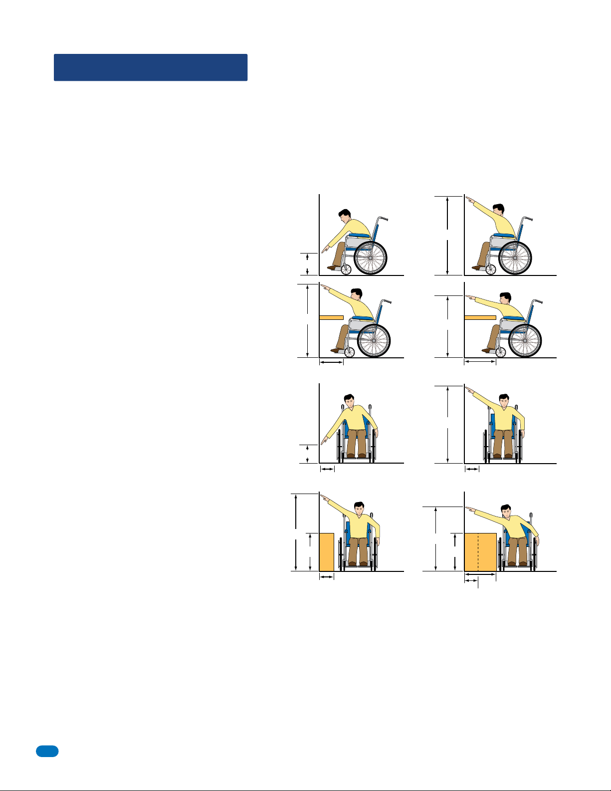
• ADA mounting requirements for door control (Ref: ICC/ANSI A117.1-2009). The requirements below apply ONLY when the telephone entry system is
being used to control entry through A PUBLIC DOOR ONLY. If this system is used to control entry through a vehicular gate or private entrance, the
dimensions noted below do not apply.
1. Unobstructed Forward Reach. Where a clear floor or
ground space allows only a forward approach to an object
and is unobstructed, mounting height shall be a minimum
of 15 inches (381 mm), and a maximum of
48 inches (1.22 m), above the floor or
ground to the operable controls.
2. OBSTRUCTED HIGH Forward Reach. If the high forward
reach is over an obstruction, reach and clearances shall
be as shown. NOTE: If the height of a control is 48"
maximum, then the length of the obstruction
must be 20" or less. If the height of a control
is 44" maximum, then the length of the
obstruction may be increased to 25" or less.
Under no circumstances should the unit be mounted directly to a moving door or gate.
Minimum
Height
Maximum
Height
15”
48”
Maximum
Maximum
Height
Height
48”
44”
48”
34”
25” or Less
Maximum Length of
10”
Clear Floor Space
Less than 24”
20” or Less
3. Unobstructed Side Reach. Where a clear floor or ground
space allows a parallel approach to an object and the side
reach is unobstructed, and the edge of the clear floor space
is 10 inches (255 mm) maximum from the object, mounting
height shall be a minimum of 15 inches (380 mm), and a
maximum of 48 inches (1.22 m), above the floor
or ground to the operable controls.
4. OBSTRUCTED HIGH Side Reach. If the side reach is over
an obstruction 10 inches or less, mounting height shall
be a maximum of 48 inches (1.21 m) above the floor or
ground to the operable controls. If the side reach
is over an obstruction greater than 10 inches,
but less than 24 inches, mounting height shall
be a maximum of 46 inches (1.17 m) above the
floor or ground to the operable controls.
• When used to control a vehicular gate with an automatic gate operator, the telephone entry system must be mounted a minimum of six (6) feet
away from the gate and gate operator, or in such a way that a person cannot operate the entry system and/or touch the gate or gate operator at
the same time.
• Be sure that the system is installed so that it is not directly in the traffic lane. Goose neck mounting post and kiosks work well for these type systems.
When planning where to locate the system, take into consideration traffic lane layouts, turn around lanes for rejected access, conduit runs, power
availability, etc.
• Environmental factors must also be taken into account. The units are designed for direct outdoor installations, however it is preferable to
protect them from direct exposure to driven rain or snow whenever possible.
• This telephone entry system contains a number of static sensitive components that can be damaged or destroyed by static discharges during
installation or use. Discharge any static prior to removing the circuit board from the lobby panel by touching a proper ground device.
• Instruct the end user to read and follow these instructions. Instruct the end user to never let children play with or operate any access control
device. This Owner’s Manual is the property of the end user and must be left with them when installation is complete.
Minimum
Height
Maximum
Height
48”
15”
34”
Maximum Length of
10”
Clear Floor Space
10” or Less
Maximum
Maximum
Height
Height
46”
Greater than 10”
4
1835-067-A-9-18

SECTION 1 - INSTALLATION
Destructive Attack: Level I (Level II with optional hood installed)
Line Security: Level I
Endurance: Level IV
Standby Power: Level I
Prior to installing the telephone entry system, we suggest that you become familiar with the instructions, illustrations, and wiring guidelines in
this manual. This will help insure that you installation is performed in an efficient and professional manner.
Order your telephone line to be installed at least two weeks prior to the planned telephone entry system installation date. This will assure
that a phone line is available when the unit is installed. The telephone company will require the following information from you:
Type: Touch Tone, Loop Start
Ringer Equivalence: 0.0 A
Jack Type: RJ11C
FCC Registration (US): DUF6VT-12874-OT-T
DOC (Canada): 1736 4528 A
Electrical Listing: Complies with UL 294 - ETL Listed
Caller ID: You may want to order caller ID blocking from the telephone company for the entry system phone line. Without caller ID blocking,
residents with the proper phone equipment WILL BE ABLE to identify the telephone number that the telephone entry system is installed on.
This may or MAY NOT be desirable.
Call Waiting: Residents may order call waiting from their local telephone company AFTER the system has been installed. They can avoid
missing calls coming from the telephone entry system while they are using their phone (No busy signal).
1.1 General Installation
There are different ways to mount the 1835/1837 (On a wall, in a wall, attached to a architectural style post, kiosk, etc). They need a telephone
line, power and communication wires run to them in conduit or inside a architectural style post. Feed all of the wires through the back or
bottom of the entry system using the existing knock-outs provided in the enclosures. DO NOT make any new holes in the enclosure to feed
wires through. Keep ALL the entry system’s wires away from any existing high voltage power wires a minimum of 6” to help prevent any noise
and hum pickup in the system’s phone line. The system MUST also be properly grounded to function correctly.
A
Z
3
2
L
L
A
6
1
C
5
9
4
8
7
0
A
Z
3
2
L
L
6
1
CA
5
9
4
8
7
A
Z
3
2
L
L
A
6
1
C
5
9
4
8
7
0
0
A
Z
3
2
L
L
A
6
1
C
5
9
4
8
7
0
DoorKing Self-Standing
On an Outside Wall
In a Lighted Kiosk
(Optional Flush
Mount Kit Shown)
Lighted Kiosk,
(Optional Flush
Mount Kit Required)
On a Architectural
Style Post
(Optional Hood Shown)
On an Inside Wall
WARNING If this telephone entry system is used to control a vehicular gate with an automatic gate operator, the telephone entry system
must be mounted a minimum of six (6) feet away from the gate and gate operator, or in such a way that the user cannot come into
contact with the gate or gate operator when using this entry system.
The telephone entry system contains a number of static sensitive components that can be damaged or destroyed by static discharges during
installation. Discharge any static prior to removing the circuit board by touching a proper ground device. GREAT care must be taken after
removing the components from the enclosure to protect them throughout the installation. Carelessness on your part is NOT covered under
warranty.
Make sure ALL dirt, metal or wood debris is removed from inside the enclosure after mounting it. A through cleaning of the enclosure is
needed before re-installing the components back into the system and wiring it. Any debris left inside could damage the control board and
cause the telephone entry system to malfunction during operation.
Included with the system is an extra random keyed cabinet lock. If desired, for added security against unauthorized entry into the system,
the standard lock may be replaced with the random lock. Note: DoorKing cannot replace this specific lock or keys if lost.
1835-067-A-9-18
5

1.2 Remove Components from Enclosure
1. Disconnect the two ribbon cables from the circuit board.
2. Remove the two screws from the upper corners of the circuit board.
3. GENTLY remove the circuit board by pulling it out of the main terminal.
4. Remove the two screws from the main terminal and remove the
ground wire locknut.
5. Remove five (5) locknuts from the faceplate hinge.
6. Remove the faceplate, main terminal (still wired), ribbon cables and
the circuit board, store them in a Safe Place until they need to be
re-installed.
Discharge any static
BEFORE removing
the circuit board by
touching a proper
Main Terminal Screw
ground device.
Enclosure
Circuit Board Screw
DOORKING 1892-010
BA
CKLIT
CU
T
E
OFF
S
IN
GLE
LINE
D
IS
PLAY
8 LINE
DISPLAY
CONTRA
ST
PH
ON
E
C
GN
D
PSW
MI
C
C
O
M
SPK
R
IMD
5
V
D
C
I
MC
Ground
Wire
DOORK
1491
I
N
-
010
G
Main Termina
AZ
2
C
2
RY
1
C
1
N
C
1
N
O
BAT
6AC
1
6AC1
Display
Ribbon
Cable
Keypad Ribbon
Cable
l
Faceplate Hinge Locknuts
2
P
1
P
Faceplate
6
1835-067-A-9-18
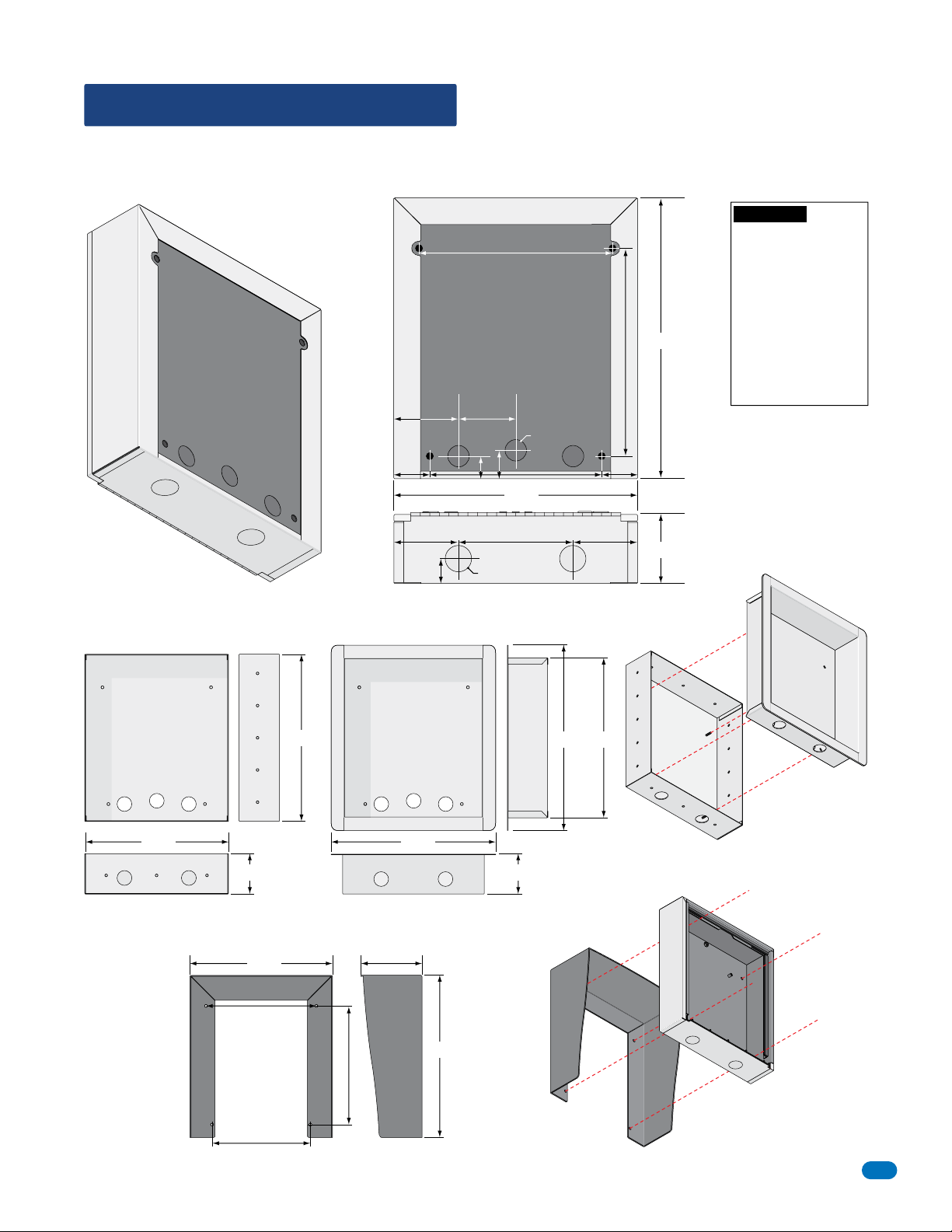
1.3 Enclosure Dimensions
Enclosure can be mounted directly to a wall, pilaster, post mounted using a OPTIONAL DoorKing architectural style mounting
post or recessed in a wall (OPTIONAL Flush Mount Kit). The OPTIONAL Hood can be mounted to enclosure if desired. Be sure
the unit is mounted securely and is not subject to vibration from closing doors or gates.
WARNING! If this entry
system is used to control
10.125”
Back View
3” 3”
1.125” Dia
1.5”
1.125”
1.25” 1.25”
9”
12.75”
Bottom View
6”3.5” 3.5”
1.5”
1.375” Dia
14.75”
10.875”
3.75”
a vehicular gate with an
automatic gate operator,
the entry system must be
mounted a minimum of
six (6) feet away from the
gate and gate operator, or
in such a way that a
person cannot operate the
entry system and touch
the gate or gate operator
at the same time.
OPTIONAL Flush Mount Kit (P/N 1814-200)
15.56”
13.61”
3.75” 3.76”
Trim RingRough-In Box
17.27” 13.08”
15.34”
OPTIONAL Hood (Stainless Steel P/N 1814-180, Black P/N 1814-185)
13.08”
10.125”
5.61”
Hood
14.88”
10.875”
Trim Ring
Rough-In
Box
Enclosure
1835-067-A-9-18
9”
7
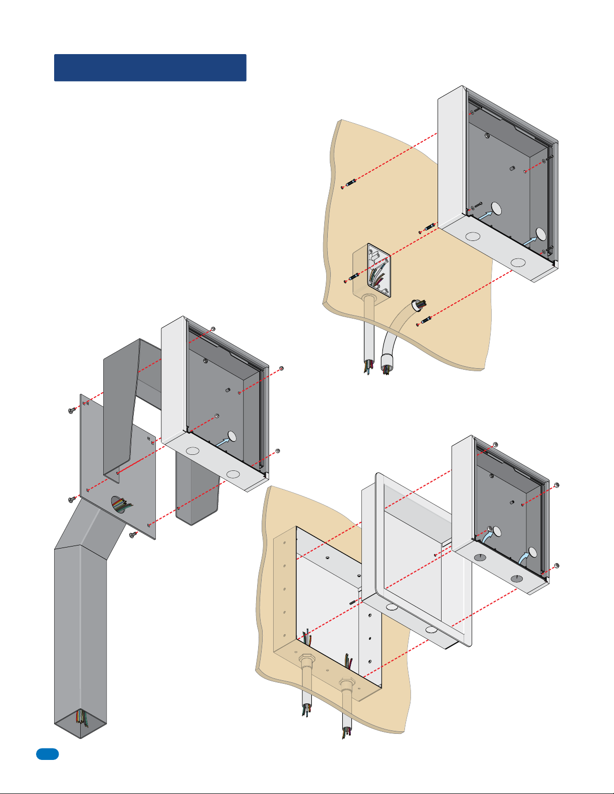
1.4 Install Enclosure
The illustrations below and next page show typical installations but specific
installations can vary from this. See previous page for dimensions.
1. Mount the enclosure using the mounting holes provided in the
corners (see next page for OPTIONAL flush mount kit OR hood
dimensions). Be sure that mounting screws (Not supplied) do not
protrude into the enclosure where they could cause a short on the
back of the circuit board. Make any necessary conduit connections
through the back or bottom of the enclosure using the existing
conduit knock-outs. DO NOT make any new conduit holes in the
enclosure.
2. Route all wiring through conduit or architectural post (not
supplied) into enclosure.
3. Clean out the enclosure. Make sure that all dirt, metal and/or
wood debris is removed.
4. Re-install components back into the enclosure (Reverse section
1.2 steps). Use the wiring schematics in the back of this manual to
help re-install the components if necessary. DO NOT apply any
power at this time.
Mount to a DKS
Architectural
Post
to junction box
Mounting Ho
OPTIONAL
Hood
E
nclosure
le
Knock-out
Examples of conduit runs that may be used, depending on how you choose to run
the wiring. Some installations will allow the conduit to be run outside the wall and
connect to the bottom of the enclosure but this is generally NOT recommended.
Wall
Use appropriate
hardware to secure
enclosure to the wall
(not supplied).
Conduit run
Mount
Conduit
sweep run
ON
a Surface
M
ou
nting Screw
Enc
Mounting
losure
Knock-ou
s
(Not supplied)
Hole
ts
Use hardware supplied with
architectural post to secure
enclosure to post.
Mount OPTIONAL
Hood
The hood (sold separately) fits
between the enclosure and the
surface it’s being mounted on if
desired.
Note: The hood CANNOT be
used with the flush mount kit.
Run all wires
inside post.
Mount
(OPTIONAL Flush Mount Kit Required).
IN
a Surface
Wall
Mounting Screws
(Not supplied
)
Rough-In
B
ox
Locknut
Enclosure
Knock-outs
T
rim
Ring
Mount OPTIONAL
Flush Mount Kit
Mount the rough-in box in the wall and trim
ring will fit inside of rough-in box.
Note: The hood CANNOT be used with the
flush mount kit.
8
Continued on next page.
1835-067-A-9-18
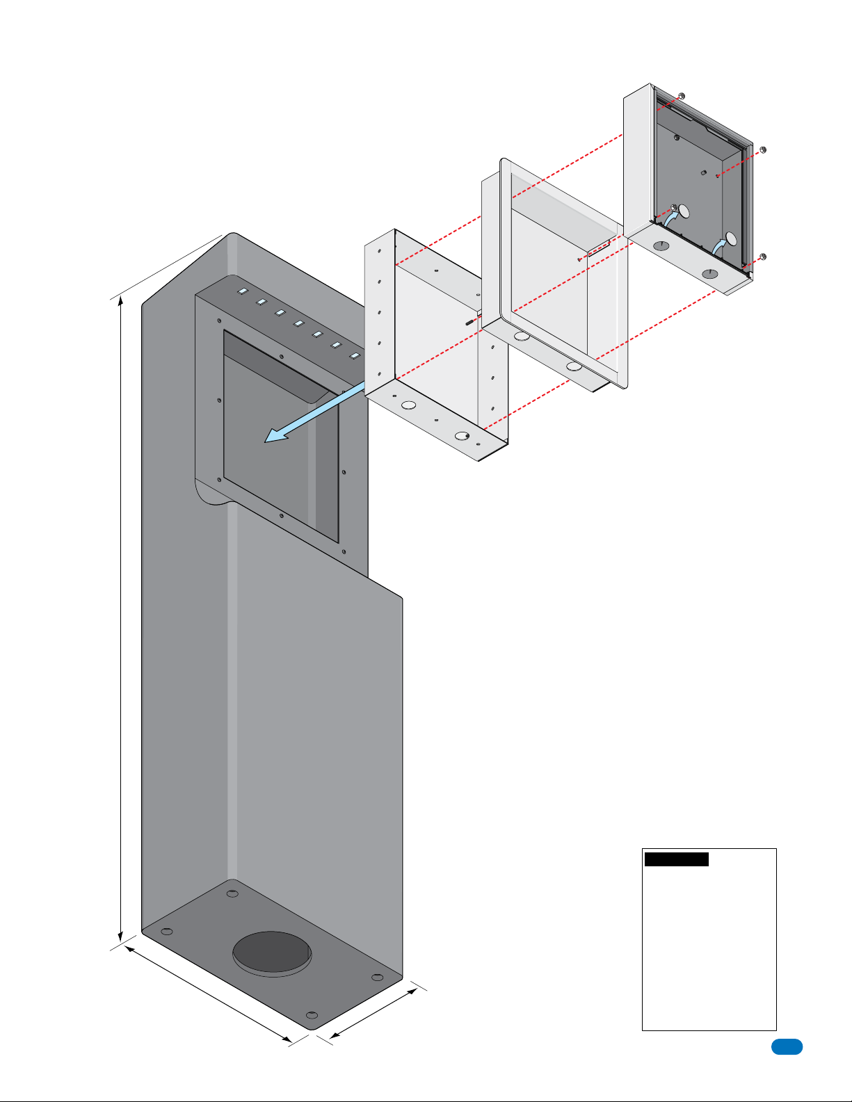
Mount OPTIONAL DKS Self-Standing Lighted Kiosk
The flush mount kit (Sold separately) is installed into the self-standing
kiosk (P/N 1200-???) to secure entry system in place.
Secure the rough-in box in the kiosk. Run all necessary wires to rough-in
box. Slide the trim ring into the rough-in box. Slide the enclosure in the
trim ring and secure them all together with hardware included in the kit.
Trim
Ring
Rough-In
Box
Locknut
Enclosure
Kno
ck-o
u
t
s
60”
18.5”
10”
WARNING! If this entry
system is used to control
a vehicular gate with an
automatic gate operator, the
entry system must be
mounted a minimum of six
(6) feet away from the gate
and gate operator, or in
such a way that a person
cannot operate the entry
system and touch the gate
or gate operator at the same
time.
1835-067-A-9-18
9
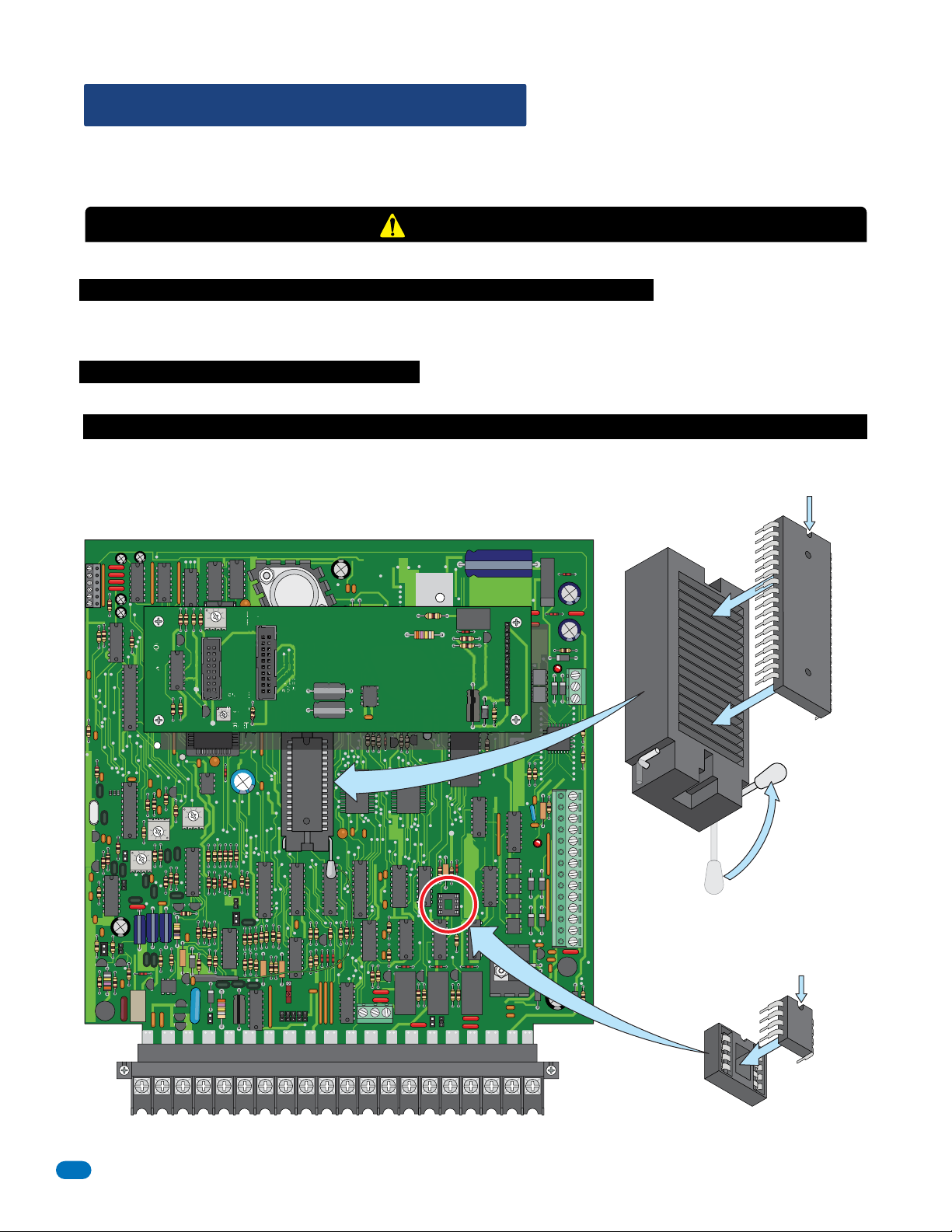
1.5 Memory Chip Replacement
The 1830 entry system is shipped with the memory chip already installed in the unit. However, if you need to
replace the memory chip in the NEW 1830 entry system or replace the memory chips in an OLDER 1830, follow the instructions
below. See 3.1.3 Memory Chip Identification for info about the memory chips in older 1830 entry systems.
CAUTION
Power MUST be OFF to the Circuit Board!!
DO NOT install the memory chip(s) with power to the telephone entry system turned ON. Attempting to install the memory
chip(s) with power on will irrevocably damage the chip(s). The memory chip(s) are static sensitive components. Discharge any
static electricity from your hands by touching a proper ground device before touching the control board. Handle the memory
chip(s) with care, the pins bend easily.
DO NOT install the memory chip(s) UPSIDE DOWN. this will cause permanent damage to the chip(s). Be sure that the
memory chip is seated correctly in the socket.
Discharge any static electricity from your hands by touching a proper ground device before installing chip(s)!
Dimple MUST be at
the top of the chip!
1830 Series Circuit Board Memory Chip(s) Location
RS 232
FEED
BACK
321
DOORKING 1892-010
MIC
VOL
321
321
SPK
VOL
321
CONTRAST
TONE ON
TONE OFF
RING
BACKLITE
CUTOFF
SINGLE
LINE
DISPLAY
8 LINE
DISPLAY
ON
MASTER
CODE
OFF
KEYPAD
Memory
ELEVATOR
1
2
3
Release
Locked
12345 67891011121314
NO
NO
NC C
NC
Dimple MUST be at
the top of the chip!
APB
Memor
y
16AC16ACBAT1NO1NC1C2RY2CAZIMC5VDCIMDSPKRCOMMICPSWCGNDPHONE
Note: NO APB chip
installed on NEW
1830 board, ONLY on
Press Fit
Be Careful!
older 1830 boards.
10
1835-067-A-9-18
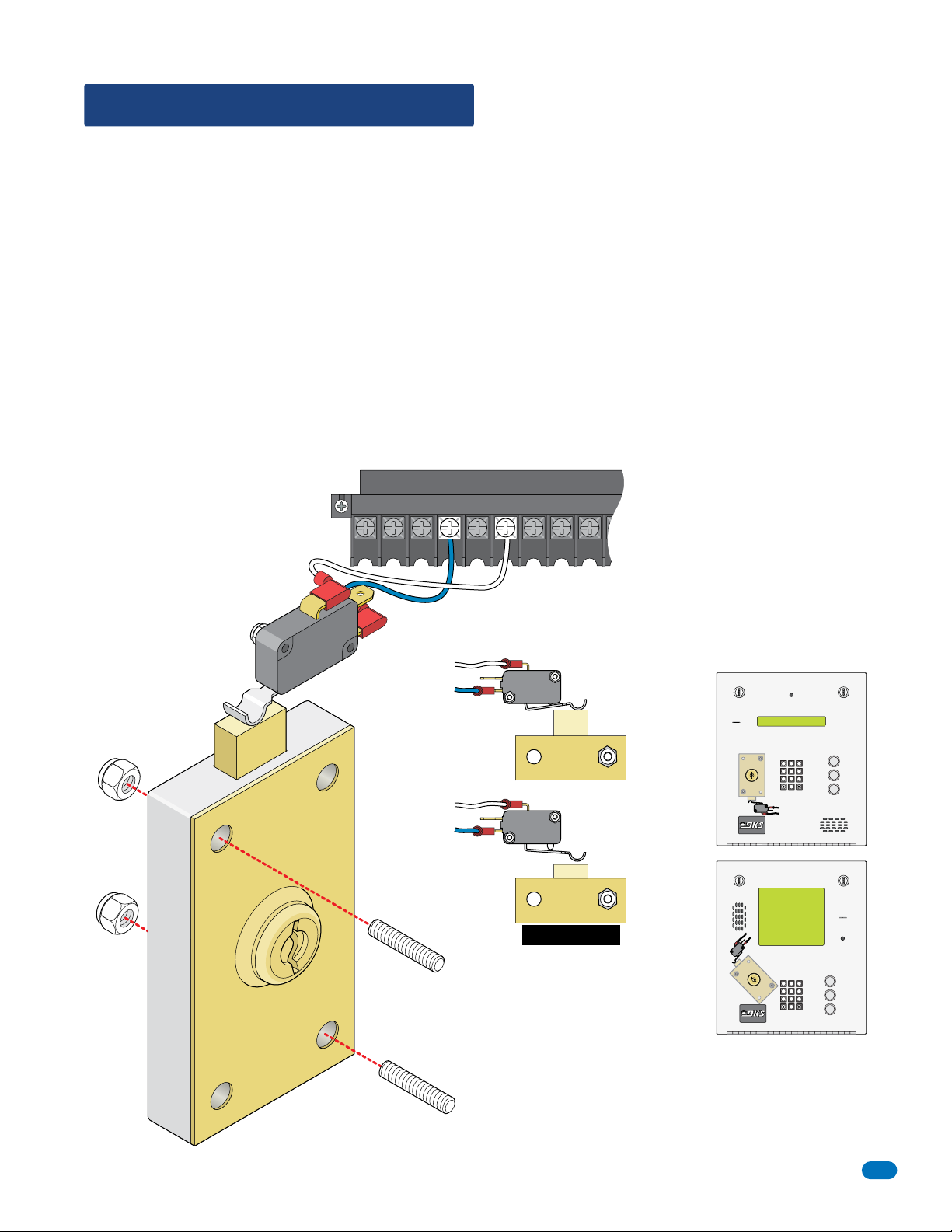
1.6 Postal Lock Installation
At some locations, such as gated communities, it will be necessary to provide access to the mail carrier so that they can
deliver the mail. Mail carrier access will be provided by the installation of an Arrow Postal Lock. This is the same lock that the
Post Office uses for gang mailboxes. These locks are not available to the public. The installer or the building owner/manager
will have to call the Post Office and arrange for the installation of this lock into the telephone entry system. All DoorKing
commercial telephone entry systems are designed to accept installation of the postal lock.
Prior to installation of the postal lock, be sure power to the telephone entry system is turned OFF.
1. Remove the hole plug on the faceplate of the telephone entry system.
2. Cut the wire tie wrapped around the switch ONLY when installing postal lock.
3. Remove the two hex nuts from the postal lock-mounting studs. Mount postal lock on the studs and secure with the hex nuts.
When the lock is installed, the pawl of the lock, in the extended position is depressing the switch. When the mail carrier inserts
his key and turns the postal lock, the pawl is withdrawn into the lock and the switch will activate the relay for the programmed
strike time, that has been programmed for this feature.
Factory default settings for the Postal Lock Switch: After the key has been turned, Relay 1 will activate (section 3.3.4) for One
(1) second of strike time (section 3.3.1). The switch input feature (section 3.2.7) is factory set to “activate a relay” and not “dial
a phone number”.
Main Terminal
IMC
5VDCIMDSPKRCOMMICPSWCGNDPHONE
Nylon Hex
Nuts
(Existing)
Pawl
White
Wire
m
Co
Blue
NC
Wire
Prewired
Postal Lock
Switch
Extended Pawl
Withdrawn Pawl
Existing postal
lock-mounting studs
located inside the faceplate
of the telephone entry system.
Com
NC
Com
NC
Relay Activates
1835
Lock
Position
1837
Lock
Position
Switch
Switch
1 2 3
4 5 6
7 8 9
1 2 3
4 5 6
7 8 9
A
Z
0
CALL
A
Z
0
CALL
1835-067-A-9-18
11
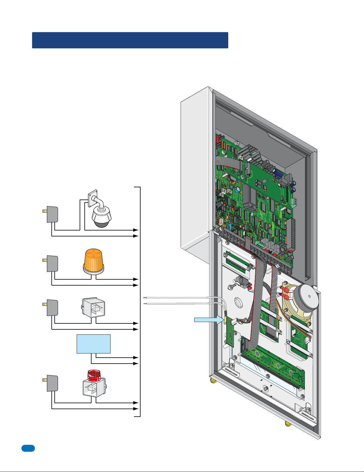
1.7 UL 294 Compliant Tamper Switch
The tamper switch needs to be connected to a security device or existing security system to comply with the UL 294 standard.
Connect the 2 white wires of the Normally Closed gravity activated dry contact tamper switch to whatever security setup you
desire. The gravity switch gets activated when the faceplate is opened. Repair and maintenance technicians may need to notify
the proper authorities BEFORE opening the entry system faceplate, depending on how your security of this system has been
setup.
Note: To comply with UL 294 Standard for Safety, the
tamper switch provided in this access control equipment
must be set to activate an alarm or alarm signal when
tripped. If the tamper switch is NOT connected to activate an
alarm or alarm signal, this will void UL 294 certification.
DOORKING 1892-010
BAC
KLI
CUTOFF
TE
SI
N
GL
E
LINE
DISPLAY
8 LINE
D
IS
C
P
ON
LA
TRAST
Possible Security Connections
Security
Camera
Separate
Camera
Power
Separate
Light
Power
Warning
Light
PHONE
CGND
PSW
Y
DOOR
149
K
IN
1-01
G
0
M
IC
CO
M
S
P
KR
IM
D
5
V
DC
I
M
C
Z
A
2
RY2C
1
C
1N
C
1N
O
BA
T
16AC
16
AC
White
Separate
Siren
Power
Siren
White
Tamper
Switch
Gravity Activated
Existing
(Dry Contact)
Building Alarm
System
Separate
Alarm
Power
12
Local
Alarm
System
P2
1
P
1835-067-A-9-18
1.8 OPTIONAL Internal Card Reader Installation
P2
14-Red
13-Black
#11 thru #14 will activate Relay 1
12-White
for its programmed strike time.
11-Green
10-Red
9-Black
#7 thru #10 will activate Relay 2
8-White
for its programmed strike time.
7-Green
12345 67891011121314
Install a OPTIONAL card reader as shown.
Red
Black
White
Green
Blue
Yellow
Not used
Log
o Plate
Support Bar
Internal Card Readers:
16AC16ACBAT1NO
DoorKing DK Prox - P/N 1815-302
HID Prox Point Plus - P/N 1815-380
ID-Teck RF Tiny - P/N 1815-215
Remove support bar from logo plate.
Card reader slides on existing stud
and is secured with support bar.
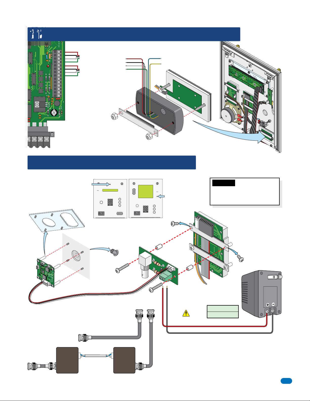
1.9 OPTIONAL Camera Kit Installation
Install a OPTIONAL camera kit as shown (P/N 1812-147).
1835 Camera Position
1837 Camera Position
A
Z
CALL
Discard
existing
screw.
Remove and discard plate
from camera.
1 2 3
4 5 6
7 8 9
A
Z
0
CALL
1 2 3
4 5 6
7 8 9
0
Faceplate
P
1
P2
Important: DO NOT power the
camera with the telephone entry
system’s 16.5 VAC 20 VA power
transformers.
Lighted Keypad
Remove
Plug from
Existing Studs
faceplate
Top
Camera
Inside
Faceplate
Mount camera on existing studs
on the inside of the faceplate after
removing plate from camera.
CCTV Circuit Board Connections
To Monitor, Video Recorder
To Monitor,
Video Recorder
VTT-2000
Video
Adapter
(At Monitor,
Video
Recorder)
RG-59U Coax (Not supplied)
500 ft. max.
UTP wire
1400 ft. max.
Mount CCTV circuit board on back
of lighted keypad as shown. Use
longer screws that comes with kit.
Plastic
Spacer
BNC
Connector
+
-
To B NC
VTT-2000
Video
Adapter
Connector
Red (+)
DoorKing offers video adapters (Not supplied) for up to 1400 ft
using unshielded twisted pair telephone wire. (P/N 1812-039)
(At 1830)
Plastic
Spacer
CCTV Circuit
Board
Power
Terminal
Black (-)
Polarity Matters!
Power Wire Run
16 AWG - 200 Ft
18 AWG - 100 Ft
Wire not supplied
Note: Transformer
Discard
existing
is for indoor use
screw.
and MUST be in a
protected enclosure
from weather when
using outdoors.
12 VDC
Output
1835-067-A-9-18
13
1.10 OPTIONAL Heater Installation
Install OPTIONAL heater as shown (P/N 2600-584). For cold weather climates where temperatures routinely drop below 40°F
(4°C). The thermostat will automatically control the temperature inside operator housing.
DOORKING 1892-010
BACKLI
CUT
TE
OFF
SI
N
G
LE
LINE
DISPLA
Y
8
LI
NE
D
I
SPLAY
C
ONTRAS
T
D
OOR
149
K
IN
1-
010
G
PHONE
CGND
PSW
M
IC
COM
P
KR
M
DS
5VDCI
I
M
C
Z
2
CA
RY
1N
C1C2
1N
O
B
A
T
1
6
AC
16A
C
Attach the thermostat on the bottom inside of the
cabinet as far from heater as possible. DO NOT
position the thermostat right next to the heater.
Built-in magnets will secure thermostat in place.
Thermostat will automatically turn heater on at
approximately 40°F (4°C) and off at 55°F (12°C).
12 VAC
40 VA
Output
Wire polarity
does not matter
HOT
Faceplate
Attach the heater in the center of
the faceplate. Built-in magnets
will secure heater in place.
The heater gets VERY HOT, DO NOT allow
existing components or wires to come in
contact with the metal heater housing.
14
P2
P1
Note: Transformer is for indoor use
and MUST be in a protected enclosure
from weather when using outdoors.
Up to 100 feet, use 18 AWG - 600 volt insulated wire.
Up to 200 feet, use 16 AWG - 600 volt insulated wire.
DO NOT run heater power wires over 200 feet or use
smaller wire than specified. Route wires to avoid
contact with the resistors on the telephone entry
system control board.
Important: DO NOT power the
heater with the telephone entry
system’s 16.5 VAC 20 VA power
transformers.
1835-067-A-9-18
SECTION 2 - WIRING
Prior to installing wiring to the telephone entry system, we suggest that you become familiar with the instructions, illustrations,
and wiring guidelines in this manual. This will help insure that you installation is performed in an efficient and professional
manner.
The wiring of the telephone entry panel is an extremely important and integral part of the overall access control system. Use
proper wire for the communication line, power wires, and be sure that the system is properly grounded. Check all local building
ordinances and building codes prior to installing this system. Be sure your installation is in compliance with local codes.
Telcom Access Standards. It is not permissible for customers to use the telcom network lead-in cable to provide the intercom
function between the gate and the house. New Zealand Customers: All door and gate entry systems wiring must comply with
PTC106: March 2008, Section 9.
WARNING If this telephone entry system is used to control a vehicular gate with an automatic gate operator, the telephone
entry system must be mounted a minimum of six (6) feet away from the gate and gate operator, or in such a way that the
user cannot come into contact with the gate or gate operator when using this entry system. If this unit has been installed
closer to the automated vehicular gate, do not proceed with any wiring until the unit has been moved and re-installed so
that it is in compliance with these instructions.
This telephone entry system contains a number of static sensitive components that can be damaged or destroyed by static
discharges during installation or use. Discharge any static prior to removing the circuit board from the enclosure by touching
a proper ground device.
2.1 Wiring Guidelines
2.1.1 Power
Use only the two (2) supplied transformers (or UL listed equivalent) to power the telephone entry and access control system
and any 26, 30 and 31 Bit wiegand input devices that use 16.5 VAC, 20 VA. DO NOT power any other devices (expansion
boards, electric strikes, magnetic locks etc.) from these power transformers.
Note: Transformers are not supplied on units sold outside the United States. An Inherently Protected Transformer must be used
to power this device. Use only transformers that are listed by a recognized testing laboratory to power the telephone entry
system.
Two 16.5 VAC, 20 VA for 1835.
One 16.5 VAC, 20 VA and
One 16.5 VAC, 40 VA for 1837.
Do Not Connect To A
Receptacle Controlled
By A Switch.
Up to 100 feet, use 18 AWG, 600 volt insulated wire.
Up to 200 feet, use 16 AWG, 600 volt insulated wire.
The importance of proper AWG power wiring cannot be over stressed!
Power wires are susceptible to noise and hum pickup; therefore
it is preferable that you keep power wire runs as short as possible.
Wire polarity does not matter
A
1 2 3
4 5 6
Z
7 8 9
0
CALL
“Optional” 12 volt .8 amp hour gel-cell batteries (DoorKing P/N 1801-008) can be installed to provide stand-by power in the
event of a power outage. Two batteries are required, one for the system power and one for the auxiliary terminal power.
2.1.2 Wire Runs
Be sure that you use proper wire that has an insulation
rated for an underground environment. All wires
should be placed in conduits. Proper pre-planning can
greatly ease the installation and wiring of this system.
Always check with the local building code to determine
the type of wire required in your municipality.
DO NOT run high voltage (115 V) power lines and low voltage/communication lines in the same conduit. These should be in
separate conduits at least six (6) inches apart. Be sure that all phone line wiring is twisted and completely isolated from ground.
Wiegand wire runs are 500-feet maximum. Use
6-conductor stranded wire with overall shield. 18, 20,
22 or 24 gauge is sufficient for these connections.
1835-067-A-9-18
Underground Cutaway
Low Voltage/
Communication
Wire Conduit
A
1 2 3
4 5 6
Z
7 8 9
0
CALL
Electrical field from high voltage wires.
6” minimum
500 ft Max
High Voltage
Power Wire
(115 V) Conduit
26, 30, 31-Bit
Wiegand Device
15

2.1.3 Grounding
Proper grounding of this system is a requirement. To be effective, ground connections should be made with a minimum 12
AWG, 600 volt insulated wire to a ground point within 10 feet of the telephone entry system. The ground point must be at an
electrical panel, a metallic cold water pipe that runs in the earth, or a stainless steel grounding rod driven at least ten (10) feet
into the soil. A architectural style mounting post anchored to concrete does NOT make a good ground.
Some Acceptable Ground Sources
IMPORTANT: Ground wire shown without
safety protection for clarity. Make sure
Electrical
Panel
Ground
Wire
ground wire is protected from being
touched or electrical shock could occur!
Ground
Wire
Ground to an existing electrical system.
Ground to a metallic cold water pipe.
Grounding rod 10 feet in soil.
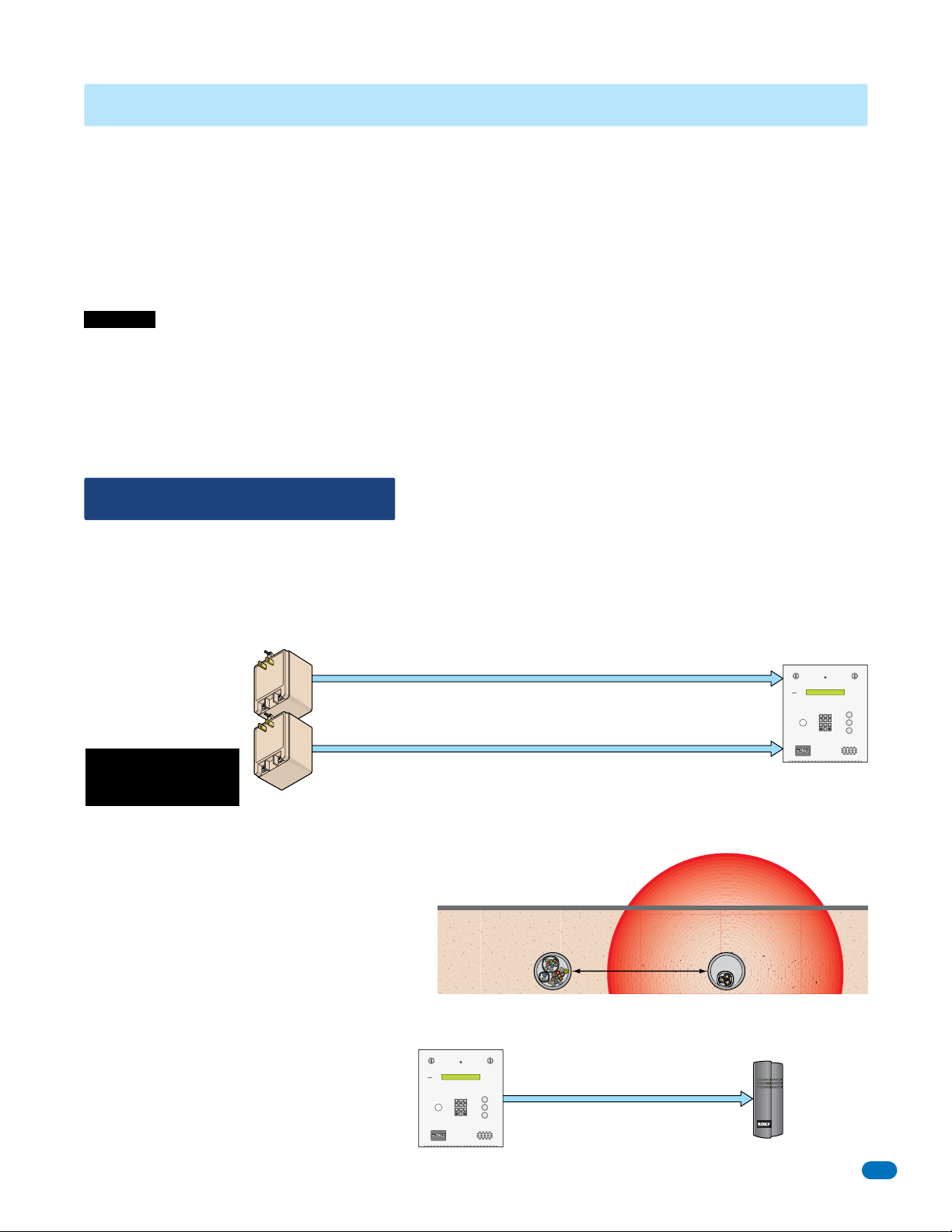
2.1.4 Surge Suppression
The use of surge suppressors can significantly reduce the chance of component failure because of static charges or surges.
DoorKing recommends Installing a Phone Line surge suppressor (DoorKing P/N 1877-010 or equivalent) and a Low Voltage
surge suppressor (DoorKing P/N 1878-010 or equivalent) to help protect the entry system from power surges.
Phone Line Surge Suppressor
A
1 2 3
4 5 6
Z
7 8 9
0
CALL
A
1 2 3
4 5 6
Z
7 8 9
0
CALL
Phone Company
Install on each
16.5 VAC Transformer
Phone line surge suppressor
1877-010
PHONE LINE
within 10 ft of entry system.
Surge suppressor within 3 ft of ground source.
Low Voltage Surge Suppressor
Low voltage surge suppressor
1878-010
POWER LINE
within 10 ft of entry system.
Surge suppressor within 3 ft of ground source.
2.1.5 Expansion Boards and Elevator Control
I
f Expansion Boards are being used with this system, refer to the Installation and Wiring manual that came with the Expansion
boards, for detailed information on wiring Expansion boards to the PC programmable telephone entry system.
If Elevator Control is used with this system, refer to the Elevator Control Installation and Wiring manual for detailed information
on wiring the elevator control boards to this system and to the elevator push button control panel.
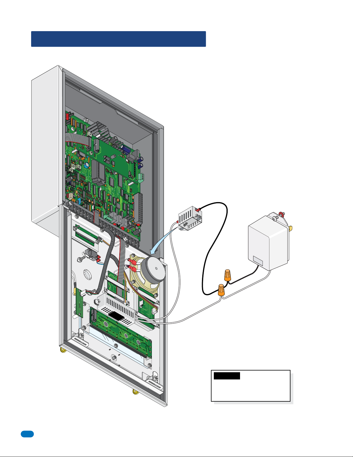
2.1.6 Ferrite Filter
The Telephone Entry System comes with two (2) Ferrite Filters. These will help
prevent noise and hum pickup in the phone lines. One is installed around the 16 VAC
power wires on the main terminal #19 and #20. The second is installed around all the
wires connected to the aux terminal.
Clip Release
C
Main Terminal
1N
2RY
2C
15
14
16
#1
6AC
1
6AC
1
T
BA
O
N
1
20
19
18
7
1
16
Power Wires
on all models
To install the ferrite filter, release the
clip on the side to open the filter,
place the wires in the circular core
and snap the filter closed.
14
13
12
11
10
9
8
7
6
5
4
Aux Terminal
3
2
1
Auxiliary Wires
Clip Release
#2
1835-067-A-9-18
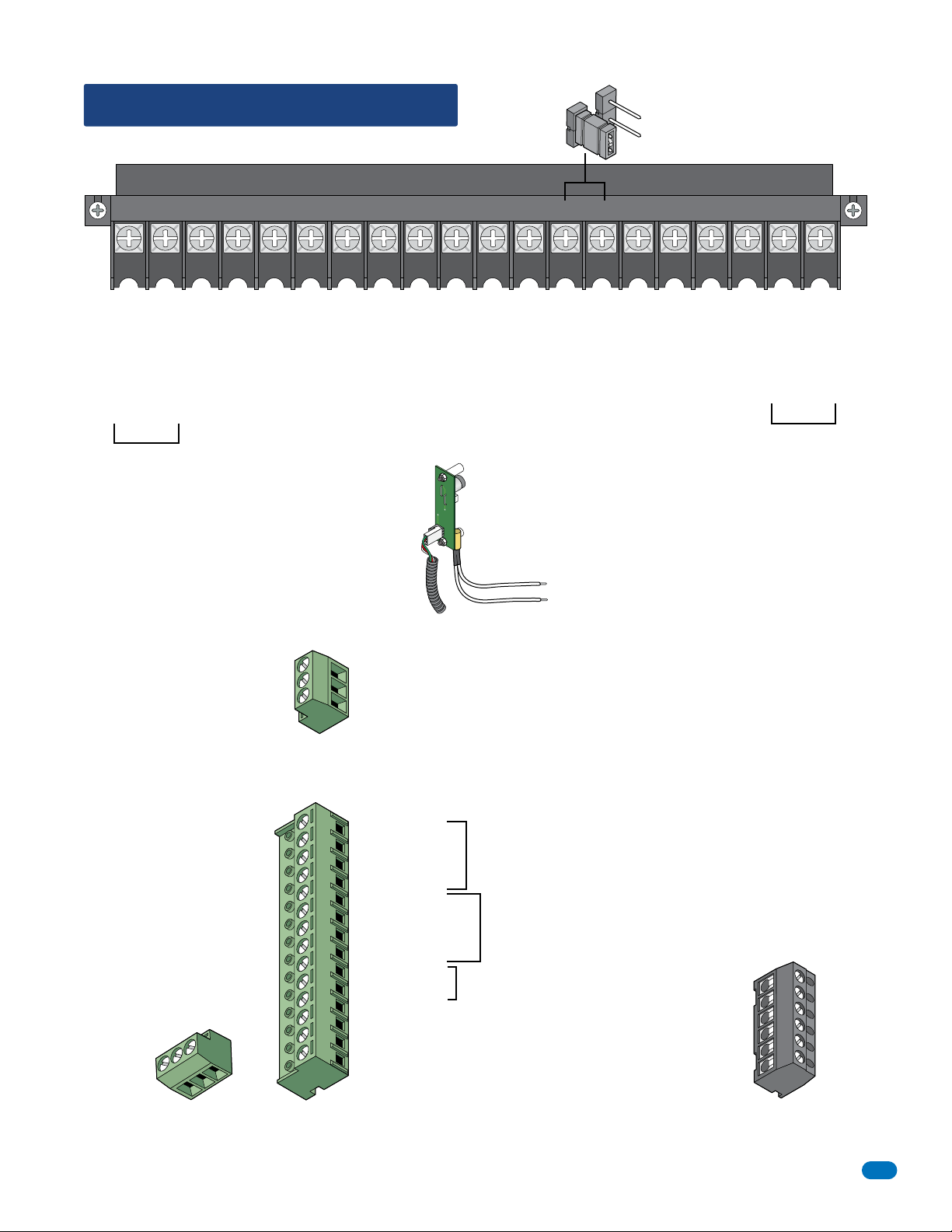
2.2 Terminal Descriptions
See section 4 on page 51 for the locations of the terminals on the circuit board.
Main Terminal
NO
Relay 2 Note: Normally Open and
NC
Normally Closed relay jumper is
used to set Relay 2 input on the
circuit board (See section 4.6).
PHONE
CGND
COMMICPSW
5VDCIMDSPKR
16AC16ACBAT1NO1NC1C2RY2CAZIMC
1234567891011121314151617181920
Phone Line Connection
Phone Line Connection
1600 ft. max. with 22 AWG wire.
(Wiring MUST be twisted and completely isolated from the ground)
Earth Ground Only (See Section 2.1.3).
800 ft. max. with 24 AWG wire.
Microphone Input.
Switch Input. A closure between terminals 4 and 6 will cause the designated relay(s) to activate for
the programmed strike time or dial a phone number – see 3.2.7. The Postal Switch is connected here.
Speaker Output.
Common for switch input #4, microphone,
speaker, AZ & CALL buttons and battery neg.
5 VDC Power for LED lighting.
(Not used).
“Z” Button Input.
(Not used).
16 VAC Input Power
16 VAC Input Power
Back-up Battery POSITIVE
100 ft. max. with 18 AWG wire.
200 ft. max. with 16 AWG wire.
20 VA min. for 1835, 40 VA min. for 1837.
For Phone System Only. (connect negative to terminal 6)
Relay 1 Normally Open – 30 Volt, 3 Amp max.
Relay 1 Normally Closed – 30 Volt, 3 Amp max.
Relay 1 Common – 30 Volt, 3 Amp max.
Relay 2 Contact – 30 Volt, 3 Amp max.
Relay 2 Common – 30 Volt, 3 Amp max.
“A” Button Input.
UL 294
Tamper
Switch
Note: Located under microphone
board (See Section 1.7).
Elevator Control
Terminal
Non-Removable
Note: Connect to the Elevator Control Board (2348-010).
See Elevator Control Board Manual 2348-065 for more info.
1
1 DATA 1 – Connect to terminal 20 of elevator control board.
2
2 DATA 0 – Connect to terminal 21 of elevator control board.
3
3 COMMON – Connect to terminal 22 of elevator control board.
1835-067-A-9-18
Normally Open – 30 Volt, 3 Amp max.
Normally Closed – 30 Volt, 3 Amp max.
Common – 30 Volt, 3 Amp max.
C
NC
NO
Relay 0 Terminal
Non-Removable
Aux Terminal
Removable
14
14 +12 VDC Power.
13
13 Common.
12
12 DATA 1.
11
11 DATA 0.
10
10 +12 VDC Power.
9
9 Common.
8
8 DATA 1.
7
7 DATA 0.
6
6 16 VAC Output.
5
5 16 VAC Output.
4
4 Back-up Battery NEGATIVE (For Wiegand Only).
3
3 Back-up Battery POSITIVE (For Wiegand Only).
2
2 16.5 VAC Input Power – 20 VA.
1
1 16.5 VAC Input Power – 20 VA.
(Powers RS-232, elevator control and Wiegand)
Note: The 14-pin aux terminal can be removed for easy
wiring. Expansion boards are connected here when used.
See Expansion
26, 30 and 31 Bit
Wiegand input (Card Reader)
activates Relay 1 for
programmed strike time
26, 30 and 31 Bit
Wiegand input (Card Reader)
activates Relay 2 for
programmed strike time
For card readers that have additional
lighting for outdoor use.
Tracker Board
Manual
2358-065 and
section 2.3.2,
2.3.3 for more
information.
Transmit Data 1
Receive Data 2
Request to Send 3
Clear to Send 4
Signal Ground - Shell 5
Not used 6
Note: Located in the upper left corner of circuit
board. The 6-pin terminal can be removed for
easy wiring. Connects a PC (See Section 2.5.1).
RS-232
Terminal
Removable
1
2
3
4
5
6
17
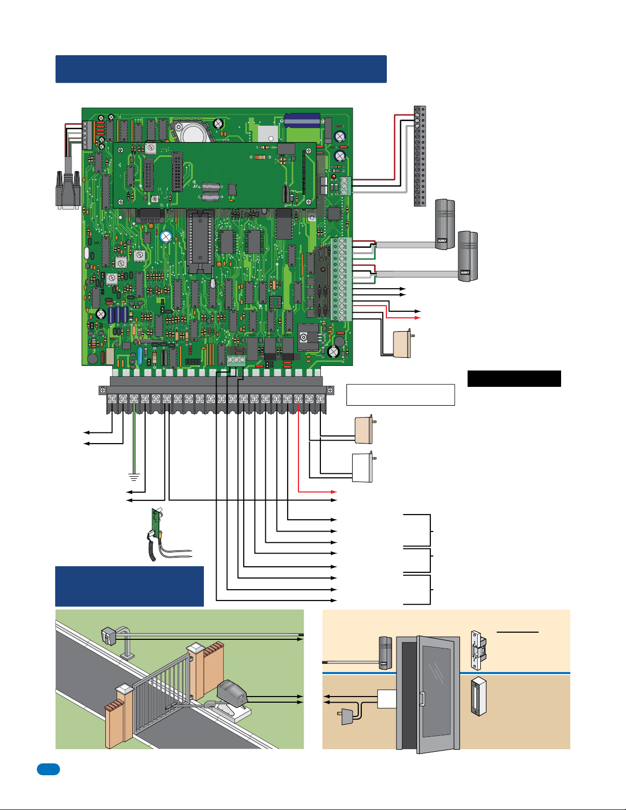
2.3 Telephone Entry System Wiring
2.3.1 ALL Telephone Entry Systems - NO Tracker Expansion Boards
RS 232
1
2
3
4
5
6
DOORKING 1892-010
RS-232
PC Connection See sections 2.4 and 2.5 for wiring RS-232.
321
SPK
VOL
FEED
BACK
321
1816
HF
HS
Central Office
Phone Line Input
touch tone, loop start
“PHONE”
“PHONE”
Wiring MUST be twisted and
completely isolated from ground.
See section 2.1.4.
“CGND” Ground
See section 2.1.3.
“PSW” & “COM”
Switch Input -
See section 1.6 for Postal lock
A switch closure across these
terminals activates Relay 1 for its
See section 3.2.7 Switch Input
Telephone Entry Systems:
Control up to 3 entry points with ONLY the system circuit board.
Note: Separate elevator control board required for elevator control.
Note: When more than 3 entry points are needed to be controlled,
expansion boards will be required to accomplish this, see next 2 pages.
connection.
programmed strike time.
Feature.
321
MIC
VOL
321
TONE OFF
RING
BACKLITE
CUTOFF
SINGLE
LINE
DISPLAY
CONTRAST
TONE ON
Main Terminal
UL 294
Tamper
Switch
(See Section 1.7).
8 LINE
DISPLAY
KEYPAD
Elevator
Control
ELEVATOR
Terminal
1
2
3
#11 thru #14
These terminals will activate
Relay 1 for its programmed
Red
strike time.
Black
White
#7 thru #10 These terminals will
Green
activate Relay 2 for its programmed
Red
strike time.
Black
White
Green
16.5 VAC
Auxiliary Terminal
16.5 VAC
12345 67891011121314
ON
MASTER
CODE
OFF
5VDCIMDSPKRCOMMICPSWCGNDPHONE
Relay 0
NO NC C
Relay 2 Jumper
NO
NC
16AC16ACBAT1NO1NC1C2RY2CAZIMC
Red (Pos)
Black (Neg)
Power Input transformer for the phone system AND
Power Input transformer for the Aux Terminal must
be connected for the system to operate.
20 VA
Power wire
polarity does
not matter.
40 VA
“BAT” & “COM” - 12 VDC Back-Up Battery Input (Phone System)
Back-up battery power for the phone system ONLY. A separate back-up battery is used for Wiegand devices
connected to the auxiliary terminal when back-up battery power is being used. See aux terminal #3 & #4.
Black (Neg)
Red (Pos)
20 VA
Power wire
polarity does
not matter.
Power Input for Phone System
20 VA power for the 1835 phone system ONLY.
DO NOT use a 40 VA transformer for the 1835.
Power Input for 1837 Phone System
40 VA power for the 1837 phone system ONLY.
DO NOT use a 20 VA transformer for the 1837.
“1NO” - Normally Open (NO)
“1NC” - Normally Closed (NC)
“1C” - Common (C)
“2RY” - Contact (NO or NC)
“2C” - Common (C)
NO - Normally Open
NC - Normally Closed
C - Common
19
20 - DATA - 1
21 - DATA - 0
22 - COMMON
23
24
“Optional” Elevator Control
25
26
Board Required for Elevator
27
28
Control
29
Power for relays on elevator control board is NOT provided
30
by the system. Use separate UL listed power supply.
31
See Elevator Control Board Manual 2348-065.
32
33
34
35
36
#5 & #6 - 16 VAC Output: Can be used to power lights on
card readers that have additional lighting for outdoor use.
#3 & #4 - 12 VDC Back-Up Battery Input (Aux Term)
Back-up battery power for Wiegand inputs ONLY.
A separate back-up battery is needed for the phone system.
Power Input for Aux Terminal
14-Pin aux terminal.
Powers RS-232, elevator control and Wiegand inputs.
Relay 1 Input
Relay 2 Input
“2RY” Contact is set NO or NC with Relay 2 Jumper on board.
See section 4.6
(Left terminal on elevator control board)
Wiegand Input (Relay 1)
26, 30 and 31-Bit Card Reader Input: Use 6 conductor,
stranded with overall shield. 18, 20, 22 or 24 gauge.
See section 2.1.2.
Wiegand Input (Relay 2)
26, 30 and 31-Bit Card Reader Input: Use 6 conductor,
stranded with overall shield. 18, 20, 22 or 24 gauge.
See section 2.1.2.
Do Not Connect Power To A
Receptacle Controlled By A Switch.
Power Transformers:
Use ONLY 16.5 VAC UL
Listed Transformer.
Run 18 AWG wire up to
100 Ft. Run 16 AWG wire
up to 200 Ft.
See section 2.1.1, 2.1.3
and 2.1.4 for further
information.
Relays activate a door lock
or a gate operator for their
programmed strike time at
a controlled access point.
Relay 0 Input
Basic Door Control ComponentsBasic Gate Control Components
500 ft max.
Card
Reader
To a Wiegand Input Aux. Terminal
To #5 & #6 aux. terminal
for additional lighting on
card reader.
Gate Operator
To a Relay Input
Gate Operator
is wired to
Normally Open
(NO) relay
input.
To a
Wiegand
Input Aux.
Terminal
500 ft max.
To a
Relay Input
Lock Power
UL listed
Card Reader
Door
Lock
Power for electric strike or magnetic
lock is NOT provided by the system.
Use separate UL listed power supply.
18
Door Locks
Electric strike is wired
to Normally Open (NO)
relay input.
Magnetic lock is wired to
the Normally Closed (NC)
relay input.
1835-067-A-9-18
 Loading...