

DoorKing 1833, 1836, 1837, 1838 Installation And Owner's Manual

HARDwired Installation/
Tracker Expansion Board
Tracker Expansion Board
Owner’s Manual
Tracker Expansion Board
Tracker Expansion Board
Wiegand Compatable
Use this manual for circuit board 2358-010 Revision B or higher.
For Models:
1833, 1835, 1837 and 1838 Multi-Door Access Controller
1
2
3
4
5
6
7
8
9
10
11
12
13
14
15
16
17
18
19
20
BOARD ADDRESS
ON
8
7
1
6
5
4
3
0
RF
SECURE
RF
DATA
STATUS
9
0
1
2
OUTPUT
ALARM
RF
CODE
CODE
CODE
RELAY
SENT
GOOD
BAD
NC
NO
RESET
ENT
RELAY
AUX
RELAY
NC
NO
2358-010
NC
NO
2358-065-L-7-16
Provides Access Control System expansion to
manage Up to 24 additional Access Points.
Quad Board
21
22
23
24
25
26
27
28
29
30
31
32
33
34
Enclosure
(Not Included)
Single Board
Enclosure
with Built-In
Card Reader
(Not Included)
Single Board
Enclosure
(Not Included)
Date Installed:
Installer/Company Name:
Phone Number:
Leave Manual with Owner
UL 325 Compliant
Circuit Board
Serial Number(s)
and Revision Letter:
Copyright 2016 DoorKing, Inc. All rights reserved.


TABLE OF CONTENTS
SECTION 1 - TRACKER EXPANSION BOARD INTRODUCTION 2
1.1 General Information
1.2 General System Layout
1.3 Tracker Expansion Boards Layout Options
1.4 Tracker Expansion Board Overview
1.5 Board Input Descriptions
1.6 Setting Board Address (Software - System Relay)
1.7 Relay Identification (Software - System Relay)
SECTION 2 - INSTALLATION 8-9
2.1 Single Board Enclosure
2.2 Quad Board Enclosure
2.3 Single Board Enclosure with Card Reader
10
10
11
SECTION 3 - HARDWIRING 11
3.1 General HARDwiring Information
3.2 Board Addresses 3-10 Communication Line HARDwiring
3.3 Board Addresses 11-18 Communication Line HARDwiring
3.4 MAX Boards Communication Line HARDwiring
3.5 Basic Board Wiring Options at Access Point
3.6 Alarm Wiring Options at Access Point
3.7 All Available Devices at Access Point
3.8 Typical Dual Mode Wiring at 2 Access Points
3.9 Quad Box Wiring
3.10 Gate Operator Data Wiring - Optional Control Wiring
11
12
13
14
15
16
17
18
19
20-22
2
3
3
4
5
6
7
SECTION 4 - PROGRAMMING 23
4.1 LED and Button Descriptions
4.2 Programming
4.3 Programming Step Descriptions
SECTION 5 - TROUBLESHOOTING 29
5.1 Wiegand Device Data
5.2 Gate Operator Data
5.3 Gate Operator Event (transaction) Reports
5.4 Complete System Information
DoorKing, Inc. reserves the right to make changes in the products described in this manual without notice and without obligation of DoorKing, Inc. to notify any persons
of any such revisions or changes. Additionally, DoorKing, Inc. makes no representations or warranties with respect to this manual. This manual is copyrighted, all rights
reserved. No portion of this manual may be copied, reproduced, translated, or reduced to any electronic medium without prior written consent from DoorKing, Inc.
2358-065-L-7-16
23
23-25
26-28
29
30
31
32
1
SECTION 1 - TRACKER EXPANSION BOARD INTRODUCTION
Use this manual for Tracker Expansion Board 2358-010 Rev B or higher.
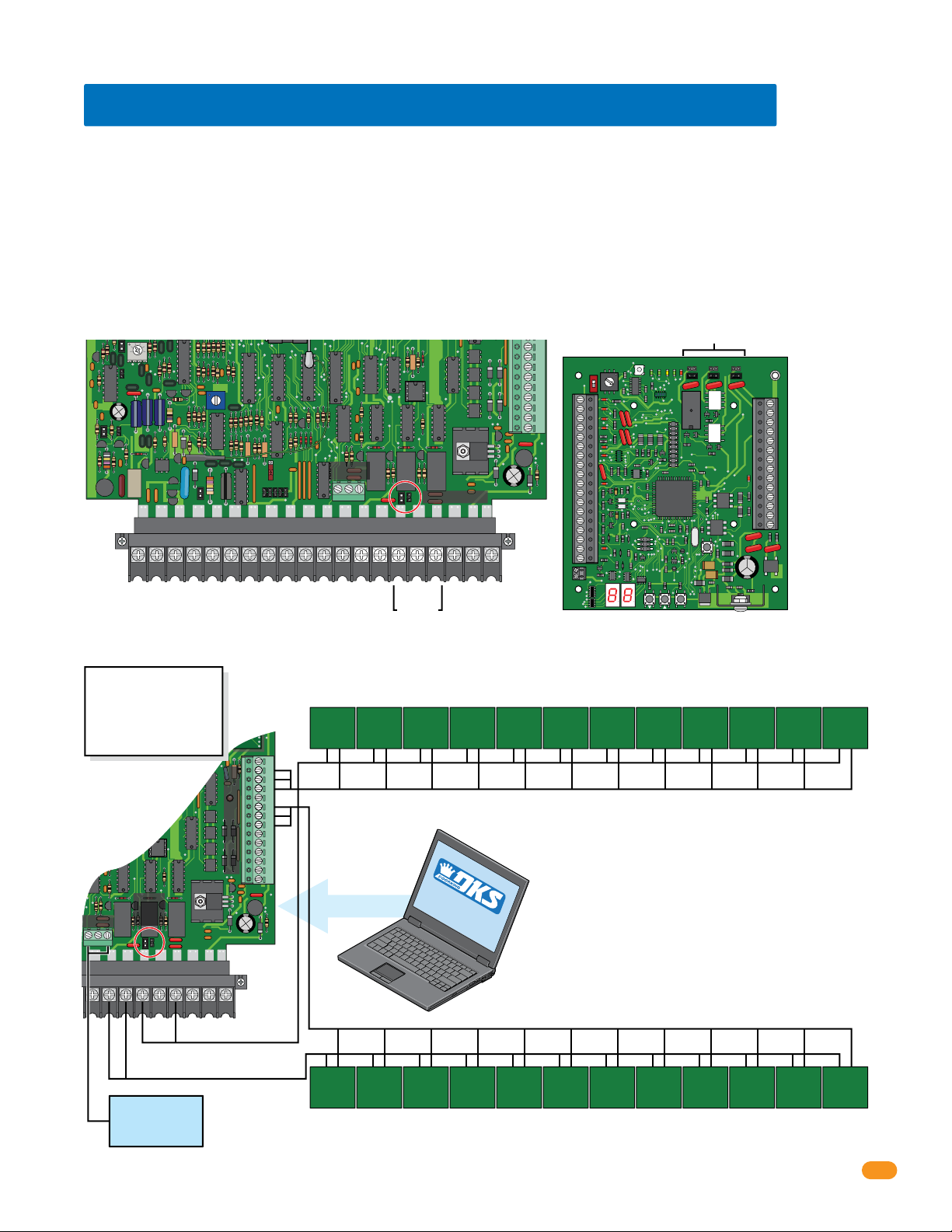
The Model 2358 Tracker Expansion Board allows you to expand the number of access points that the models 1833, 1835, 1837
and 1838 multi-door access controller PC Programmable Entry Systems can control, up to a maximum of 24. One tracker
expansion board is required for each access point. Tracker expansion boards will interface with a variety of wiegand devices
including card readers, RF transmitters, digital keypads, etc. The tracker expansion board will also report gate operator data
from DoorKing intelligent gate operators that have Gate Tracker outputs. In addition to these features, the tracker expansion
boards can also monitor the status of a door, report door ajar and forced entry conditions, sound local alarms, activate a
building alarm system, and has request to exit inputs.
Prior to beginning the installation, we suggest that you become familiar with the instructions, illustrations, and wiring
guidelines in this manual. This will help insure that your installation is performed in an efficient and professional manner.
The proper installation is an extremely important and integral part of the overall access control system. Check all local building
ordinances and building codes prior to installion. Be sure your installation is in compliance with local codes.
IMPORTANT Wireless installation of the access control system and tracker expansion boards will vary
from the HARDwire installation illustrated in this manual, see the instructions in the wireless kits for
wireless installation.
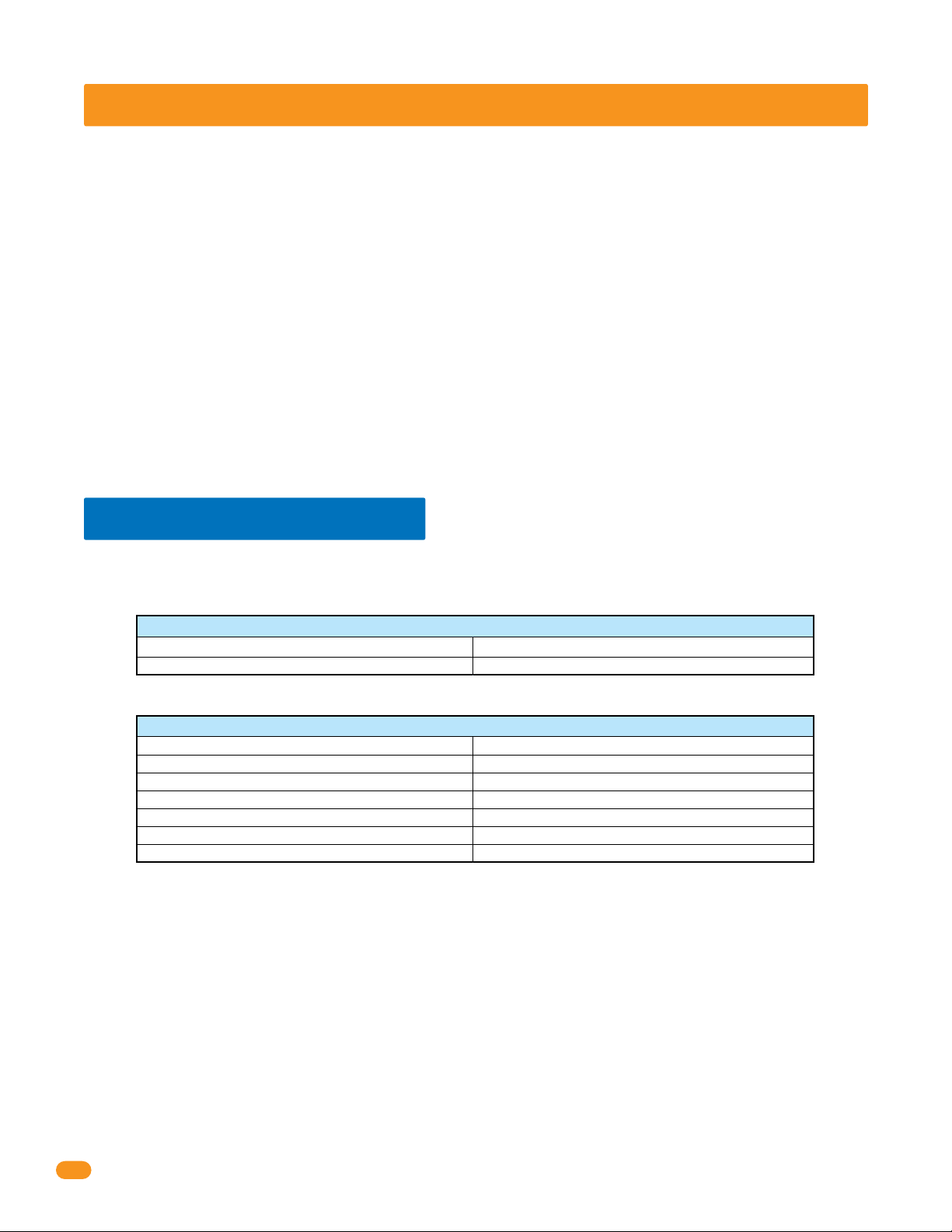
1.1 General Information
To utilize the tracker expansion board(s), DoorKing Remote Account Manager for Windows software, V 5.3 or higher is required to be
installed on the user supplied PC. The chart below is to assist you in determining if you have the proper access control system and gate
operators to utilize the tracker expansion board.
Access Control Systems
Model Control Board
1833, 1835, 1837, *1838
* 1838 Multi-Door Access Controller ONLY. NOT for use with 1838 Access Plus.
183x-010 Series
Gate Operators
Model
1601, 1602, 1603 Barrier
1150 Overhead
9200, 9500 Slide
6500 Swing, 9000 Slide
6050, 6100, 6300 Swing
9100, 9150 Slide
• Expands the control capability of selected DoorKing access control systems to manage up to 24 additional access points.
• Provides power and wiegand inputs for almost any wiegand access control device (Card reader, RF receiver, digital keypad etc.). Board
may power two card readers in parallel if required. For example: an entry and exit card reader on a single door.
• Can be used to provide a variety of door monitoring functions, such as sounding an alarm, or activating a building alarm system when
the door is forced or held open.
• Provides a request to exit input (free exit).
• Provides three programmable relay outputs.
• Hold Open Feature unlocks individual doors (or holds open individual gates) when commanded from the system software.
• Monitors transactions from DoorKing intelligent gate operators. Can monitor slide, swing or overhead gate operators and the
parking gate operator (barrier) in PAMS type applications.
• Optional Wireless kit available to connect tracker expansion board(s) to an access control system wirelessly. Maximum distances
between the access control system and tracker expansion boards will vary from the HARD wire run distances illustrated in this manual,
see the instruction manuals with the wireless kits for the correct distances between the hardware.
Control Board
1601-010
4402-010
4404-010
4405-010
4502-010
4602-010
2
2358-065-L-7-16
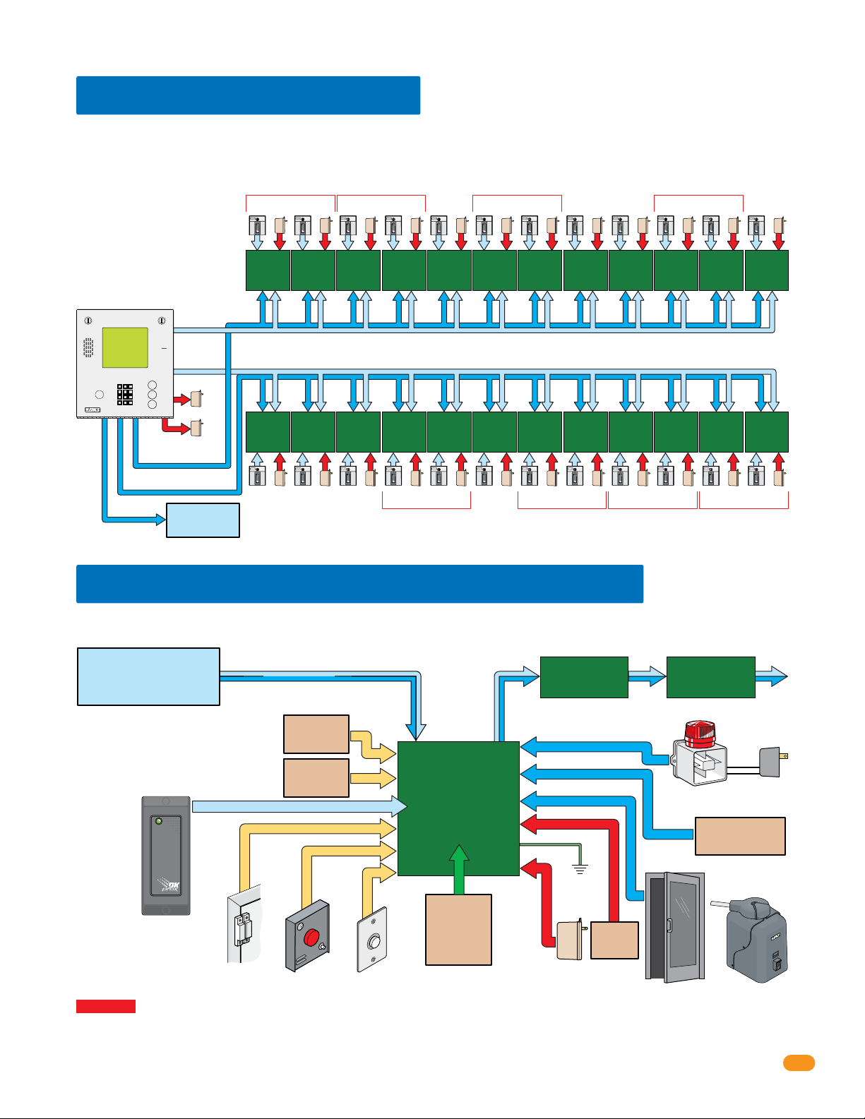
1.2 General System Layout
The diagram below shows the maximum number of tracker expansion boards that can be connected to the 1833, 1835,1837 and 1838.
Note: Wiegand 1 will activate Relay 1 and Wiegand 2 will activate Relay 2 at the access control system.
Each board can be individually
setup for each access point
depending on what functions are
desired. See section 1.3 below for
tracker expansion board options.
Zone addresses will need to be
used when using more than 8
boards per Relay/Wiegand input
(See page 6).
Access Control
System
Wiegand 1
Access
Control
Device
Expansion
access point
Address 11
12 Boards maximum for Relay 1/Wiegand 1 ONLY using board addresses 11-18
Zone Address Zone Address Zone Address Zone Address
Tracker
Board at
Board
Power
Access
Control
Device
Power
Tracker
Expansion
Board at
access point
Board
Address 11
Access
Control
Device
Tracker
Expansion
Board at
access point
Board
Address 12
Power
Access
Control
Device
Tracker
Expansion
Board at
access point
Board
Address 12
Power
Access
Control
Device
Tracker
Expansion
Board at
access point
Board
Address 13
Power
Access
Control
Device
Tracker
Expansion
Board at
access point
Board
Address 14
Power
Access
Control
Device
Tracker
Expansion
Board at
access point
Board
Address 14
Power
Access
Control
Device
Tracker
Expansion
Board at
access point
Board
Address 15
Power
Access
Control
Device
Tracker
Expansion
Board at
access point
Board
Address 16
Power
Access
Control
Device
Tracker
Expansion
Board at
access point
Board
Address 17
Power
Access
Control
Device
Power
Tracker
Expansion
Board at
access point
Board
Address 17
Access
Control
Device
Tracker
Expansion
Board at
access point
Board
Address 18
Power
Communication lines (Relay 2/Wiegand 2 AND Relay 1/Wiegand 1)
Tracker
Expansion
Board at
access point
Board
Address 4
Access
Control
Device
12 Boards maximum for Relay 2/Wiegand 2 ONLY using board addresses 3-10
Power
Tracker
Expansion
Board at
access point
Board
Address 5
Access
Control
Device
Power
Tracker
Expansion
Board at
access point
Board
Address 6
Access
Power
Control
Device
Zone Address
Tracker
Expansion
Board at
access point
Board
Address 6
Access
Control
Device
Power
Tracker
Expansion
Board at
access point
Board
Address 7
Access
Control
Device
Power
Tracker
Expansion
Board at
access point
Board
Address 8
Access
Control
Device
Power
Tracker
Expansion
Board at
access point
Board
Address 8
Access
Control
Device
Power
Tracker
Expansion
Board at
access point
Board
Address 9
Access
Control
Device
Power
Tracker
Expansion
Board at
access point
Board
Address 9
Access
Control
Device
Power
Zone Address Zone Address Zone Address
Tracker
Expansion
Board at
access point
Board
Address 10
Access
Control
Device
Power
Tracker
Expansion
Board at
access point
Board
Address 10
Access
Control
Device
Relay 0
A
Z
CALL
Wiegand 2
Power
Power
Relay 1
Relay 2
Door/Gate
Main
Tracker
Expansion
Board at
access point
Board
Address 3
Access
Control
Device
Power
1.3 Tracker Expansion Board Layout Options
The diagram below shows the connections needed when all options (gate operator data, alarm outputs, door and reset switches, request to
exit, etc.) available with the 2358 tracker expansion board are utilized at an access point.
Access Control System
Relay 1/Wiegand 1
or
Relay 2/Wiegand 2
Gate operator 1 data input:
DoorKing slide, swing or overhead
DoorKing barrier gate operator only.
Note: If card
reader has
additional
lighting for
outdoor use,
separate power
must be
provided.
Gate operator 2 data input:
Communication Line
Gate
operators only.
Operator 1
Data Input
Gate
Operator 2
Data Input
Optional Reader LED / Beeper Control
Tracker
Expansion
Board
2358-010
Next
Tracker Expansion
Board (Optional)
Auxiliary Relay
Alarm Relay
Output Relay
Ground
(Required)
12 GA. Wire
Local Alarm
Wireless Kit
Card Reader
Access Control Device
Tracker expansion board
input will accept most
wiegand 26, 30, 31-bit
access control devices.
Door Contact
Switch
Alarm
Reset
PUSH TO
EXIT
Request
to Exit
(Optional)
See Wireless
Instruction
Sheets
Board Power
16.5 VAC, 20 VA
Battery
Back-Up
(Optional)
Door Lock Gate Operator
WARNING If the access control system is used to control a vehicular gate with an automatic gate operator, the access control device
must be mounted a minimum of six (6) feet away from the gate and gate operator, ten (10) feet recommended, or in such a way that a
person cannot operate the access control device and touch the gate or gate operator at the same time.
Next
Tracker Expansion
Board (Optional)
Alarm Power
Alarm system outputs
are dry relay contacts.
Existing
Alarm System
OR
Separate
Power
2358-065-L-7-16
3
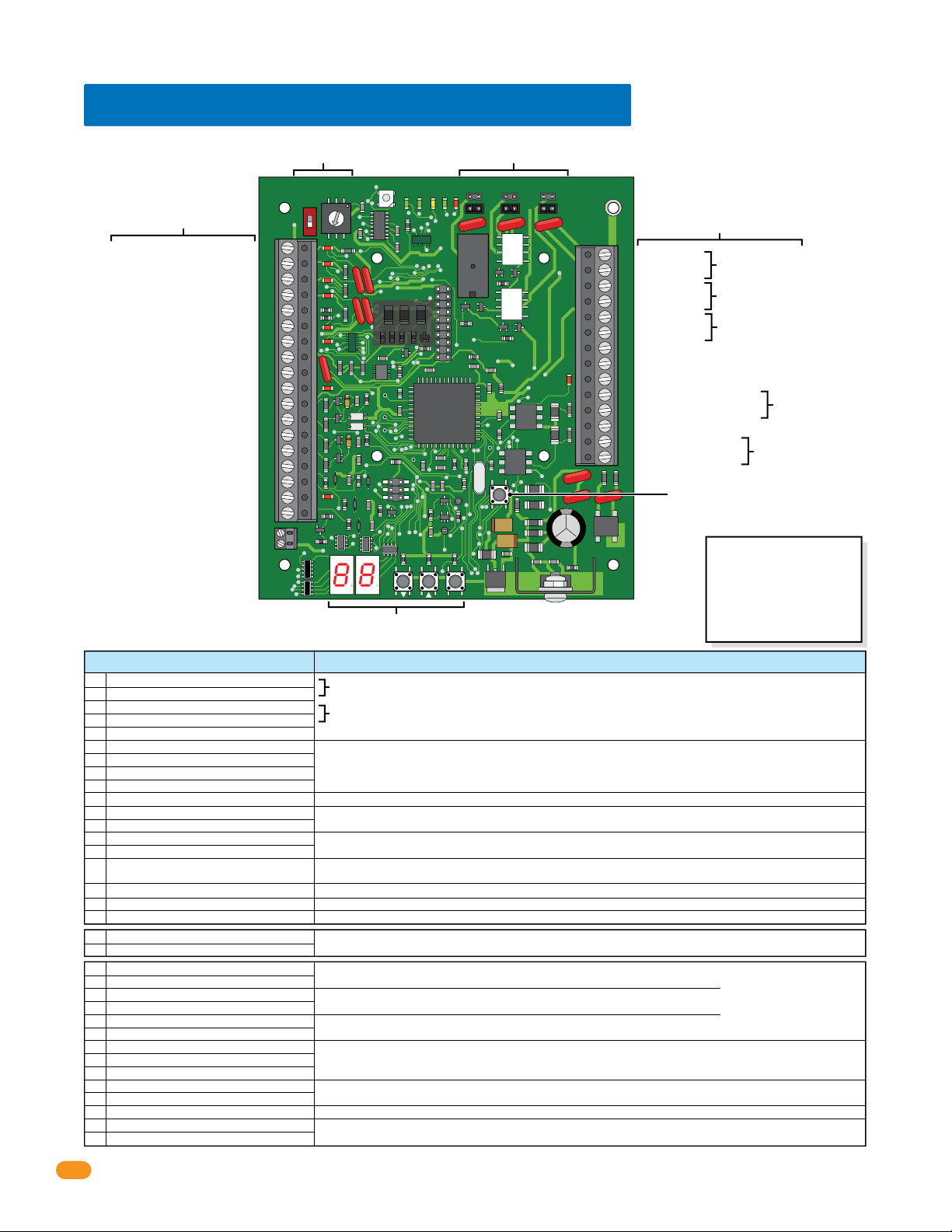
1.4 Tracker Expansion Board Overview
Board Address (System Relays)
Board Inputs
See below and next page.
1 Gate Operator 1 – Data IN
Gate Operator 1 – Busy
Gate Operator 2 – Data IN
Gate Operator 2 – Busy
Gate Operator 1 & 2 – Common
Wiegand Input – Data 0
Wiegand Input – Data 1
Wiegand Common
12 VDC Wiegand Device Power
Tracker Expansion Board Busy
Gate Operator 1 Power Monitor
Gate Operator 1 Power Monitor
Gate Operator 2 Power Monitor
Gate Operator 2 Power Monitor
Door Ajar Input
Reset Alarm Input
Communication Relay Input
Request To Exit input
Common
Card Reader LED/Beeper Control
Italic Text Note:
6-wire Communication line
REQUIRED connections.
See sections 3.2 thru 3.10.
Board Inputs Function / Connection
1
Gate Operator 1 – Data IN
2
Gate Operator 1 – Busy
3
Gate Operator 2 – Data IN
4
Gate Operator 2 – Busy
5
Gate Operator 1 & 2 – Common
6
Wiegand Input – Data 0
7
Wiegand Input – Data 1
8
Wiegand Common
9
12 VDC Wiegand Device Power
10
Tracker Expansion Board Busy
11
Gate Operator 1 Power Monitor
12
Gate Operator 1 Power Monitor
13
Gate Operator 2 Power Monitor
14
Gate Operator 2 Power Monitor
15
Door Ajar Input
16
Reset Alarm Input
17
Communication Relay Input
18
Request To Exit input
Common
19
Card Reader LED/Beeper Control
20
21
Auxiliary Relay
22
Auxiliary Relay
23
Alarm Relay
24
Alarm Relay
25
Output Relay
26
Output Relay
27
Communication Data Output – Common
28
Communication Data Output – Data 1
29
Communication Data Output – Data 0
30
Battery Negative (-12VDC)
31
Battery Positive (+12VDC)
32
Earth Ground
33
16.5 VAC Input Power
34
16.5 VAC Input Power
See pages 6 and 7.
BOARD ADDRESS
ON
1
6
5
0
1
2
3
4
5
6
7
8
9
10
11
12
13
14
15
16
17
18
19
20
26, 30, 31-bit wiegand access device input ONLY. 500 ft max.
Communication ONLY to other tracker expansion boards. DO NOT connect to access control system.
Monitors 24V AC/DC power from DoorKing slide, swing or overhead gate operators. Wire polarity does NOT matter.
Monitors 24V AC/DC power from DoorKing barrier gate operator. Wire polarity does NOT matter.
Magnetic Door Contact Switch:
Normally Closed: Switch contacts are held OPEN when the door is closed; switch contacts are CLOSED when the door is open.
Connects to a alarm reset button.
Communication to the access control system Relay 1 or 2 (Main Terminal) or other tracker expansion boards.
Connects to a request to exit button.
Connects to a card reader with LED and beeper indicators. (Available on certain card readers)
Connects to a local alarm.
Set relay to normally OPEN (NO) or normally CLOSED (NC) using relay jumpers on board.
Connects to an existing building alarm system.
Set relay to normally OPEN (NO) or normally CLOSED (NC) using relay jumpers on board.
Connects to door control (electric strike, maglock) or gate control (gate operator).
Set relay to normally OPEN (NO) or normally CLOSED (NC) using relay jumpers on board.
Communication data output to Wiegand 1 or 2 input (Auxiliary Terminal) on the access control system.
Optional battery back-up allows the tracker expansion board to maintain operation during power out conditions.
Use .8 amp gel cell for single board P/N 1801-008, 3 amp gel cell for 4 boards max. P/N 1801-009.
To an approved grounding source (Required).
Use supplied 16.5 VAC, 20 VA transformer (or UL listed equivalent) to power the tracker expansion board.
Max power wire run with 18 AWG wire is 100 feet; with 16 AWG wire is 200 feet. Wire polarity does NOT matter.
Board Relay Jumpers
See page 7.
4
7
8
2
3
9
0
1
RF
SECURE
RF
DATA
STATUS
Wireless
Connection
See wireless
instructions.
OUTPUT
ALARM
RF
CODE
CODE
CODE
RELAY
SENT
GOOD
BAD
NC
NO
RELAY
AUX
RELAY
NC
NO
2358-010
Board Outputs & Power
NC
NO
See below and next page.
21
Auxiliary Relay
22
Auxiliary Relay
23
Alarm Relay
24
Alarm Relay
25
Output Relay
26
Output Relay
27
Communication Data Output – Common
28
Communication Data Output – Data 1
29
Communication Data Output – Data 0
30
Battery Negative (-12VDC)
31
Battery Positive (+12VDC)
32
Earth Ground
33
16.5 VAC Input Power
34
16.5 VAC Input Power
Reset Button
RESET
ENT
Press to reset the board.
Programming
See section 4.
Gate operator 1 data input from DoorKing slide, swing or overhead gate operators.
Gate operator 2 data input from DoorKing barrier gate operator.
Set relay jumper.
Set relay jumper.
Set relay jumper.
Battery
Back-Up
Power
Transformer
Important Wireless Note:
Wireless kits DO NOT use the
#10, #17, #19, #27, #28 and
#29 communication line. Refer
to wireless instructions with
the wireless kits when using
wireless communication.
Note: Relay
contacts are
rated at 1A 30V
maximum.
4
2358-065-L-7-16

A
A
1.5 Board Input Descriptions
ccess Control Device Input (26, 30, 31-Bit Wiegand)
Tracker expansion boards can accept wiegand input data from most devices that output their data in a wiegand format. When using 30 or
31-bit wiegand devices, the system will only recognize facility code 255 and lower. An access control device (a card reader for example) is
connected to the tracker expansion board (Terminals 6-7-8-9). When the tracker expansion board receives the wiegand data from the access
device, it sends the data to the access control system where the decision to grant or deny access is made. At the same time, a report is made
of this activity and is stored in the transaction buffer. Two access control devices may be connected to a single tracker expansion board,
however each device will report the same location in the transaction report when connected in this method and each device will activate the
same door (or gate). This may be preferable in some instances. For example, if a vehicular gate uses both a card reader and an RF receiver for
resident access, each of these devices can be connected in parallel. Each device will activate the gate (door) that the output relay of the tracker
expansion board is connected to, and each device will appear in the transaction report with the name assigned to the tracker expansion board
in the software (“Main Gate”, for example, Refer to the Dual Door Mode ).
Gate Operator Data Input
Gate operator data inputs can only be used with DoorKing vehicular gate operators (see section 1.1). The tracker expansion board receives data
(Terminals 1-5 and 11-14) from the gate operator control board, converts it to wiegand format, and then sends this wiegand data to the access
control system where it is stored in the transaction buffer. The data that is sent from the gate operator control board includes information such as
gate operator cycle count (x100), if an obstruction was hit, if an attempt was made to force the gate, etc. See the back of manual for a complete
listing of all gate operator transactions. In PAMS applications, only one tracker expansion board is required per traffic lane to monitor the gate
operator activity of the slide, swing or overhead gate operator, and the parking gate operator. The tracker expansion board will also monitor the 24
VAC power from the gate operator control board(s). When this power is removed, a “power out” transaction is sent to the access control system.
Request to Exit Input
An alarm condition will exist anytime a controlled door is opened without access being granted by the access control system. The request to exit
input (Terminals 18 & 19) allows the door to be opened without activating the tracker expansion board alarm relays, and will not cause the
access system to report a forced condition. The request to exit is typically used at a controlled access point to allow free exit to personnel. A
“Push To Open” button, or a push bar, etc., is connected to the request to exit input on the tracker expansion board. When this input is activated,
the tracker expansion board
output relay
will activate causing the door strike or magnetic lock to release allowing the door to be opened.
Door Ajar Input
The door ajar input (Terminals 8 & 15) monitors the status of a controlled access door through a magnetic (typical) door contact switch. This
input tells the tracker expansion board if the door is not fully closed, and will cause the alarm and auxiliary relays on the tracker expansion
board to activate under certain conditions (see section 3 and section 4). Typically, when the door is closed, the switch contacts are closed;
when the door is open, the switch contacts are open.
Reset Alarm Input
The reset alarm input (Terminals 16 & 19) overrides the door ajar input allowing a door to be held open when necessary. When this input is
activated, the tracker expansion board will not activate its alarm or auxiliary relays even if the door ajar input is activated (see section 4).
Communication Relay Input
The relay input (Terminals 17 & 19) is connected to the Relay 1 or Relay 2 in the access control system that activates when a valid device
code is received by the access control system. For example, when a card reader connected to the wiegand input on the tracker expansion
board reads the card code, it inputs this information to the tracker expansion board, which in turn sends the information to the access control
system. The access control system then makes the decision to grant or deny access. If access is denied, a transaction of the denial is made
and nothing else happens. If access is granted, a transaction of the access grant is made, and the access control system activates the
communication relay. This relay output is connected to the tracker expansion board system communication relay input, which then causes the
tracker expansion board output relay to activate. The output relay activation will then open the controlled door (or gate). If two or more tracker
expansion boards are connected to the access system, only the output relay on the tracker expansion board that sent the data will activate.
The tracker expansion board relay strike time is set via the programming on the tracker expansion board (see section 4).
(Communication Line to Access Control System’s Main Terminal Relay 1 or Relay 2)
uxiliary and Alarm Relays
Activation and operation of the AUXILIARY (Terminals 21-22) and ALARM (Terminals 23-24) relays is dependent on the programming on the tracker
expansion board (see section 4). Typically, the auxiliary relay is connected to a local alarm (bell, buzzer, light, etc.) and the alarm relay is connected to
the buildings existing alarm system. These relays provide a dry contact only.
Output Relay
The
Output Relay
releases the door strike (or magnetic lock) to allow entry or exit, or activates a gate operator if the tracker expansion board is used to control a
vehicular gate.
(Terminals 25-26) activates on command from the access control system, or from a request to exit input. The
This relay provides a dry contact only.
output relay
Communication Data Output
All data received at the wiegand input terminals and the gate tracker terminals is sent to the access control system in 26, 30, 31-bit wiegand
format from the wiegand output (Terminals 27-28-29).
2358-065-L-7-16
(Communication Line to Access Control System’s Auxiliary Terminal Wiegand 1 or Wiegand 2)
5
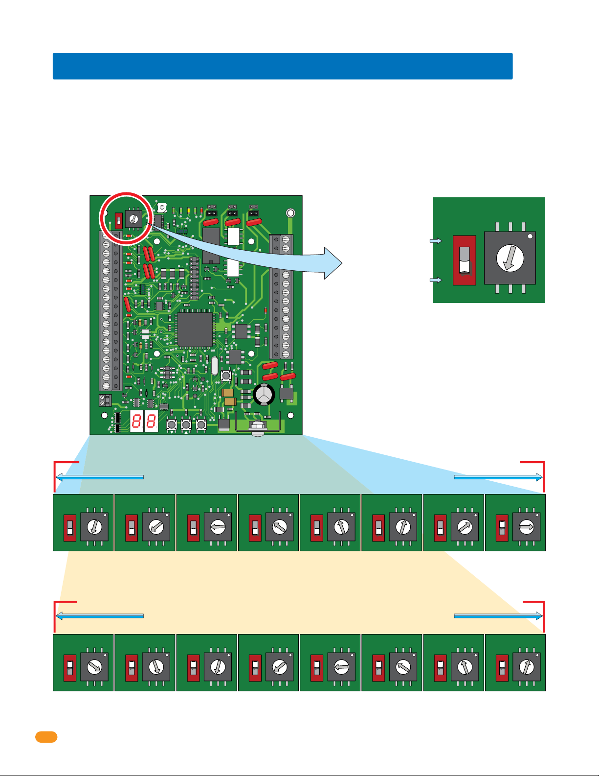
1.6 Setting Board Address (Software - System Relay)
When using tracker expansion boards connected to a single access control system, the board addresses on EACH tracker expansion board
should be set so that the Remote Account Manager for Windows (V 5.0 or higher only) software can identify each tracker expansion
board. The software reserves board address 0, 1 and 2 for the access control system. Tracker expansion board address starts with relay
address 3 (see below). IMPORTANT: The software uses the board address number for the System Relay number.
“Zone” Addresses: Board addresses can be set the same (functions as “zones”), but the system’s “tracking” capability will NOT be able to
distinguish SPECIFIC access point activity. Two or more boards with the same board address will be tracked and logged as “zone number”
but not a specific location for that activity. For example, if you have 4 card readers in different locations in a building, and all have the same
board addresses, the software would track that a card reader in the “zone number” was used, but not which specific location it was used.
Zones can be used for a restricted area with multiple entrances inside the complex such as a pool area/tennis courts or community center.
Zones are not recommended if detailed tracker activity reports are required.
1
2
3
4
5
6
7
8
9
10
11
12
13
14
15
16
17
18
19
20
BOARD ADDRESS
ON
8
7
1
6
5
4
3
0
RF
SECURE
RF
DATA
9
0
1
2
OUTPUT
ALARM
RF
CODE
CODE
CODE
STATUS
RELAY
SENT
GOOD
BAD
NC
NO
RELAY
AUX
RELAY
NC
NO
2358-010
BOARD ADDRESS
NC
NO
ON
8
7
9
6
5
0
1
4
2
3
Dial Numbers
RESET
21
22
23
24
25
26
27
28
29
30
31
32
33
IMPORTANT: DO NOT
34
set the board address
to 0, 1, 2 or 19.
Switch MUST be ON (1) for
board addresses 10 thru 18.
(Dial number +10).
Switch MUST be OFF (0) for
board addresses 3 thru 9.
(Dial number only).
1
0
OFF
Switch
Set dial numbers
accordingly with switch.
Example: The switch is OFF and
the dial is set to 3, so the Board
Address is 3. The software uses
the board address as the System
Relay, this means the System
Relay for this board is 3. See
below for all board settings.
ENT
Board addresses 3 thru 10 MUST connect to Relay 2/Wiegand 2 on the access control system
Maximum HARD wire run between tracker expansion boards (up to 12 boards) is 4000 feet TOTAL,
BOARD ADDRESS
ON
1
6
5
0
OFF
Board Address 3
System Relay 3
8
7
9
0
1
4
2
3
BOARD ADDRESS
1
0
ON
OFF
8
7
9
6
0
5
1
4
2
3
Board Address 4
System Relay 4
Note: Start at board address 3, the software reserves board address (system relay) 0, 1 and 2 for the access control system ONLY.
see section 2 for more information about HARDwiring limitations.
BOARD ADDRESS
ON
1
6
5
0
OFF
Board Address 5
System Relay 5
8
7
9
0
1
4
2
3
BOARD ADDRESS
1
0
ON
OFF
8
7
9
6
0
5
1
4
2
3
Board Address 6
System Relay 6
BOARD ADDRESS
1
0
ON
OFF
8
7
9
6
5
1
4
2
3
Board Address 7
System Relay 7
0
BOARD ADDRESS
1
0
ON
OFF
8
7
9
6
5
1
4
2
3
Board Address 8
System Relay 8
BOARD ADDRESS
ON
1
0
0
OFF
Board Address 9
System Relay 9
7
6
5
4
3
Board addresses 11 thru 18 MUST connect to Relay 1/Wiegand 1 on the access control system
BOARD ADDRESS
1
0
ON
OFF
8
7
9
6
5
1
4
2
3
Board Address 11
System Relay 11
BOARD ADDRESS
ON
1
0
0
OFF
Board Address 12
System Relay 12
Maximum HARD wire run between tracker expansion boards (up to 12 boards) is 4000 feet TOTAL,
8
7
9
6
0
5
1
4
2
3
see section 2 for more information about HARDwiring limitations.
BOARD ADDRESS
ON
1
6
5
0
OFF
Board Address 13
System Relay 13
8
7
9
0
1
4
2
3
BOARD ADDRESS
1
0
ON
OFF
8
7
9
6
0
5
1
4
2
3
Board Address 14
System Relay 14
BOARD ADDRESS
1
0
ON
OFF
8
7
9
6
0
5
1
4
2
3
Board Address 15
System Relay 15
Note: Board Addresses 0, 1, 2 & 19 will not generate a wiegand signal.
BOARD ADDRESS
1
0
ON
OFF
8
7
9
6
0
5
1
4
2
3
Board Address 16
System Relay 16
BOARD ADDRESS
ON
OFF
7
6
5
4
3
1
0
Board Address 17
System Relay 17
BOARD ADDRESS
8
9
1
0
1
2
0
Board Address 10
System Relay 10
BOARD ADDRESS
8
9
1
0
1
2
0
Board Address 18
System Relay 18
ON
OFF
ON
OFF
8
7
9
6
0
5
1
4
2
3
8
7
9
6
0
5
1
4
2
3
6
2358-065-L-7-16
RS 232
1
2
3
4
1.7 Relay Identification (Software - System Relay)
5
6
The models 1833, 1835, 1837 and 1838 access control systems each have THREE relays (Relay 0, 1, and 2). When the tracker expansion
boards is added to this system, the Output Relay on the tracker expansion boards (Terminals 25-26) are identified in the software by the
board address, beginning with board address 3 = System Relay 3 (System Relays 0, 1 and 2 are reserved for the access control board
relays ONLY in the software).
Each of the 3 relays on the tracker expansion board can be set to either Normally Open (NO) or Normally Closed (NC) by setting the board
ELEVATOR
1
2
3
relay jumper to the desired configuration. Typically, normally OPEN is used.
When tracker expansion boards are used to expand the access control system, Relays 1 and 2 on the access control system circuit board are
used as tracker expansion communication relays. Relay 2 MUST connect to tracker expansion board addresses 3-10 (system relays 3-10)
and Relay 1 MUST connect to tracker expansion board addresses 11-18 (system relays 11-18).
If both Relay 1 and Relay 2 are used to control tracker expansion boards, Relay 0 is used as the Primary Relay that will open the main door or
gate when the resident pushes “9” on their telephone.
FEED
BACK
321
1816
HF
HS
MIC
VOL
321
321
SPK
VOL
CLK
SEN
ON
MASTER
CODE
OFF
KEYPAD
RING
Access Control System Main Terminal
5VDCIMDSPKRCOMMICPSWCGNDPHONE
Relay 0
NO NC C
Set relay 2 jumper NO or NC.
Relay 2
NO
NC
Relay 1
Relay 2 Jumper
Board Relay Jumpers
RF
BOARD ADDRESS
1
0
1
2
3
12345 67891011121314
4
5
6
7
8
9
10
11
12
13
14
15
16AC16ACBAT1NO1NC1C2RY2CAZIMC
16
17
18
19
20
SECURE
ON
8
7
9
6
0
5
1
4
2
3
OUTPUT
ALARM
RF
RF
CODE
CODE
CODE
DATA
STATUS
SENT
GOOD
BAD
ENT
AUX
RELAY
RELAY
RELAY
NC
NO
RESET
2358-010
NC
NC
NO
NO
21
Aux Relay
22
23
Alarm Relay
24
25
Output Relay
26
27
(System Relay)
28
29
30
31
32
33
34
Tracker Expansion Board
Remote Account Manager Software for Windows System Relay Identification
Important Wireless Note:
Wireless kits ARE NOT
wired like this. Refer to
wireless instructions with
the wireless kits when using
wireless communication.
Access
Control
System
Board
Relay 2
Jumper
Relay 0
NO NC C
“NO”
NO
NC
Main Terminal
Relay 2
Main Terminal
Relay 0
Main
Door/Gate
Note: Relay 2 jumper
set to normally OPEN.
16AC
16ACBAT1NO1NC1C2RY2CA
2019181612 13 14 15 17
Relay 1
Main Terminal
Auxiliary Terminal
12345 678910 11 12 13 14
ONLY Board Addresses 11-18 connect to Relay 1/Wiegand 1 (12 Boards max)
Zone Address Zone Address Zone Address Zone Address
Tracker
Expansion
Board at
access point
Address
Board
Tracker
Tracker
Board
Tracker
Expansion
Board at
access point
12
Address
Expansion
Expansion
Board at
Board
Board at
access point
11
Address
access point
11
Address
Board
Tracker
Board
Tracker
Expansion
Board at
access point
13
Address
Expansion
Board at
access point
12
Address
Board
Tracker
Expansion
Board at
access point
14
Address
Board
Tracker
Tracker
Board
Tracker
Expansion
Board at
access point
16
Address
Expansion
Expansion
Board at
Board
Board at
access point
15
Address
access point
14
Address
Board
Tracker
Expansion
Board at
access point
Board
17
Address
Wiegand 1 (Aux Terminal)
System Relays for the tracker expansion boards are
identified in the DKS software sequentially by the board
address, beginning with board address 3 = System Relay 3
SOFTWARE
RS-232
INSTALLED
Your PC connected to the access control system board
(RS-232 terminal).
Tracker
Expansion
Board at
access point
Address
Board
3
Tracker
Expansion
Board at
access point
Board
Address
Tracker
Board
Tracker
Expansion
Board at
access point
Board
5
Address
6
Expansion
Board at
access point
4
Address
ONLY Board Addresses 3-10 connect to Relay 2/Wiegand 2 (12 Boards max)
and ending with board address 18 = System Relay 18.
Relays 0, 1 and 2 are “Physically” located on the access
control board. They are identified in the DKS software as
system relays 0, 1 and 2.
Zone addresses CAN be used but MUST be used when
more than 8 boards are required for a Relay/Wiegand input.
See previous page about zone addresses.
Wiegand 2 (Aux Terminal)
Tracker
Expansion
Board at
access point
Board
Address
6
Tracker
Expansion
Board at
access point
Address
Board
Tracker
Expansion
Board at
access point
7
Address
Board
Tracker
Tracker
Board
Tracker
Expansion
Board at
access point
9
Board
Address
access point
9
Address
Expansion
Expansion
Board at
Board
Board at
access point
8
Address
access point
8
Address
Tracker
Expansion
Board at
Board
Tracker
Expansion
Board at
access point
Board
17
Address
Tracker
Expansion
Board at
access point
Board
10
Address
Zone AddressZone AddressZone AddressZone Address
18
10
2358-065-L-7-16
7
SECTION 2 - INSTALLATION
The location of the tracker expansion board(s) is dependent on the application that it is being used. Tracker expansion boards
can be installed in selected card reader housings, or they can be installed in their own enclosure (enclosures are optional and
not included with the tracker expansion board). DoorKing has two enclosures available for this purpose. The small housing will
hold a single tracker expansion board and the large housing can hold up to four tracker expansion boards. In addition, the large
housing has convenience outlets to power up to four accessory transformers.
Selected models of proximity card readers are available with an enclosure that has ample room for a tracker expansion board to
be mounted inside the housing. This simplifies the installation of the card reader used with the tracker expansion board.
IMPORTANT Wireless communication maximum distances between the access control system and tracker expansion
boards will vary from the HARDwire run distances illustrated below. See the instruction sheets in the wireless kits and the
Layout and Start-Up Procedure for the correct distances between the hardware when using wireless communication.
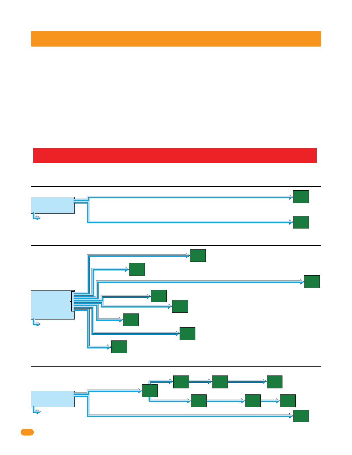
HARDwire Run: Up to 12 tracker expansion boards can be wired to EACH of the TWO communication
lines available (relay 2/wiegand 2 and relay 1/wiegand 1) at the access control system.
IMPORTANT: The maximum distance for a tracker expansion board HARDwire run is 4000 feet TOTAL (1 to 12 boards
can be in a HARDwire run). The farthest boards can be NO more than 2000 feet away from the access control system.
Example 1: 4000 ft total, ONLY one HARDwired communication line shown. 2 boards are connected to relay 2/wiegand 2.
farthest
access control system
relay 2/wiegand 2
relay 1/wiegand 1
A second communication
line can be wired with the
same wiring limitations shown in examples if desired.
Communication line to boards are
connected in parallel. Allows “teeing”
of communication cable for optimal
cable routing.
2000 ft
NO more boards can be connected to reley 2/wiegand 2 communication line.
2000 ft
Zone addresses can be used if desired.
tracker
expansion
board
address 3
tracker
expansion
board
address 4
board
2000 ft
away
farthest
board
2000 ft
away
Example 2: 4000 ft total, ONLY one HARDwired communication line shown. 8 boards are connected to relay 2/wiegand 2.
tracker
expansion
board
address 3
All boards are less than 2000 ft away from access control system.
1900 ft
Communication line to boards are connected
in parallel. Allows “teeing” of communication
cable for optimal cable routing.
tracker
expansion
board
address 9
Relay 1/wiegand 1 connects to tracker expansion board
addresses 11 thru 18 if that many boards are desired.
Relay 2/wiegand 2 MUST be connected to tracker
expansion board addresses 3 thru 10.
access control system
relay 2/wiegand 2
relay 1/wiegand 1
A second communication
line can be added with same
wiring limitations shown in
examples if desired.
100 ft
200 ft
150 ft
tracker
expansion
board
address 10
expansion
address 4
300 ft
400 ft
tracker
expansion
board
address 8
500 ft
tracker
board
tracker
expansion
board
address 6
450 ft
Zone addresses can be used if desired.
tracker
expansion
board
address 7
Example 3: 4000 ft total, ONLY one HARDwired communication line shown. 8 boards are connected to relay 2/wiegand 2.
Zone addresses can be used if desired.
tracker
expansion
board
address 5
tracker
expansion
board
address 7
500 ft
2000 ft
200 ft
tracker
expansion
address 8
board
expansion
address 6
100 ft
tracker
board
access control system
relay 2/wiegand 2
relay 1/wiegand 1
A second communication
line can be added with the
same wiring limitations shown in examples if desired.
Communication line to boards are
connected in parallel. Allows “teeing”
of communication cable for optimal
cable routing.
500 ft
100 ft 100 ft
tracker
expansion
board
address 3
500 ft
tracker
expansion
board
address 4
tracker
expansion
board
address 5
Relay/Wiegand Note:
farthest board
900 ft away
farthest
tracker
board
expansion
1600 ft
board
away
address 9
tracker
farthest
expansion
board
board
2000 ft
address 10
away
8
2358-065-L-7-16
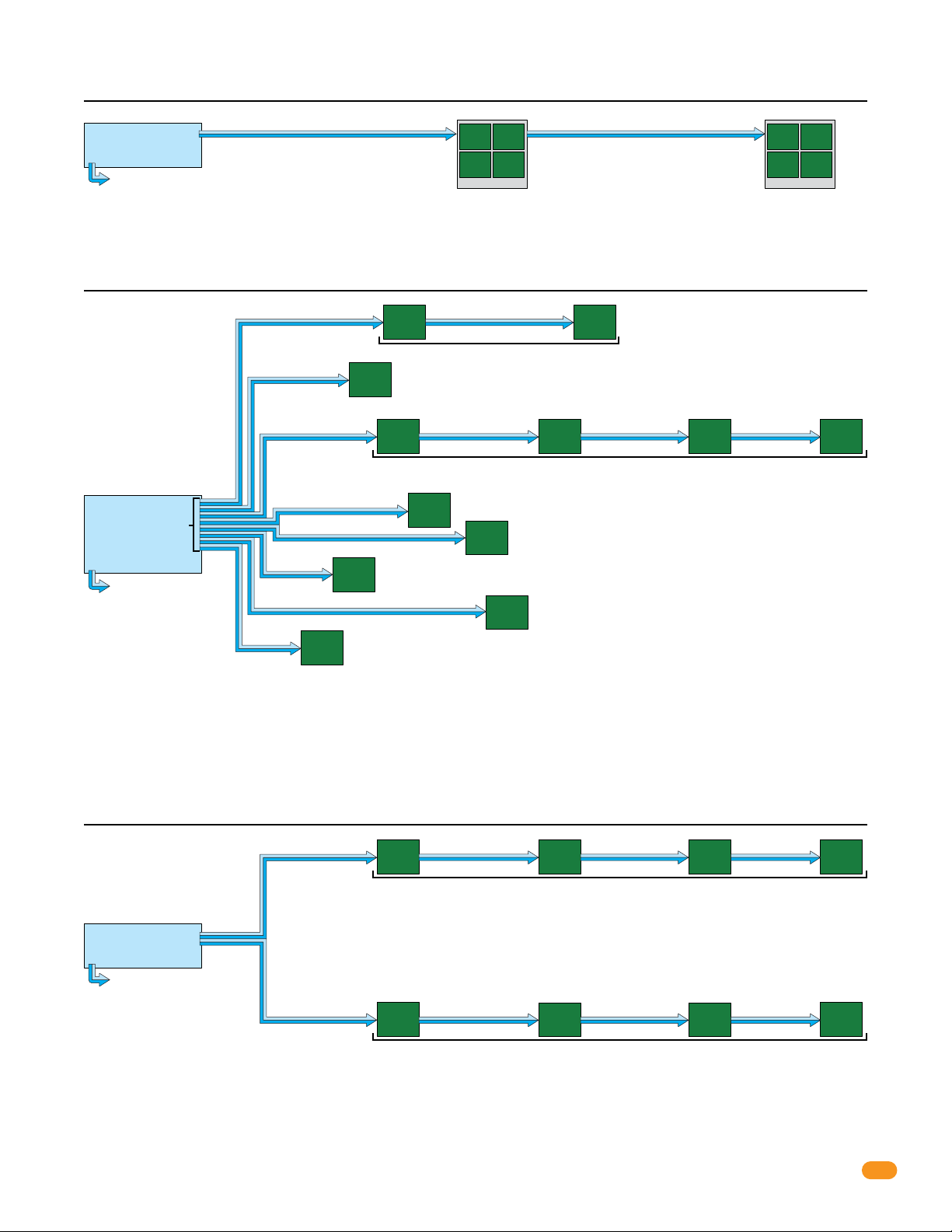
Example 4: 2000 ft total, ONLY one HARDwired communication line shown. 8 boards are connected to relay 2/wiegand 2.
access control system
relay 2/wiegand 2
relay 1/wiegand 1
A second communication line can be added with same
wiring limitations shown in examples if desired.
1000 ft
tracker
expansion
board
address 3
tracker
expansion
board
address 5
Quad Box
tracker
expansion
board
address 4
tracker
expansion
board
address 6
1000 ft
Zone addresses can be used if desired.
tracker
expansion
board
address 7
tracker
expansion
board
address 9
Quad Box
tracker
expansion
board
address 8
tracker
expansion
board
address 10
farthest
board
2000 ft
away
Example 5: 4000 ft total, ONLY one HARDwired communication line shown. 12 boards maximum with “Zones” are connected to relay 2/wiegand 2.
250 ft 250 ft
tracker
expansion
board
address 3
Zone Addresses
200 ft
tracker
expansion
board
address 4
tracker
expansion
board
address 3
All boards are less than 2000 ft away from access control system.
tracker
400 ft
tracker
board
450 ft
expansion
board
address 5
tracker
expansion
board
address 6
tracker
expansion
board
address 7
expansion
address 9
tracker
expansion
address 5
Communication line to boards are connected
in parallel. Allows “teeing” of communication
cable for optimal cable routing.
board
Wiring More Than 8 Boards Note:
Use 6 conductor stranded with overall shield - 18 gauge.
access control system
relay 2/wiegand 2
relay 1/wiegand 1
A second communication
line can be added with same
wiring limitations shown in
examples if desired.
100 ft
500 ft 600 ft 400 ft 400 ft
300 ft
150 ft
tracker
expansion
board
address 10
expansion
address 8
ONLY use 18 gauge when wiring more than 8 boards.
DO NOT connect shield to 2358-010 board common.
DO NOT use twisted pair.
Example 6: 4000 ft total, ONLY one HARDwired communication line shown. 8 boards
tracker
expansion
board
address 3
tracker
expansion
board
address 4
expansion
address 3
Individual addresses can be used if desired.
NO more boards can be connected to reley 2/wiegand 2 communication line.
expansion
address 4
Individual addresses can be used if desired.
access control system
relay 2/wiegand 2
relay 1/wiegand 1
A second communication
line can be wired with the
same wiring limitations shown
in examples if desired.
500 ft 600 ft 400 ft 500 ft
Communication line to boards are connected in
parallel. Allows “teeing” of communication cable
for optimal cable routing.
500 ft 600 ft 400 ft 500 ft
tracker
board
Zone Addresses
Relay 1/wiegand 1 connects to tracker expansion board
with “Zones”
tracker
board
Zone Addresses
tracker
board
Zone Addresses
tracker
expansion
board
address 5
tracker
expansion
board
address 5
farthest
board
1900 ft
away
Relay/Wiegand Note:
Relay 2/wiegand 2 MUST be connected to tracker
expansion board addresses 3 thru 10.
addresses 11 thru 18 if that many boards are desired.
are connected to relay 2/wiegand 2.
tracker
expansion
board
address 3
tracker
expansion
board
address 4
tracker
expansion
board
address 3
farthest
board
2000 ft
away
tracker
expansion
board
address 4
farthest
board
2000 ft
away
IMPORTANT Wireless communication maximum distances between the access control system and tracker expansion
boards will vary from the HARDwire run distances illustrated above. See the instruction sheets in the wireless kits and the
Layout and Start-Up Procedure for the correct distances between the hardware when using wireless communication.
2358-065-L-7-16
9
 Loading...