


Owner’s Manual
1819 Information Phone
DoorKing, Inc.
120 Glasgow Avenue
Inglewood, California 90301
U.S.A.
Phone: 310-645-0023
Fax: 310-641-1586
www.doorking.com
P/N 1819-065 REV B, 4/07
Copyright 2007 DoorKing, Inc. All rights reserved.

1819-065-B-4-07
Page 2

1819-065-B-4-07
Use this manual with the following models only.
1819 Information Telephone with circuit board 1862-010, Rev I or higher.
DoorKing, Inc. reserves the right to make changes in the products described in this manual
without notice and without obligation of DoorKing, Inc. to notify any persons of any such revisions
or changes. Additionally, DoorKing, Inc. makes no representations or warranties with respect to
this manual. This manual is copyrighted, all rights reserved. No portion of this manual may be
copied, reproduced, translated, or reduced to any electronic medium without prior written consent
from DoorKing, Inc.
Page 3

1819-065-B-4-07
Page 4

1819-065-B-4-07
QUICK START
Mount the Telephone Entry S y s tem. If the unit is being used to provide access through an
1
2
3
automated vehicular gate, the unit must be mounted at least 10-feet away from the gate.
See pages 11-13.
Connect 16 VAC power to term inals 13-14. Connect a dedicated touch-tone lo op- start
phone line to terminals 1- 2. Connect ground wire to terminal 3.
See pages 15-18.
Connect device(s) t o be a ctivated (gate operator, door strikes, etc.) to relay terminals as
required.
See pages 17-18.
4
5
6
Program a MASTER CODE ( Section 3.1.1) - Factory Default is 9999
1. Open the cabinet and turn the Master Code switch ON.
2. Enter a four-digit M as ter Code on the keypad and then press *.
3. Turn the Master Code switch OFF.
Program Phone Number ( Section 3.2.1)
1. Press *01 and enter Master Code.
2. Enter 001 then press *.
3. Enter a 7-digit Phone Numbe r t hen press *.
4. Press 0# TOGETHER when fi nished.
Adjustments ( Se ction 2.4)
1. Make a phone call.
2. Adjust microphone volum e**, speaker volume and feedback.
3. Have tenant press 9 to open door or gate.
** Rev H boards and higher only.
Page 5

1819-065-B-4-07
TABLE OF CONTENTS
Preface
Important Notices......................................................................................................................................................8
Important Information................................................................................................................................................9
Features ..................................................................................................................................................................10
Section 1 – Installation
1.1 Installation Guidelines ..............................................................................................................................11
1.2 Surface Mount..........................................................................................................................................12
1.3 Memory Chip Installation..........................................................................................................................13
Section 2 – Wiring & Adjustments
General Information..................................................................................................................................................15
2.1 Circuit Board Adjustments........................................................................................................................16
2.2 Wiring Diagram.........................................................................................................................................17
2.3 Main Terminal Description........................................................................................................................18
2.4 Adjustments
2.4.1 Speaker Volume.......................................................................................................................19
2.4.2 Microphone Volume .................................................................................................................19
2.4.3 Feedback..................................................................................................................................19
2.4.4 Click Sensitivity ........................................................................................................................19
2.4.5 Master Code Switch.................................................................................................................20
2.4.6 Ring Pin....................................................................................................................................20
Section 3 – Programming
General Information..................................................................................................................................................21
3.1 General Programming
3.1.1 Master Code.............................................................................................................................22
3.1.2 Single or Multiple Systems.......................................................................................................22
3.1.3 Relay Strike Time.....................................................................................................................22
3.1.4 Tone Open Numbers................................................................................................................23
3.1.5 Touch-tone / Rotary-dial...........................................................................................................23
3.1.6 Number of Rings to Answer .....................................................................................................23
3.1.7 System Stay On Line after Touch Tone...................................................................................24
3.1.8 Automatic Hang-up...................................................................................................................24
3.1.9 Call Button programming..........................................................................................................24
3.2 Phone Number Programming
3.2.1 7-Digit Phone Numbers............................................................................................................25
3.2.2 Area Codes ..............................................................................................................................25
3.2.3 Phone Numbers with Area Code Reference............................................................................25
3.2.4 Deleting Individual Phone Numbers.........................................................................................26
3.3 Time Functions Programming
3.3.1 Time Clock Programming.........................................................................................................27
3.3.2 Automatic Relay Activation Time Zones...................................................................................27
Page 6

1819-065-B-4-07
Section 4 – Operating Instructions
4.1 General Instructions
4.1.1 Calling Instructions...................................................................................................................29
4.1.2 Responding to a Call................................................................................................................29
4.2 System Administrator
4.2.1 Remote Programming..............................................................................................................30
4.2.2 Remote Relay Activation..........................................................................................................30
4.2.3 Relay Check.............................................................................................................................30
4.2.4 Auto Relay Activation Time Zone Enable / Disable..................................................................31
4.3 Miscellaneous Operating Instructions
4.3.1 Line Sharing.............................................................................................................................32
4.3.2 Connection to a PBX................................................................................................................32
4.3.3 10-digit Dialing .........................................................................................................................32
Section 5 – Maintenance and Trouble Shooting
5.1 Replacement Parts...................................................................................................................................33
5.2 Trouble Shooting......................................................................................................................................33
5.3 Accessories..............................................................................................................................................36
5.4 Log Tables................................................................................................................................................37
Page 7

1819-065-B-4-07
IMPORTANT NOTICE
FCC - UNITED STATES
This equipment has been tested and found to comply with the limits for a class A digital device,
pursuant to Part 15 of the FCC Rules and Regulations. These limits are designed to provide
reasonable protection against harmful interference when the equipment is operated in a commercial
environment. This equipment generates, uses, and can radiate radio frequency energy and, if not
installed and used in accordance with the instruction manual, may cause harmful interference to radio
communications. Operation of this equipment in a residential area is likely to cause harmful
interference in which case the user will be required to correct the interference at his own expense.
FCC Registration Number: DUF6VT-12874-OT-T
DOC - CANADA
The Canadian Department of Communications label identifies certified equipment. This certification
means that the equipment meets certain telecommunications network protective, operational, and
safety requirements. The Department does not guarantee the equipment will operate to the users
satisfaction.
Before installing this equipment, users should ensure that it is permissible to be connected to the
facilities of the local telecommunications company. The equipment must also be installed using an
acceptable means of connection. The customer should be aware that compliance with the above
conditions may not prevent degradation of service in some situations.
Repairs to certified equipment should be made by an authorized Canadian maintenance facility
designated by the supplier. Any repairs or alterations made by the user to this equipment, or
equipment malfunctions, may give the telecommunications company cause to request the user to
disconnect the equipment.
Users should ensure, for their own protection, that the electrical ground connections of the power
utility, telephone lines, and internal metallic water pipe system, if present, are connected together.
This precaution may be particularly important in rural areas.
CAUTION: Users should not attempt to make such connections themselves, but should contact the
appropriate electric inspection authority, or electrician, as appropriate.
DOC Registration Number: 1736 4528 A
Notice:
The Load Number (LN) assigned to each terminal device denotes the percentage of the total load to
be connected to a telephone loop which is used by the device, to prevent overloading. The
termination on a loop may consist of any combination of devices subject only to the requirement that
the sum of the load numbers of all the devices does not exceed 100.
Notice:
DoorKing does not provide a power transformer on units sold into Canada. Use only transformers that
are CSA listed to power the telephone entry system. 1802, 1803, 1808, 1810, 1819, 1833, 1834,
1835, 1838 and all "P" series systems require a 16.5-volt, 20 VA transformer. The models 1816, 1820
and 1837 require a 16.5-volt, 50 VA transformer. The model 1812 requires a 24-volt, 20 VA
transformer.
Page 8

1819-065-B-4-07
IMPORTANT INFORMATION
• Prior to beginning the installation of the information telephone, we suggest that you become
familiar with the instructions, illustrations, and wiring guidelines in this manual. This will help
insure that you installation is performed in an efficient and professional manner.
• The proper installation of the information telephone is an extremely important. Check all local
building ordinances and building codes prior to installing this system. Be sure your
installation is in compliance with local codes.
• If used to control a door or pedestrian gate, try to locate the information telephone as near as
possible to the entry point. The unit should be mounted on a rigid wall to prevent excessive
shock and vibration from closing doors or gates. Continuous vibration and shock from
slamming doors or spring-loaded pedestrian gates will damage the circuit board. Under no
circumstances should the unit be mounted directly to a moving door or gate.
• ADA mounting requirements for door control. The mounting of the unit shall be in such a
way that the CALL button is positioned so that it is readily visible to and usable by a person
sitting in a wheelchair with an approximate eye level of 45 inches and shall comply with the
following requirements:
1. If the clear floor space allows only forward approach to the system, the maximum
high forward reach allowed is 48 inches above grade to the top of the CALL button.
2. If the high forward reach to the system is over an obstruction of greater than 20
inches but less than 25 inches, the maximum high forward reach allowed is 44 inches
above grade to the top of the CALL button.
3. If the clear floor space allows parallel approach by a person in a wheelchair, the
maximum high side reach shall be 54 inches above grade to the top of the CALL
button.
4. If the high side reach is over an obstruction of 24 inches or less, the maximum high
side reach allowed is 46 inches above grade to the top of the CALL button.
• When used to control a vehicular gate with an automatic gate operator, the information
telephone must be mounted a minimum of ten (10) feet away from the gate and gate
operator, or in such a way that a person cannot operate the information phone and/or
touch the gate or gate operator at the same time.
• Be sure that the system is installed so that it is not directly in the traffic lane. Goose neck
mounting post and kiosks work well for these type systems. When planning where to locate
the system, take into consideration traffic lane layouts, turn around lanes for rejected access,
conduit runs, power availability, etc.
• Environmental factors must also be taken into account. Surface mount units are designed for
direct outdoor installations, however it is preferable to protect them from direct exposure to
driven rain or snow whenever possible. Be sure that ample lighting is provided so that the
system is easily visible at night.
• This telephone entry system contains a number of static sensitive components that can be
damaged or destroyed by static discharges during installation or use. Discharge any static
prior to removing the circuit board from the lobby panel by touching a proper ground device.
• Instruct the end user to read and follow these instructions. Instruct the end user to
never let children play with or operate any access control device. This Owner’s
Manual is the property of the end user and must be left w ith them when installation is
complete.
Page 9

1819-065-B-4-07
Page 10

1819-065-B-4-07
SECTION 1 - INSTALLATION
Order your telephone line at least two weeks prior to the planned installation date. This will assure
that a phone line is available when the unit is installed. The telephone company will require the
following information from you:
Type: Touch Tone, Loop Start
Ringer Equivalence: 0.0 A
Jack Type: RJ11C
FCC Registration (US): DUF6VT-12874-OT-T
DOC (Canada): 1736 4528 A
1.1 Installation Guidelines
1. Open the cabinet of the telephone entry system and disconnect the keypad ribbon cable
from the main circuit board.
2. Remove the 6-32 x 1/2 round head screws from the upper corners of the circuit board.
3. Remove the circuit board by gently pulling it out of the main terminal edge connector.
CAUTION - the circuit board contains static sensitive components. Discharge any static
electricity from your hands by touching a proper ground device before removing the
circuit board. Place the circuit board where it will not be damaged.
4. Mount the cabinet of the telephone entry system. Be sure that mounting screws do not
protrude into the cabinet where they could cause a short on the back of the circuit board.
Make any necessary conduit connections.
5. Route wiring into the cabinet. Do not apply any power at this time.
6. Clean out the cabinet. Be sure that all dirt, metal and/or wood debris is removed from the
cabinet and that the terminal strip edge connector is clean and free of any loose particles.
7. Re-install the circuit board into the cabinet by gently pushing the circuit board terminals
into the edge connector. CAUTION - the circuit board contains static sensitive
components. Discharge any static electricity from your hands by touching a proper
ground device before removing the circuit board.
8. Secure the circuit board to the cabinet using the screws removed in step 2.
9. Plug the keypad ribbon cable into the circuit board. The cable points down.
WARNING! If this entry system is used to control a vehicular gate with an
automatic gate operator, the entry system must be mounted a minimum of
ten (10) feet away from the gate and gate operator, or in such a way that a
person cannot operate the entry system and touch the gate or gate operator
at the same time.
Page 11
1819-065-B-4-07
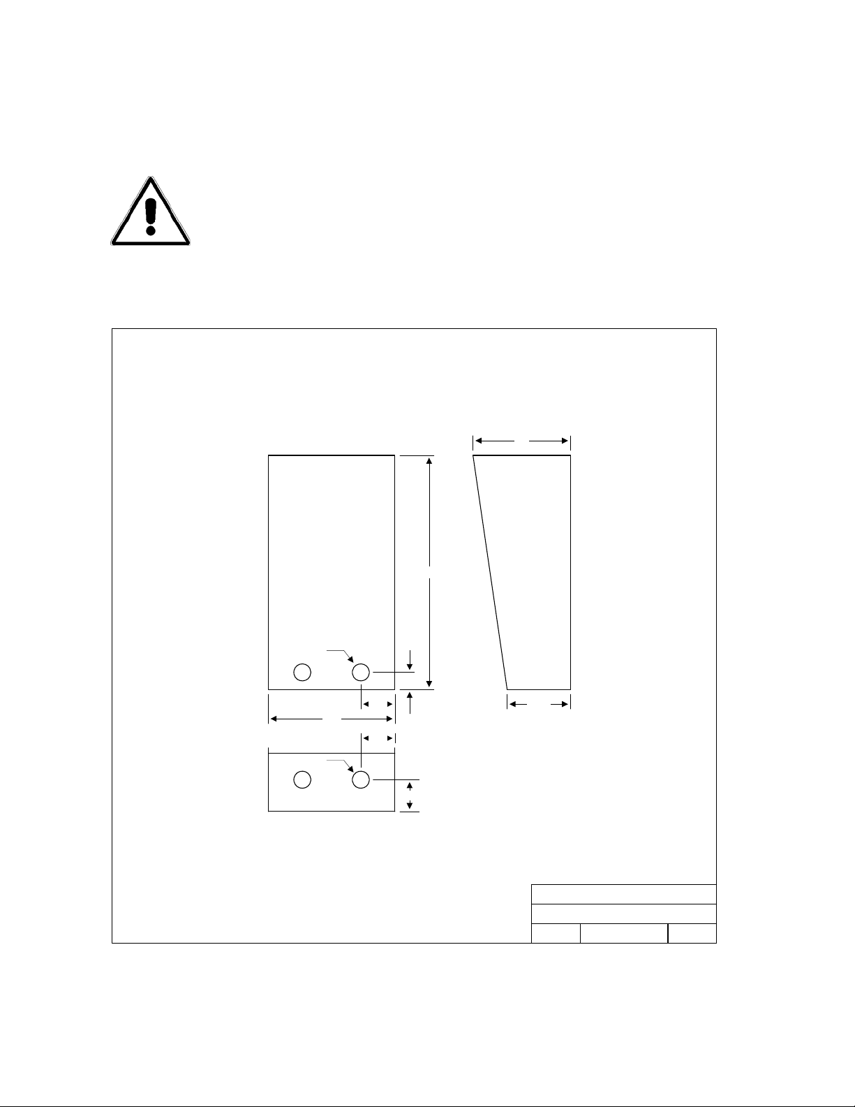
1.2 Surface Mount Only
Surface mount units can be mounted directly to a wall or pilaster, or can be post mounted using a
DoorKing mounting post (p/n 1200-045 and 1200-046). Be sure the unit is mounted securely and is
not subject to vibration from closing doors or gates.
WARNING! If this entry system is used to control a vehicular gate with an
automatic gate operator, the entry system must be mounted a minimum of
ten (10) feet away from the gate and gate operator, or in such a way that a
person cannot operate the entry system and touch the gate or gate operator
at the same time.
1819 Surface Mount Housing
5.0
.875 D
.875 D
6.50
1.75
1.75
.875
1.625
12
3.375
DOORKING, INC., INGLEWOOD, CA 90301
1819 Surface Mount Case
Title:
9/03
Date: Dwg. No. Rev.
M1800-065-9
A
Page 12

1819-065-B-4-07
1.3 Memory Chip Installation
The telephone entry system is shipped with a memory chip packaged in a separate box inside the
shipping container. The memory chip must be installed for the telephone entry system to opera te.
CAUTION!! Do not install the memory chip with power to the telephone entry system turned
on. Attempting to install the memory chip with power on will irrevocably damage the chip.
CAUTION!! The memory chip is a static sensitive component. Discharge any static electricity
from your hands by touching a proper ground device before removing the control board.
Handle the memory chip with care.
1. The large memory chip socket is colored blue and is located on the right hand side of the
circuit board. Be sure that the handle is in the un-locked position (towards the left). Be
sure that power to the telephone entry system is off.
2. Carefully insert the memory chip into the socket. The small half circular indentation on
the chip must be at the top. CAUTION: Installing the memory chip upside down will
cause permanent damage to the chip. Be sure that the memory chip is seated correctly
in the socket.
3. Move the lever on the chip socket to the locked position (towards the right).
Page 13

1819-065-B-4-07
Page 14

1819-065-B-4-07
SECTION 2 – WIRING & ADJUSTMENTS
Prior to installing wiring to the telephone entry system, we suggest that you become familiar with the
instructions, illustrations, and wiring guidelines in this manual. This will help insure that you
installation is performed in an efficient and professional manner.
The wiring of the telephone entry panel is an extremely important. Use proper wire for the
communication line, power wires, and be sure that the system is properly grounded. Check
all local building ordinances and building codes prior to installing this system. Be sure your
installation is in compliance with National Electric and local building codes.
WARNING! If this telephone entry system is used to control a vehicular gate
with an automatic gate operator, the telephone entry system must be
mounted a minimum of ten (10) feet away from the gate and gate operator or
in such a way that a person cannot operate the entry system and touch the
gate or gate operator at the same time. If this unit has not been installed in
compliance with these instructions, do not proceed with any wiring until the
unit has been moved and re-installed in accordance with these instructions.
Use only the supplied transformers (or U.L. listed equivalent) to power the telephone entry
system (16.5 VAC, 20 VA, 60 Cycle). Do not connect the power transformer to a receptacle
controlled by a switch.
Do not power any other devices (electric strikes, magnetic locks, etc.) from this power transformer.
For wire runs up to 100 feet, use 18 AWG, 600 volt insulated wire. For wire runs up to 200 feet, use
16 AWG, 600 volt insulated wire. Power wires are susceptible to noise and hum pickup; therefore it is
preferable that you keep power wire runs as short as possible.
This telephone entry system contains a number of static sensitive components that can be damaged
or destroyed by static discharges during installation or use. Discharge any static prior to removing
the circuit board from the lobby panel by touching a proper ground device.
Proper grounding of this system is a requirement. The use of surge suppressers can significantly
reduce the chance of component failure because of static charges or surges. To be effective, ground
connections should be made with a minimum 12 AWG, 600 volt insulated wire to a ground point
within 10 feet of the telephone entry system. The ground point must be at an electrical panel, a
metallic cold water pipe that runs in the earth, or a grounding rod driven at least ten (10) feet into the
soil.
Be sure that you use proper wire that has an insulation rated for an underground environment. All
wires should be placed in conduits. Proper pre-planning can greatly ease the installation and wiring
of this system. Always check with the local building code to determine the type of wire required in
your municipality.
Page 15

1819-065-B-4-07
2.1 Circuit Board Adjustments
1862-010 Control Board Adjustments
ON
Master
Code
OFF
CLICK
SENS
REV H Boards and later.
1
REV I Boards and later.
2
MIN MAX
MIC
1
VOLUME
MIN MAX
RING PIN
3 42 7 85 6 11 129 10 14131
KEYPAD CONNECTOR
FEEDBACK
SPEAKER
VOLUME
MIN MAX
TONE ON
MIN MAX
2
HANDS
HANDSET
FREE
DOORKING, INC., INGLEWOOD, CA 90301
Title:
1819 Control Board Adjustments
Date: Rev.Dwg. No.
4/07
M1819-065-2
A
TONE OFF
2
Page 16

1819-065-B-4-07
2.2 Wiring Diagram
1819 Field Wire Diagram - 1862-010 Control Board
1862-010
Circuit Board
MAIN TERMINAL
Phone Line Wiring Max Distance
800 Feet
1600 Feet
24 AWG
22 AWG
Phone
Line
5
Earth
Ground
6
4
16 Volt, 20 VA UL Listed power transformer.
1
Power for door strikes or magnetic lock is not provided by the
2
system. It must be provided by an external power supply.
Electric strikes are wired to Normally Open (N.O.) contacts; magnetic
3
locks are wired to the Normally Closed (N.C.) contac ts.
Optional 12 Volt gel cell for backup power.
4
Dedicated Central Office (C.O.) phone line - touch tone, loop st art .
5
A switch closure across terminals 4 & 8 will activate rela y 1 for its programmed
6
strike time. This is where the postal switch is prewired.
All wiring to be performed in accordance with National Electric Code.
10 11 12 13 14198765432
Power Wiring Max Distance
PWR
INPUT
100 Feet
200 Feet
18 AWG
16 AWG
1
Gate
Operator
Lock
Pwr
Strike /
Mag Lck
32
DOORKING, INC., INGLEWOOD, CA 90301
Title:
1819 Field Wire Diagram - 1862 Control Board
4/07
Date: Rev.Dwg. No.
M1819-065-1
A
Page 17

1819-065-B-4-07
2.3 Terminal Description
MAIN
TERMINAL
1 Phone Line Connection – 800 ft. maximum with 24 AWG wire; 1600 ft. maximum with 22 AWG wire.
2 Phone Line Connection – 800 ft. maximum with 24 AWG wire; 1600 ft. maximum with 22 AWG wire.
3 Earth Ground Only – Not a Low Voltage Common!
4 Switch Input 1. A closure between terminals 4 and 8 will cause relay 1 to activate for the programmed
strike time. The Postal Switch is connected here.
5 Microphone Input – White Wire.
6 Microphone Input – Green Wire.
7 Speaker Output.
8 Common for switch input 1, speaker and battery NEGATIVE (12 VDC).
9 Microphone Input – Red Wire and battery POSITIVE (12 VDC).
10 Relay 1 Common.
11 Relay 1 Normally Closed (N.C.).
12 Relay 1 Normally Open (N.O.).
13 16 VAC Input Power – 20 VA minimum.
100 ft. maximum with 18 AWG wire; 200 ft. maximum with 16 AWG wire.
14 16 VAC Input Power – 20 VA minimum.
100 ft. maximum with 18 AWG wire; 200 ft. maximum with 16 AWG wire.
DESCRIPTION
Do not run high voltage (115 V) power lines and communication lines in the same conduit. These
should be in separate conduits at least six (6) inches apart. Be sure that all phone line wiring is
twisted and completely isolated from ground.
Use only the supplied 16.5 VAC (or U.L. listed equivalent) to power the entry system. Do not power
any other devices (electric strikes, magnetic locks, lights, etc.) from this transformer. Do not
run 16 VAC entry system power lines over 200 feet. It is advisable to keep these wires as short as
possible. Use 18 AWG wire for wire runs up to 100 feet, and 16 AWG wire for wire runs up to
200 feet. Install a low voltage surge suppresser (DoorKing p/n 1878-010 or equivalent) to help
protect the entry system from power surges.
Page 18

1819-065-B-4-07
2.4 Adjustments
2.4.1 Speaker Volume
1. Open the front of the telephone entry system and locate the speaker volume adjustment.
2. Place a phone call from the telephone entry system. While the called person is talking,
adjust the speaker volume potentiometer for adequate sound. To increase the volume
rotate the potentiometer clockwise, to decrease the volume rotate the potentiometer
counter clockwise. See Feedback adjustment (2.4.3 step 5).
2.4.2 Microphone Volume
1. Open the front of the telephone entry system and locate the microphone volume
adjustment (Rev H boards and higher only).
2. Place a phone call from the telephone entry system. Talk to the called person in a
normal voice while adjusting the microphone volume potentiometer. Ask the person to let
you know when the sound in their telephone is adequate. To increase the volume rotate
the potentiometer clockwise, to decrease the volume rotate the potentiometer counter
clockwise. See Feedback adjustment (2.4.3 step 5).
2.4.3 Feedback
1. Place a phone call from the telephone entry system. When the call is picked up, ask the
person who answered to remain silent.
2. Open the front of the telephone entry system. Remove the jumper from the TONE OFF
terminals and place it on the TONE ON terminals. A tone will be heard in the speaker.
3. Rotate the feedback potentiometer clockwise, and then counter clockwise. When the
tone from the speaker is minimum, this is the correct adjustment.
4. Move the jumper back to the TONE OFF terminals when complete.
5. High microphone and speaker volume levels may cause feedback. It may be necessary
to reduce the speaker volume if the microphone volume is set too high. Likewise, it may
be necessary to reduce the microphone volume if the speaker volume is set too high.
2.4.4 Click Sensitivity (Optional - adjust only if a rotary dial phone is called)
1. Open the front of the telephone entry system and locate the click sensitivity adjustment.
2. Place a phone call from the telephone entry system to a person with a rotary dial type
phone. After they answer, ask the person to dial 9 while you adjust the click sensitivity
potentiometer (the person may have to dial 9 several times for you to obtain the correct
adjustment). When the door or gate opens, this is the correct adjustment for the click
sensitivity.
3. NOTE: Adjusting the click sensitivity too high (potentiometer fully clockwise) could cause
the system to respond to loud noises while it is in use. If this happens, rotate the click
sensitivity potentiometer counter clockwise 1/8 turn and re-test the system. You may
have to perform this step several times to find the correct adjustment.
Page 19

1819-065-B-4-07
2.4.5 Master Code Switch
The master code switch is left in the off position for normal operation. Turn the master code
switch on when setting the system master code. See programming instructions to set the
system master code.
If the master code switch is turned on and a new master code is not entered, the system will
sound a long tone after approximately 30 seconds. This tone will continue every 30 seconds
until a new master code is entered, or until the switch is turned off. After the switch is turned
off, the display will remain lit for approximately 30 seconds, and then will go off.
2.4.6 Ring Pin
The ring pin-shorting bar is labeled RING on the control board. This shorting pin must be
installed to allow the system to answer any calls placed to it. If remote programming or
remote relay operation is to be used, the shorting bar must be installed. Removing the
shorting bar will cause the system to never answer any call placed to it.
Page 20

1819-065-B-4-07
SECTION 3 – PROGRAMMING
The DoorKing 1819 Information Phone is programmed using the 1818-030 keypad assembly or
remotely from an off premise location using a touch tone telephone. When programming from an off
site location with a touch-tone telephone, the RING pin must be installed on the circuit board (see
2.4.6). We recommend that you do not attempt programming from an off site location until you
become familiar with these programming instructions.
Programming with the Keypad
1. Plug the 1818-030 keypad assembly into
the keypad connector on the circuit board
(pg 16). Be sure the ribbon cable on the
keypad is pointed DOWN when plugged
into the keypad connector.
2. Follow the programming instructions as
described in each section of this manual.
The system will prompt you with short
1818-030
Keypad Assembly
1 2 3
4 5 6
7 8 9
0
Keypad Connector
on Circuit Board
(beep) tones when programming steps
have been followed correctly and with a
long tone (beeeeeep) when the
programming step is ended.
3. Once the programming is complete,
unplug the keypad assembly and save it
for future programming requirements.
Programming from an Offsite Location
Follow these steps when programming the system from an offsite location. You must use a touchtone telephone and the RING pin must be installed to perform off site programming.
1. Call the telephone number that the entry system is installed on from a touch-tone
telephone. The entry system will answer with a one second tone.
2. Follow the programming instructions as described in each section of this manual. The
system will prompt you with short (beep) tones when programming steps have been
followed correctly.
3. When complete, hang up. (You cannot use 0 # to end remote programming sessions).
Programming Notes
For a typical installation of the Information Phone, you will need to program only the 7-digit
telephone number into the system. All other programming parameters are factory set. These
instructions provide information if any of the factory default settings need to be changed.
When each programming step is performed correctly, a short tone (beep) will be heard. When the
programming session is ended, a long tone (beeeeeep) will be heard.
The blank symbol _ in the programming steps indicates numbers that you will need to enter, one
number per blank.
Page 21

1819-065-B-4-07
3.1 General Programming
3.1.1 Master Code
This programming step sets the system MASTER CODE. The master code is the four-digit number
required to gain access to the system memory. You need to know the master code prior to
performing any of the programming functions on the following pages.
NOTE: The master code cannot be programmed from an off-site location. The master code
can only be programmed from the system keypad.
Factory setting = 9999
1. Open the cabinet of the telephone entry system and turn the master code switch (the
small toggle switch) on.
2. Enter a four-digit master code _ _ _ _ then press * (beep).
3. Turn the master code switch off and close the cabinet.
3.1.2 Single or Multiple Systems
This program sequence sets the telephone entry system to operate as a single unit on the phone line,
or to share the phone line with other units. If multiple systems are sharing the same phone line, then
each one must be set as a "multiple system" and each must have a unique master code.
Factory setting = 0 (Single System).
1. Press *04 and then enter the four-digit MASTER CODE _ _ _ _ (beep).
2. Enter 0* (beep) for a single system or 1* (beep) for multiple systems.
3. Press 0# TOGETHER to end this programming step (beeeeeep).
3.1.3 Relay Strike Time
These steps will program Relay 1 strike time. The strike time can be programmed from 1/4 second
(enter 00 in step 3) up to 99 seconds by entering the desired time in seconds.
Factory setting for relay strike time is 01.
1. Press *03 and enter the four-digit MASTER CODE _ _ _ _ (beep).
2. Press 1* to set relay 1 (beep).
3. Enter the two-digit strike time _ _ (00-99) then press * (beep).
4. Press 0# TOGETHER to end this programming step (beeeeeep).
Page 22

1819-065-B-4-07
3.1.4 Tone Open Numbers
These steps will program the tone open numbers for relay 1. You will need to enter a four-digit
number (see chart below) to set the relay functions. If a function is not desired, enter # in place of a
number. For example, if you want the relay to have a momentary activation function only, and you
want the relay to activate when the number 9 is pressed, enter 9 # # # in step 3. Do not duplicate
tone open numbers.
Factory setting is 9876.
1. Press *05 and enter the four-digit MASTER CODE _ _ _ _ (beep).
2. Press 1* to set tone numbers (beep).
3. Enter the four-digit tone open number code _ _ _ _ then press * (beep).
4. Press 0# TOGETHER to end this programming step (beeeeeep).
DIGIT FUNCTION
1 Momentary activation. Relay will activate for the programmed strike time (3.1.3).
2 Relay hold. Relay will activate and remain activated until commanded to release.
3 Relay release. Deactivates the relay hold command.
4 Relay hold 1-hour. Relay will activate for 1-hour and then will automatically deactivate itself.
3.1.5 Touch-tone / Rotary-dial
This programming sequence will set the telephone entry system to dial out in either a touch-tone or
rotary format. Generally, this will be set for touch-tone.
Factory setting = 0 (touch-tone).
1. Press *07 and enter the four digit MASTER CODE _ _ _ _ (beep).
2. Enter 0* (beep) for touch-tone or enter 1* (beep) for rotary.
3. Press 0# TOGETHER to end this programming step (beeeeeep).
3.1.6 Number of Rings to Answer
This programming sequence sets the number of rings to allow before the telephone entry system
answers a call placed to it. This programming sequence does not affect the number of times that a
resident’s telephone will ring when a call is placed from the entry system to the resident.
Factory setting = 02 (two rings).
1. Press *18 and enter the four-digit MASTER CODE _ _ _ _ (beep).
2. Enter the number of rings _ _ then press * (beep).
3. Press 0# TOGETHER to end this programming step (beeeeeep).
Page 23

1819-065-B-4-07
3.1.7 System to Stay On-Line or Hang Up after Touch Tone
This programming sequence provides a method for the telephone entry system to remain on line after
a resident has pressed the touch tone number to open the door or gate.
Factory setting = 1 (hang up after touch tone).
1. Press *28 and enter the four-digit MASTER CODE _ _ _ _ (beep).
2. Press 1* (beep).
3. Press 0* (beep) to keep the system on line, or press 1* (beep) to make it hang up.
4. Press 0# TOGETHER to end this programming step (beeeeeep).
3.1.8 Automatic Hang-up Function
This programming sequence determines when the phone system will automatically hang itself up
after a predetermined time of inactivity. You can program the system to not hang-up (0), to hang-up
after 5 sec of dial-tone (1), to hang-up after 15 sec of silence (2) or to hang-up afte r either 5 sec of
dial-tone or 15 sec of silence (3). NOTE: This programming function is available on REV G
boards or higher only.
Factory setting = 1 (hang-up after 5 sec of dial-tone).
1. Press *40 and enter the four-digit MASTER CODE _ _ _ _ (beep).
2. Enter the hang-up code desired _ then press * (beep).
3. Press 0# TOGETHER to end this programming step (beeeeeep).
Code Function
0 No hang-up.
1 Hang-up after 5 sec. of dial-tone (Factory setting).
2 Hang-up after 15 sec. of silence.
3 Hang-up after 5 sec. of dial-tone OR 15 sec. of silence.
3.1.9 Call Button to Dial Out
This programming sequence sets the CALL button to dial the phone number programmed in 3.2.1.
1. Press *23 and enter the four-digit MASTER CODE _ _ _ _ (beep).
2. Enter 2* (beep).
3. Enter 1* (beep).
4. Press 0# TOGETHER to end this programming step (beeeeeep).
Page 24

1819-065-B-4-07
3.2 Phone Number programming
3.2.1 Programming 7-digit Phone Numbers
In this programming sequence, the directory code and 7-digit phone number will be programmed into
the system. To program phone numbers that will be referenced to an area code (long distance calls
and 10 digit calling), follow the instructions under Long Distance Phone Number Programming.
NOTE: If this telephone entry system is being used in an area that requires 10-digit dialing,
proceed to 3.2.2 and 3.2.3 to program the area code and phone number.
1. Press *01 and enter the four-digit MASTER CODE _ _ _ _ (beep).
2. Enter 001 then press * (beep).
3. Enter the seven-digit phone number _ _ _ _ _ _ _ then press * (beep). If the number that
you are entering in this step is less than seven-digits, enter # in the empty spaces. For
example, if the system is connected to a PBX that requires four-digit extension numbers
and you want to enter extension 2217, you would enter this number as 2217### then
press * (beep).
4. Press 0# TOGETHER to end this programming step (beeeeeep).
3.2.2 Programming Area Code
Use this programming sequence for any 10-digit or long distance calling requirement. The area code
will be entered as a four-digit number (1 + the three digit area code). If the area code is being
programmed to facilitate 10-digit calling requirements, precede the three-digit area code with #.
1. Press *24 and enter the four-digit MASTER CODE _ _ _ _ (beep).
2. Enter a 2-digit area code reference number _ _ (01 through 15) then press * (beep).
3. Enter the area code _ _ _ _ then press * (beep). NOTE-1: for long distance calling
requirements, enter 1 and the three-digit area code. NOTE-2: for 10-digit calling
requirements, enter # and the three-digit area code.
4. Press 0# TOGETHER to end this programming step (beeeeeep).
3.2.3 Programming Phone Number with Area Code Reference
In this section, phone numbers that are referenced to an area code (long distance and 10-digit dialing
calls) will be programmed. Be sure that the area code(s) have been programmed as described in the
preceding section.
NOTE: If long distance or 10-digit dialing is not required, program the seven digit telephone
numbers as described in 3.2.1.
1. Press *41 and enter the four-digit MASTER CODE _ _ _ _ (beep).
2. Enter 001 then press * (beep).
3. Enter the 2 digit area code reference number _ _ then press * (beep).
4. Enter the seven-digit phone number _ _ _ _ _ _ _ then press * (beep). If the number
that you are entering in this step is less than seven-digits, enter # in the empty
spaces. For example, if the system is connected to a PBX that requires four-digit
extension numbers and you want to enter extension 2217, you would enter this
number as 2217### then press * (beep).
5. Press 0# TOGETHER to end this programming step (beeeeeep).
Page 25

1819-065-B-4-07
3.2.4 Deleting Individual Phone Numbers
This programming sequence is used to delete a single phone number.
1. Press *01 and enter the four-digit MASTER CODE _ _ _ _ (beep).
2. Enter 001 then press * (beep).
3. Press # # # # # # # then press * (beep).
4. Press 0# TOGETHER to end this programming step (beeeeeep).
Page 26

1819-065-B-4-07
3.3 Time Functions Programming
3.3.1 Time Clock Programming
This programming sequence programs the calendar chip in the telephone entry system for the current
time and date. The calendar chip must be programmed if you are going to use any of the time
functions available with the entry system.
1. Press *33 and enter the four-digit MASTER CODE _ _ _ _ (beep).
2. Enter the current hour and minutes _ _ _ _ then press * (beep). Do not use military
(24 hour) time format, simply enter the hour (2 digits) and the minutes (2 digits). For
example, 8:30 is entered as 0830 whether it is AM or PM.
3. Press 0* (beep) for AM, or press 1* (beep) for PM.
4. Enter the month _ _ then press * (beep).
5. Enter the day of the month _ _ then press * (beep).
6. Enter the year _ _ then press * (beep).
7. Enter the day of the week _ (Sun = 1, Sat = 7) then press * (beeeeeep).
3.3.2 Automatic Relay Activation Time Zones
This program sequence sets up time zones to automatically activate and deactivate the relays on the
control board. Each relay can be programmed with two independent time zones. Time zones 1 and 2
affect relay 1 operation; time zones 3 and 4 affect relay 2 operation. Use the chart in the appendix to
record the time zones that are programmed. These time zones can be independently turned on or
turned off after they have been programmed (see operating instructions 4.2.4).
1. Press *35 and enter the four-digit MASTER CODE _ _ _ _ (beep).
2. Enter a time zone number (1 or 2) then press * (beep).
3. Press 1* (beep) to turn the time zone ON, or press 0* (beep) to turn the time zone
OFF.
4. Enter the beginning hour and minutes _ _ _ _ then press * (beep).
5. Press 0* (beep) for AM, or press 1* (beep) for PM.
6. Enter the ending hour and minutes _ _ _ _ then press * (beep).
7. Press 0* (beep) for AM, or press 1* (beep) for PM.
8. Enter the days of the week _ _ _ _ _ _ _ then press * (beep). To skip any days of the
week, enter # in place of the day. For example, to have a time zone active on
Saturday and Sunday only (Sun = 1, Sat = 7), enter 1 7 # # # # #.
9. Repeat steps 2 through 8 to enter time zone 2.
10. Press 0# TOGETHER to end this programming step (beeeeeep).
Page 27

1819-065-B-4-07
Page 28

1819-065-B-4-07
SECTION 4 – OPERATING INSTRUCTIONS
Never allow children to operate or play with any access control device.
4.1 General Instructions
4.1.1 Calling Instructions
When the CALL button is pressed, the system will call the preprogrammed telephone number. If the
line is busy, the system will emit a busy signal. Pressing the CALL button will hang the system up.
4.1.2 Responding to a Call
When communication is established, the call recipient has the option of opening the door or gate by
pressing the programmed tone open number(s) on their touch tone telephone, or they can deny
access to their guest by pressing # on their telephone. If access is granted, the call recipient will hear
a confirmation tone in their handset indicating that the door or gate has opened, then the system will
automatically hang up.
Always press the # key on the telephone if you wish to deny a person access. If you hang up to
deny access instead of pressing #, the telephone entry system will remain on line until its
programmed talk time expires or until it detects dial tone.
Some newer type telephones emit a short tone rather than a continuous tone when their keys are
pressed. This may cause the telephone entry system to not respond to the tone open number. If this
happens, simply press the tone open number twice in rapid succession to open the door or gate.
Page 29

1819-065-B-4-07
4.2 System Administrator
The administrator can perform the following operations from a remote location using a touch-tone
telephone. You must know the phone number of the system and the system master code.
4.2.1 Remote Programming
1. Call the telephone number that the entry system is installed on. The system will answer
with a short tone (beep). Note: the number of rings before the system answers is
dependent on the programming in 3.1.6.
2. After the system answers, follow the desired programming steps in Section 3.
3. When complete, hang up. You cannot use 0# together to end the programming step from
a touch-tone telephone.
4.2.2 Remote Relay Activation
1. Call the telephone number that the entry system is installed on. The system will answer
with a short tone (beep). Note: the number of rings before the system answers is
dependent on the programming in 3.1.6.
2. Press *16 and enter the four-digit MASTER CODE _ _ _ _ (beep).
3. Press the desired tone open number _ (beep). NOTE: Refer to 3.1.4 to determine which
tone open features have been programmed, i.e. momentary open, hold open, release,
hold open one hour and then release.
4. Hang up.
4.2.3 Relay Check
The telephone entry system can be called and a check can be made to determine if the relay in the
system is in a "hold open" mode. This check can be useful if your gate (or door) is held open and you
suspect that the telephone entry system relay may be the cause.
1. Call the telephone number that the entry system is installed on. The system will answer
with a short tone (beep). Note: the number of rings before the system answers is
dependent on the programming in 3.1.6.
2. Press *16 and enter the four-digit MASTER CODE _ _ _ _ (beep).
3. The system will emit a series of short tones if the relay is in a continuous activation mode.
Relay 1 activated: beep - pause - beep - pause . . .
4. Press the programmed tone number _ to deactivate the relay (beep). The system will
automatically hang up.
Page 30

1819-065-B-4-07
4.2.4 Auto Relay Time Zone Enable / Disable
The two time zones that automatically activate and deactivate the relay can be turned off or on from a
touch-tone telephone at any time without changing the time zone boundaries. To program the auto
relay activation time zone boundaries, see section 3.3.2.
1. Call the telephone number that the entry system is installed on. The system will answer
with a short tone (beep). Note: the number of rings before the system answers is
dependent on the programming in 3.1.6.
2. Press *35 and enter the four-digit master code _ _ _ _ (beep).
3. Enter the time zone number _ that you want to turn off or on, then press * (beep).
4. Press 0* (beep) to turn the time zone OFF, or press 1* (beep) to turn the time zone ON.
5. Hang up or if at the system keypad, press 0# together (beeeeeep).
Page 31

1819-065-B-4-07
4.3 Miscellaneous Operating Instructions
4.3.1 Line Sharing
More than one telephone entry system can share the same phone line provided that the units have
been programmed for multiple systems on the same line (see 3.1.2). When the unit is programmed
for multiple systems sharing the same line, it checks the phone line for 48 volts (not busy) before
attempting to place a call. If the phone line is in use, the system will emit a busy signal. If two or
more systems are sharing the same phone line, it is important that each system be programmed with
its own unique master code. When more than one system is on the same phone line, and a call is
placed from one of the systems to a resident, only the system that placed the call will respond to any
tone open numbers. Do not be concerned that all the units will activate their relay when the resident
presses the tone open number.
4.3.4 Connection to a PBX
If the telephone entry system is going to be connected to a PBX system, you may need to program
extension numbers in place of a seven-digit telephone number. To do this, enter the extension
number and fill the remaining spaces with the # key in the phone number programming step. For
example, if the PBX system uses four-digit extensions and you want to program extension 2217 as a
phone number, in step 3, section 3.2.1 press:
3. 2 2 1 7 # # # * (beep).
If the PBX system requires you to dial 9 to obtain an outside line, and you want to program some
outside line phone numbers in the system, program the number 9 as one of the alternate area codes.
In step 3, section 3.2.2 press:
3. 9 # # # *(beep).
Then program the outside phone number as a long distance number (3.2.3) using the area code
reference number used to program 9.
4.3.5 Areas with 10-digit Dialing
If the telephone entry system is installed in an area where the telephone company has instituted 10
digit dialing, simply program the required number of alternate area codes into the system without
preceding the area code with the number 1. If 310 was one of the area codes required, in step 3,
section 3.2.2 press:
3. 3 1 0 # * (beep).
Then program the outside phone number as a long distance number (3.2.3) using the area code
reference number used to program 310.
Page 32

1819-065-B-4-07
SECTION 5 – MAINTENANCE
The DoorKing telephone entry system is essentially a maintenance free device. When the unit is
properly installed, it should provide years of trouble free service. Maintenance is limited to updating
the directory and phone number and/or entry codes when residents move in or out.
The faceplate of the unit should be cleaned on a regular basis to keep contaminants in the air from
sticking to the surface and possibly causing pitting. When cleaning the faceplate of the system, never
use an abrasive cleaner or cloth. Stainless steel cleaner works very well with a soft cloth for systems
with a stainless steel faceplate. A clean damp soft cloth should be used to clean gold plated
faceplates.
5.1 Replacement Parts
The following items are replaceable and can be ordered from your installing dealer.
Keypad Programming Keypad P/N 1818-030.
Circuit Board Replacement Circuit Board P/N 1862-010 REV I or higher.
Transformer Replacement power transformer – 16.5 VAC, 20 VA U.L. Listed
DoorKing P/N 1804-060
5.2 Trouble Shooting
If problems should develop with your telephone entry system, refer to the trouble-shooting guide on
the following pages to try and correct any problems. Our experience has shown that a majority of
reported problems are actually programming related and can be corrected on site. If problems persist
and they cannot be corrected, contact your authorized DoorKing dealer for assistance. Before
performing any trouble-shooting, check the following:
1. Have a good VOM meter handy to check voltages and continuity.
2. Have a telephone test set (DoorKing p/n 1800-050 or equivalent) to check the
telephone line. Noise on the phone line will cause problems with the entry sy stem.
3. Be sure that the entry system case is properly grounded.
4. Be sure that the telephone wires are twisted.
5. A hum on the system indicates that the phone line or 16 VAC power lines may be
grounded. Check to be sure that the phone lines or power lines are not shorted to
ground.
6. Check the 16 VAC system power. Be sure that the transformer is properly rated (16
VAC, 20 VA). Keep the wire run from the transfor mer to the en try system as short as
possible. Use 16 or 18 AWG, 600 volt insulated wire only. The importance of
proper power wiring cannot be over stressed!
7. Isolate the telephone entry system. Disconnect any external devices, such as gate
operators, electric strikes, magnetic locks, etc., which may affect the operation of the
system.
Page 33

1819-065-B-4-07
SYMPTON POSSIBLE SOLUTION(S)
Cannot get into
programming mode.
System emits a long
tone and cancels
programming.
Preprogrammed
phone number does
not dial when CALL
button is pushed.
Buzz or noise on the
phone line.
Ringing or howling
from the speaker.
After dial out, dial tone
is heard on the
speaker.
Door strike locks on.
Door strike or gate
operator holds open.
Entry system will not
answer when called.
Rotary dial 9 will not
activate relay.
Touch-tone 9 will not
activate relay.
Relay activates but
gate operator will not
open.
System emits a beep
every 30 seconds.
• Wrong master code entered. Start over.
• Waiting too long between pushing buttons. Enter information quicker.
• Keypad is not plugged into board correctly. Cable points down.
• Memory chips are installed upside down.
• Waiting too long between pushing buttons.
• Forgetting to press * first when programming.
• Reprogram CALL button to dial out (3.1.9).
• Disconnect the phone line from the system and check it with a handset. If line
is noisy, problem is with the phone line and not the entry system.
• Check for any shorts to ground behind the circuit board.
• Check for pinched wires near the door hinge.
• Check for 16-volt power shorted to ground.
• Check for phone line shorted to ground.
• Check that phone wires are twisted.
• Check that the proper type of phone wire was used for an outdoor and / or
underground application.
• Check that all wires, speaker, keypad, etc. are isolated from ground.
• Check that the cabinet is properly grounded. Be sure that case ground
(terminal 3) is not used as a low voltage common.
• Check for excessive voltage drop on 16 VAC power.
• Feedback improperly adjusted (2.4.3).
• Volume is set too high (2.4.1).
• Phone line is a rotary-dial line. Have the phone company change it to a touch-
tone line.
• Excessive voltage-drop on 16 VAC line.
• Using a transformer with too low VA rating.
• Relay strike time programmed too long (3.1.3).
• Auto relay time zone enabled. Turn auto relay feature off or reprogram the
time zone (4.2.4).
• System was given a hold open command. Call the system and press the tone
deactivate number (4.2.2).
• Ring pin is not installed (2.4.6).
• Number of rings to answer is set to high. Reprogram (3.1.6).
• Bad phone line or insufficient ring voltage.
• Adjust click sensitivity (2.4.4).
• Re-program tone-open number to 9 (3.1.4).
• If resident phone emits a short pulse rather than a long tone, press 9 twice in
rapid succession 99.
• Try another phone that is known to work.
• Lower speaker volume (2.4.1) and re-adjust feedback (2.4.3).
• Re-program relay strike time for a longer period (3.1.3).
• Check wiring to gate operator.
• Check gate operator.
• Master code switch is in the ON position.
Page 34

1819-065-B-4-07
5.3 Accessories
Surge Suppressers High voltage (120 V) suppresser: P/N 1878-076.
Phone line suppresser: P/N 1878-077.
Low voltage (28 V) suppresser: P/N 1878-078.
Mounting Post Standard gooseneck mounting post: P/N 1200-045.
Standard gooseneck mounting post – long: P/N 1200-046
Telephone Test Set Includes clips, cord and carrying case. P/N 1800-050.
Battery 12 volt .8 amp hour gel cell provides stand by power during power
interruptions. P/N 1801-008.
Page 35

1819-065-B-4-07
5.4 Log Tables
Complete the information in the tables on the following pages to maintain a record of the information
that has been programmed into the telephone entry system if the system. Make copies of the
resident log sheet so that you have enough to complete a listing of all residents and data.
MASTER CODE
TONE OPEN NUMBERS RELAY 1
Momentary
Continuous
Release
Hold 1 Hour
RELAY STRIKE TIME
RELAY 1
AREA CODES
1 2 3 4 5 6 7 8 9 10 11 12 13 14 15
RELAY AUTO ACTIVATE TIME ZONES
ZONE 1 ZONE 2
Begin Time
End Time
Days of Week
Page 36

1819-065-B-4-07
Page 37
 Loading...