

DoorKing 1817 User Manual

Owner’s Manual
1803PC, 1815, 1817
PC Programmable Telephone Entry Systems
DoorKing, Inc.
120 Glasgow Avenue
Inglewood, California 90301
U.S.A.
Phone: 310-645-0023
Fax: 310-641-1586
www.doorking.com
P/N 1815-065 REV J, 3/01
Copyright 2001 DoorKing, Inc. All rights reserved.

2

Use this manual with the following models only.
t
All 1803PC models with circuit board 1844-010 REV A and B.
All 1815 models with circuit board 1840-010 REV D and E.
All 1817 models with circuit board 1841-010 REV F and G.
DoorKing, Inc. reserves the right to make changes in the products described in this manual
without notice and without obligation of DoorKing, Inc. to notify any persons of any such revisions
or changes. Additionally, DoorKing, Inc. makes no representations or warranties with respect to
this manual. This manual is copyrighted, all rights reserved. No portion of this manual may be
copied, reproduced, translated, or reduced to any electronic medium without prior written consen
from DoorKing, Inc.
3

TABLE OF CONTENTS
Preface
Important Notices......................................................................................................................................................6
General Information ..................................................................................................................................................7
Features ..................................................................................................................................................................8
Section 1 – Installation
1.1 Installation Guidelines – All Systems ...................................................................................................9
1.1.1 Surface Mount Units.................................................................................................................10
1.1.2 Surface Mount Units with Recess Box .....................................................................................11
1.1.3 Flush Mount Units ....................................................................................................................12
1.1.4 Flush Mount Rough-in Box.......................................................................................................13
1.1.5 Flush Mount Trim Ring .............................................................................................................14
1.1.6 Flush Mount Surface Mounting Kit ...........................................................................................15
1.1.7 Wall Mount Units ......................................................................................................................16
1.2 Memory Chip Installation.......................................................................................................................17
1.3 Postal Lock Installation..........................................................................................................................18
Section 2 – Wiring
General Information................................................................................................................................................19
Maximum Wire Run Distance Charts ....................................................................................................................20
2.1 Main Terminal Description.....................................................................................................................21
2.2 Weigand Terminals
2.2.1 Weigand Power Terminals .......................................................................................................22
2.2.2 Weigand Data Terminals..........................................................................................................22
2.2.3 Elevator Control Terminals.......................................................................................................23
2.2.4 RS-232 Terminals ....................................................................................................................23
2.3 Relay Wiring (Typical)
2.3.1 Controlling a Single Door or Gate ............................................................................................24
2.3.2 Controlling a Gate and a Pedestrian Gate or Door ..................................................................25
2.3.3 Controlling a Gate Operator and Two Pedestrian Doors or Gates...........................................26
2.3.4 Tracker Expansion Board Control ............................................................................................27
Section 3 – Programming
3.1 General Programming Information
3.1.1 Programming with a PC ...........................................................................................................29
3.1.2 Programming from the Keypad ................................................................................................30
3.1.3 System Memory........................................................................................................................31
3.2 Programming with a PC
3.2.1 Master Code.............................................................................................................................32
3.2.2 Single or Multiple Systems .......................................................................................................32
3.2.3 Programming for Call Up Operation .........................................................................................33
3.2.4 PC Programming Table............................................................................................................33
3.3 General Programming
3.3.1 Relay Strike Time .....................................................................................................................34
3.3.2 Talk Time..................................................................................................................................34
3.3.3 Tone Open Numbers................................................................................................................35
3.3.4 Postal Switch............................................................................................................................35
3.3.5 Touch-tone / Rotary-dial...........................................................................................................36
3.3.6 Rotary-dial 9 .............................................................................................................................36
4

3.4 Programming Letters, Numbers and Messages
3.4.1 Programming Letters and Numbers .........................................................................................37
3.4.2 Programming the User Message – 1815..................................................................................38
3.4.3 Programming the Instruction Message – 1815 ........................................................................39
3.4.4 Programming the User Message – 1817..................................................................................40
3.4.5 Programming the Instruction Message – 1817 ........................................................................41
3.5 Programming Phone Numbers and Names .........................................................................................42
3.5.1 Programming the Directory Code Length.................................................................................43
3.5.2 Programming 7-digit Phone Numbers......................................................................................43
3.5.3 Programming Area Codes........................................................................................................44
3.5.4 Programming Phone Numbers with Area Codes .....................................................................44
3.5.5 Programming Names ...............................................................................................................45
3.5.6 Deleting Individual Phone Numbers.........................................................................................45
3.5.7 Delete Names...........................................................................................................................45
3.5.8 Delete Area Codes...................................................................................................................46
3.5.9 Display Phone Numbers...........................................................................................................46
3.6 Device Codes
3.6.1 Programming Device Codes ....................................................................................................47
3.6.2 Deleting Device Codes.............................................................................................................47
3.7 Four-digit Entry Codes
3.7.1 Programming Four-digit Entry Codes.......................................................................................48
3.7.2 Delete Four-digit Entry Codes ..................................................................................................48
3.7.3 Entry Code Ranges ..................................................................................................................48
Section 4 – Adjustments
Circuit Board Adjustments ........................................................................................................................................49
1815 Adjustment Locations ......................................................................................................................................51
1817 Adjustment Locations ......................................................................................................................................52
Section 5 – Operating Instructions
5.1 Guest Instructions..................................................................................................................................53
5.2 Resident Instructions
5.2.1 Responding to a Guest Call .....................................................................................................54
5.2.2 Using an Entry Code ................................................................................................................54
5.3 System Administrator
5.3.1 Opening from a Remote Location ............................................................................................55
5.3.2 Tracker Board Override Hold Open Command ........................................................................55
5.3.3 Relay Check.............................................................................................................................56
5.3.4 Time and Date Check...............................................................................................................56
5.4 Miscellaneous Operating Instructions
5.4.1 Talk Time..................................................................................................................................57
5.4.2 Line Sharing .............................................................................................................................57
5.4.3 Connection to a PBX................................................................................................................57
5.4.4 10-digit Dialing .........................................................................................................................57
Section 6 – Maintenance and Trouble Shooting
6.1 Trouble Shooting
6.1.1 RS-232 Test .............................................................................................................................61
6.1.2 Weigand Test ...........................................................................................................................62
6.1.3 Elevator Board Hardware Test .................................................................................................62
6.1.4 Elevator Board Floor Hardware Test........................................................................................63
6.2 Accessories ..............................................................................................................................................64
6.2 Log Tables................................................................................................................................................65
5

IMPORTANT NOTICE
FCC - UNITED STATES
This equipment has been tested and found to comply with the limits for a class A digital device,
pursuant to Part 15 of the FCC Rules and Regulations. These limits are designed to provide
reasonable protection against harmful interference when the equipment is operated in a commercial
environment. This equipment generates, uses, and can radiate radio frequency energy and, if not
installed and used in accordance with the instruction manual, may cause harmful interference to radio
communications. Operation of this equipment in a residential area is likely to cause harmful
interference in which case the user will be required to correct the interference at his own expense.
FCC Registration Number: DUF6VT-12874-OT-T
DOC - CANADA
The Canadian Department of Communications label identifies certified equipment. This certification
means that the equipment meets certain telecommunications network protective, operational, and
safety requirements. The Department does not guarantee the equipment will operate to the users
satisfaction.
Before installing this equipment, users should ensure that it is permissible to be connected to the
facilities of the local telecommunications company. The equipment must also be installed using an
acceptable means of connection. The customer should be aware that compliance with the above
conditions may not prevent degradation of service in some situations.
Repairs to certified equipment should be made by an authorized Canadian maintenance facility
designated by the supplier. Any repairs or alterations made by the user to this equipment, or
equipment malfunctions, may give the telecommunications company cause to request the user to
disconnect the equipment.
Users should ensure, for their own protection, that the electrical ground connections of the power
utility, telephone lines, and internal metallic water pipe system, if present, are connected together.
This precaution may be particularly important in rural areas.
CAUTION: Users should not attempt to make such connections themselves, but should contact the
appropriate electric inspection authority, or electrician, as appropriate.
DOC Registration Number: 1736 4528 A
Notice:
The Load Number (LN) assigned to each terminal device denotes the percentage of the total load to
be connected to a telephone loop which is used by the device, to prevent overloading. The
termination on a loop may consist of any combination of devices subject only to the requirement that
the sum of the load numbers of all the devices does not exceed 100.
Notice:
DoorKing does not provide a power transformer on units sold into Canada. Use only transformers that
are CSA listed to power the telephone entry system. 1802, 1803, 1808, 1810, 1814, 1815, 1818 and
all "P" series systems require a 16.5-volt, 20 VA transformer. The models 1816 and 1817 require a
16.5-volt, 40 VA transformer. The model 1812 requires a 24-volt, 20 VA transformer.
Listing:
This product has been tested to and found to be in compliance with the U.L 294 Safety Standard by
Intertek Testing Services NA Inc. (a Nationally Recognized Testing Laboratory) and is ETL listed.
6

GENERAL INFORMATION
• Prior to beginning the installation of the telephone entry system, we suggest that you become
familiar with the instructions, illustrations, and wiring guidelines in this manual. This will help
insure that you installation is performed in an efficient and professional manner.
• The proper installation of the telephone entry panel is an extremely important and integral
part of the overall access control system. Check all local building ordinances and building
codes prior to installing this system. Be sure your installation is in compliance with local
codes.
• When used to control a door or pedestrian gate, try to locate the telephone entry system as
near as possible to the entry point. The unit should be mounted on a rigid wall to prevent
excessive shock and vibration from closing doors or gates. Continuous vibration and shock
from slamming doors or spring-loaded pedestrian gates will damage the circuit board. Under
no circumstances should the unit be mounted directly to a moving door or gate.
• ADA mounting requirements for door control. The mounting of the unit shall be in such a
way that the LCD display is positioned so that it is readily visible to and usable by a person
sitting in a wheelchair with an approximate eye level of 45 inches and shall comply with the
following requirements:
1. If mounted vertically or tipped no more than 30 degrees away from the viewer, the
center line of the LCD
2. If the clear floor space allows only forward approach to the system, the maximum
high forward reach allowed is 48 inches above grade to the top of the keypad.
3. If the high forward reach to the system is over an obstruction of greater than 20
inches but less than 25 inches, the maximum high forward reach allowed is 44 inches
above grade to the top of the keypad.
4. If the clear floor space allows parallel approach by a person in a wheelchair, the
maximum high side reach shall be 54 inches above grade to the top of the keypad.
5. If the high side reach is over an obstruction of 24 inches or less, the maximum high
side reach allowed is 46 inches above grade to the top of the keypad.
• When used to control a vehicular gate with an automatic gate operator, the telephone
entry system must be mounted a minimum of ten (10) feet away from the gate and gate
operator, or in such a way that a person cannot operate the entry system and/or touch
the gate or gate operator at the same time.
shall be located a maximum of 52 inches above grade.
• Be sure that the system is installed so that it is not directly in the traffic lane. Goose neck
mounting post and kiosks work well for these type systems. When planning where to locate
the system, take into consideration traffic lane layouts, turn around lanes for rejected access,
conduit runs, power availability, etc.
• Environmental factors must also be taken into account. Surface mount units are designed for
direct outdoor installations, however it is preferable to protect them from direct exposure to
driven rain or snow whenever possible. Flush mount and wall mount units must be protected
from direct exposure to the elements. Be sure that ample lighting is provided so that guest
can read both the directory and the operating instructions at night.
• This telephone entry system contains a number of static sensitive components that can be
damaged or destroyed by static discharges during installation or use. Discharge any static
prior to removing the circuit board from the lobby panel by touching a proper ground device.
7

FEATURES
• Can provide service for up to 3000 residents and can store up to 8000 card, transmitter or
digital PIN codes when ordered with 3000 MemPLUS chip set.
• System can be programmed via modem or RS-232 interface with the Remote Account
Manager for Windows software included with the unit. Programming via RS-232 requires an
additional cable that is not included with the unit (P/N 1818-040).
• System keypad will emit DTMF tones after a call is answered allowing the system to be used
with auto-attendants, answering machines, etc. This feature is available with the
following units only:
Model 1815 with 1840-010 circuit board, REV E or higher.
Model 1817 with 1841-010 circuit board, REV G or higher.
Model 1803PC with 1844-010 circuit board, REV B or higher.
• Directory codes can be set from 1 to 4 digits in length and can be randomly assigned.
• Transaction buffer stores the last 8000 events and has its own backup power source to retain
memory during power outages.
• 31-security levels total (security level 00 always denies entry, security level 01 always admits
entry), with 29 programmable security levels, each with four time zones allows you to control
and restrict user access as needed.
• 10 programmable area codes allow the system to be used in areas requiring 10 and 11-digit
dialing.
• Three internal relays allow the system to control a main entry point plus two additional entry
points.
• System can be expanded to control up to 16 entry points in addition to the main entry point.
Tracker expansion boards are required (one for each additional entry point) and are not
included with the system. Tracker boards also provide output for door ajar and forced entry
alarms.
• Optional elevator control board(s) can control up to four elevators with each elevator serving
up to 64 floors.
• System will interface with selected models of DKS DoorKing vehicular gate operators to
provide gate operator information and data (requires a Tracker board for each gate operator
that is to send data to the system).
8

SECTION 1 - INSTALLATION
Order your telephone line at least two weeks prior to the planned installation date. This will assure
that a phone line is available when the unit is installed. The telephone company will require the
following information from you:
Type: Touch Tone, Loop Start
Ringer Equivalence: 0.0 A
Jack Type: RJ11C
FCC Registration (US): DUF6VT-12874-OT-T
DOC (Canada): 1736 4528 A
Electrical Listing: Complies with U.L. 294 - ETL Listed
CALLER ID: You may want to consider ordering caller ID blocking from the telephone company for
the entry system phone line. Without caller ID blocking, tenants with the proper phone equipment will
be able to identify the telephone number that the entry system is installed on. This may or may not
be desirable.
1.1 INSTALLATION GUIDELINES – ALL SYSTEMS
1. Open the cabinet of the telephone entry system and disconnect the keypad ribbon cable
from the main circuit board.
2. Remove the 6-32 x 1/2 round head screws from the upper corners of the circuit board.
3. Remove the circuit board by gently pulling it out of the main terminal edge connector.
CAUTION - the circuit board contains static sensitive components. Discharge any static
electricity from your hands by touching a proper ground device before removing the
circuit board. Place the circuit board where it will not be damaged.
4. Mount the cabinet of the telephone entry system. Be sure that mounting screws do not
protrude into the cabinet where they could cause a short on the back of the circuit board.
Make any necessary conduit connections.
5. Route wiring into the cabinet. Do not apply any power at this time.
6. Clean out the cabinet. Be sure that all dirt, metal and/or wood debris is removed from the
cabinet and that the terminal strip edge connector is clean and free of any loose particles.
7. Re-install the circuit board into the cabinet by gently pushing the circuit board terminals
into the edge connector. CAUTION - the circuit board contains static sensitive
components. Discharge any static electricity from your hands by touching a proper
ground device before removing the circuit board.
8. Secure the circuit board to the cabinet using the screws removed in step 2.
9. Plug the keypad ribbon cable into the circuit board. The cable points down.
9
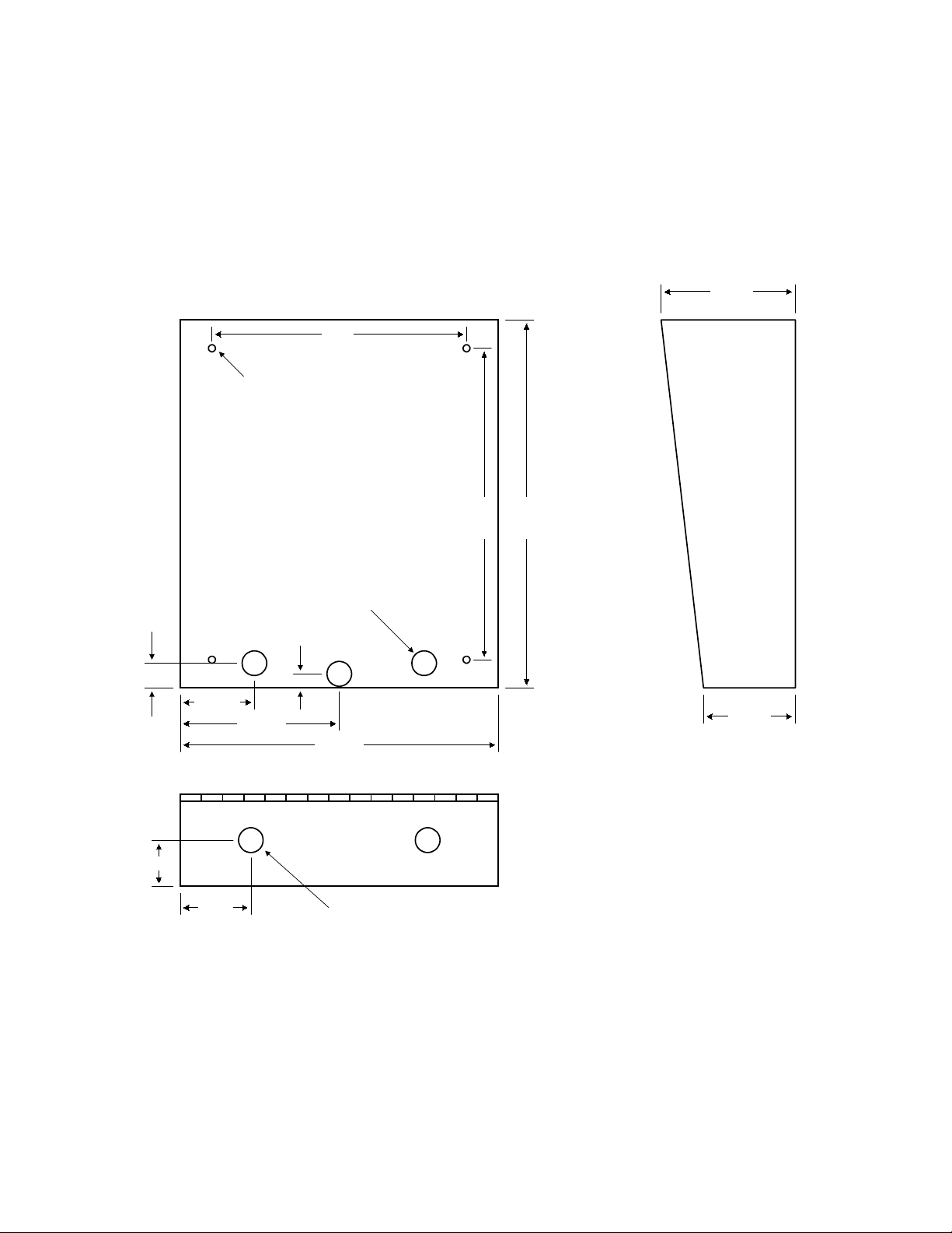
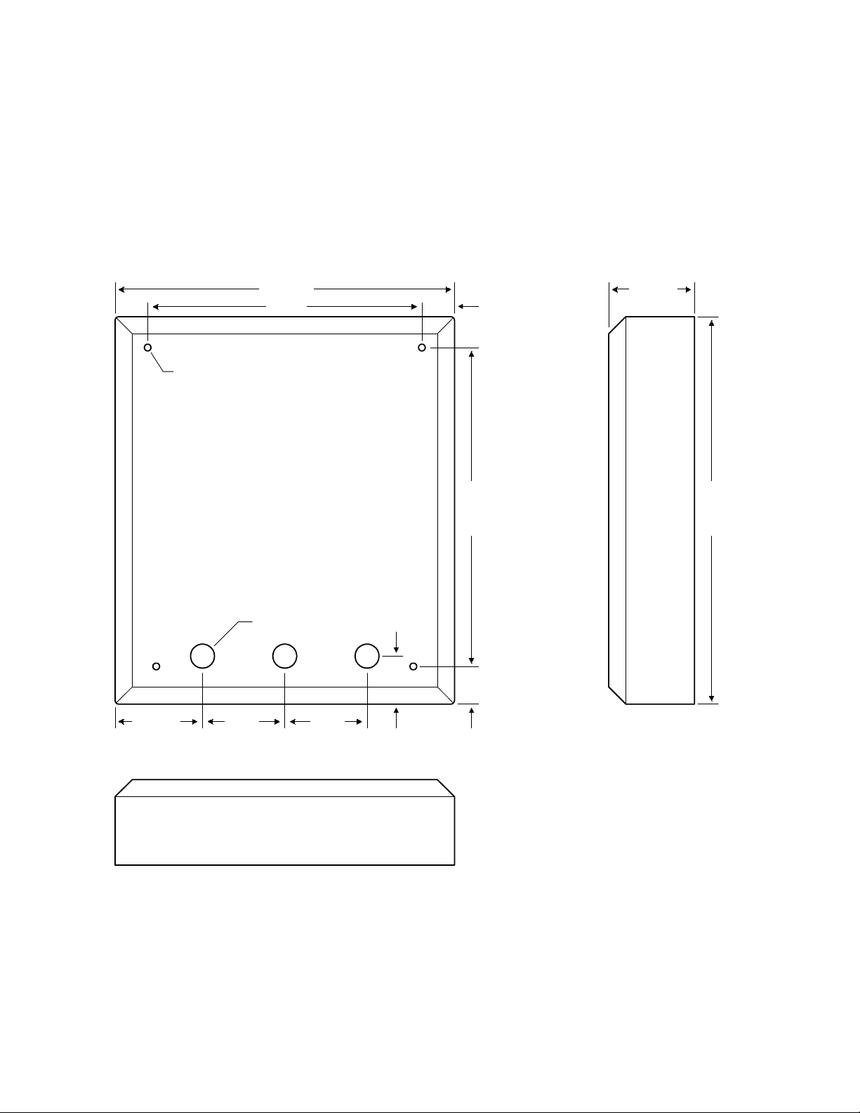
1.1.1 Surface Mount Units
Surface mount units can be mounted directly to a wall or pilaster, or can be post mounted using a
DoorKing heavy-duty mounting post (p/n 1200-047 and 1200-048). Be sure the unit is mounted
securely and is not subject to vibration from closing doors or gates.
CAUTON! If this entry system is used to control a vehicular gate with an automatic gate operator, the
entry system must be mounted a minimum of ten (10) feet away from the gate and gate operator, or
in such a way that a person cannot operate the entry system and touch the gate or gate operator at
the same time.
4.75
9.0
.25 DIA
13.0
11.0
1.625
.875
2.625
2.5
5.625
.875 DIA
.5
3.25
11.25
.875 DIA
10
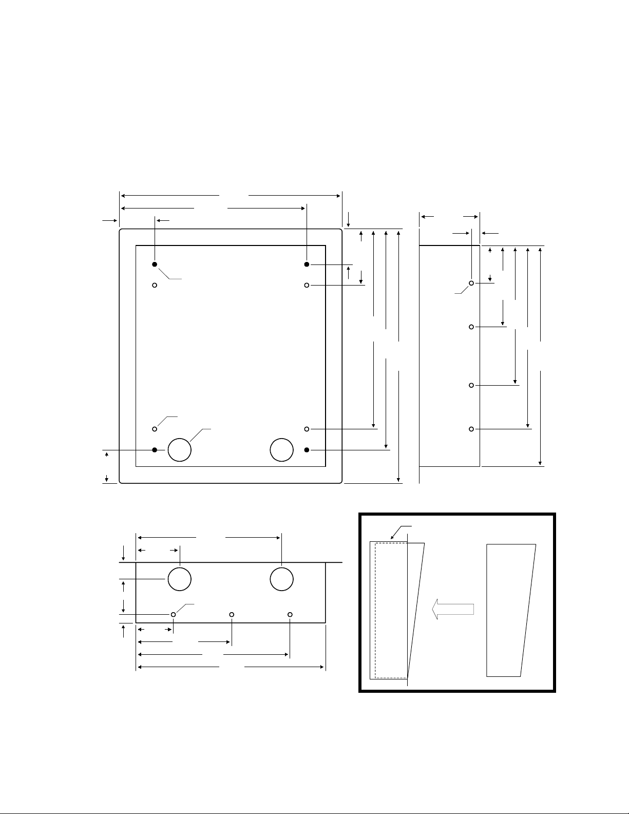
1.1.2 Surface Mount Units with Recess Box
Surface mount units can be semi-flush mounted into a wall or pilaster by using the optional recessmounting box (p/n 1803-150). Be sure the unit is mounted securely and is not subject to vibration
from closing doors or gates.
CAUTON! If this entry system is used to control a vehicular gate with an automatic gate operator, the
entry system must be mounted a minimum of ten (10) feet away from the gate and gate operator, or
in such a way that a person cannot operate the entry system and touch the gate or gate operator at
the same time.
15.00
11.125
2.125
2.125
3.625
.5
2.0
3.375
10-24 x 1.25 STUD
.25 DIA
12.0
13.25
15.25
.25 DIA
1.375 DIA
1803-150
1.06.5
2.68
8.812
Recess Box
2.25
4.875
Surface Mount
Entry System
8.375
11.0
13.25
2.2
5.75
.25 DIA
9.3
11.5
11

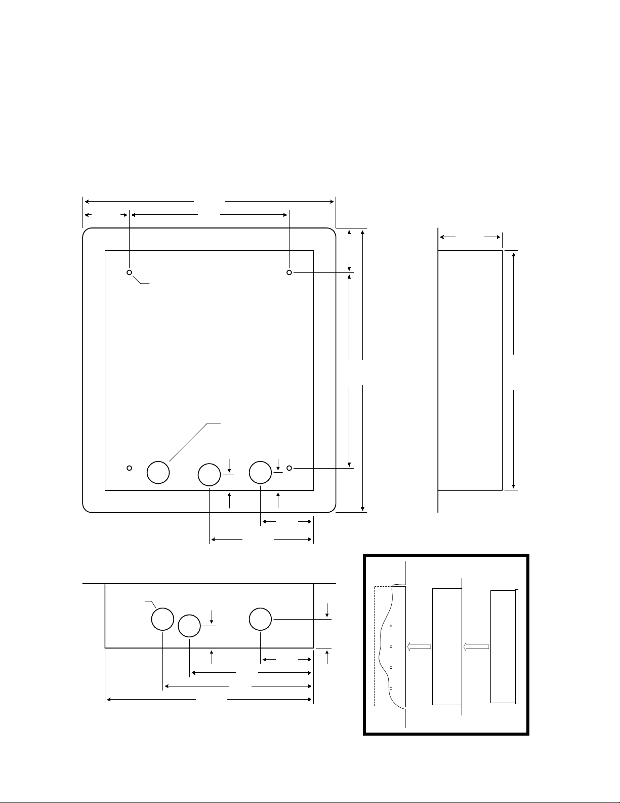
1.1.3 Flush Mount Units
Flush mount units are installed into a wall with flush mount kits 1814-065 (stainless) or 1814-066
(gold). Flush mount kits are not included with the entry system. Flush mount units are not designed
for direct exposure to the weather. Be sure the unit is mounted securely and is not subject to
vibration from closing doors or gates.
CAUTON! If this entry system is used to control a vehicular gate with an automatic gate operator, the
entry system must be mounted a minimum of ten (10) feet away from the gate and gate operator, or
in such a way that a person cannot operate the entry system and touch the gate or gate operator at
the same time.
.875
1.125
.25 DIA
.875 DIA
12.0
9.0
.50
11.0 1.125
13.25
3.0
13.0
2.625 2.625
5.625
11.25
.875 DIA
1.625
2.5
12

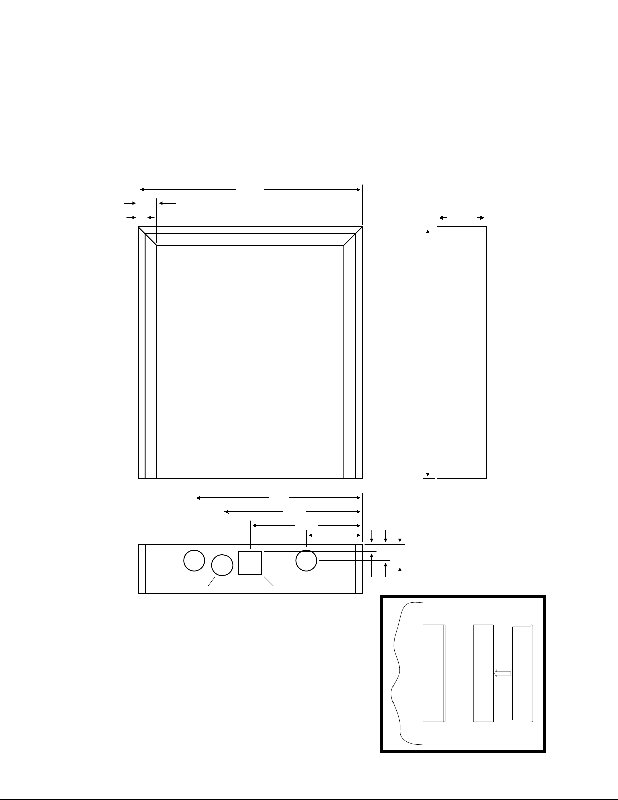
1.1.4 Flush Mount Rough-in Box
The flush mount installation kit has two parts; the rough-in box and the trim ring. The rough-in box is
installed first.
1.875
12.75
9.0
10-24 x 1.125 Stud
1.125 DIA
9.25
3.5
11.0 1.75
3.875
1.25
4.25
7.25
10.25
13.25
14.5
1.75
1.75
.25 DIA
11.0
6.375
1.75
13
1.1.5 Flush Mount Trim Ring
Flush mount units can be mounted by using the 1814-065 (stainless) or 1814-066 (gold) mounting kit.
Flush mounting kits are not included with the unit. Flush mount units are not designed for direct
exposure to the weather. Be sure the unit is mounted securely and is not subject to vibration from
closing doors or gates.
CAUTON! If this entry system is used to control a vehicular gate with an automatic gate operator, the
entry system must be mounted a minimum of ten (10) feet away from the gate and gate operator, or
in such a way that a person cannot operate the entry system and touch the gate or gate operator at
the same time.
14.25
2.625 9.0
3.625
.25 DIA
1.25 DIA
11.75
1.25 DIA
1.125
.875
8.5
7.0
5.875
1.0
3.0
3.0
1.625
11.0 2.25
16.0
Rough-in
Box
13.625
Trim
Ring
Flush Mount
Entry System
14
1.1.6 Flush Mount Surface Mounting Kit
Flush mount units can be surface mounted by using the optional 1814-152 surface mount trim ring.
Flush mount units are not designed for direct exposure to the weather. Be sure that the unit is
securely mounted and is not subject to vibration from closing doors or gates.
CAUTON! If this entry system is used to control a vehicular gate with an automatic gate operator, the
entry system must be mounted a minimum of ten (10) feet away from the gate and gate operator, or
in such a way that a person cannot operate the entry system and touch the gate or gate operator at
the same time.
12.0
1.0
.375
2.625
9.0
7.5
6.0
1.125 DIA 1.125 SQ
3.0
.375
.875
1.125
13.5
1814-152
Trim Ring
Flush Mount
Entry System
15
1.1.7 Wall Mount Units
Wall mount units (models 1815 and 1817 only) are designed to be mounted directly onto a wall
without the need of cutting a large hole as is necessary with flush mount units. Wall mount units are
not designed for direct exposure to the weather. Be sure the unit is mounted securely and is not
subject to vibration from closing doors or gates.
CAUTON! If this entry system is used to control a vehicular gate with an automatic gate operator, the
entry system must be mounted a minimum of ten (10) feet away from the gate and gate operator, or
in such a way that a person cannot operate the entry system and touch the gate or gate operator at
the same time.
.25 DIA
12.375
10.0 1.187
.875 DIA
1.75
11.6251.375
3.125
14.125
3.0 3.03.187
16
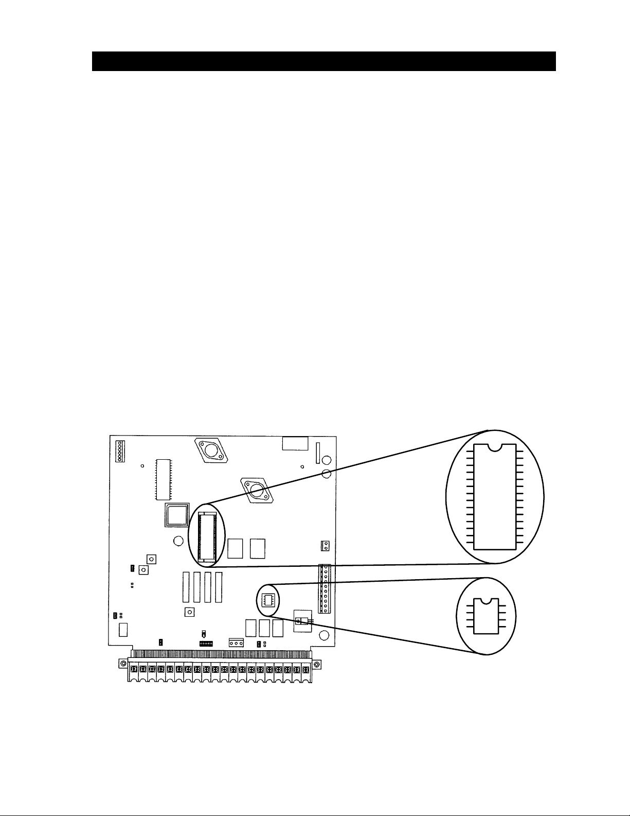
1.2 MEMORY CHIP INSTALLATION
The telephone entry system is shipped with two memory chips packaged in a separate box inside the
shipping container. The memory chips must be installed for the telephone entry system to operate.
CAUTION!! Do not install the memory chips with power to the telephone entry system turned
on. Attempting to install the memory chips with power on will irrevocably damage the chips.
CAUTION!! The memory chips are a static sensitive component. Discharge any static
electricity from your hands by touching a proper ground device before removing the control
board. Handle the memory chips with care.
1. The large memory chip socket is colored black and is located in the center of the circuit
board. Be sure that the handle is in the un-locked position (pointing up). Be sure that
power to the telephone entry system is off.
2. Carefully insert the memory chip into the socket. The small half circular indentation on
the chip must be at the top. CAUTION: Installing the memory chip upside down will
cause permanent damage to the chip. Be sure that the memory chip is seated correctly
in the socket.
3. Move the lever on the chip socket to the locked position (down).
4. Install the small memory chip in the socket located at the bottom of the circuit board. The
small circular indentation on the chip must be at the top. CAUTION: Installing the
memory chip upside down will cause permanent damage to the chip. Be sure that the
memory chip is seated correctly in the socket. If it is necessary to remove this chip, use
a small bladed flat blade screwdriver to carefully pry the chip from the socket. Take extra
caution to be sure to not bend the pins on the chip.
17

1.3 POSTAL LOCK INSTALLATION
At some locations, such as gated communities, it will be necessary to provide access to the mail
carrier so that they can deliver the mail. Mail carrier access will be provided by the installation of an
Arrow Postal Lock. This is the same lock that the Post Office uses for gang mailboxes. These locks
are not available to the public. The installer or the building owner/manager will have to call the Post
Office and arrange for the installation of this lock into the telephone entry system. All DoorKing
commercial telephone entry systems are designed to accept installation of the postal lock.
Prior to installation of the postal lock, be sure power to the telephone entry system is turned off.
1. Remove the hole plug on the faceplate of the telephone entry system.
2. Cut the wire tie wrapped around the micro switch next to the postal lock access hole.
3. Remove the two hex nuts from the postal lock-mounting studs. Mount the postal lock
on the two studs and secure with the hex nuts.
When the lock is installed, check to be sure that the pawl of the lock, in its extended position, is
depressing the micro switch (the micro switch is wired normally closed). When the mail carrier inserts
his key and turns the postal lock, the pawl is withdrawn and the micro switch will activate the relay
that has been programmed for this function for the programmed strike time.
18

SECTION 2 – WIRING
Prior to installing wiring to the telephone entry system, we suggest that you become familiar with the
instructions, illustrations, and wiring guidelines in this manual. This will help insure that you
installation is performed in an efficient and professional manner.
The wiring of the telephone entry panel is an extremely important and integral part of the
overall access control system. Use proper wire for the communication line, power wires, and
be sure that the system is properly grounded. Check all local building ordinances and
building codes prior to installing this system. Be sure your installation is in compliance with
local codes.
If this telephone entry system is used to control a vehicular gate with an automatic gate
operator, the telephone entry system must be mounted a minimum of ten (10) feet away from
the gate and gate operator. If this unit has been installed closer to the automated vehicular
gate, do not proceed with any wiring until the unit has been moved and re-installed so that it is
in compliance with these instructions.
Use only the supplied transformers (or U.L. listed equivalent) to power the telephone entry system
(16.5 VAC, 20 VA for 1803PC and 1815, 16.5 VAC, 40 VA for 1817) and any weigand input devices
(16.5 VAC, 20 VA). Do not power any other devices (electric strikes, magnetic locks, etc.) from these
power transformers. For wire runs up to 100 feet, use 18 AWG, 600 volt insulated wire. For wire
runs up to 200 feet, use 16 AWG, 600 volt insulated wire. Power wires are susceptible to noise and
hum pickup; therefore it is preferable that you keep power wire runs as short as possible.
This telephone entry system contains a number of static sensitive components that can be damaged
or destroyed by static discharges during installation or use. Discharge any static prior to removing
the circuit board from the lobby panel by touching a proper ground device.
Proper grounding of this system is a requirement. The use of surge suppressers can significantly
reduce the chance of component failure because of static charges or surges. To be effective, ground
connections should be made with a minimum 12 AWG, 600 volt insulated wire to a ground point
within 10 feet of the telephone entry system. The ground point must be at an electrical panel, a
metallic cold water pipe that runs in the earth, or a stainless steel grounding rod driven at least ten
(10) feet into the soil.
Be sure that you use proper wire that has an insulation rated for an underground environment. All
wires should be placed in conduits. Proper pre-planning can greatly ease the installation and wiring
of this system. Always check with the local building code to determine the type of wire required in
your municipality.
If Tracker expansion boards are being used with this system, refer to the Tracker Installation and
Wiring manual that came with the Tracker expansion boards, for detailed information on wiring
Tracker boards to the PC programmable telephone entry system.
If Elevator Control is used with this system, refer to the Elevator Control Installation and Wiring
manual for detailed information on wiring the elevator control boards to this system and to the
elevator push button control panel.
19
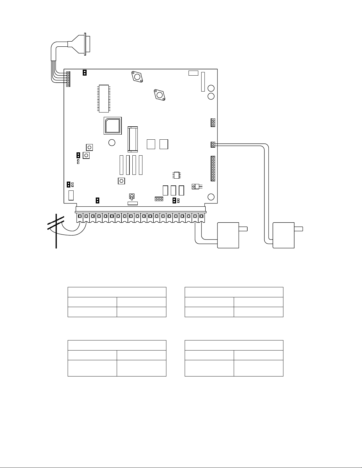
RS-232 Input
(OPTIONAL)
Connections to 2348
Elevator Control Board
(OPTIONAL)
Weigand Power
Inputs for weigand
control devices
(OPTIONAL)
2018 1913 14 15 16 178 9 10 11 123456712
16 VAC
20 VA
16 VAC
20 VA
Power Wiring Maximum Distance
100 Feet 18AWG
200 Feet 16 AWG
Weigand Wiring Maximum Distance
500 Feet Belden 9931
500 Feet Consolidated
5324-CL
Phone Wiring Maximum Distance
800 Feet 24 AWG
1600 Feet 22 AWG
Elevator Control Maximum Wiring
500 Feet Belden 9931
500 Feet Consolidated
5324-CL
20

2.1 MAIN TERMINAL DESCRIPTION
TERMINAL DESCRIPTION
1 Phone Line Connection – 800 ft. maximum with 24 AWG wire; 1600 ft. maximum with 22 AWG wire.
2 Phone Line Connection – 800 ft. maximum with 24 AWG wire; 1600 ft. maximum with 22 AWG wire.
3 Earth Ground Only.
4 Switch Input. A closure between terminals 4 and 6 will cause the designated relay(s) to activate for the
5 Microphone Input.
6 Common for switch input, microphone, speaker, AZ buttons, keyboard and battery negative.
7 Speaker Output.
8 Keyboard Data Input (not used).
9 Keyboard 5 VDC Power (not used).
10 Keyboard Clock Input (not used).
11 Z Button Input.
12 A Button Input.
13 Relay 2 Common – 30 Volt, 3 Amp maximum.
14 Relay 2 Contact (set for normally open or normally closed by the relay contact shorting bar on the circuit
15 Relay 1 Common – 30 Volt, 3 Amp maximum.
16 Relay 1 Normally Closed – 30 Volt, 3 Amp maximum.
17 Relay 1 Normally Open – 30 Volt, 3 Amp maximum.
18 Back-up Battery POSITIVE (connect negative to terminal 6).
19 16 VAC Input Power – 20 VA minimum for 1803PC and 1815; 40 VA minimum for 1817.
20 16 VAC Input Power – 20 VA minimum for 1803PC and 1815, 40 VA minimum for 1817.
programmed strike time. The Postal Switch is connected here.
board) – 30 Volt, 3 Amp maximum.
100 ft. maximum with 18 AWG wire; 200 ft. maximum with 16 AWG wire.
100 ft. maximum with 18 AWG wire; 200 ft. maximum with 16 AWG wire.
Do not run high voltage (115 V) power lines and communication lines in the same conduit. These
should be in separate conduits at least six (6) inches apart. Be sure that all phone line wiring is
twisted and completely isolated from ground.
Use only the supplied 16.5 VAC (or U.L. listed equivalent) to power the entry system. Do not power
any other devices (electric strikes, magnetic locks, lights, etc.) from this transformer. Do not
run 16 VAC entry system power lines over 200 feet. It is advisable to keep these wires as short as
possible. Use 18 AWG wire for wire runs up to 100 feet, and 16 AWG wire for wire runs up to
200 feet. Install a low voltage surge suppresser (DoorKing p/n 1878-010 or equivalent) to help
protect the entry system from power surges. Relay 1 contacts are located on the main terminal strip
(15, 16, 17). Relay 2 contacts are located on the main terminal strip (13, 14) and are set for N.O or
N.C. operation by the relay 2 shorting bar. Relay 0 contacts are located on an auxiliary terminal and
are labeled on the board left to right: NO, NC, C.
A 12 volt .8 amp hour gel-cell battery (DoorKing p/n 1801-008) can be installed in the system to
provide stand-by power in the event of a power outage. Connect the positive (RED) lead to terminal
18; connect the negative (BLACK) lead to terminal 6.
21
 Loading...