

DoorKing 1814 Owner's Manual

Owner’s Manual
Model 1814
Electronic Directory Telephone Entry System
DoorKing, Inc.
120 Glasgow Avenue
Inglewood, California 90301
U.S.A.
Phone: 310-645-0023
Fax: 310-641-1586
www.doorking.com
P/N 1814-065 REV H, 10/01
Copyright 2001 DoorKing, Inc. Al l rights reserved.

2

3
Use this manual with the following models only.
All 1814 models with circuit board 1843-010 REV A and B.
DoorKing, Inc. reserves the right to make changes in the products described in this manual
without notice and without obligation of DoorKing, Inc. to notify any persons of any such revisions
or changes. Additionally, DoorKing, Inc. m akes no representations or warranties with respect to
this manual. This m anual is copyrighted, all rights reserved. No portion of this manual may be
copied, reproduced, translated, or reduced to any electronic m edium without prior written consent
from DoorKing, Inc.

4
TABLE OF CONTENTS
Preface
Important Notices.................................................................................................................................................6
General Information ............................................................................................................................................. 7
Features .............................................................................................................................................................8
Section 1 – Installation
1.1
1.2
1.3
Section 2 – Wiring
General Information
Maximum Wire Run Distance Charts
2.1 Main Terminal Description
2.2
Section 3 – Programming
3.1
3.2
Installation Guidelines – All Systems
1.1.1 Surface Mount Units............................................................................................................. 10
1.1.2 Surface Mount Units with Recess Box.................................................................................. 11
1.1.3 Flush Mount Units.................................................................................................................12
1.1.4 Flush Mount Rough-in Box................................................................................................... 13
1.1.5 Flush Mount Trim Ring.........................................................................................................14
1.1.6 Flush Mount Surface Mounting Kit........................................................................................ 15
1.1.7 Wall Mount Units..................................................................................................................16
Memory Chip Installation
Postal Lock Installation
...........................................................................................................................................19
Re lay Wiring (Typical)
2.2.1 Controlling a Single Door or Gate.........................................................................................22
2.2.2 Controlling a Gate and a Pedestrian Gate or Door................................................................23
Programming Information
3.1.1 Programming from the Keypad............................................................................................. 25
3.1.2 Programming with an IBM Keyboard....................................................................................25
3.1.3 Programming with a Touch-Tone Telephone........................................................................ 25
General Programming
3.2.1 Master Code......................................................................................................................... 26
3.2.2 Single or Multiple Systems ................................................................................................... 26
3.2.3 Programming for Call Up Operation...................................................................................... 26
3.2.4 Relay Strike Time................................................................................................................. 27
3.2.5 Talk Time .............................................................................................................................27
3.2.6 Tone Open Numbers............................................................................................................27
3.2.7 Postal Switch........................................................................................................................ 28
3.2.8 Touch-tone / Rotary-dial....................................................................................................... 28
3.2.9 Rotary-dial 9......................................................................................................................... 28
...............................................................................................9
...................................................................................................................17
.....................................................................................................................18
................................................................................................................20
.................................................................................................................21

5
3.3
3.4
3.5 Four-digit Entry Codes
Programming Letters, Numbers and Messages
3.3.1 Programming Letters and Numbers......................................................................................29
3.3.2 Programming the User Message ..........................................................................................30
3.3.3 Programming the Instruction Message .................................................................................31
Programming Phone Numbers and Names
3.4.1 Programming the Directory Code Length..............................................................................33
3.4.2 Programming 7-digit Phone Numbers ................................................................................... 33
3.4.3 Programming Area Codes ....................................................................................................34
3.4.4 Programming Phone Numbers with Area Codes...................................................................34
3.4.5 Programming Names............................................................................................................35
3.4.6 Deleting Individual Phone Numbers...................................................................................... 35
3.4.7 Delete Names.......................................................................................................................35
3.4.8 Delete Area Codes...............................................................................................................36
3.4.9 Display Phone Numbers.......................................................................................................36
3.5.1 Programming Four-digit Entry Codes....................................................................................37
3.5.2 Delete Four-digit Entry Codes...............................................................................................37
3.5.3 View Four-digit Entry Codes................................................................................................. 37
3.5.4 Entry Code Ranges ..............................................................................................................37
Section 4 – Adjustments
Circuit Board Adjustments.................................................................................................................................... 39
1814 Adjustment Locations..................................................................................................................................41
Section 5 – Operating Instructions
5.1
5.2 Resident Instructions
5.3 System Administrator
5.4 Miscellaneous Operating Instructions
Guest Instructions
5.2.1 Responding to a Guest Call..................................................................................................44
5.2.2 Using an Entry Code.............................................................................................................44
5.3.1 Opening from a Remote Location......................................................................................... 45
5.3.2 Hold Open Command...........................................................................................................45
5.3.3 Relay Check.........................................................................................................................46
5.4.1 Talk Time..............................................................................................................................47
5.4.2 Line Sharing.........................................................................................................................47
5.4.3 Connection to a PBX ............................................................................................................47
5.4.4 10-digit Dialing......................................................................................................................47
..............................................................................................................................43
Section 6 – Maintenance and Trouble Shooting
6.1 Trouble Shooting..................................................................................................................................49
6.2 Accessories..........................................................................................................................................53
6.2 Log Tables ........................................................................................................................................... 54
Resident Instruction Sheet...................................................................................................................................57
......................................................................................32

6
IMPORTANT NOTICE
FCC - UNITED STATES
This equipment has been tested and found to comply with the limits for a class A digital device,
pursuant to Part 15 of the FCC Rules and Regulations. These limits are designed to provide
reasonable protection against harm ful interference when the equipment is operated in a commercial
environment. This equipment generates, uses, and can radiate radio frequency energy and, if not
installed and used in accordance with the instruc tion m anual, m ay cause harm ful inter fer ence to radio
communications. Operation of this equipment in a residential area is likely to cause harmful
interference in which case the user will be required to correct the interference at his own expense.
FCC Registration Number:
DOC - CANADA
The Canadian Department of Com munications label identifies certified equipment. This certification
means that the equipment meets certain telecommunications network protective, operational, and
safety requirements. The Department does not guarantee the equipment will operate to the users
satisfaction.
Before installing this equipment, users should ensure that it is permissible to be connected to the
facilities of the local telecom munications company. The equipment must also be installed using an
acceptable means of connection. The customer should be aware that compliance with the above
conditions may not prevent degradation of service in some situations.
Repairs to certified equipment should be made by an authorized Canadian maintenance facility
designated by the supplier. Any repairs or alterations made by the user to this equipment, or
equipment malfunctions, may give the telecommunications company cause to request the user to
disconnect the equipment.
Users should ensure, for their own protection, that the electrical ground connections of the power
utility, telephone lines, and internal metallic water pipe system, if present, are connected together.
This precaution may be particularly important in rural areas.
CAUTION: Users should not attem pt to make such connections them selves, but should contact the
appropriate electric inspection authority, or electrician, as appropriate.
DOC Registration Number:
Notice:
The Load Number (LN) as signed to each terminal device denotes the percentage of the total load to
be connected to a telephone loop which is used by the device, to prevent overloading. The
termination on a loop may consist of any combination of devic es subject only to the requirement that
the sum of the load numbers of all the devices does not exceed 100.
Notice:
DoorKing does not provide a power transform er on units s old into Canada. Use only transformers that
are CSA listed to power the telephone entry system. 1802, 1803, 1808, 1810, 1814, 1815, 1818 and
all "P" series systems require a 16.5-volt, 20 VA tr ansformer. The m odels 1816 and 1817 require a
16.5-volt, 40 VA transformer. The model 1812 requires a 24-volt, 20 VA transformer.
DUF6VT-12874-OT-T
1736 4528 A

7
GENERAL INFORMATION
•
Prior to beginning the installation of the telephone entry system, we suggest that you become
familiar with the instructions , illustrations, and wiring guidelines in this manual. This will help
insure that you installation is performed in an efficient and professional manner.
•
The proper installation of the telephone entry panel is an extremely important and integral
part of the overall access control system. Check all local building ordinances and building
codes prior to installing this system. Be sure your installation is in compliance with local
codes.
•
When used to control a door or pedestrian gate, try to locate the telephone entry system as
near as possible to the entry point. The unit should be mounted on a rigid wall to prevent
excessive shock and vibration from closing doors or gates. Continuous vibration and shock
from slam m ing doors or s pring-loaded pedestr ian gates will dam age the circuit boar d.
no circumstances should the unit be mounted directly to a moving door or gate
•
ADA mounting requirements for door control.
way that the LCD display is positioned so that it is readily visible to and usable by a person
sitting in a wheelchair with an approxim ate eye level of 45 inches and shall comply with the
following requirements:
1. If mounted vertically or tipped no more than 30 degr ees away from the viewer, the
center line of the LCD
2. If the clear floor space allows only forward approach to the system, the maximum
high forward reach allowed is 48 inches above grade to the top of the keypad.
3. If the high forward reach to the system is over an obstruction of greater than 20
inches but less than 25 inches , the maximum high f or ward reac h allowed is 44 inches
above grade to the top of the keypad.
4. If the clear floor space allows parallel approach by a person in a wheelchair, the
maximum high side reach shall be 54 inches above grade to the top of the keypad.
5. If the high side reac h is over an obstruction of 24 inches or less, the max imum high
side reach allowed is 46 inches above grade to the top of the keypad.
•
When used to control a vehicular gate with an automatic gate operator, the telephone
entry system must be mounted a minimum of ten (10) feet away from the gate and gate
operator, or in such a way that a person cannot operate the entry syst em and/or touch
the gate or gate operator at the same time
Under
.
The mounting of the unit shall be in s uch a
shall be located a maximum of 52 inches above grade.
.
•
Be sure that the system is installed so that it is not directly in the traf fic lane. Goose neck
mounting post and kiosk s work well for these type systems. W hen planning where to locate
the system, take into consideration traf fic lane layouts, turn around lanes for rejected access,
conduit runs, power availability, etc.
•
Environmental factors m ust also be tak en into ac count. Surfac e mount units are designed for
direct outdoor installations, however it is preferable to protect them from direct exposure to
driven rain or snow whenever possible. Flush m ount and wall mount units must be pr otected
from direct ex posure to the elements. Be sure that ample lighting is provided so that guest
can read both the directory and the operating instructions at night.
•
This telephone entry system contains a number of static sensitive components that can be
damaged or destroyed by static discharges during installation or use. Discharge any static
prior to removing the circuit board from the lobby panel by touching a proper ground device.

8
FEATURES
•
Can provide service for up to 3000 residents.
•
System keypad will emit DTMF tones after a call is answered allowing the system to be used
with auto-attendants, answering machines, etc.
following units only
Model 1814 with 1843-010 circuit board, REV B or higher.
•
Directory codes can be set from 1 to 4 digits in length and can be randomly assigned.
•
10 programmable ar ea codes allow the system to be used in areas requiring 10 and 11-digit
dialing.
•
Two internal relays allow the system to control a main entry point plus an additional entry
point.
•
Large A and Z scroll buttons provide an easy method to locate names in the electronic
directory. Buttons can be held to scroll through the directory rapidly, or pressed and released
to scroll one name at a time.
•
All name searches start in the middle of the database to reduce scroll time.
•
“One Touch” Call button allows users to initiate a call without having to enter a directory code
on the system keypad.
:
This feature is available with the
•
Backlit super-twist LCD uses large ½-inch characters that are easy to read.

9
SECTION 1 - INSTALLATION
Order your telephone line at least two weeks prior to the planned installation date. This will assure
that a phone line is available when the unit is installed. The telephone company will require the
following information from you:
Type: Touch Tone, Loop Start
Ringer Equivalence: 0.0 A
Jack Type: RJ11C
FCC Registration (US): DUF6VT-12874-OT-T
DOC (Canada): 1736 4528 A
Electrical Listing: Complies with U.L. 294 - ETL Listed
CALLER ID
the entry system phone line. Without caller ID bloc king, tenants with the proper phone equipment will
be able to identify the telephone num ber that the entry system is installed on. This m ay or may not
be desirable.
: You may want to consider ordering caller ID blocking fr om the telephone company for
1.1 INSTALLATION GUIDELINES – ALL SYSTEMS
1. O pen the cabinet of the telephone entry system and disconnect the keypad ribbon cable
from the main circuit board.
2. Remove the 6-32 x 1/2 round head screws from the upper corners of the circuit board.
3. Remove the circuit board by gently pulling it out of the main terminal edge connector.
CAUTION
electricity from your hands by touching a proper ground device before removing the
circuit board. Place the circuit board where it will not be damaged.
4. Mount the cabinet of the telephone entry system. Be sure that m ounting screws do not
protrude into the cabinet where they could cause a short on the back of the circuit board.
Make any necessary conduit connections.
5. Route wiring into the cabinet. Do not apply any power at this time.
6. Clean out the cabinet. Be sur e that all dir t, metal and/or wood debris is removed f r om the
cabinet and that the terminal strip edge connector is clean and free of any loose particles.
7. Re-install the c ircuit board into the cabinet by gently pushing the circuit board terminals
into the edge connector.
components. Discharge any static electricity from your hands by touching a proper
ground device before removing the circuit board.
8. Secure the circuit board to the cabinet using the screws removed in step 2.
9. Plug the keypad ribbon cable into the circuit board. The cable points down.
- the circuit board contains static sensitive com ponents. Discharge any static
CAUTION
- the circuit board contains static sensitive
10
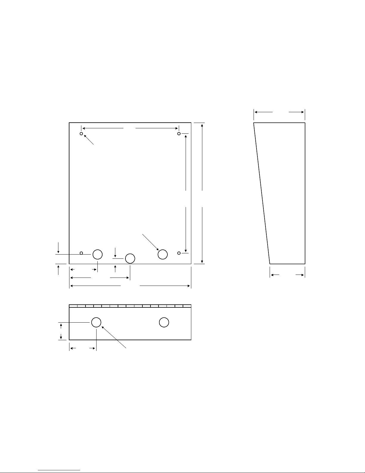
1.1.1 Surface Mount Units
Surface mount units can be mounted directly to a wall or pilaster, or c an be post mounted using a
DoorKing heavy-duty mounting post (p/n 1200-047 and 1200-048). Be sure the unit is mounted
securely and is not subject to vibration from closing doors or gates.
CAUTON!
entry system must be mounted a minim um of ten (10) feet away from the gate and gate operator, or
in such a way that a person cannot operate the entry system and touch the gate or gate operator at
the same time.
If this entry system is used to control a vehicular gate with an automatic gate operator, the
4.75
9.0
.25 DIA
.875
1.625
2.625
2.5
5.625
.875 DIA
.5
11.25
.875 DIA
11.0
13.0
3.25
11
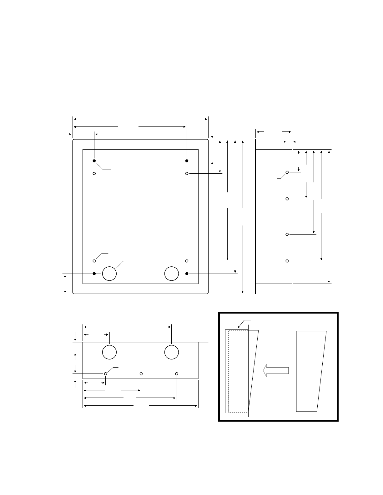
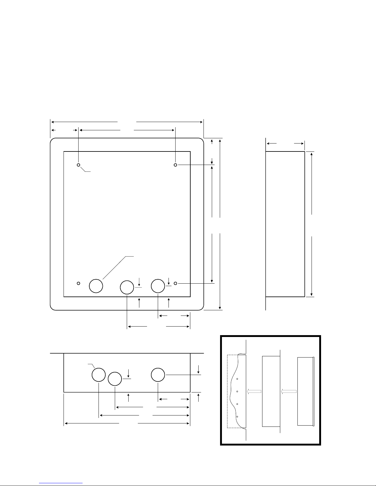
1.1.2 Surface Mount Units with Recess Box
Surface mount units can be sem i-flush mounted into a wall or pilaster by using the optional recess mounting box (p/n 1803-150). Be sur e the unit is mounted securely and is not subject to vibration
from closing doors or gates.
CAUTON!
entry system must be mounted a minim um of ten (10) feet away from the gate and gate operator, or
in such a way that a person cannot operate the entry system and touch the gate or gate operator at
the same time.
If this entry system is used to control a vehicular gate with an automatic gate operator, the
15.00
11.125
2.125
2.125
3.625
.5
2.0
3.375
10-24 x 1.25 STUD
.25 DIA
12.0
13.25
15.25
.25 DIA
1.375 DIA
1803-150
1.06.5
2.68
8.812
Recess Box
2.25
4.875
8.375
Surface Mount
Entry System
11.0
13.25
.25 DIA
2.2
5.75
9.3
11.5
12
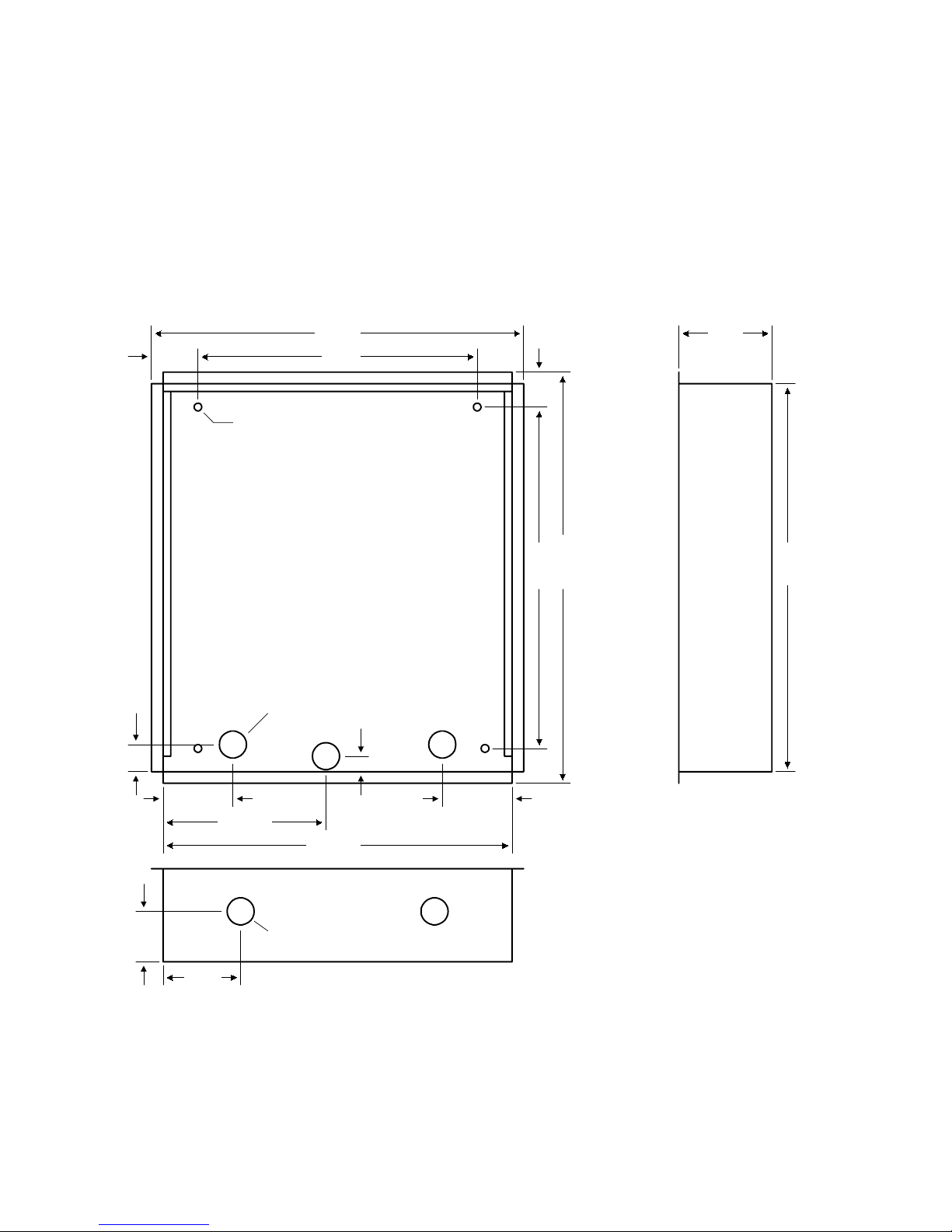
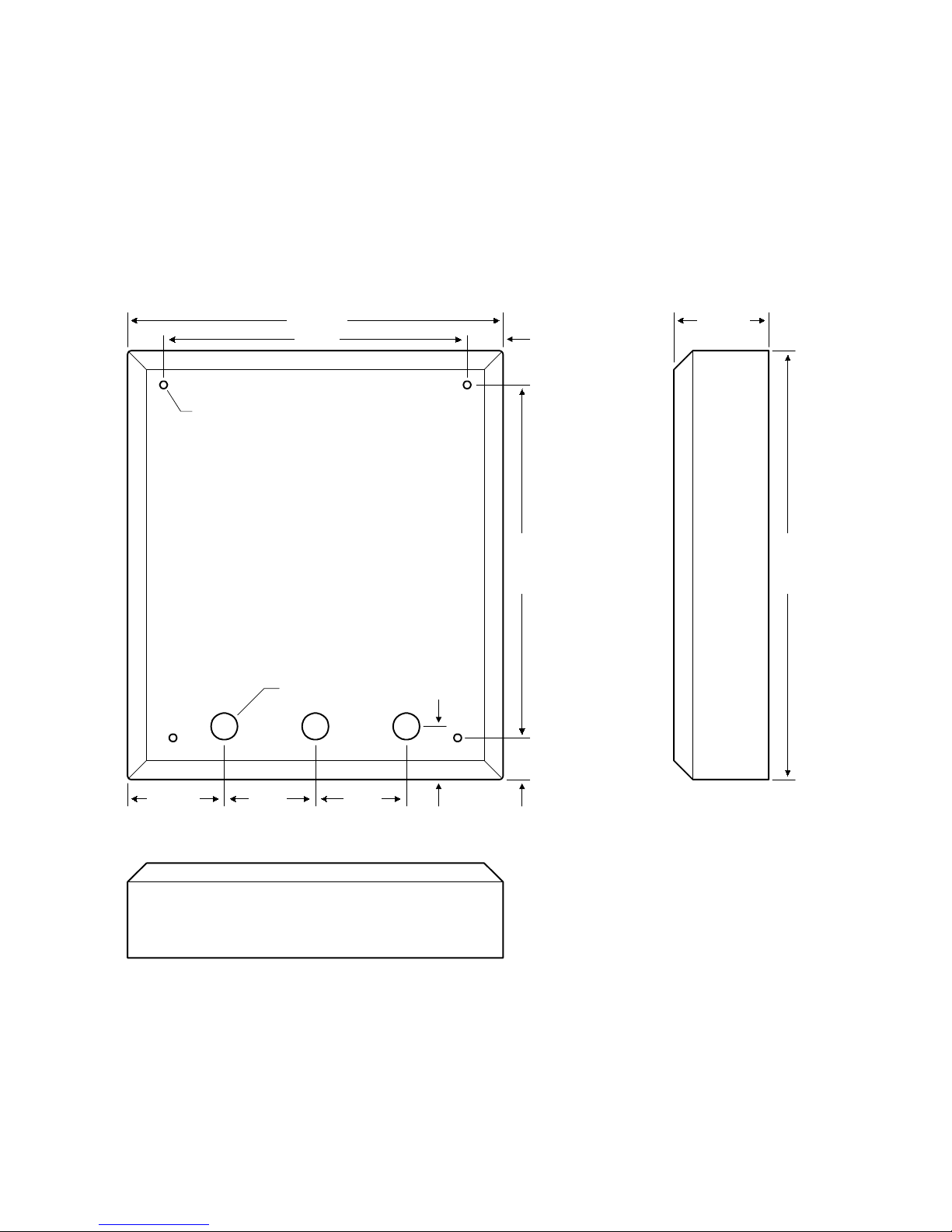
1.1.3 Flush Mount Units
Flush mount units are installed into a wall with flush mount kits 1814-065 (stainless) or 1814-066
(gold). Flush mount kits are not included with the entry system. Flush mount units are not designed
for direct exposure to the weather. Be sure the unit is mounted securely and is not subject to
vibration from closing doors or gates.
CAUTON!
entry system must be mounted a minim um of ten (10) feet away from the gate and gate operator, or
in such a way that a person cannot operate the entry system and touch the gate or gate operator at
the same time.
If this entry system is used to control a vehicular gate with an automatic gate operator, the
1.125
.875
.25 DIA
.875 DIA
12.0
9.0
.50
13.25
11.0 1.125
3.0
13.0
2.625 2.625
5.625
.875 DIA
1.625
2.5
11.25
13
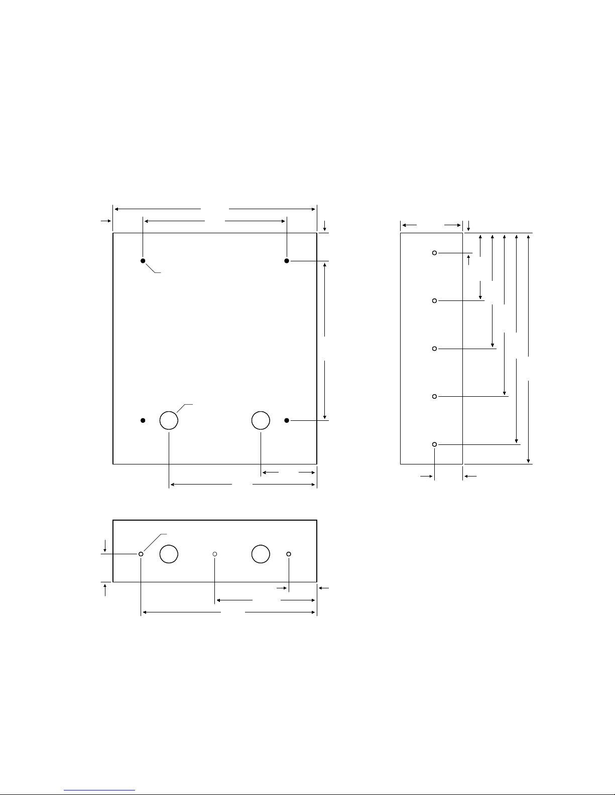
1.1.4 Flush Mount Rough-in Box
The flush mount ins tallation kit has two parts; the rough-in box and the trim ring. The rough-in box is
installed first.
1.875
12.75
9.0
10-24 x 1.125 Stud
1.125 DIA
9.25
3.5
11.0 1.75
3.875
1.25
4.25
7.25
10.25
13.25
14.5
1.75
.25 DIA
1.75
1.75
6.375
11.0
14
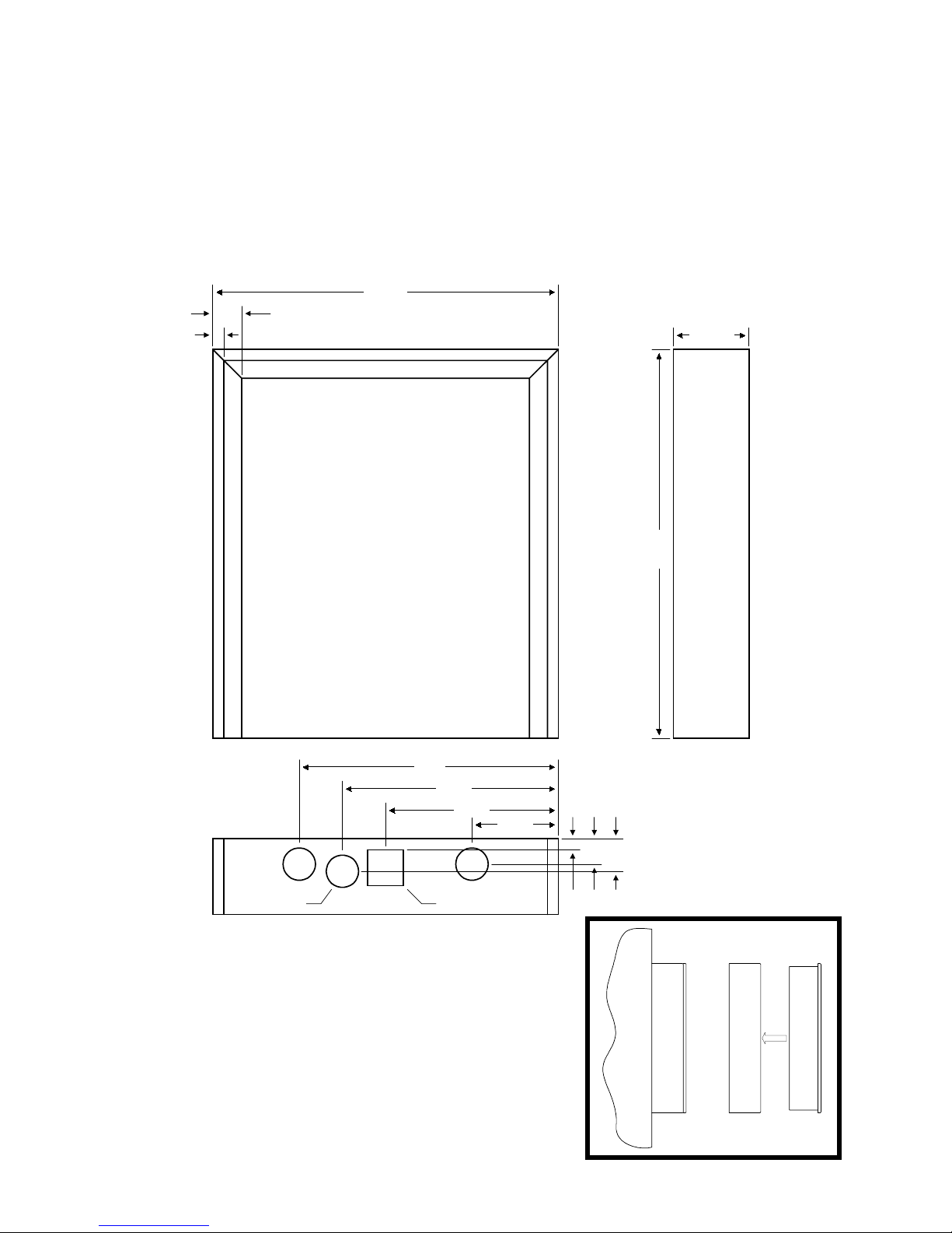
1.1.5 Flush Mount Trim Ring
Flush mount units can be m ounted by using the 1814-065 (stainles s) or 1814-066 (gold) m ounting k it.
Flush mounting kits are not included with the unit. Flush mount units are not designed for direct
exposure to the weather. Be sure the unit is mounted securely and is not subject to vibration from
closing doors or gates.
CAUTON!
entry system must be mounted a minim um of ten (10) feet away from the gate and gate operator, or
in such a way that a person cannot operate the entry system and touch the gate or gate operator at
the same time.
If this entry system is used to control a vehicular gate with an automatic gate operator, the
14.25
2.625 9.0
3.625
.25 DIA
1.25 DIA
1.125
11.75
1.25 DIA
.875
5.875
7.0
8.5
1.0
3.0
3.0
1.625
11.0 2.25
16.0
Rough-in
Box
Trim
Ring
Flush Mount
Entry System
13.625
15
1.1.6 Flush Mount Surface Mounting Kit
Flush mount units can be surface m ounted by using the optional 1814-152 surface mount trim ring.
Flush mount units are not designed for direct exposure to the weather. Be sure that the unit is
securely mounted and is not subject to vibration from closing doors or gates.
CAUTON!
entry system must be mounted a minim um of ten (10) feet away from the gate and gate operator, or
in such a way that a person cannot operate the entry system and touch the gate or gate operator at
the same time.
If this entry system is used to control a vehicular gate with an automatic gate operator, the
12.0
1.0
.375
2.625
9.0
7.5
6.0
1.125 DIA 1.125 SQ
3.0
.375
.875
1.125
13.5
1814-152
Trim Ring
Flush Mount
Entry System
16
1.1.7 Wall Mount Units
Wall mount units (models 1815 and 1817 only) are designed to be mounted directly onto a wall
without the need of cutting a large hole as is necessary with flush m ount units. W all mount units are
not designed for direct exposure to the weather. Be sure the unit is mounted securely and is not
subject to vibration from closing doors or gates.
CAUTON!
entry system must be mounted a minim um of ten (10) feet away from the gate and gate operator, or
in such a way that a person cannot operate the entry system and touch the gate or gate operator at
the same time.
If this entry system is used to control a vehicular gate with an automatic gate operator, the
.25 DIA
12.375
10.0 1.187
.875 DIA
1.75
11.6251.375
3.125
14.125
3.0 3.03.187
17
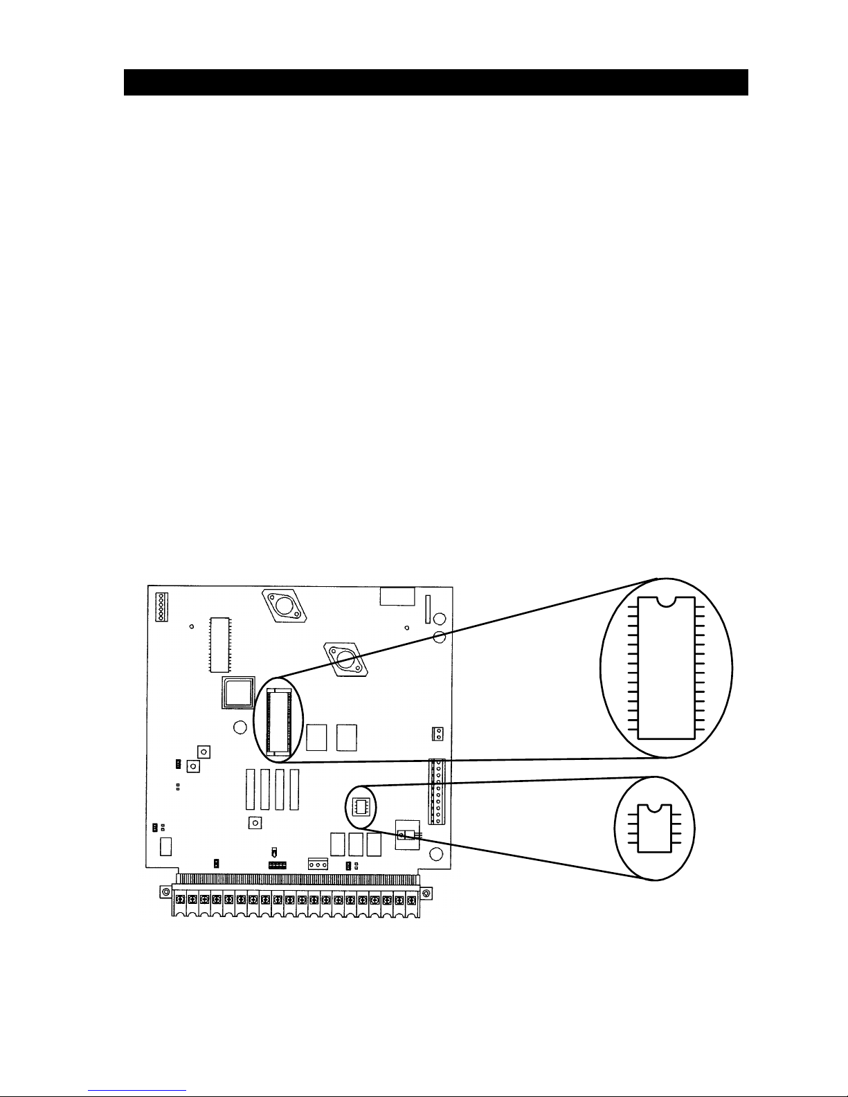
1.2 MEMORY CHIP INSTALLATION
The telephone entry system is s hipped with two mem ory chips packaged in a separ ate box inside the
shipping container. The memory chips must be installed for the telephone entry system to operate.
CAUTION!! Do not install the memory chips with power to the telephone entry system turned
on. Attempting to install the memory chips with power on will irrevocably damage the chips
CAUTION!! The memory chips are a static sensitive component. Discharge any static
electricity from your hands by touching a proper ground device before removing the control
board. Handle the memory chips with care
1. The lar ge memory chip socket is colored black and is located in the center of the circuit
board. Be sure that the handle is in the un-locked pos ition (pointing up). Be sure that
power to the telephone entry system is off.
2. Carefully insert the memory chip into the sock et. The small half circular indentation on
the chip must be at the top. CAUTION: Installing the memory chip upside down will
cause permanent dam age to the chip. Be sure that the memory chip is seated correctly
in the socket.
3. Move the lever on the chip socket to the locked position (down).
4. Install the small memory chip in the soc ket located at the bottom of the circ uit boar d. T he
small circular indentation on the chip must be at the top. CAUTION: Installing the
memory chip ups ide down will c ause permanent damage to the chip. Be sure that the
memory chip is seated cor rectly in the socket. If it is nec essary to remove this chip, use
a small bladed flat blade screwdriver to caref ully pry the chip from the s ock et. Take extr a
caution to be sure to not bend the pins on the chip.
.
.

18
1.3 POSTAL LOCK INSTALLATION
At some locations, such as gated communities, it will be necessary to provide access to the mail
carrier so that they can deliver the mail. Mail car rier access will be provided by the installation of an
Arrow Postal Lock . T his is the sam e lock that the Post Of fice uses for gang m ailboxes. T hese lock s
are not available to the public. The installer or the building owner/m anager will have to call the Post
Office and arrange for the installation of this lock into the telephone entry system. All DoorKing
commercial telephone entry systems are designed to accept installation of the postal lock.
Prior to installation of the postal lock, be sure power to the telephone entry system is turned off.
1. Remove the hole plug on the faceplate of the telephone entry system.
2. Cut the wire tie wrapped around the micro switch next to the postal lock access hole.
3. Remove the two hex nuts from the pos tal lock -m ounting s tuds. Mount the postal lock
on the two studs and secure with the hex nuts.
When the lock is installed, check to be sure that the pawl of the lock, in its extended position, is
depressing the m icr o s witch (the micro switch is wired norm ally closed). When the m ail car r ier ins ert s
his key and turns the postal lock, the pawl is withdrawn and the mic ro switch will activate the relay
that has been programmed for this function for the programmed strike time.
 Loading...