

DoorKing 1803, 1808, 1810 Installation & Owner's Manual
Installation/Owner’s Manual
1803 / 1808 / 1810
1810
1803
1808
7
8
9
4
5
6
1
2
3
0
P
u
sh
B
u
t
t
o
n
T
o
C
a
l
l
7
8
9
4
5
6
1
2
3
0
N
A
M
E
Ad
a
m
s
J
Be
rna
rd
E
Bro
wn
L
D
a
v
i
s
T
H
o
d
g
e
s
S
M
il
l
e
r
J
Sm
i
th
K
T
h
o
m
a
s
W
Z
i
m
m
e
r
R
1
9
5
2
4
6
8
3
7
C
ODE
7
8
9
4
5
6
1
2
3
0
a
r
I
rl
i
n
J
r
n
a
r
d
E
l
l
i
n
g
s
L
r
o
k
e
r
T
B
r
o
s
e
S
B
r
o
w
n
J
B
r
o
w
n
K
B
ry
a
n
t
W
B
y
r
o
n
R
B
y
a
n
G
6
5
6
0
7
8
2
2
1
3
2
1
2
4
9
4
7
6
0
0
3
1
1
2
2
9
2
8
2
2
4
9
1
3
2
4
2
3
1
3
3
2
1
1
7
C
a
r
n
e
y
P
C
o
l
l
i
n
s
G
C
o
l
y
e
r
R
C
o
rd
u
l
a
D
C
o
u
rt
E
C
rai
n
s
G
Da
l
to
n
B
Da
n
i
e
l
s
R
Da
w
l
s
J
D
e
L
a
h
a
e
M
D
i
l
l
P
Di
l
l
o
n
M
D
i
x
o
n
D
Do
m
i
n
i
c
k
P
D
o
n
i
c
k
P
Do
n
n
e
r
K
Do
n
t
e
r
F
2
1
1
6
7
0
4
4
1
7
8
9
4
5
6
1
2
3
0
e
s
s
C
o
d
e
N
u
m
b
e
r
.
I
f
L
i
n
e
I
s
Bu
s
y
,
P
r
es
s
A
n
y
B
u
tt
o
n
n
t
er
O
n
“
O
P
E
N
”
D
i
s
p
la
y
o
r
T
o
n
e.
e
J
s
o
n
H
g
a
t
e
B
n
D
b
a
u
g
h
B
s
J
a
r
I
r
l
i
n
J
rn
a
rd
E
l
l
i
n
g
s
L
r
o
k
e
r
T
B
ro
s
e
S
B
ro
w
n
J
B
ro
w
n
K
B
ry
a
n
t
W
B
y
r
o
n
R
B
y
a
n
G
0
0
9
1
1
5
3
5
2
5
5
1
6
5
6
0
7
8
2
2
1
3
2
1
2
4
9
4
7
6
0
0
3
1
1
2
2
9
2
8
2
2
4
9
1
3
2
4
2
3
1
3
3
2
1
1
7
C
OD
E
N
A
M
E
B
y
e
rs
M
C
a
rd
i
l
l
o
P
C
a
r
n
e
y
P
C
o
l
l
i
n
s
G
C
o
l
y
e
r
R
C
o
r
d
u
l
a
D
C
o
u
rt
E
C
ra
i
n
s
G
D
a
l
t
o
n
B
D
a
n
i
e
l
s
R
D
a
w
l
s
J
De
L
a
h
a
e
M
Di
l
l
P
D
i
l
l
o
n
M
Di
x
o
n
D
Do
m
i
n
i
c
k
P
D
o
n
i
c
k
P
Do
n
n
e
r
K
Do
n
t
e
r
F
8
0
7
5
0
3
5
0
1
4
0
4
4
6
1
2
4
9
7
7
2
6
3
3
4
8
1
1
0
4
3
2
2
0
6
8
8
8
8
5
1
8
3
5
8
4
6
7
C
O
D
E
N
A
M
E
D
o
r
l
a
n
d
T
D
o
w
n
w
a
rd
L
2
1
1
5
4
3
9
8
7
3
5
2
W
a
s
h
i
n
g
t
o
n
G
W
a
s
h
i
n
g
t
o
n
K
W
e
n
t
L
W
h
i
t
i
n
g
M
W
i
n
s
t
o
n
F
W
y
a
t
t
J
2
1
3
2
2
9
0
0
7
1
3
4
6
0
9
3
8
9
6
7
9
2
1
1
6
7
0
4
4
1
7
8
9
4
5
6
1
2
3
0
7
8
9
4
5
6
1
2
3
0
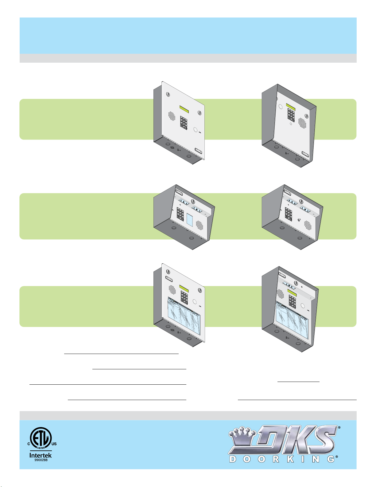
1803 / 1808 / 1810
1803 / 1808 / 1810
Telephone Entry System
Use this manual for circuit board 1862-010 Revision O or higher.
Flush Mount
TELEPHONE
ENTR
1
2
4
5
7
8
1803
1803
0
O
1.
PE
Loca
R
2.
ATI
te
P
r
C
e
ode
N
s
s
P
G
C
r
e
ode
Number
I
3.
s
N
s
En
S
“
N
#
te
u
”
m
r on To
to
on
ber
H
.
ang
If
n
e
UP
.
. T
1803-084
Surface Mount
with Directory
1
2
3
4
5
7
6
8
9
0
1808
1808
1800-060 Issued 7-19
Control a main entry point plus an additional entry point.
Surface Mount
TELEPHONE
ENTRY
S
YSTEM
1
2
3
4
Y
SYSTEM
3
6
9
TR
U
CTI
Direc
O
Line
to
N
r
S
y.
is Bu
r
y
A
s
g
y,
ain.
7
OPE
1.
Locate C
R
2.
ATI
P
r
es
o
N
s
de Num
P
C
r
es
ode
3.
s
Ent
“#”
Nu
e
m
r on
to
H
Ton
a
e
.
1803-080
5
6
8
9
0
G
I
NST
b
er
R
on
ber
U
CT
D
.
ire
If
ng
I
O
Line
c
UP
to
NS
r
.
y.
is
T
r
y
B
Again.
usy,
M
ODEL
180
Surface Mount
1
2
3
4
5
7
6
N
A
M
E
Ad
a
m
C
s
Be
ODE
J
rna
rd
Bro
E
wn
1
D
L
a
v
i
9
s
T
H
o
d
5
g
e
M
s
S
il
l
e
2
r
Sm
J
i
th
4
T
K
h
o
m
6
a
Z
s
i
m
W
m
8
e
r
R
3
7
Pu
8
s
h
Butt
9
To
0
o
Ca
n
l
l
3
1810
1810
Date Installed:
Installer/Company Name:
Phone Number:
Leave Manual with Owner
1808-082
Flush Mount
1
2
3
4
5
7
6
8
1
2
3
NA
M
E
B
e
j
a
r
B
e
rl
i
n
B
e
r
n
B
i
l
l
i
n
B
r
o
k
B
r
o
B
r
o
B
r
B
ry
B
B
1810-084
Copyright 2019 DoorKing®, Inc. All rights reserved.
9
0
C
a
r
n
e
y
P
6
C
5
o
6
I
l
l
i
n
s
G
0
C
7
o
8
l
J
y
e
r
R
2
C
2
a
o
1
r
rd
d
u
E
l
a
3
D
C
2
g
o
1
s
u
rt
L
E
2
C
4
e
rai
9
r
T
n
s
G
4
s
Da
7
e
6
l
S
to
n
B
0
w
Da
0
n
3
n
J
i
e
l
s
o
1
R
w
Da
1
n
2
w
K
l
s
J
2
a
D
9
n
e
2
t
L
W
a
h
a
y
e
r
8
o
D
2
M
n
i
2
l
l
R
P
y
a
4
Di
n
9
1
G
l
l
o
n
M
3
D
2
i
4
x
o
n
D
2
Do
3
1
m
i
n
i
c
3
k
D
3
P
o
2
n
i
c
k
P
1
Do
1
7
n
n
e
r
K
Do
n
t
e
r
F
2
1
1
6
7
0
4
4
1
Circuit Board
Serial Number
and Revision Letter:
Model Number
1808-084
Surface Mount
1
2
3
4
5
7
6
8
1
2
.
P
re
s
3
.
E
n
t
A
n
n
e
s
e
A
n
d
e
r
s
o
A
p
p
l
e
g
A
u
s
t
i
n
B
a
l
s
b
a
B
a
s
s
B
e
j
a
r
B
e
r
l
i
B
e
rn
B
i
l
l
i
B
r
o
B
ro
B
ro
B
ro
B
B
1810-080
9
0
s
C
o
d
e
N
u
m
er
b
e
O
r
.
n
I
“
f
O
L
P
i
n
E
e
N
I
”
s
D
Bu
i
s
s
p
y
la
,
y
P
r
o
es
r
T
J
s
N
C
o
A
OD
A
M
n
n
E
e.
E
y
n
D
B
o
H
u
r
0
N
l
a
tt
0
A
n
9
M
o
d
a
t
n
E
T
D
e
o
B
w
1
B
1
n
y
5
w
e
D
rs
a
rd
M
L
3
C
5
a
2
rd
u
g
i
l
h
l
o
B
P
5
C
5
a
J
1
r
n
e
y
P
6
C
5
C
o
6
O
I
l
l
D
i
n
E
s
G
0
C
7
n
o
8
l
J
8
y
0
e
7
r
R
2
C
2
a
o
1
rd
r
5
d
0
u
E
3
l
a
3
D
C
n
2
g
o
1
s
u
5
rt
0
L
1
E
2
k
C
4
e
ra
9
r
4
i
T
n
0
s
4
G
4
s
D
7
e
a
6
l
S
4
t
o
6
n
1
B
0
w
D
0
a
n
3
n
2
J
i
4
e
9
l
s
1
R
w
D
1
a
n
2
w
7
K
7
l
s
2
ry
J
2
a
De
9
n
2
t
L
6
W
a
3
h
3
a
y
e
r
8
o
Di
2
M
n
2
l
l
4
R
P
8
B
1
y
a
4
D
n
9
G
i
1
l
l
1
o
0
n
4
M
3
Di
2
4
x
3
o
2
n
2
D
2
Do
3
1
m
0
6
i
n
8
i
c
3
k
D
3
P
o
2
n
8
i
8
c
8
k
P
1
Do
1
7
n
5
n
1
e
8
r
K
Do
n
3
t
5
e
8
r
F
4
6
7
W
a
2
s
1
h
3
i
n
2
g
1
W
t
1
o
a
n
2
s
G
2
h
9
i
n
5
g
4
W
t
3
o
e
n
0
n
K
0
t
7
L
9
8
W
7
h
1
i
t
3
i
n
4
g
3
5
M
W
2
i
n
6
s
0
t
9
o
n
W
F
y
3
a
8
t
t
9
J
6
7
9
2
1
1
6
7
0
4
4
1
Version A
Conforms To UL STD 294
Certified To CAN/ULC-S319-05
UL Listed
Copyright 2009 DoorKing, Inc. All rights reserved.
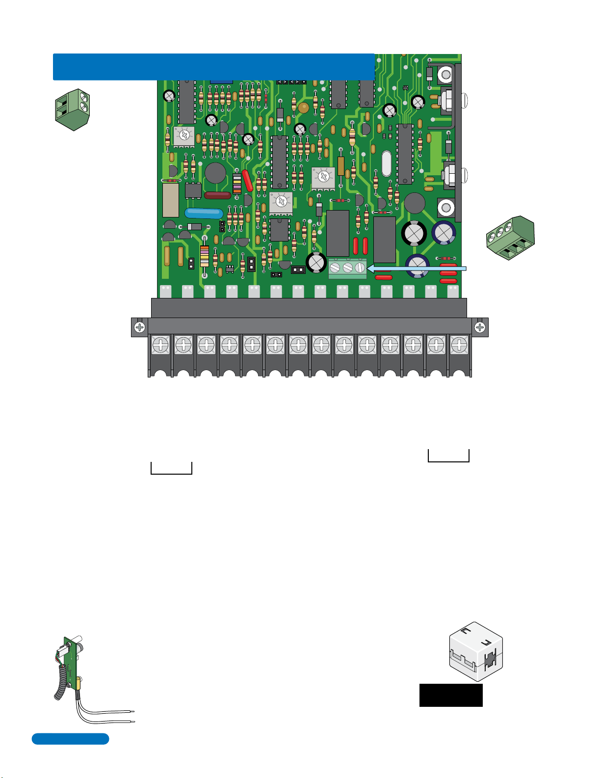
QUICK GUIDE: Terminal Descriptions
1
Located in the
2
upper left corner
of circuit board.
CLCK
SENSE
KEYPAD
Switch Input 2
Terminal
Non-Removable
A closure between these
terminals will cause Relay 2
to activate for the
programmed strike time or
dial a preprogrammed
phone number (see section
3.1.7).
321
MIC VOL
FEEDBACK
321
SPK
321
VOL
HF
HS
NC C
NO
RING
TONE
ON
TONE
OFF
Main Terminal
BAT NC NO
MIC
SPKR COMMICGPSWCGNDPHONE
C
1234567891011121314
Phone Line Connection
Ring
Phone Line Connection
Tip
Earth Ground Only (See Section 2.1.3). NOT a low voltage common.
Switch Input 1. A closure between terminals 4 and 8 will cause Relay 1 to activate for the
programmed strike time or dial a preprogrammed phone number – see section 3.1.7.
Postal Switch connection.
Microphone ground Input (White Wire).
Speaker Output (Purple Wire).
Microphone Input (Green Wire).
Common for Switch Input 1 terminal #4, speaker, Standby Battery NEGATIVE
Standby Battery POSITIVE (12 VDC, .7 Ah, SLA) (connect negative to terminal 8)
Relay 1 Normally Closed – 30 Volt, 3 Amp max.
Relay 1 Common
Relay 1 Normally Open – 30 Volt, 3 Amp max.
16AC16AC
16 VAC Input Power
20 VA Minimum
Normally Open – 30 Volt, 3 Amp max.
Normally Closed – 30 Volt, 3 Amp max.
Common – 30 Volt, 3 Amp max.
C
NC
NO
Relay 2 Terminal
Non-Removable
16 VAC Input Power
2
Quick Guide - 1
UL 294
Tamper
Switch
Located under
microphone board
(See Section 1.7).
800 ft. max. with 24 AWG wire.
1600 ft. max. with 22 AWG wire.
(Wiring MUST be twisted and isolated from the ground)
100 ft. max. with 18 AWG wire.
200 ft. max. with 16 AWG wire.
Install ferrite filter on these wires - see section 2.1.5.
Ferrite
Filter
Do Not Connect Power
To A Receptacle
Controlled By A Switch.
See page 21 for terminal wiring.
1800-060 Issued 7-19
Version A
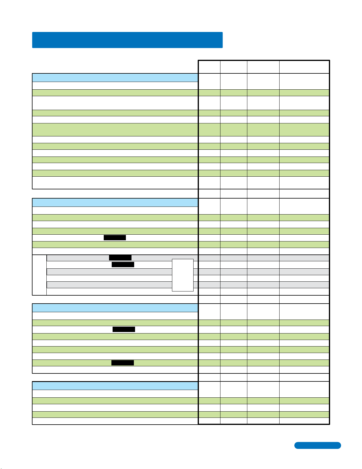
Overview for System Programming
Section 3.1 General Programming
Master Code
Single or Multiple Systems
Relay Strike Time
“Tone Open” Sound ON or OFF
Talk Time
Tone Open Numbers
Programming Switch Input 1 and Switch Input 2
Number of Rings Before Telephone Entry System will Answer
PBX Line Access Code Programming
Star Key (*) Function
Keypad Function (DTMF Programming)
System to Stay On-Line or Hang-Up after Touch-Tone Number Pressed
Automatic Hang-Up Function
Section 3.2 Directory Code and Phone Number Programming
Programming the Directory Code Length
# Key - Insert an Amount of “Pause Time” Between Phone Number Digits
Programming Phone Numbers - Up to 16-Digits
Deleting Individual Phone Number
Deleting ALL Phone Numbers
Display / DELETE Phone Numbers with UNKNOWN Directory Codes
Display Phone Numbers with KNOWN Directory Codes
7-Digit Phone Number Capability
16-Digit Phone Number Capability CAUTION
Programming 7-Digit Phone Numbers
Programming Area Codes (Area Code Reference Numbers)
Programming Phone Numbers WITH Area Code Reference Numbers
- Limited Use -
7-Digit Phone #
Deleting Individual 7-Digit Phone Number
CAUTION
CAUTION
These
sections are
NOT used for
Factory Set
16-Digit
Phone Number
Programming
Page # Factory Setting
Section Command
24
26
26
26
26
27
27
27
28
28
28
28
29
30
30
31
31
32
32
32
33
33
34
34
35
35
3.1.1
3.1.2
3.1.3
3.1.4
3.1.5
3.1.6
3.1.7
3.1.8
3.1.9
3.1.10
3.1.11
3.1.12
3.1.13
3.2.1
3.2.2
3.2.3
3.2.4
3.2.5
3.2.6
3.2.7
3.2.8
3.2.9
3.2.10
3.2.11
3.2.12
3.2.13
Master
Switch ON
04
*
03
*
17
*
08
*
05
*
23
*
18
*
21
*
27
*
26
*
28
*
40
*
20
*
42
*
01
*
01
*
22
*
25
*
06
*
44
*
45
*
01
*
24
*
41
*
01
*
NO Factory setting
0 (single)
Relay 1= 01 (1 sec)
Relay 2= 01 (1 sec)
1 (tone ON)
060 (60 sec)
Relay 1= 9 8 7 6
Relay 2= 5 4 3 2
0 (relays activate)
02 (two rings)
0 (hang-up)
0 (all numbers)
1-relays hang-up
1 (hang-up after
5 sec of dial-tone)
3 (3 digits)
0 (0 sec)
0 (No)
1 (Yes)
Section 3.3 Entry Code Programming
Programming Four-Digit Entry Code
Delete Individual Four-Digit Entry Code
Delete ALL Four-Digit Entry Codes
Four-Digit Entry Code Divide Number to Activate Relays
Four-Digit Entry Code (Reverse Relay Activation ONLY)
Programming Five-Digit Entry Code
Delete Individual Five-Digit Entry Code
Delete ALL Five-Digit Entry Codes
Five-Digit Entry Code Divide Number to Activate Relays
Section 3.4 Time Functions Programming
Programming Time Clock
Automatic Relay Activation Time Zones
Four-Digit Entry Codes Time Zone
Five-Digit Entry Codes Time Zone
“Flash Entry Codes” Active for ONE-DAY ONLY
1800-060 Issued 7-19
Version A
CAUTION
CAUTION
36
36
36
36
37
37
37
37
37
38
38
39
40
40
3.3.1
3.3.2
3.3.3
3.3.4
3.3.5
3.3.6
3.3.7
3.3.8
3.3.9
3.4.1
3.4.2
3.4.3
3.4.4
3.4.5
02
*
14
*
00
*
12
*
19
*
09
*
10
*
11
*
13
*
33
*
35
*
36
*
37
*
15
*
9999
9999
Quick Guide - 2
3
7
8
9
4
5
6
1
2
3
0
P
u
s
h
B
u
t
t
o
n
T
o
Ca
l
l
7
8
9
4
5
6
1
2
3
0
Ope
ra
t
ing
In
s
tr
u
ct
io
n
s
ca
t
e
Code
N
um
be
r
O
n D
i
r
ec
t
or
y
ess Code
N
um
be
r
. I
f
L
i
ne
I
s
Bu
sy
,
P
r
e
ss
An
y B
u
t
t
on
Ha
ng-
U
p.
Tr
y
Ag
ai
n.
nt
e
r
O
n “
OP
EN”
Di
spl
a
y
or
T
on
e
.
J
M
e
J
s
o
n
H
g
a
t
e
B
n
D
b
a
u
gh
B
s
J
a
r
I
r
l
i
n
J
r
n
a
r
d
E
l
l
i
ngs
L
ro
k
e
r
T
B
r
o
s
e
S
B
r
o
w
n
J
B
r
ow
n
K
B
r
y
a
nt
W
By
r
on
R
B
y
a
n
G
0
0
9
1
1
5
35
2
5
5
1
65
6
0
78
22
1
3
21
24
9
47
6
0
03
112
2
9
2
8
2
2
49
1
324
2
3
1
33
2
1
17
C
O
DE
NA
M
E
B
y
e
r
s
M
C
a
r
di
l
l
o
P
C
a
r
n
e
y
P
Co
ll
i
n
s
G
C
o
l
y
e
r
R
Co
r
d
u
l
a
D
Co
u
r
t
E
Cr
a
i
n
s
G
D
a
l
t
o
n
B
D
a
n
i
e
l
s
R
D
a
w
l
s
J
De
La
h
a
e
M
D
i
l
l
P
Di
l
l
on
M
D
i
x
o
n
D
D
o
m
i
ni
c
k
P
D
on
i
c
k
P
D
on
n
e
r
K
Don
t
e
r
F
8
07
5
0
3
5
0
1
4
0
4
4
6
1
2
49
77
2
63
3
4
8
1
10
4
32
2
0
6
8
88
8
51
8
35
8
467
76
5
9
5
4
992
COD
E
N
A
M
E
D
o
r
la
nd
T
Do
w
n
w
a
r
d
L
Du
b
r
e
u
i
l
M
Du
k
e
s
D
En
g
ha
r
d
L
El
li
s
W
F
a
r
a
g
o
F
F
a
r
r
ow
M
F
e
r
na
n
de
z
S
Ga
r
f
i
e
l
d
S
H
i
t
c
h
J
H
i
t
c
h
F
H
o
d
g
e
s
A
H
o
o
v
e
r
H
J
e
n
s
e
n
D
J
ohn
s
on
M
J
o
h
n
s
o
n
T
J
one
s
A
J
o
n
e
s
G
1
8
6
2323
33
8
3
5
3
02
0
6
4
0
0
5
49
0
3
41
8
7
9
55
7
0
32
41
9
M
a
n
c
i
n
i
G
M
a
s
t
i
n
D
M
a
s
t
o
n
F
M
oz
i
n
a
J
M
uc
e
r
a
J
M
u
l
i
n
B
Nabor
K
N
a
bur
J
N
e
u
m
a
nn
J
Ni
x
on
R
Pa
t
t
e
r
s
on
F
Pe
r
e
z
F
Pe
t
r
o
l
l
i
A
Ra
y
J
3
3
8
4
76
10
1
06
9
24
7
1
22
04064
0
4
4
7
00
6
7
4
5
5
46
501
3
30
21
1
5
4
3
9
87
35
2
S
ee
le
y
J
S
e
l
l
e
c
k
H
Sh
a
e
r
R
Sh
a
n
k
D
Si
m
o
n
s
L
Smit
h
J
S
o
m
a
c
h
H
St
e
e
l
e
F
S
t
o
l
l
a
c
h
H
Sy
n
f
o
l
A
T
o
m
l
i
n
s
o
n
L
T
o
m
p
s
o
n
A
T
om
ps
o
n
S
Ty
l
e
r
Q
W
a
s
h
i
n
g
t
on
G
W
a
s
h
i
n
gt
o
n
K
W
e
nt
L
W
h
i
t
i
ng
M
W
i
ns
t
on
F
W
y
a
t
t
J
0
8
1
1
48
8
8
7
0638
8
3
5517
31
4
3
5
0
55
08
2
6
5
0
791
0
2
1
0
7
6
1
0
0
3
34
2
13
2
29
0
0
7
1
34
6
09
38
9
67
9
21
1
670
4
41
C
O
D
E
7
8
9
4
5
6
1
2
3
0
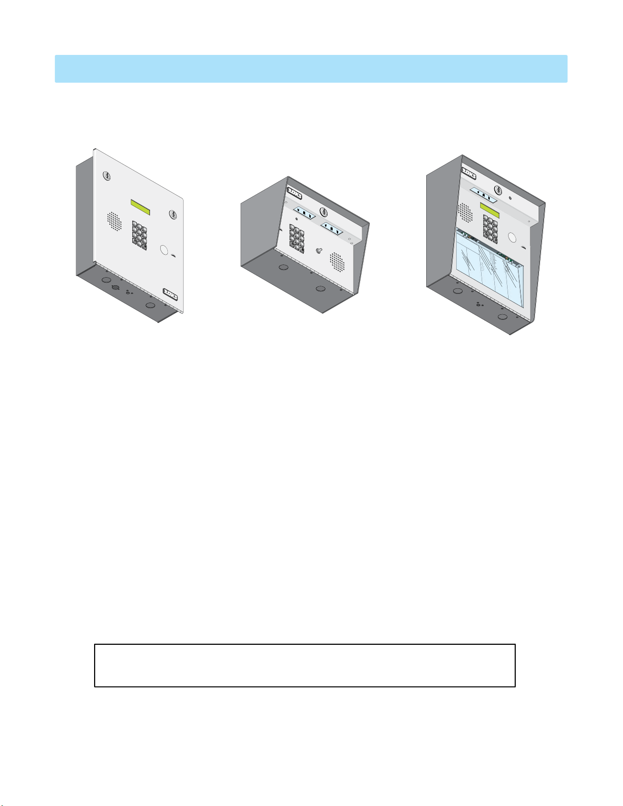
Flush Mount
SPECIFICATIONS
1803 / 1808 / 1810 Telephone Entry Systems, Circuit Board 1862-010 REV O or Higher.
TELEPHONE ENTRY SYSTEM
1
1803
2
3
4
5
7
6
8
9
0
OPER
1.
L
ocat
2.
AT
Press
e
Code
ING INSTRUCTIONS
Press “#”
Code
Nu
3.
m
E
Nu
nter
b
er on Di
m
to
b
o
er
n Tone.
Ha
.
If
n
recto
g UP.
Li
ne
ry
i
.
T
s Bu
r
y
Aga
s
y
,
in.
Surface Mount
1
2
3
4
5
7
6
Push Button
8
9
To
0
Call
1808
1
.
Lo
Ope
ca
2
.
t
e
Pr
Code
ra
t
ess Code
t
ing
N
o Ha
um
3.
In
ng-
be
N
En
s
r
um
O
U
tr
t
p.
e
n D
u
be
r
Tr
NA
O
ct
r
i
. I
n “
y
M
r
io
ec
Ag
E
f
L
OP
t
n
or
A
i
ai
ne
d
s
EN”
a
y
n.
m
I
s
s
J
Di
A
Bu
k
i
ns
spl
sy
M
a
,
Anne
y
P
r
or
e
s
e
ss
T
J
N
A
C
on
A
An
n
O
M
de
DE
E
e
r
s
y B
.
o
n
D
Ap
o
H
u
p
r
0
NA
la
l
t
0
e
t
nd
9
g
M
on
a
t
E
T
Do
Au
e
B
s
w
1
B
t
1
n
i
y
n
5
w
e
D
r
a
s
Du
r
B
M
a
l
b
35
s
C
r
b
e
a
2
a
u
r
u
di
i
l
gh
Du
B
l
l
o
a
B
s
k
5
P
C
s
e
5
a
s
J
1
r
D
n
e
En
B
y
e
g
j
P
65
a
Co
ha
r
COD
6
I
r
ll
d
i
n
El
B
E
s
e
li
G
r
s
0
l
C
i
78
n
W
o
l
J
8
y
07
e
F
B
r
a
e
R
r
r
22
a
n
Co
g
a
o
1
r
r
5
d
d
0
u
F
E
B
3
a
l
i
a
l
r
l
3
r
i
D
Co
ngs
ow
21
u
5
r
0
L
t
F
B
1
e
E
ro
r
24
na
k
Cr
e
9
r
a
4
T
i
n
0
Ga
B
s
4
r
G
o
r
47
f
s
D
i
e
e
a
6
l
S
4
t
o
6
B
n
1
r
B
o
0
w
D
03
a
n
n
2
J
i
49
e
B
l
s
r
ow
112
R
D
a
n
w
77
K
l
s
B
2
r
J
y
2
a
De
9
nt
2
La
63
W
By
h
3
a
e
r
8
on
D
2
M
i
2
l
R
l
4
P
8
B
1
y
a
49
Di
n
G
1
l
l
10
on
4
M
324
D
i
x
32
o
n
2
D
2
D
3
o
1
m
0
6
i
H
ni
8
c
33
k
D
P
on
2
88
i
c
H
8
k
P
1
D
17
on
51
n
e
8
r
K
Don
35
t
e
8
r
F
1810
467
76
5
9
5
4
992
Surface Mount
1
2
3
4
5
7
6
8
9
0
d
L
M
L
F
M
n
de
z
S
l
d
S
i
t
c
h
J
i
t
c
h
F
H
o
d
g
e
s
H
o
o
v
e
r
J
e
n
s
e
n
J
ohn
s
J
o
h
n
J
one
J
o
n
e
C
O
D
E
0
8
1
1
48
S
ee
1
8
le
M
8
8
6
y
7
a
3
n
J
3
c
S
8
i
n
e
l
i
2
06
l
e
G
M
32
c
3
a
k
4
s
H
76
t
Sh
i
n
D
3
a
8
e
M
33
8
r
3
a
R
10
s
A
t
Sh
o
1
n
a
8
55
F
n
M
3
k
5
1
oz
06
D
H
i
Si
n
9
a
m
3
7
J
M
02
o
31
n
uc
s
24
D
e
L
Smit
7
r
a
0
4
J
M
6
3
h
4
on
M
s
o
n
T
s
A
s
G
5
u
J
1
l
i
22
n
S
o
B
0
m
0
Nabor
0
55
a
5
c
04
h
St
H
0
K
e
49
08
e
N
l
e
0
a
2
bur
F
64
S
0
t
J
o
3
6
l
N
41
l
5
a
e
0
c
u
h
4
m
H
4
Sy
7
a
nn
n
8
791
f
Ni
7
o
9
J
l
x
A
00
on
T
6
o
R
m
55
0
Pa
2
l
i
7
n
1
t
s
7
t
e
o
4
T
r
n
5
o
s
on
m
L
0
0
Pe
32
7
p
6
F
s
r
o
5
e
n
46
z
T
F
om
A
41
1
Pe
0
ps
9
0
t
o
501
r
o
n
Ty
l
l
S
i
l
e
3
A
Ra
r
34
Q
y
3
30
J
W
a
2
s
13
h
i
n
21
g
W
t
1
on
a
2
s
G
29
h
i
n
5
gt
4
W
3
o
e
n
0
nt
K
0
7
L
9
87
W
h
1
i
t
34
i
ng
35
M
W
2
i
ns
6
09
t
on
W
F
y
38
a
t
t
9
J
67
9
21
1
670
4
41
Features
• Provides service for up to 600 residents but can be reprogrammed to provide service for up to 1000 residents.
• System can be programmed from the front keypad.
• System can be programmed remotely using a touch-tone telephone.
• System keypad will emit DTMF tones after a call is answered allowing the system to be used with auto-attendants,
answering machines, etc.
• Directory codes can be set from 1 to 4 digits in length and can be randomly assigned.
• Up to 16-digit phone number dialing with optional pauses between digits when necessary.
• Two internal relays allow the system to control a main entry point plus an additional entry point.
• Built in time clock provides hold open time zones, entry code time zones and “Flash” entry codes.
• 5-digit entry codes available for special needs.
• 2 programmable switch inputs can be set to activate a relay or dial a preprogrammed phone number.
Included with the system is an extra random keyed cabinet lock. If desired, for added security against
unauthorized entry into the system, the standard lock may be replaced with the random lock.
Note: DoorKing cannot replace this specific lock or keys if lost.
DoorKing, Inc. reserves the right to make changes in the products described in this manual without notice and without obligation of DoorKing, Inc. to notify any persons
of any such revisions or changes. Additionally, DoorKing, Inc. makes no representations or warranties with respect to this manual. This manual is copyrighted, all rights
reserved. No portion of this manual may be copied, reproduced, translated, or reduced to any electronic medium without prior written consent from DoorKing, Inc.
4
1800-060 Issued 7-19
Version A

TABLE OF CONTENTS
Important Notices FCC - United States, DOC - Canada
Glossary
General Information Installation Guidelines and Safety Information
SECTION 1 - INSTALLATION
1.1 General Installation
1.1.1 Remove Components from Enclosure
1.2.1 Install Enclosure for 1803 & 1810
1.2 1803 & 1810 Surface Mount Dimensions
1.2.1 Surface Mount Recess Kit Installation for 1803 & 1810
1.3 1803 & 1810 Flush Mount Dimensions
1.3.1 Flush Mount Kit Installation for 1803 & 1810
1.3.2 Self-Standing Lighted Kiosk for 1803 & 1810
1.3.3 Flush Mount Surface Mounting Kit Installation for 1803 & 1810
1.4 1808 Dimensions and Installation
1.5 Memory Chip Replacement
1.6 Postal Lock Installation
1.7 UL 294 Compliant Tamper Switch
SECTION 2 - WIRING
2.1 Wiring Guidelines
2.1.1 Power
2.1.2 Wire Runs
2.1.3 Grounding
2.1.4 Surge Suppression
2.1.5 Ferrite Filter
2.2 Terminal Descriptions
2.3 Telephone Entry System Wiring and Adjustments
2.3.1 Speaker Volume, Microphone and Feedback
2.3.2 Click Sensitivity - Use for Rotary-Dial Phones ONLY
2.3.3 LCD Display Contrast for 1803 & 1810
2.3.4 Master Code Switch
2.3.5 Ring Pin Jumper
2.3.6 Hands Free - Hand Set Jumper
SECTION 3 - PROGRAMMING
3.1 General Programming
3.1.1 Master Code
Overview for System Programming
3.1.2 Single or Multiple Systems
3.1.3 Relay Strike Time
3.1.4 “Tone Open” Sound ON or OFF
3.1.5 Talk Time
3.1.6 Tone Open Numbers
3.1.7 Programming Switch Input 1 and Switch Input 2
3.1.8 Number of Rings Before Telephone Entry System will Answer
3.1.9 PBX Line Access Code Programming
3.1.10 Star Key Function
3.1.11 Keypad Function (DTMF Tone Programming)
3.1.12 System to Stay On-Line or Hang-Up after Touch Tone Number Pressed
3.1.13 Automatic Hang-Up Function
3
3
4
5
5
6
7
8
9
10
11
12
13
14
15
16
17
18
18
18
19
19
19
19
20
21
22
22
22
23
23
23
24
24
24
25
26
26
26
26
27
27
27
28
28
28
28
29
1800-060 Issued 7-19
Version A
Table of Contents continued on next page
1

TABLE OF CONTENTS
SECTION 3 - PROGRAMMING Continued
3.2 Phone Number Programming
3.2.1 Programming the Directory Code Length
3.2.2 # Key - Insert an Amount of “Pause Time” Between Phone Number Digits
3.2.3 Programming Phone Numbers - Up to 16-Digits
3.2.4 Deleting Individual Phone Number
3.2.5 Deleting ALL Phone Numbers
3.2.6 Display / Delete Phone Numbers with UNKNOWN Directory Codes
3.2.7 Display Phone Numbers with KNOWN Directory Codes
3.2.9 16-Digit Phone Number Capability
3.2.10 Programming 7-Digit Phone Numbers
NOT used for Factory Set 16-Digit
3.2.11 Programming Area Codes (Area Code Reference Numbers)
Phone Number Programming
3.2.12 Programming Area Codes WITH Area Code Reference Numbers
3.2.13 Deleting Individual 7-Digit Phone Number
3.3 Entry Code Programming
3.3.1 Programming Four-Digit Entry Code
3.3.2 Delete Individual Four-Digit Entry Code
3.3.3 Delete ALL Four-Digit Entry Codes
3.3.4 Four-Digit Entry Code Divide Number to Activate Relays
3.3.5 Four-Digit Entry Code (Reverse Relay Activation ONLY)
3.3.6 Programming Five-Digit Entry Code
3.3.7 Delete Individual Five-Digit Entry Code
3.3.8 Delete ALL Five-Digit Entry Codes
3.3.9 Five-Digit Entry Code Divide Number to Activate Relays
3.4 Time Functions Programming
3.4.1 Programming Time Clock
3.4.2 Automatic Relay Activation Time Zones
3.4.3 Four-Digit Entry Codes Time Zone
3.4.4 Five-Digit Entry Codes Time Zone
3.4.5 “Flash Entry Codes” Active for ONE-DAY ONLY
SECTION 4 - SYSTEM OPERATING INSTRUCTIONS
4.1 General Instructions
4.1.1 Guest Instructions
4.1.2 Responding to a Guest Call
4.1.3 Using an Entry Code
4.2 System Administrator
4.2.1 Remote Programming (Touch-Tone Phone)
4.2.2 Remote Relay Activation
4.2.3 Remote Relay Check
4.2.4 Remote Entry Code Time Zone Enable / Disable
4.2.5 Remote Automatic Relay Time Zone Enable / Disable
4.3 Miscellaneous Operating Instructions
4.3.1 Switch Input 1 & 2 Switch Operation
4.3.2 Talk Time
4.3.3 Phone Line Sharing for Multiple Telephone Entry Systems
4.3.4 Connection to a PBX
4.3.5 Areas with 10-Digit Dialing
SECTION 5 - MAINTENANCE
5.1 Replacement Parts
5.2 Troubleshooting
5.3 Accessories
Wiring Schematic
SECTION 6 - LOG TABLES
RESIDENT INSTRUCTIONS
3.2.8 7-Digit Phone Number Capability
- Limited Use -
7-Digit Phone #
30
30
30
31
31
32
32
32
33
33
34
34
35
35
36
36
36
36
36
37
37
37
37
37
38
38
38
39
40
40
41
41
41
41
41
42
42
42
42
43
43
44
44
44
44
44
44
45
45
45-46
47
47
48-49
50
2
1800-060 Issued 7-19
Version A

Important Notices
FCC – United States
This equipment has been tested and found to comply with the limits for a class A digital device, pursuant to Part 15 of the FCC Rules and
Regulations. These limits are designed to provide reasonable protection against harmful interference when the equipment is operated in a
commercial environment. This equipment generates, uses, and can radiate radio frequency energy and, if not installed and used in accordance
with the instruction manual, may cause harmful interference to radio communications. Operation of this equipment in a residential area is
likely to cause harmful interference in which case the user will be required to correct the interference at his own expense.
FCC Registration Number: DUF6VT-12874-OT-T
DOC - Canada
The Canadian Department of Communications label identifies certified equipment. This certification means that the equipment meets certain
telecommunications network protective, operational, and safety requirements. The Department does not guarantee the equipment will operate
to the users satisfaction.
Before installing this equipment, users should ensure that it is permissible to be connected to the facilities of the local telecommunications
company. The equipment must also be installed using an acceptable means of connection. The customer should be aware that compliance
with the above conditions may not prevent degradation of service in some situations.
Repairs to certified equipment should be made by an authorized Canadian maintenance facility designated by the supplier. Any repairs or
alterations made by the user to this equipment, or equipment malfunctions, may give the telecommunications company cause to request the
user to disconnect the equipment.
Users should ensure, for their own protection, that the electrical ground connections of the power utility, telephone lines, and internal metallic
water pipe system, if present, are connected together. This precaution may be particularly important in rural areas.
CAUTION: Users should not attempt to make such connections themselves, but should contact the appropriate electric inspection authority, or
electrician, as appropriate.
DOC Registration Number: 1736 4528 A
Notice:
The Load Number (LN) assigned to each terminal device denotes the percentage of the total load to be connected to a telephone loop which is
used by the device, to prevent overloading. The termination on a loop may consist of any combination of devices subject only to the requirement that the sum of the load numbers of all the devices does not exceed 100.
Notice:
DoorKing does not provide a power transformer on units sold outside of the United States. Use only transformers that are listed by a
recognized testing laboratory to power the telephone entry system. An Inherently Protected Transformer must be used to power this device.
The Telephone Entry systems require a 16.5-volt, 20 VA transformer.
Listing:
This product has been tested to and found to be in compliance with the UL 294 Safety Standard and Certified to CAN/ULC-S319-05 by Intertek
Testing Services NA Inc. (a Nationally Recognized Testing Laboratory) and is ETL listed.
Performance Levels
Destructive Attack: Level I
Line Security: Level I
Endurance: Level IV
Standby Power: Level I (Level II with 12 VDC, .7 Ah, SLA battery, required
Single Point Locking Device with Key Locks: Level I
for Canadian certification)
Glossary
ACCESS CONTROL SYSTEM: A collection of means, measures and specific practices that when combined, form or compose a systematic
approach, which enables an authority to control access to areas and resources in a given physical facility. An access control system, within
the field of physical security, is generally seen as the second layer in the security of a physical structure.
ALARM: A condition indicating a state of alert or tamper detection.
ALARM SIGNAL: A transmission of an alarm condition or alarm report.
CONTROLLED AREA: A room, office, building, facility, premises, or grounds to which access is monitored, limited, or controlled.
EQUIPMENT: Any part of an electronic access control system, such as access control units, reader interface modules, access point actuators,
access point sensors, keypads, and the like.
PROTECTED AREA: A room, office, building, facility, premise or grounds to which access is monitored, and limited and/or controlled,
whereby the authorized person of the Access Control System may grant access to non-authorized persons.
RESTRICTED AREA: A room, office, building, facility, premise or grounds to which access is monitored, and limited and strictly controlled,
whereby only the administrator of the Access Control System shall issue credentials that will lead to access.
1800-060 Issued 7-19
Version A
3
General Information
• Prior to beginning the installation of the telephone entry system, we suggest that you become familiar with the instructions, illustrations, and wiring
guidelines in this manual. This will help insure that you installation is performed in an efficient and professional manner.
• The proper installation of the telephone entry panel is an extremely important and integral part of the overall access control system. Check all local
building ordinances and building codes prior to installing this system. Be sure your installation is in compliance with local codes.
• When used to control a door or pedestrian gate, try to locate the telephone entry system as near as possible to the entry point. The unit should be
mounted on a rigid wall to prevent excessive shock and vibration from closing doors or gates. Continuous vibration and shock from slamming doors
or spring-loaded pedestrian gates will damage the circuit board.
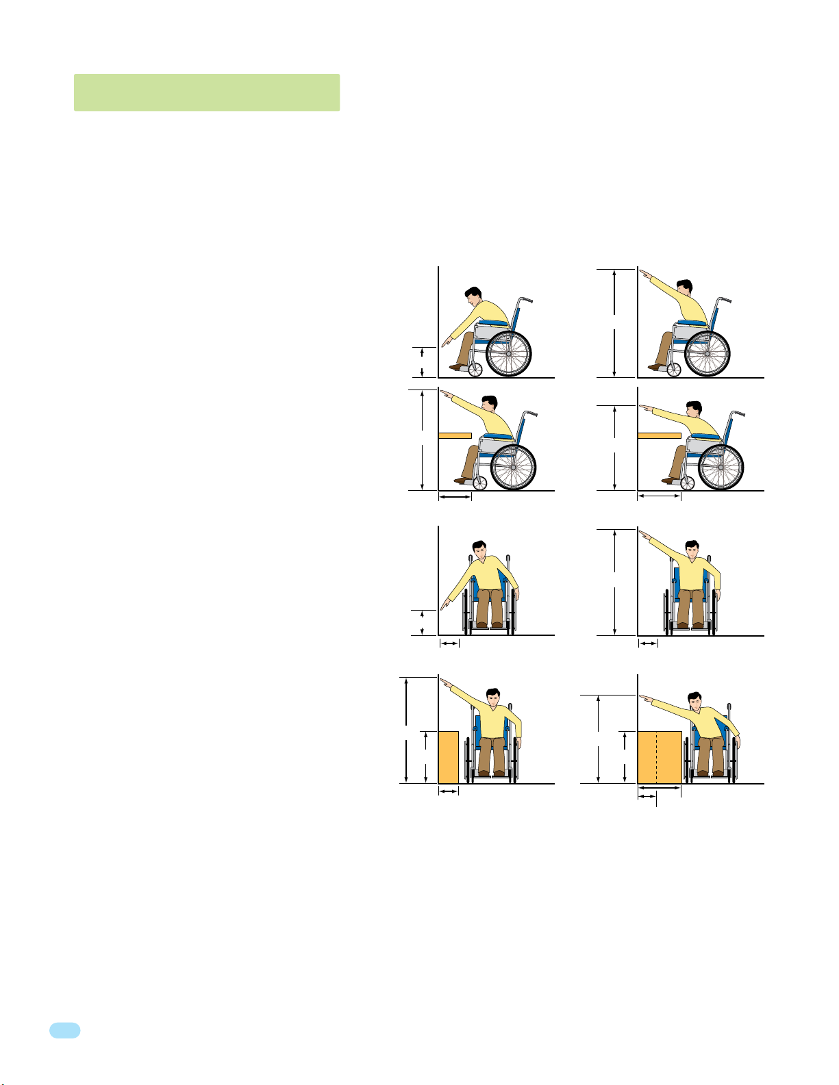
• ADA mounting requirements for door control (Ref: ICC/ANSI A117.1-2009). The requirements below apply ONLY when the telephone entry system is
being used to control entry through A PUBLIC DOOR ONLY. If this system is used to control entry through a vehicular gate or private entrance, the
dimensions noted below do not apply.
1. Unobstructed Forward Reach. Where a clear floor or
ground space allows only a forward approach to an object
and is unobstructed, mounting height shall be a minimum
of 15 inches (381 mm), and a maximum of
48 inches (1.22 m), above the floor or
ground to the operable controls.
2. OBSTRUCTED HIGH Forward Reach. If the high forward
reach is over an obstruction, reach and clearances shall
be as shown. NOTE: If the height of a control is 48"
maximum, then the length of the obstruction
must be 20" or less. If the height of a control
is 44" maximum, then the length of the
obstruction may be increased to 25" or less.
Under no circumstances should the unit be mounted directly to a moving door or gate.
Minimum
Height
Maximum
Height
15”
48”
Maximum
Maximum
Height
Height
48”
44”
48”
34”
25” or Less
Maximum Length of
10”
Clear Floor Space
Less than 24”
20” or Less
3. Unobstructed Side Reach. Where a clear floor or ground
space allows a parallel approach to an object and the side
reach is unobstructed, and the edge of the clear floor space
is 10 inches (255 mm) maximum from the object, mounting
height shall be a minimum of 15 inches (380 mm), and a
maximum of 48 inches (1.22 m), above the floor
or ground to the operable controls.
4. OBSTRUCTED HIGH Side Reach. If the side reach is over
an obstruction 10 inches or less, mounting height shall
be a maximum of 48 inches (1.21 m) above the floor or
ground to the operable controls. If the side reach
is over an obstruction greater than 10 inches,
but less than 24 inches, mounting height shall
be a maximum of 46 inches (1.17 m) above the
floor or ground to the operable controls.
• When used to control a vehicular gate with an automatic gate operator, the telephone entry system must be mounted a minimum of six (6) feet
away from the gate and gate operator, or in such a way that a person cannot operate the entry system and/or touch the gate or gate operator at
the same time.
• Be sure that the system is installed so that it is not directly in the traffic lane. Goose neck mounting post and kiosks work well for these type systems.
When planning where to locate the system, take into consideration traffic lane layouts, turn around lanes for rejected access, conduit runs, power
availability, etc.
• Environmental factors must also be taken into account. Surface mount units are designed for direct outdoor installations, however it is preferable to
protect them from direct exposure to driven rain or snow whenever possible. Flush mount units must be protected from direct exposure to the
elements.
• This telephone entry system contains a number of static sensitive components that can be damaged or destroyed by static discharges during
installation or use. Discharge any static prior to removing the circuit board from the lobby panel by touching a proper ground device.
• Instruct the end user to read and follow these instructions. Instruct the end user to never let children play with or operate any access control
device. This Owner’s Manual is the property of the end user and must be left with them when installation is complete.
Minimum
Height
Maximum
Height
48”
15”
34”
Maximum Length of
10”
Clear Floor Space
10” or Less
Maximum
Maximum
Height
Height
46”
Greater than 10”
4
1800-060 Issued 7-19
Version A
SECTION 1 - INSTALLATION
J
s
o
n
H
g
a
t
e
B
n
D
b
a
u
g
h
B
s
J
a
r
I
r
l
i
n
J
e
r
n
a
r
d
E
i
l
l
i
n
g
s
L
B
r
o
k
e
r
T
B
r
o
s
e
S
B
r
o
w
n
J
B
r
o
w
n
K
B
r
y
a
n
t
W
B
y
r
o
n
R
B
y
a
n
G
2
2
1
3
2
1
2
4
9
4
7
6
0
0
3
1
1
2
2
9
2
8
2
2
4
9
1
3
2
4
2
3
1
3
3
2
1
1
7
C
r
a
i
n
s
G
D
a
l
t
o
n
B
D
a
n
i
e
l
s
R
D
a
w
l
s
J
D
e
L
a
h
a
e
M
D
i
l
l
P
D
i
l
l
o
n
M
D
i
x
o
n
D
D
o
m
i
n
i
c
k
P
D
o
n
i
c
k
P
D
o
n
n
e
r
K
D
o
n
t
e
r
F
8
8
8
5
1
8
3
5
8
4
6
7
7
6
5
9
5
4
9
9
2
H
o
o
v
e
r
H
J
e
n
s
e
n
D
J
o
h
n
s
o
n
M
J
o
h
n
s
o
n
T
J
o
n
e
s
A
J
o
n
e
s
G
0
3
2
4
1
9
R
a
y
J
H
t
e
B
u
g
h
B
I
J
a
r
d
E
i
n
g
s
L
k
e
r
T
o
s
e
S
r
o
w
n
J
r
o
w
n
K
B
r
y
a
n
t
W
B
y
r
o
n
R
B
y
a
n
G
2
1
3
2
1
2
4
9
4
7
6
0
3
1
2
9
2
2
2
4
9
1
2
4
3
1
3
3
2
1
7
r
a
i
n
s
G
a
l
t
o
n
B
a
n
i
e
l
s
R
a
w
l
s
J
e
L
a
h
a
e
M
i
l
l
P
i
l
l
o
n
M
i
x
o
n
D
o
m
i
n
i
c
k
P
o
n
i
c
k
P
o
n
n
e
r
K
o
n
t
e
r
F
8
8
185
8
6
7
6
5
5
4
9
2
o
o
v
e
r
H
J
e
n
s
e
n
D
J
o
h
n
s
o
n
M
J
o
h
n
s
o
n
T
J
o
n
e
s
A
J
o
n
e
s
G
0
3
2
4
1
9
R
a
y
J
N
A
M
E
D
o
r
l
a
n
d
T
D
o
w
n
w
a
r
d
L
2
9
0
1
5
2
0
2
8
0
7
2
8
2
8
3
4
2
C
O
D
E
N
A
M
E
J
o
r
d
a
n
M
J
o
r
d
e
n
L
J
o
r
g
e
n
s
e
n
B
K
l
e
i
n
D
K
n
o
b
l
i
c
h
B
L
a
m
b
B
L
a
n
d
D
L
a
n
d
e
r
s
S
0
2
3
5
6
2
6
4
7
7
3
6
4
0
8
8
0
3
0
2
6
9
9
6
3
3
8
4
7
6
1
0
1
0
6
9
C
O
D
E
N
A
M
E
R
e
e
s
e
D
R
e
i
g
e
r
B
R
e
m
i
n
g
t
o
n
S
R
e
s
s
e
g
i
e
u
R
R
o
l
l
i
n
s
A
S
c
h
u
s
t
e
r
S
S
e
e
l
e
y
J
S
e
l
l
e
c
k
H
S
h
a
e
r
R
S
h
a
n
k
D
S
i
mo
n
s
L
S
m
i
t
h
J
S
o
m
a
c
h
H
0
8
1
1
4
8
8
8
7
0
6
3
8
8
3
5
5
1
7
3
1
4
3
5
0
5
5
0
8
2
6
5
0
7
9
1
0
2
1
0
7
6
1
0
0
3
3
4
2
1
3
C
O
D
E
A
M
E
o
r
l
a
n
d
T
o
w
n
w
a
r
d
L
2
9
0
5
2
0
2
8
0
7
2
2
8
3
4
2
O
D
E
A
M
E
J
o
r
d
a
n
M
J
o
r
d
e
n
L
J
o
r
g
e
n
s
e
n
B
l
e
i
n
D
n
o
b
l
i
c
h
B
a
m
b
B
a
n
d
D
a
n
d
e
r
s
S
0
2
3
5
6
2
6
4
7
7
3
6
4
0
8
8
0
3
0
2
6
9
9
6
3
8
4
7
6
0
1
6
9
O
D
E
A
M
E
e
e
s
e
D
R
e
i
g
e
r
B
R
e
m
i
n
g
t
o
n
S
R
e
s
s
e
g
i
e
u
R
o
l
l
i
n
s
A
c
h
u
s
t
e
r
S
S
e
e
l
e
y
J
e
l
l
e
c
k
H
h
a
e
r
R
h
a
n
k
D
i
mo
n
s
L
m
i
t
h
J
o
m
a
c
h
H
0
8
1
4
8
8
8
7
0
6
3
8
3
5
5
1
7
3
1
4
3
5
5
5
8
2
5
0
9
1
2
1
7
6
0
0
3
3
4
2
1
3
O
D
E
Prior to installing the telephone entry system, we suggest that you become familiar with the instructions, illustrations, and
wiring guidelines in this manual. This will help insure that you installation is performed in an efficient and professional manner.
Order your telephone line to be installed at least two weeks prior to the planned telephone entry system installation date.
This will assure that a phone line is available when the unit is installed. The telephone company will require the following
information from you:
Type: Touch Tone, Loop Start
Ringer Equivalence: 0.0 A
Jack Type: RJ11C
FCC Registration (US): DUF6VT-12874-OT-T
DOC (Canada): 1736 4528 A
Caller ID: You may want to order caller ID blocking from the telephone company for the entry system phone line. Without
caller ID blocking, residents with the proper phone equipment WILL BE ABLE to identify the telephone number that the
telephone entry system is installed on. This may or MAY NOT be desirable.
Call Waiting: Residents may order call waiting from their local telephone company AFTER the system has been installed.
They can avoid missing calls coming from the telephone entry system while they are using their phone (No busy signal).
1.1 General Installation
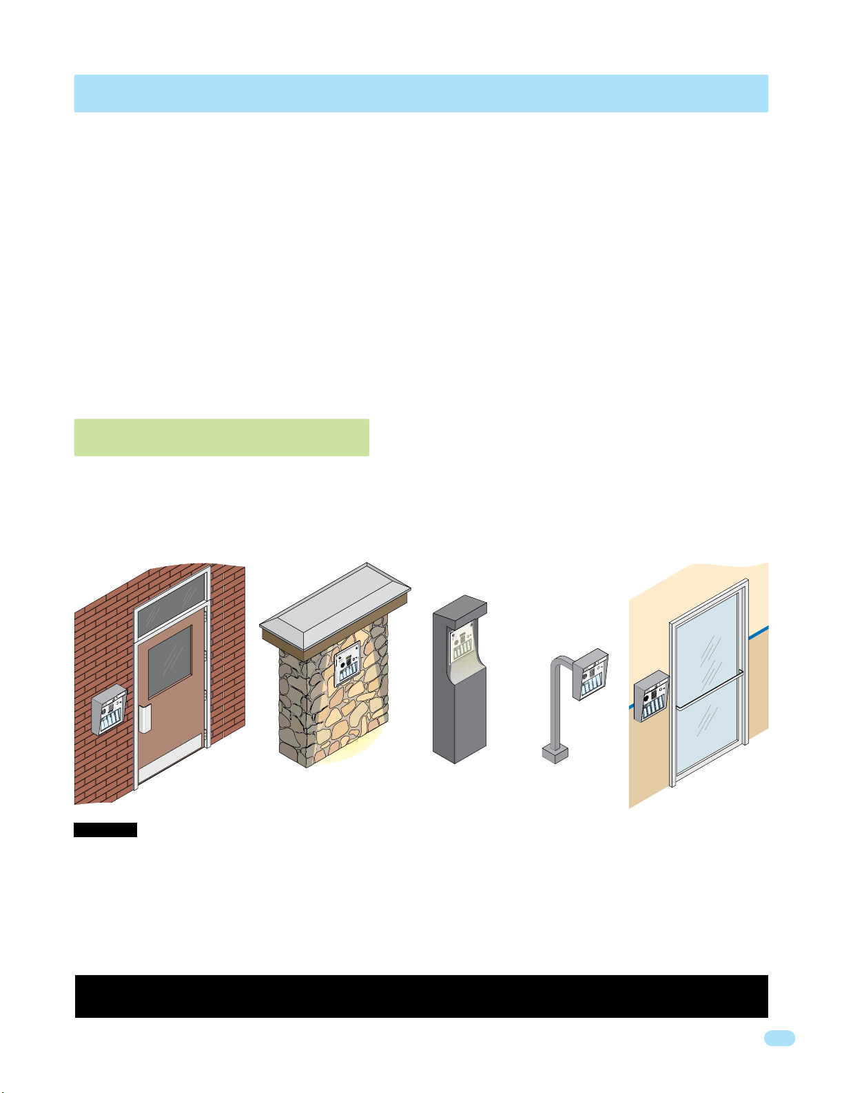
There are 2 different styles of the telephone entry systems (Surface mounts and Flush mounts-1803/1810 only), and different ways to mount
them (On a wall, in a wall, attached to a architectural style post, kiosk, etc). Models will ALL need a telephone line, power and communication
wires run to them in conduit or inside a architectural style post. Feed all of the wires through the back or bottom of the entry system using the
existing knock-outs provided in the enclosures. DO NOT make any new holes in the enclosure to feed wires through. Keep ALL the entry
system’s wires away from any existing high voltage power wires a minimum of 6” to help prevent any noise and hum pickup in the system’s
phone line. The system MUST also be properly grounded to function correctly.
Outside Wall
Kiosk
DoorKing Self-Standing
Lighted Kiosk, 1803 and
1810 Flush Mounts Only
DoorKing
Mounting Post
Surface Mount Only
Inside WallLighted-Covered
WARNING If this telephone entry system is used to control a vehicular gate with an automatic gate operator, the telephone entry
system must be mounted a minimum of six (6) feet away from the gate and gate operator, or in such a way that the user cannot come into
contact with the gate or gate operator when using this entry system.
The telephone entry system contains static sensitive components that can be damaged or destroyed by static discharges during installation.
Discharge any static prior to removing the circuit board by touching a proper ground device. GREAT care must be taken after removing the
components from the enclosure to protect them throughout the installation. Carelessness on your part is NOT covered under warranty.
Make sure ALL dirt, metal or wood debris is removed from inside the enclosure after mounting it. A through cleaning of the enclosure is
needed before re-installing the components back into the system and wiring it. Any debris left inside could damage the control board and
cause the telephone entry system to malfunction during operation.
Included with the system is an extra random keyed cabinet lock. If desired, for added security against unauthorized entry into the system,
the standard lock may be replaced with the random lock. Note: DoorKing cannot replace this specific lock or keys if lost.
1800-060 Issued 7-19
Version A
5
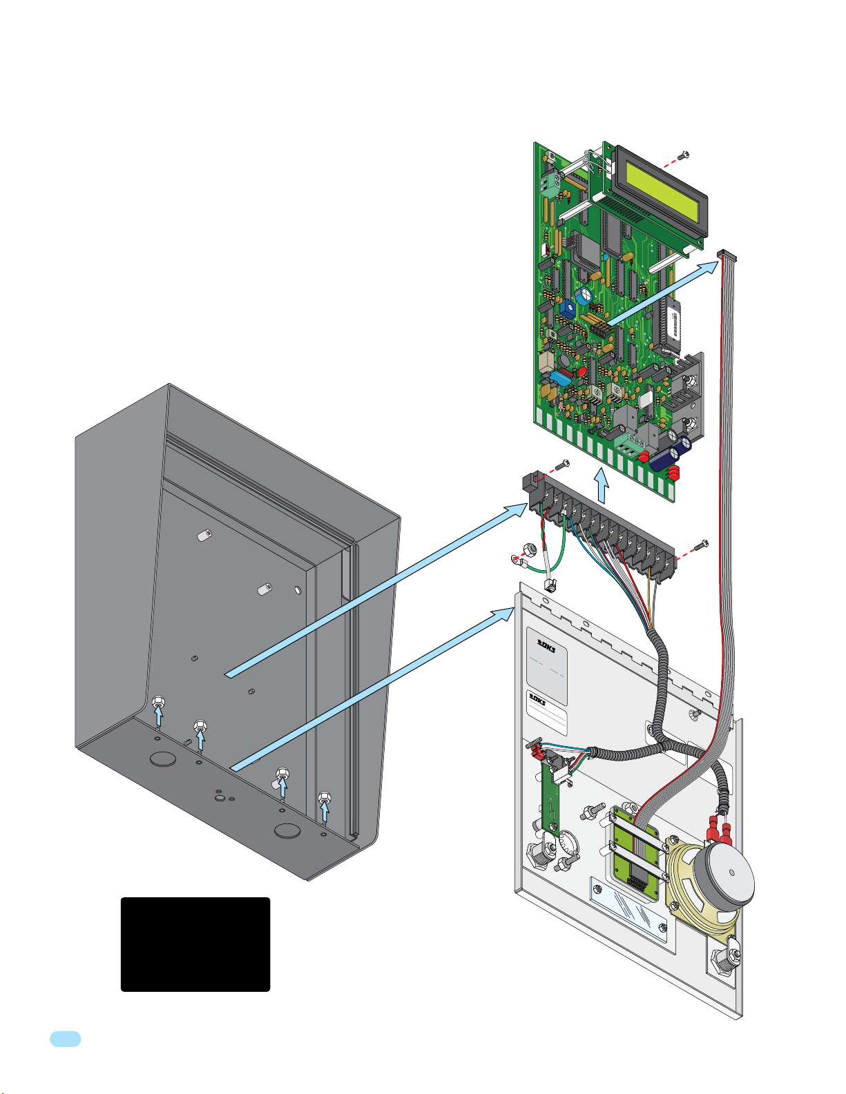
1.1.1 Remove Components from Enclosure
There are 2 different styles of telephone entry systems - Surface mounts and Flush
mount. The basic component removal is the same for all models, 1803 surface
mount is shown as an example.
1. Disconnect the keypad ribbon cable from the circuit board.
2. Remove the screw from the top of the circuit board.
CONTRAST
DOORK
ING 186
2-010
Ci
rcuit Board
Screw
3. GENTLY remove the circuit board by pulling it out of the main terminal.
4. Remove the two screws from the main terminal and remove the
ground wire locknut.
5. Remove the locknuts from the faceplate hinge.
6. Remove the faceplate, main terminal (still wired), store them in a
Safe Place until they need to be re-installed.
7. Proceed to section 1.2.1 for 1803 & 1810 models. Go to section 1.4 for
1808 model.
1803
Surface
Mount
Enclosure
ON
M
AST
C
E
O
R
DE
OFF
MIC VOL
Main Terminal Screw
RING
P
HONE
Ground
Wire
Ribbon
Cable
CLCK
SENSE
KEYPAD
FEE
SPK
VOL
TO
N
E
O
FF
H
F
H
S
PSW
MICMICG
DBA
CK
NO
N
CC
Main Terminal
R
COMSPK
T
ONE
ON
CGND
sn XX
0000010100010
1810-075
THIS SIDE UP
CBAT
NC
NO
16AC
16AC
Faceplate
Hinge
Locknuts
Discharge any static
BEFORE removing
the circuit board by
touching a proper
ground device.
Mf
g. i
n
U.
S
D
.
A
O
O
.
Acce
R
K
T
ss
h
I
i
N
s p
C
G
o
®
o
r
n
r
o
,
t
S
m
du
r
o
i
I
n
o
l
ct
NC
So
ce
r
e
i
s
o
19
Pa
l
u
.
f t
m
t
4
t
i
h
a
en
o
8
e
n
n
u
t No
s
fo
f
a
l
l
ct
o
.
wi
u
r
D
e
n
d
a
g
t
u
e
U
nd
.
S
e
.
r o
P
a
n
t
e
e
n
P
t
a
s.
t
en
t No
.
D
a
t
e
O
T
H
E
R
P
AT
D
O
E
OR
NT
S
K
I
P
N
E
G
N
IN
DIN
C
.
G
,
I
N
G
LE
WO
OD
CA
DO
O
PA
R
R
K
T
I
NUM
N
G
®
B
ER
,
M
I
NC
A
D
E
I
.
N
U
S
A
R
EV
S
ER
IA
L
N
O.
Faceplate
AC
C
ES
S
S
YS
C
ONTRO
TEM
O
C
U
ONFORM
UNI
T
D
D
L
O
O
O
O
TS
R
R
KI
I
U
ngl
S
N
S
E
G
e
w
/
TO
M
W
ood,
od
E
UL
T
e
Se
l
C
# 1800
a
S
ri
al
9
TD 2
Co
0301
#
m
Se
94
pl
F
.
ri
i
C.
e
e
s
s
C.
F
D
.C.
R
U
e
C.
F
g
6V
i
R
s
Part
t
i
T
ra
nge
-12874t
i
68
on
J
r
a
Equi
ck
#
U
O
v.
SO
T
-T
0.0A
C
R
J
11C
or
W
6
1800-060 Issued 7-19
Version A
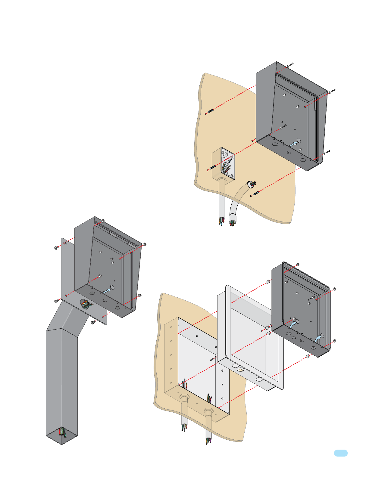
1.1.2 Install Enclosure for 1803 & 1810
There are 2 different styles for the 1803 & 1810 - surface and
flush mount. The illustrations below show typical installations
but specific installations can vary from this.
1. Mount the enclosure using the mounting holes provided
in the corners (see sections 1.2 and 1.3 for your chosen
model dimensions including kit installations). Be sure that
mounting screws (Not supplied) do not protrude into the
enclosure where they could cause a short on the back of the
circuit board. Make any necessary conduit connections
through the back or bottom of the enclosure using the
existing conduit knock-outs. DO NOT make any new conduit
holes in the enclosure.
2. Route all wiring through conduit or architectural post
(not supplied) into enclosure.
3. Clean out the enclosure. Make sure that all dirt, metal
and/or wood debris is removed.
4. Re-install components back into the enclosure (Reverse
section 1.1.1 steps on previous page). Use the wiring
schematics in the back of this manual to help re-install the
components if necessary. DO NOT apply any power at this
time.
Mount ON a Surface
(See sections 1.2).
Wall
Use appropriate
hardware to secure
enclosure to the wall
(not supplied).
Mounting
Su
rface Mount
Enclosur
H
e
Knock-o
o
le
ut
Mount to an
Architectural
Mounting
Post
Mounting H
o
rface Mount
Enclosure
Knock-o
le
ut
Su
Use hardware supplied with
architectural post to secure
enclosure to post.
Note: An architectural
mounting post anchored
in concrete does not
make a good ground.
Conduit run
to junction box
Examples of conduit runs that may be used, depending on how you choose to run the wiring.
Some installations will allow the conduit to be run outside the wall and connect to the bottom
of the enclosure but this is generally NOT recommended.
Mount IN a Surface
(See sections 1.2.1 and 1.3.1 and 1.3.2).
Wall
Mounting
(Not s
Screws
upplied)
Rough-In
Box
Conduit
sweep run
Plastic Spacer
T
rim
Ring
Locknut
Flush Mount
Enclosure
Knock-out
s
1800-060 Issued 7-19
Version A
Run all wires
inside post.
7
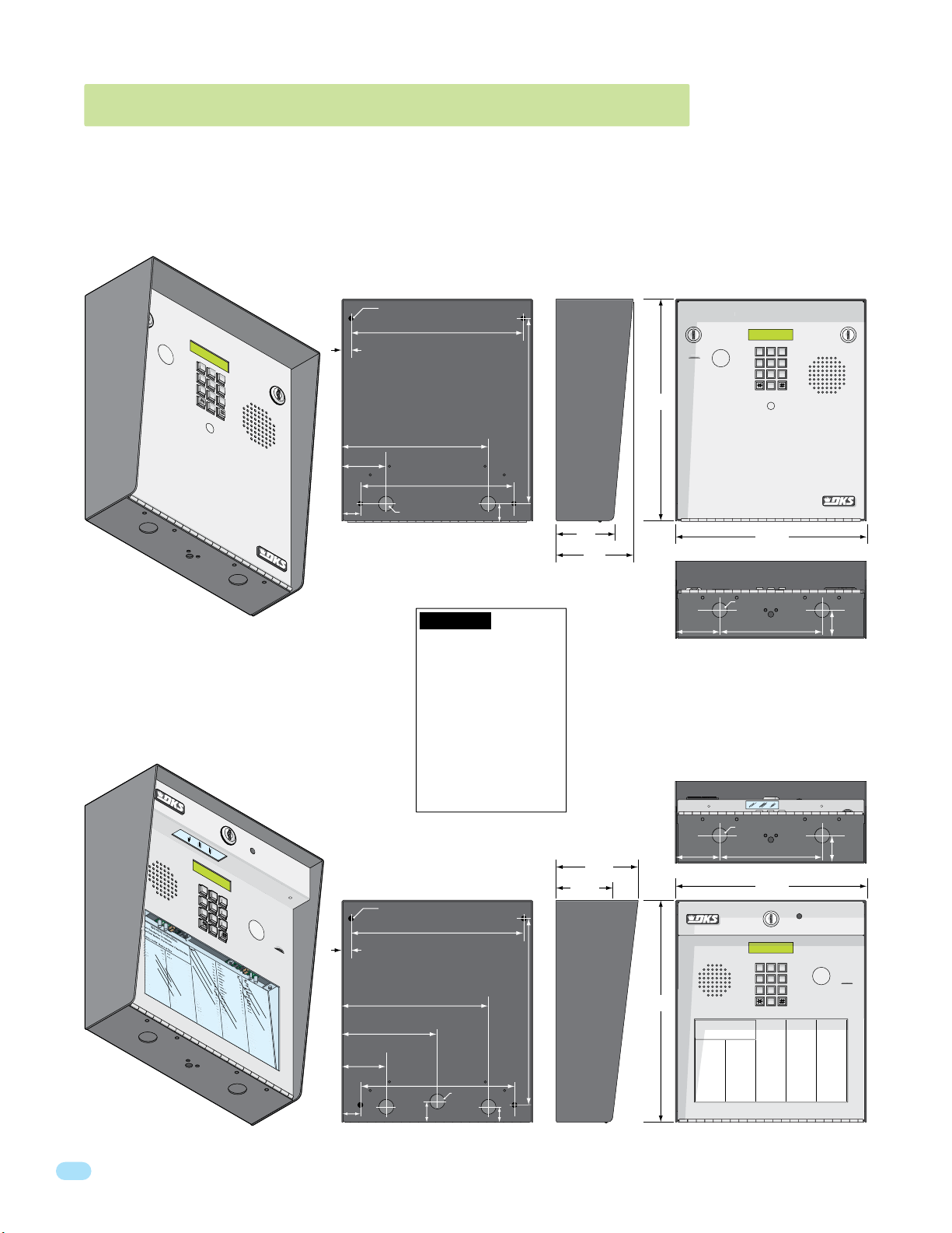
7
8
9
4
5
6
1
2
3
0
1.2 1803 & 1810 Surface Mount Dimensions
7
8
9
4
5
6
1
2
3
0
H
a
n
g-Up.
Tr
y Again.
b
a
ug
h
B
s
J
a
r
I
rli
n
J
rn
a
r
d
E
lli
n
gs
L
r
o
k
e
r
T
Br
o
s
e
S
Br
o
w
n
J
Bro
w
n
K
Br
y
a
nt
W
By
ro
n
R
By
a
n
G
5
5
1
6
5
6
0
7
8
2
2
1
32
1
2
4
9
4
7
6
0
0
3
11
2
2
9
2
8
2
2
4
9
1
3
2
4
23
1
3
3
2
1
1
7
Ca
r
d
i
l
l
o
P
Ca
r
n
e
y
P
Coll
in
s
G
Co
l
y
e
r
R
Co
r
d
u
la
D
Co
ur
t
E
Cr
a
i
n
s
G
Da
lt
o
n
B
Da
n
i
e
l
s
R
Da
wls
J
De
L
a
h
a
e
M
Di
ll P
Di
llo
n
M
Di
x
on
D
Dom
i
n
i
c
k
P
Doni
c
k
P
Donn
e
r
K
Dont
e
r
F
8
0
7
5
0
3
5
0
1
4
0
4
46
1
24
9
7
7
2
63
3
48
1
1
0
4
32
2
06888
8
51
8
35
8
4
6
7
76
5
95
4
99
2
C
O
DE
D
or
l
a
nd
T
D
o
wnwar
d
L
D
ub
r
e
u
i
l
M
D
uk
e
s
D
E
n
g
h
a
rd
L
E
l
lis
W
F
a
ra
go
F
F
a
r
r
o
w
M
F
e
rna
n
de
z
S
G
a
rf
i
e
l
d
S
G
a
r
re
a
u
J
G
e
nt
r
y
M
G
onza
le
z
H
H
a
be
rfe
l
d
A
H
a
mm
e
r
V
H
e
nd
r
ix
K
H
i
r
d
A
H
i
tch
J
J
o
h
n
s
o
n
M
J
o
hn
s
o
n
T
J
o
ne
s
A
J
one
s
G
0
0
5
4
9
0
34
1
8
7
9
5
5
7
0
3
2
4
1
9
C
O
D
E
M
u
lin
B
N
a
b
o
r
K
N
a
b
u
r
J
N
e
u
m
a
n
n
J
N
ix
o
n
R
P
a
t
t
e
r
s
o
n
F
P
e
r
e
z
F
P
e
t
r
o
lli
A
R
a
y
J
1
2
2
0
4
0
6
4
0
4
4
7
0
0
6
7
4
5
5
4
6
5
0
1
3
3
0
2
1
1
5
4
3
98
7
3
5
2
S
m
it
h
J
S
o
m
a
c
h
H
S
t
e
e
le
F
S
t
o
lla
c
h
H
S
y
n
f
o
l
A
T
o
m
lin
s
o
n
L
T
o
m
p
s
o
n
A
T
o
m
p
s
o
n
S
Ty
le
r
Q
W
a
s
h
i
n
g
t
o
n
G
W
a
s
hi
n
g
t
o
n
K
We
n
t
L
W
h
i
t
ing
M
W
in
s
t
o
n
F
W
y
a
t
t
J
0
8
1
1
4
8
8
8
7
0
6
3
8
8
3
5
5
1
7
3
1
4
35
0
5
5
0
8
2
6
5
0
7
9
1
0
2
1
0
7
6
1
0
0
3
3
4
2
1
3
2
2
9
0
0
7
1
3
4
60
9
3
8
9
6
7
9
2
1
1
6
7
0
4
4
1
C
O
D
E
9
6
3
0
9
6
3
0
Surface mount units can be mounted directly to a wall, pilaster, post mounted using a DoorKing architectural style mounting
post (P/N 1200-037 and 1200-038) or recessed in a wall (see next page) with the surface mount recess kit (P/N 1803-150). Be
sure the unit is mounted securely and is not subject to vibration from closing doors or gates.
Side ViewBack View Front View
1
2
3
NA
1803
to
H
a
n
g-Up.
Tr
M
y Again.
E
Ba
ls
Ca
b
a
r
ug
d
i
l
Ba
l
h
o
B
s
5
P
Ca
s
5
J
1
r
n
e
Be
y
P
ja
6
Coll
5
r
I
6
in
Be
s
G
rli
0
Co
7
n
8
l
J
y
e
Be
r
R
rn
2
Co
2
a
1
r
r
d
d
E
u
Bi
la
lli
32
D
Co
n
gs
1
ur
L
t
Bro
E
2
Cr
k
4
e
9
a
r
i
n
T
s
Br
G
o
4
Da
s
7
e
6
lt
S
o
n
Br
B
o
0
Da
w
0
3
n
n
J
i
e
Bro
l
s
11
Da
w
2
n
wls
K
Br
J
y
2
De
a
9
nt
2
L
W
a
h
By
a
ro
8
Di
2
n
2
ll P
R
By
a
4
Di
n
9
G
1
llo
n
3
Di
2
4
x
on
23
Dom
1
3
Doni
3
2
1
Donn
1
7
Dont
1810
T
ELEPHONE ENTRY
OP
1.
L
E
oca
RAT
2.
te
Press C
Cod
P
ress
o
3.
E
“#
nt
e
r
on
D
or
l
a
nd
D
o
wnwar
D
ub
r
D
uk
e
E
n
g
C
O
DE
E
l
lis
8
0
F
7
a
ra
5
0
F
3
a
r
5
0
F
1
e
4
0
G
4
46
G
1
24
G
9
R
7
7
2
63
3
e
M
48
1
1
0
4
M
32
2
D
06
i
8
n
i
c
k
P
88
c
8
k
P
51
8
e
r
K
35
e
8
r
F
4
6
7
76
5
95
4
99
2
.25” Dia. Mounting Hole
10.125”
SYST
E
M
1
2
3
4
5
6
7
8
9
0
.5”
13”
10.875”
8.625”
2.625”
IN
G
e
Nu
INSTRUCTIONS
de
mb
N
er
umber
”
to
on
H
D
. If
To
a
irecto
ng
n
L
e
UP
in
.
e
ry
.
is
.
Try
Busy
Agai
,
n
.
1.125”
.875” Dia
9”
1”
3”
MODEL 1803
WARNING! If this entry
system is used to control a
4.5”
2.625”
vehicular gate with an
automatic gate operator, the
entry system must be
mounted a minimum of six
(6) feet away from the gate
and gate operator, or in
such a way that a person
cannot operate the entry
system and touch the gate
or gate operator at the same
time.
2.625”
4.75”
1
2
3
4
5
7
6
8
9
0
T
d
L
e
u
i
l
C
M
O
D
E
s
D
h
a
rd
L
W
go
F
r
o
w
M
rna
n
de
z
a
S
rf
i
e
l
d
S
a
r
re
a
u
J
e
nt
r
y
M
G
onza
le
z
H
H
a
be
rfe
l
d
H
a
A
mm
e
r
H
V
e
nd
r
ix
K
H
i
r
d
A
H
i
tch
J
J
o
h
n
s
o
n
J
M
o
hn
0
s
o
n
J
T
o
ne
s
A
J
one
s
G
C
O
D
E
0
8
1
1
4
8
8
8
7
0
6
3
8
8
3
5
5
1
7
3
1
S
m
4
it
35
M
h
u
J
1
lin
2
S
2
o
B
0
m
5
N
0
a
5
4
9
0
34
1
8
7
9
5
5
7
0
3
2
4
1
9
5
a
c
0
b
h
4
o
S
H
0
r
t
e
K
0
e
8
N
le
2
a
F
6
b
4
u
S
0
r
t
o
J
6
lla
5
N
0
c
e
h
4
u
4
m
S
H
7
y
a
n
n
7
f
n
9
N
o
1
ix
l
J
0
A
o
0
T
n
6
o
R
m
0
2
P
lin
1
a
t
s
7
t
o
4
e
T
n
r
5
o
s
m
L
o
0
n
7
P
p
6
e
s
F
r
o
5
e
n
4
T
z
6
o
A
F
m
1
0
P
p
0
e
s
t
o
5
r
n
0
o
Ty
1
lli
S
le
3
A
3
r
R
4
Q
a
3
y
3
W
J
0
a
2
s
1
h
3
i
n
2
g
1
W
t
1
o
a
n
2
s
2
G
hi
9
n
5
g
4
We
t
3
o
n
0
n
0
K
t
7
L
98
W
7
h
1
i
3
t
ing
4
3
5
M
W
2
in
60
s
t
9
o
n
W
F
y
3
a
8
t
t
9
J
6
7
9
2
1
1
6
7
0
4
4
1
.25” Dia. Mounting Hole
10.125”
.5”
8.625”
5.625”
2.625”
9”
1.125”
.875” Dia
1”1.125”
3.25”
13”
10.875”
Side ViewBack View Front View
TELEPHONE ENTRY SYSTEM
TELEPHONE ENTRY SYSTEM
OPERATING INSTRUCTIONS
Locate Code Number on Directory.
1.
Press Code Number. If Line is Busy,
2.
Press “#” to Hang UP. Try Again.
Enter on Tone.
3.
.875” Dia
Bottom View
Bottom View
.875” Dia
Operating Instructions
1. Locate Code Number On Directory
2. Press Code Number. If Line Is Busy, Press Any Button
to Hang-Up. Try Again.
3. Enter On “OPEN” Display or Tone.
CODE NAME
NAME
Byers M
009
Adams J
Cardillo P
115
Akins M
Carney P
352
Annese J
Collins G
551
Anderson H
Colyer R
656
Applegate B
Cordula D
078
Austin D
Court E
221
Balsbaugh B
Crains G
321
Bass J
Dalton B
249
Bejar I
Daniels R
476
Berlin J
Dawls J
003
Bernard E
DeLahae M
112
Billings L
Dill P
292
Broker T
Dillon M
822
Brose S
Dixon D
491
Brown J
Dominick P
324
Brown K
Donick P
231
Bryant W
Donner K
332
Byron R
Donter F
117
Byan G
11223
44556
77889
11.25”
11.25”
11223
44556
77889
NAME
Dorland T
Downward L
Dubreuil M
Dukes D
Enghard L
Ellis W
CODE
Farago F
807
Farrow M
503
Fernandez S
501
Garfield S
404
Garreau J
461
Gentry M
249
Gonzalez H
772
Haberfeld A
633
Hammer V
481
Hendrix K
104
Hird A
322
Hitch J
068
Hitch F
888
Hodges A
518
Hoover H
358
Jensen D
467
Johnson M
765
Johnson T
954
Jones A
992
Jones G
0
MODEL 1803
6”
6”
1.625”
1.625”
0
CODE NAME
Jordan M
290
Jorden L
152
Jorgensen B
028
Klein D
072
Knoblich B
828
Lamb B
342
Land D
733
Landers S
441
Langstrom B
612
Levine D
914
Lewis B
542
Lucidi B
120
Mancini G
732
Mastin D
186
Maston F
232
Mozina J
333
835
Mucera J
302
Mulin B
064
Nabor K
005
Nabur J
490
Neumann J
341
Nixon R
879
Patterson F
557
Perez F
032
Petrolli A
419
Ray J
CODE
CODE NAME
081
Reese D
023
148
Reiger B
562
887
Remington S
647
063
Ressegieu R
736
883
Rollins A
408
551
Schuster S
803
731
Seeley J
026
435
Selleck H
996
055
Shaer R
338
082
Shank D
476
650
Simons L
101
791
Smith J
069
021
Somach H
247
076
Steele F
122
100
Stollach H
040
334
Synfol A
640
213
Tomlinson L
447
229
Tompson A
006
007
Tompson S
745
134
Tyler Q
546
609
Washington G
501
389
Washington K
330
679
Went L
211
211
Whiting M
543
670
Winston F
987
441
Wyatt J
352
8
1800-060 Issued 7-19
Version A
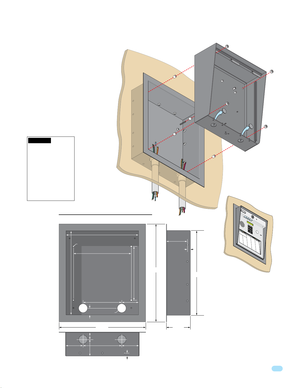
1.2.1 Surface Mount Recess Kit Installation for 1803 & 1810
7
8
9
4
5
6
1
2
3
0
1803 & 1810 surface mount units can be
recessed into a wall or pilaster by using the
optional surface mount recess kit if desired
(P/N 1803-150). This allows a recessed 1810
telephone entry system to have a lighted
keypad which the flush mount unit DOES
NOT have. The recess box gets installed in
the wall. Use appropriate hardware (not
included) to secure the box in the wall. Run
all necessary conduit (not included) to the
recess box. Slide the enclosure in the recess
box and secure it with the hardware included
in the kit. Be sure the unit is mounted
securely and is not subject to vibration from
closing doors or gates.
WARNING! If this entry
system is used to control a
vehicular gate with an
automatic gate operator, the
entry system must be
mounted a minimum of six
(6) feet away from the gate
and gate operator, or in
such a way that a person
cannot operate the entry
system and touch the gate
or gate operator at the same
time.
Mount In a Surface
Wall
Plastic Spacer
Mounting Screws (Not supplied)
Recess
Box
Locknut
Surface Mount
Enclosure
Knock-outs
1800-060 Issued 7-19
Version A
Recess Box
Front View
25” Dia. Mounting Hole
13.25”
1”
1.125”
2.625”
2.5”
Bottom View
11.25”
9”
6”
1.375” Dia.
13.375”
6”
Threaded Stud
2.625”
2.625”
.4”
8.5”
15.25”
Side View
3.2”
.4”
Mounting
Holes
.25” Dia.
3.625”
13.25”
1
2
3
4
5
7
6
8
9
0
N
A
M
E
A
d
a
m
s
J
A
k
i
n
s
M
A
n
n
e
s
e
N
CO
J
A
A
M
n
D
d
E
E
e
r
s
D
o
o
n
A
0
r
N
p
H
l
0
a
p
A
9
n
l
M
e
d
g
E
T
D
a
t
o
A
e
1
w
B
u
B
1
y
s
n
5
e
t
w
i
r
n
a
s
D
r
D
M
d
u
B
3
L
b
C
a
5
r
l
a
s
e
2
r
b
u
d
a
i
C
i
l
l
u
D
l
O
M
o
g
u
B
D
h
5
P
k
C
a
EN
5
e
B
s
a
s
1
s
r
n
D
J
e
E
y
2
n
B
P
C
9
g
6
C
e
0
A
O
h
5
j
o
ME
a
D
a
6
l
r
r
l
E
i
d
n
I
E
s
L
1
l
Jo
li
B
G
5
0
s
C
e
2
8
7
r
r
o
W
d
0
l
8
l
i
a
y
n
7
n
e
J
r
F
M
0
a
R
J
B
2
r
2
o
C
a
e
8
5
2
rd
g
r
o
0
n
1
o
r
en
3
a
d
F
r
u
d
F
l
L
0
a
ar
J
E
B
7
3
o
D
C
r
i
2
l
5
o
2
r
l
o
i
g
0
w
1
n
u
e
1
g
r
n
M
t
s
F
s
E
C
8
e
e
L
K
B
2
O
rn
n
2
C
l
r
8
e
D
4
4
o
B
a
r
i
0
9
E
a
k
n
n
i
4
e
d
n
D
r
e
s
G
T
z
3
G
a
K
B
4
S
0
r
4
D
n
r
2
f
2
4
7
o
s
e
S
B
r
o
wn
J
B
r
o
w
n
K
B
r
y
a
n
t
W
B
y
r
o
n
R
B
y
a
n
G
N
i
o
al
e
3
6
6
b
A
l
t
1
d
l
o
M
i
c
n
S
G
E
h
7
a
B
L
3
B
5
rr
0
a
D
3
6
2
0
R
m
e
a
2
4
3
a
e
n
b
9
u
e
i
e
s
B
J
G
l
e
s
4
e
L
4
D
R
6
1
n
a
D
1
4
7
t
1
R
n
a
r
7
7
2
d
y
e
w
2
i
D
g
M
l
s
e
G
6
r
J
o
L
1
B
7
2
n
a
D
2
3
6
9
R
z
n
e
a
6
3
2
d
e
L
l
3
e
m
e
a
r
z
h
H
s
in
a
9
H
a
L
S
e
g
1
4
b
8
a
D
C
t
4
M
0
4
2
o
e
R
n
i
2
4
D
9
1
3
D
2
4
2
D
3
1
3
D
3
2
1
1
7
O
r
8
l
8
n
g
e
l
f
D
1
st
e
s
P
S
E
l
s
d
r
H
e
o
5
g
a
A
L
m
4
8
m
i
e
e
2
0
1
R
v
u
i
B
m
0
3
l
0
i
o
l
n
8
o
R
4
e
l
e
l
1
n
r
i
n
H
D
V
1
M
s
e
L
2
0
n
e
A
0
2
3
d
S
w
i
1
6
x
2
r
c
i
i
4
o
s
2
h
x
8
n
u
B
K
H
s
7
D
i
t
L
r
3
e
9
d
u
2
r
9
0
S
c
o
A
8
S
6
6
i
e
m
d
8
8
el
i
7
i
e
n
B
H
y
1
i
i
c
M
t
8
3
J
k
c
6
a
3
8
h
S
P
o
n
0
8
8
e
J
n
c
6
8
l
i
l
i
c
k
D
o
n
n
e
D
o
n
t
e
3
e
n
H
c
i
2
k
i
G
M
P
tc
3
4
H
2
a
7
5
h
S
s
8
6
1
h
F
t
8
8
i
a
n
3
e
H
r
D
3
r
o
M
R
3
K
1
d
3
a
0
3
S
g
s
5
1
5
e
h
t
5
8
s
o
a
1
n
n
A
H
r
k
8
F
o
M
F
3
D
0
o
5
o
6
4
S
v
7
z
9
6
e
i
i
m
3
r
7
n
1
a
H
o
J
n
3
J
e
M
s
0
n
2
2
s
u
L
4
7
S
e
4
c
7
6
m
n
e
3
5
ra
i
5
D
t
J
h
0
o
J
M
J
6
h
1
4
n
u
2
9
S
0
s
l
2
5
o
i
o
n
5
4
m
n
5
B
J
a
M
0
o
c
N
0
h
h
0
ab
5
n
4
9
S
H
0
s
0
9
t
o
o
e
8
2
r
e
n
2
l
K
J
e
T
4
o
N
9
F
n
6
a
0
e
4
S
b
s
6
0
t
u
o
5
A
r
l
0
l
J
a
J
3
c
o
N
4
h
n
4
e
1
e
4
S
H
u
s
7
7
y
m
9
G
n
1
a
f
o
n
8
l
n
N
7
A
0
i
J
9
x
0
T
0
o
o
6
2
n
m
1
R
l
i
5
n
P
5
s
7
a
o
7
4
T
t
n
0
te
o
5
7
m
L
r
6
s
p
o
0
s
n
P
3
o
5
e
F
2
n
4
T
r
1
e
o
6
A
0
z
m
0
F
p
4
s
P
1
o
5
e
9
n
0
T
t
3
ro
1
y
S
3
l
e
l
4
l
r
i
A
Q
R
3
a
3
W
y
2
0
J
a
1
s
3
h
i
n
2
g
1
W
t
o
2
1
a
n
2
s
9
G
h
i
n
5
g
4
W
t
o
0
3
e
n
0
n
7
K
t
L
9
8
Wh
1
7
3
i
4
t
i
n
g
3
M
5
Wi
6
2
0
n
9
s
t
o
n
W
F
3
y
8
a
9
t
t
J
6
7
9
2
1
1
6
7
0
4
4
1
9
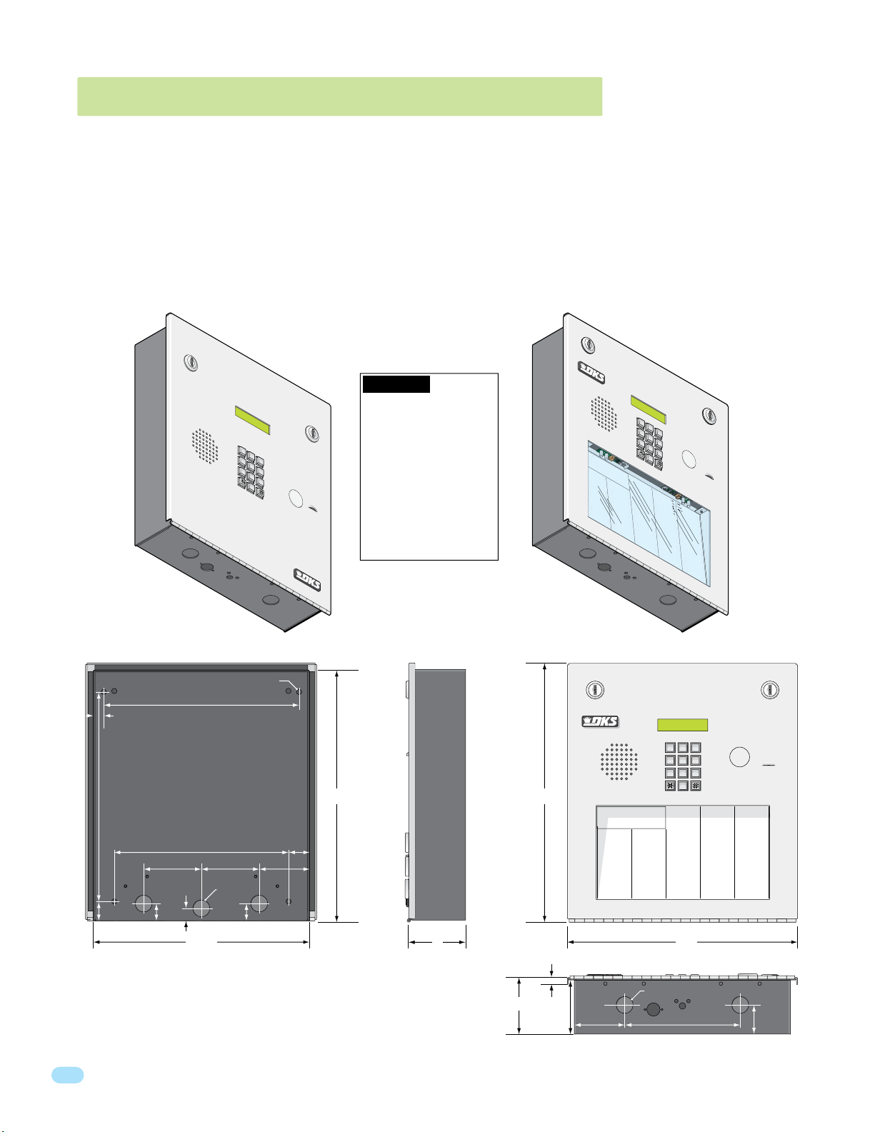
7
8
9
4
5
6
1
2
3
0
O
per
a
tin
g Instructions
cat
e
Code Number On Direct
or
y
ess
C
od
e Num
b
er
. I
f Line
Is
Busy
,
P
r
ess
A
ny Bu
t
ton
Hang-Up.
T
ry
Ag
a
in.
nt
er
On
“OP
EN” Display or
T
one
.
J
M
e
J
s
o
n
H
e
g
a
t
e
B
n
D
b
a
u
g
h
B
s
J
a
r
I
rl
in
J
rn
a
r
d
E
ll
in
g
s
L
ro
k
e
r
T
B
ro
s
e
S
B
ro
wn
J
B
ro
wn
K
B
ry
an
t
W
B
y
ro
n
R
B
y
a
n
G
0
0
9
1
1
5
3
5
2
5
5
1
6
5
6
0
7
8
2
2
1
3
2
1
2
4
9
4
7
6
0
0
3
1
1
2
2
9
2
8
2
2
4
9
1
3
2
4
2
3
1
3
3
2
1
1
7
C
OD
E
NA
ME
B
y
e
rs
M
C
a
rd
illo
P
C
arn
ey
P
C
o
l
lin
s
G
C
o
l
y
e
r
R
C
o
rd
u
la
D
C
o
u
rt
E
C
ra
in
s
G
Dalt
o
n
B
Da
n
i
el
s
R
Da
wl
s
J
D
eL
a
h
a
e
M
Di
ll
P
Di
ll
o
n
M
Di
x
o
n
D
Do
min
i
c
k
P
Do
n
i
c
k
P
Do
n
n
e
r
K
Do
n
t
e
r
F
8
0
7
5
0
3
5
0
1
4
0
4
4
6
1
2
4
9
7
7
2
6
3
3
4
8
1
1
0
4
3
2
2
0
6
8
8
8
8
5
1
8
3
5
8
4
6
7
7
6
5
9
5
4
9
9
2
C
ODE
NA
M
E
Do
r
l
a
n
d
T
Do
wn
w
a
rd
L
Du
b
re
u
il
M
Du
k
e
s
D
E
n
g
h
a
r
d
L
E
l
lis
W
F
a
ra
g
o
F
F
a
rr
o
w
M
F
e
rna
n
d
e
z S
Ga
r
f
i
e
ld
S
Garre
a
u
J
Ge
n
tr
y
M
Go
n
za
le
z H
Hab
e
r
f
e
ld
A
Ham
me
r
V
He
n
d
r
i
x
K
Hir
d
A
Hit
c
h
J
Hi
t
c
h
F
Ho
d
g
e
s
A
H
o
o
v
e
r
H
J
e
n
s
e
n
D
J
o
h
n
s
o
n
M
J
o
h
n
s
o
n
T
J
o
n
e
s
A
J
o
n
e
s
G
2
9
0
1
5
2
0
2
8
0
7
2
8
2
8
3
4
2
7
3
3
4
4
1
6
1
2
9
1
4
5
4
2
1
2
0
7
3
2
1
8
6
2
3
2
3
3
3
8
3
5
3
0
2
0
6
4
0
0
5
4
9
0
3
4
1
8
7
9
5
5
7
0
3
2
4
1
9
C
O
DE
N
A
ME
J
o
rd
a
n
M
J
o
rd
e
n
L
J
o
r
g
en
s
e
n
B
K
le
in
D
K
n
o
b
l
ic
h
B
L
a
mb
B
L
a
n
d
D
L
a
n
d
e
r
s
S
L
a
n
g
s
tr
o
m
B
L
e
v
i
n
e
D
L
e
w
is
B
L
u
c
id
i
B
Ma
n
c
i
n
i
G
Ma
s
t
i
n
D
Ma
s
t
o
n
F
Mo
zi
n
a
J
Muc
e
ra
J
Mulin
B
N
a
b
o
r
K
N
a
b
u
r
J
N
e
u
m
a
n
n
J
N
ix
o
n
R
P
at
t
e
r
s
o
n
F
P
erez F
P
et
ro
ll
i
A
R
a
y
J
8
0
3
0
2
6
9
9
6
3
3
8
4
7
6
1
0
1
0
6
9
2
4
7
1
2
2
0
4
0
6
4
0
4
4
7
0
0
6
7
4
5
5
4
6
5
0
1
3
3
0
2
1
1
5
4
3
9
8
7
3
5
2
R
e
mi
n
g
t
o
n
S
R
e
s
s
e
g
i
e
u
R
R
o
l
lin
s
A
Sc
h
u
st
e
r
S
S
ee
l
e
y
J
S
e
l
le
c
k
H
S
h
a
e
r
R
S
h
a
n
k
D
S
im
o
n
s
L
S
m
i
t
h
J
S
o
m
a
c
h
H
S
t
e
e
le
F
S
to
l
la
c
h
H
S
yn
fo
l
A
T
o
m
l
i
n
s
o
n
L
T
o
mps
o
n
A
T
o
mps
o
n
S
Ty
l
e
r
Q
W
a
s
h
i
n
g
to
n
G
W
a
s
h
in
g
t
o
n
K
W
e
n
t
L
W
h
i
ti
n
g
M
W
in
s
t
o
n
F
W
y
a
t
t
J
0
8
1
1
4
8
8
8
7
0
6
3
8
8
3
5
5
1
7
3
1
4
3
5
0
5
5
0
8
2
6
5
0
7
9
1
0
2
1
0
7
6
1
0
0
3
3
4
2
1
3
2
2
9
0
0
7
1
3
4
6
0
9
3
8
9
6
7
9
2
1
1
6
7
0
4
4
1
C
OD
E
7
8
9
4
5
6
1
2
3
0
1.3 1803 & 1810 Flush Mount Dimensions
9
6
3
0
Flush mount 1803 & 1810 are installed with a flush mount kit P/N 1814-165 (stainless) or 1814-166 (gold). Flush mount kits
are NOT INCLUDED with the flush mount entry system (See next page for flush mount kit installation).
DoorKing offers a self-standing lighted kiosk for the flush mount unit ideal for walk-up pedestrian applications P/N 1200-170
(See page 12 for self-standing kiosk installation).
The flush mount units may also be installed ON the surface of a wall with a flush mount surface mounting kit if desired P/N
1814-152 (silver only). Flush mount surface mounting kits are NOT INCLUDED with the flush mount entry system (See page 13
for flush mount surface mounting kit installation).
Flush mount 1803 & 1810 are installed into a wall/kiosk and can be mounted outside, exposed to the weather. It is preferred
that they have limited direct exposure to the weather. We suggest that when they are mounted outdoors, it is in a covered
protected area. Be sure the unit is mounted securely and is not subject to vibration from closing doors or gates.
WARNING! If this entry
system is used to control a
vehicular gate with an
automatic gate operator, the
entry system must be
mounted a minimum of six
(6) feet away from the gate
and gate operator, or in
such a way that a person
cannot operate the entry
system and touch the gate
or gate operator at the same
time.
1
.
Lo
cat
2
.
P
ress
t
o Hang-Up.
3.
En
t
NA
ME
A
d
a
ms
J
A
k
in
s
M
A
n
n
e
s
e
J
A
n
d
e
rs
o
A
p
p
l
e
g
A
u
s
t
i
n
B
a
ls
b
a
B
a
s
s
B
e
ja
r
B
e
rl
in
B
e
rn
B
i
ll
in
B
ro
B
ro
B
ro
B
B
B
O
per
e
Code Number On Direct
a
tin
C
g Instructions
od
e Num
er
b
On
er
T
ry
. I
Ag
“OP
f Line
or
a
EN” Display or
in.
y
Is
Busy
,
P
r
ess
T
C
one
OD
A
ny Bu
EN
.
n
H
0
0
A
9
ME
a
t
e
B
1
B
1
y
5
e
D
rs
M
3
C
5
a
2
rd
u
g
illo
h
B
5
P
C
5
arn
1
J
ey
P
6
C
5
o
6
I
l
lin
s
G
0
C
7
o
8
l
J
y
e
r
R
2
C
2
a
o
1
r
rd
d
E
u
la
3
D
C
2
o
g
1
u
s
L
rt
E
2
C
k
4
e
ra
9
r
in
T
s
G
4
Dalt
s
7
e
6
S
o
n
B
0
Da
wn
0
3
n
J
i
el
s
ro
1
R
Da
wn
1
2
wl
K
s
ry
J
2
D
an
9
eL
2
t
W
a
h
a
y
e
ro
8
Di
2
M
n
2
ll
R
P
B
y
a
4
Di
n
9
1
ll
G
o
n
M
3
Di
2
4
x
o
n
D
2
Do
3
1
min
i
c
3
k
Do
3
P
2
n
i
c
k
P
1
Do
1
7
n
n
e
r
K
Do
n
t
e
r
F
1810
1
2
3
4
5
7
6
8
9
0
NA
M
E
Do
r
l
a
t
n
ton
d
T
Do
wn
w
a
Du
rd
L
b
re
u
il
Du
M
C
O
k
DE
e
s
D
E
n
g
2
N
h
9
C
a
A
0
ODE
r
ME
d
E
L
l
lis
1
J
5
W
o
2
rd
8
0
a
F
7
n
a
ra
0
M
J
2
g
o
8
o
rd
5
F
0
e
F
3
n
a
L
rr
0
J
o
7
o
w
2
r
5
g
M
0
en
F
1
e
s
rna
8
e
K
2
n
8
le
n
B
4
d
in
0
e
Ga
4
z S
D
r
3
f
K
4
i
e
2
n
ld
4
o
6
b
S
Garre
1
l
ic
7
h
L
3
B
a
3
a
mb
2
u
4
J
Ge
9
B
n
4
L
tr
4
a
1
y
n
7
M
d
7
Go
2
D
6
n
L
1
za
a
2
le
n
6
d
3
z H
Hab
3
e
4
8
Ham
1
1
0
He
4
n
3
2
Hir
2
d
0
6
Hit
8
8
8
Hi
8
5
1
Ho
8
3
5
H
8
4
6
J
7
7
6
J
5
9
5
4
9
9
2
R
e
r
e
s
mi
9
L
S
1
r
f
e
ld
me
r
V
d
r
i
x
K
A
c
h
J
t
c
h
F
d
g
e
s
o
o
v
e
e
n
s
e
n
o
h
n
s
J
o
h
n
J
o
n
e
J
o
n
e
n
a
4
n
g
g
t
o
R
s
C
n
tr
e
A
5
4
2
1
2
0
7
3
2
1
8
6
2
3
2
3
3
3
A
8
3
5
r
H
3
0
D
0
6
o
n
M
0
s
o
n
T
4
s
A
3
s
G
OD
s
o
S
s
L
m
e
E
e
g
B
v
8
i
i
e
0
n
R
u
3
e
o
R
D
0
l
lin
L
8
e
1
s
w
0
A
2
is
Sc
6
B
h
1
u
L
4
st
u
8
c
9
e
id
r
9
S
6
i
S
ee
B
8
l
Ma
8
e
7
y
3
J
n
3
c
S
8
i
e
n
l
i
0
le
G
Ma
6
c
3
k
4
s
H
7
t
S
i
6
n
h
a
8
D
e
Ma
8
r
3
R
1
s
0
t
S
o
1
h
n
a
5
F
n
Mo
5
k
1
0
D
zi
6
S
n
9
im
a
7
J
o
Muc
3
n
2
4
0
5
9
0
4
1
8
7
9
5
5
7
0
3
2
4
1
9
1
s
2
4
L
e
S
7
ra
m
4
i
J
t
Mulin
3
h
5
J
1
2
S
2
o
B
m
0
N
5
a
5
a
c
b
0
h
o
4
S
H
r
0
t
e
K
0
e
N
8
le
2
a
F
b
6
u
4
S
r
0
to
J
6
l
la
N
5
0
e
c
u
h
4
m
4
S
H
7
a
yn
n
7
n
fo
N
9
1
ix
J
l
0
A
o
0
n
T
6
o
R
m
0
P
2
l
i
1
at
n
s
7
t
o
e
4
T
r
n
5
o
s
mps
L
o
0
n
P
7
6
erez F
F
o
5
n
4
T
A
6
o
mps
1
P
0
0
et
o
5
ro
n
0
Ty
S
1
ll
i
l
3
e
A
r
R
3
Q
4
a
y
3
J
3
W
0
a
2
s
1
h
3
i
n
2
g
1
W
to
1
a
n
2
s
G
2
h
9
in
5
g
4
W
t
3
o
e
n
0
n
K
0
t
7
L
9
8
W
7
h
1
i
ti
3
n
4
g
3
5
M
W
2
in
6
s
0
t
9
o
n
W
F
y
3
a
8
t
t
9
J
6
7
9
2
1
1
6
7
0
4
4
1
TELEPHONE ENTRY SYSTEM
OPERAT
1.
Locate Co
2.
Pr
ess
Pr
es
3.
Enter
1803
1
4
7
ING
de
Cod
Numbe
s
e Number. If Line is Busy,
“#” to Hang UP
on
To
ne
.
2
5
8
0
INSTRUCTIONS
r
o
n Directo
.
Tr
y Agai
3
6
9
ry
.
n
.
10.875”
1”
.5”
25” Dia. Mounting Hole
10.125”
9”
3”
.5”
.875”
3”
.875” Dia
.875”
11.25”
2.625”
1.125”
Side ViewBack View Front View
11223
44556
77889
0
13.5”13”
Operating Instructions
1. Locate Code Number On Directory
2. Press Code Number. If Line Is Busy, Press Any Button
to Hang-Up. Try Again.
3. Enter On “OPEN” Display or Tone.
NAME
CODE NAME
Adams J
009
Byers M
Akins M
115
Cardillo P
Annese J
352
Carney P
Anderson H
551
Collins G
Applegate B
656
Colyer R
Austin D
078
Cordula D
Balsbaugh B
221
Court E
Bass J
321
Crains G
Bejar I
249
Dalton B
Berlin J
476
Daniels R
Bernard E
003
Dawls J
Billings L
112
DeLahae M
Broker T
292
Dill P
Brose S
822
Dillon M
Brown J
491
Dixon D
Brown K
324
Dominick P
Bryant W
231
Donick P
Byron R
332
Donner K
Byan G
117
Donter F
3”
CODE NAME
NAME
Jordan M
Dorland T
290
Jorden L
Downward L
152
Jorgensen B
Dubreuil M
028
Klein D
Dukes D
072
Knoblich B
Enghard L
828
Lamb B
Ellis W
342
CODE
733
Land D
Farago F
807
441
Landers S
Farrow M
503
612
Langstrom B
Fernandez S
501
914
Levine D
Garfield S
404
542
Lewis B
Garreau J
461
120
Lucidi B
Gentry M
249
732
Mancini G
Gonzalez H
772
186
Mastin D
Haberfeld A
633
232
Maston F
Hammer V
481
333
Mozina J
Hendrix K
104
835
Mucera J
Hird A
322
302
Mulin B
Hitch J
068
064
Nabor K
Hitch F
888
005
Nabur J
Hodges A
518
490
Neumann J
Hoover H
358
341
Nixon R
Jensen D
467
879
Patterson F
Johnson M
765
557
Perez F
Johnson T
954
032
Petrolli A
Jones A
992
419
Ray J
Jones G
12”
.25”
.875” Dia
3”
2.75”
2.625”
6”
Bottom View
CODE NAME
CODE
023
Reese D
081
562
Reiger B
148
647
Remington S
887
736
Ressegieu R
063
408
Rollins A
883
803
Schuster S
551
026
Seeley J
731
996
Selleck H
435
338
Shaer R
055
476
Shank D
082
101
Simons L
650
069
Smith J
791
247
Somach H
021
122
Steele F
076
040
Stollach H
100
640
Synfol A
334
447
Tomlinson L
213
229
006
Tompson A
007
745
Tompson S
134
546
Tyler Q
609
501
Washington G
389
330
Washington K
679
211
Went L
211
543
Whiting M
670
987
Winston F
441
352
Wyatt J
1.5”
10
1800-060 Issued 7-19
Version A
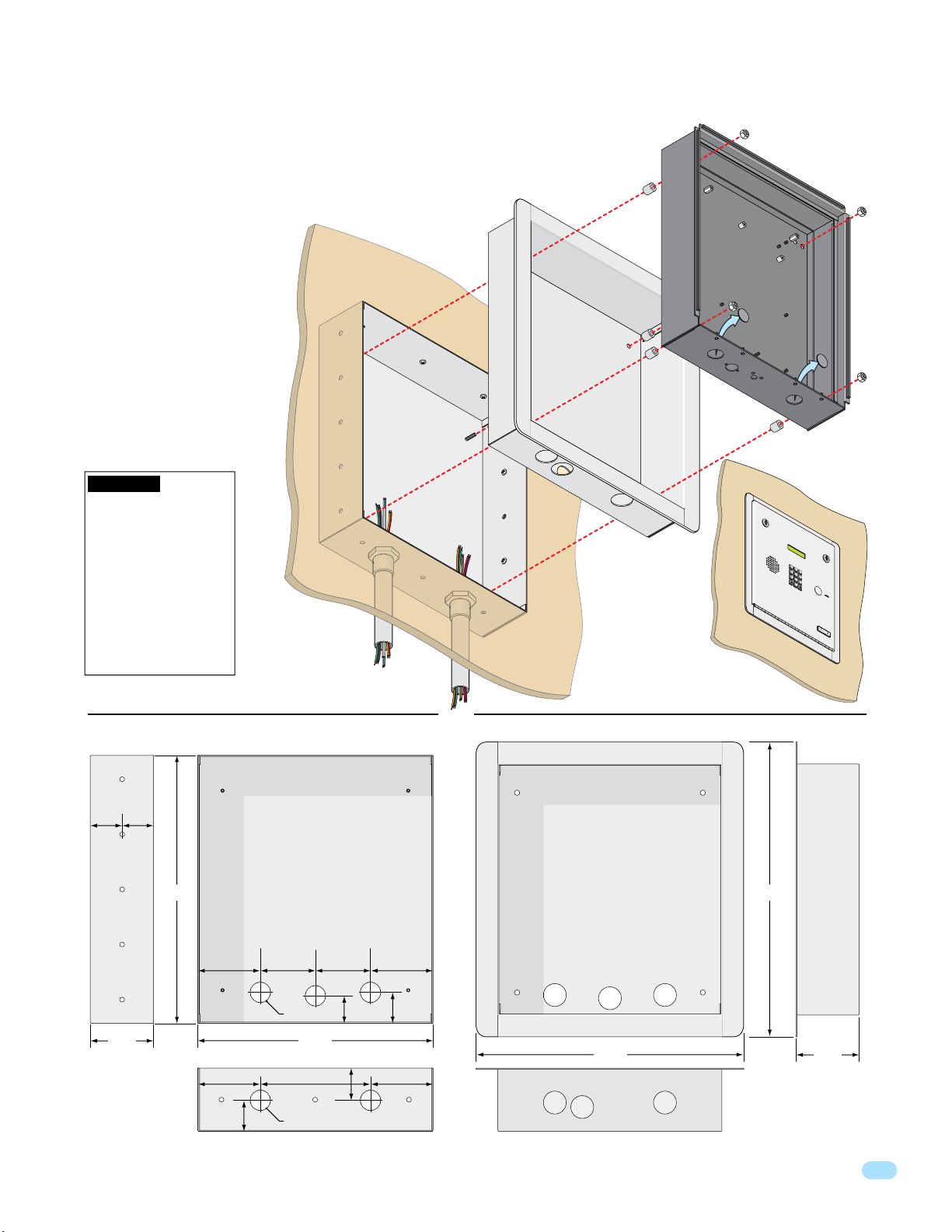
7
8
9
4
5
6
1
2
3
0
1.3.1 Flush Mount Kit Installation for 1803 & 1810
The flush mount kit has two
parts; the rough-in box and the
trim ring. The rough-in box is
installed in the wall first. Use
appropriate hardware (not
included) to secure the box in the
wall. Run all necessary conduit
(not included) to rough-in box.
Slide the trim ring into the
rough-in box. Slide the enclosure
in the trim ring and secure them
all together with the hardware
included in the kit. Be sure the
unit is mounted securely and is
not subject to vibration from
closing doors or gates. See
previous page for flush mount
enclosure dimensions.
WARNING! If this entry
system is used to control a
vehicular gate with an
automatic gate operator, the
entry system must be
mounted a minimum of six
(6) feet away from the gate
and gate operator, or in
such a way that a person
cannot operate the entry
system and touch the gate
or gate operator at the same
time.
Mount In a Surface
Wall
Mounting Screws
(Not supplied)
Rough-In
Box
Plastic Spacer
Trim
Ring
Locknut
Flush Mount
Enclosure
Knock-outs
T
E
L
E
PH
O
NE
E
N
T
RY
1
2
4
5
7
8
0
O
1.
PE
L
oc
RAT
2.
at
P
e
re
C
I
ode
N
s
s
P
G
C
re
I
o
Num
3.
s
de
N
s
Enter
ST
“#”
N
ber
um
R
t
on
ber
on
o
H
D
.
T
ang
one.
I
f
Line
U
P
.
Tr
y
SYS
T
E
M
3
6
9
UCT
irect
I
O
N
o
r
S
y
i
.
s
B
us
A
gain.
y
,
M
O
DE
L
1
80
3
Side View
1.74” 1.71”
Mounting
Holes
.25” Dia.
3.45”
1800-060 Issued 7-19
Version A
Rough-In Box Trim Ring
Front View
Threaded Stud
14.6” 16”
1.5”
3.4”
1.685”
Mounting
Hole
3.4”
3”
3”
1.125” Dia
12.8”
3.4” 3.4”
1.74”
6”
1.8”
1.125” Dia
Front View
Hole for Threaded Stud
14.7”
Bottom ViewBottom View
Side View
3.45”
11

1.3.2 Self-Standing Lighted Kiosk Installation for 1803 & 1810
The flush mount kit (Sold separately) is installed into the self-standing
kiosk (P/N 1200-170) to secure the flush mount 1803 or 1810 in place.
Secure the rough-in box in the kiosk. Run all necessary wires to rough-in
box. Slide the trim ring into the rough-in box. Slide the enclosure in the
trim ring and secure them all together with hardware included in the kit.
Plastic Spacer
Locknut
Flush Mount
Enclosure
60”
Rough-In
Box
Trim
Ring
Knock-outs
WARNING! If this entry
system is used to control a
vehicular gate with an
automatic gate operator, the
entry system must be
mounted a minimum of six
(6) feet away from the gate
and gate operator, or in
such a way that a person
18
.5”
10
”
12
cannot operate the entry
system and touch the gate
or gate operator at the same
time.
1800-060 Issued 7-19
Version A

1.3.3 Flush Mount Surface Mounting Kit Installation for 1803 & 1810
7
8
9
4
5
6
1
2
3
0
Flush mount unit (See page 10 for flush
mount enclosure dimensions) can be
mounted ON a wall or pilaster and NOT IN
the wall by using the optional flush mount
surface mounting kit (P/N 1814-152). This
is useful when cutting a large hole into a
wall or pilaster would be very difficult
(marble or granite for example) .The flush
mount surface mounting kit is a trim ring
that fits around the flush mount enclosure. The enclosure and trim ring get
installed directly on the wall using
appropriate hardware (not included) after
running all necessary conduit to the
enclosure. Be sure the unit is mounted
securely and is not subject to vibration
from closing doors or gates.
Examples of some
small holes in the
wall that may be
needed, depending
on how you choose
to run the wiring.
to junction box
Trim Ring
Mount On a Surface
Wall
Trim Ring
Conduit run
Conduit
sweep
run
Mounting Screws
(Not supplied
Flush Mount
Enclosure
Knock-outs
T
E
L
E
O
1.
PE
Locat
2.
P
e
r
ess
P
re
3.
ss
Ent
e
r
)
PH
O
N
E
E
N
T
RY
SYST
E
M
1
2
3
4
5
6
7
8
9
0
RA
T
C
I
ode
N
G
C
I
o
N
de
N
u
m
ST
“#”
N
b
er
um
R
t
on
ber.
U
on
o
CT
H
D
T
an
irect
one.
I
f
I
g
O
Line
U
N
or
P.
S
y.
i
T
s
r
y
Busy
A
ga
,
i
n.
M
O
DE
L
1
8
0
3
WARNING! If this entry
system is used to control a
vehicular gate with an
automatic gate operator, the
entry system must be
mounted a minimum of six
(6) feet away from the gate
and gate operator, or in
such a way that a person
cannot operate the entry
system and touch the gate
or gate operator at the same
time.
1800-060 Issued 7-19
Version A
.375”
.875”
1”
12”
1.5”
1.5”3” 3” 3”
1.125”
1.125” Sq
Bottom View
Side ViewFront View
13.5”
2.625”
1”
.875”
1.125” Dia
13
 Loading...