

DoorKing 1504-096, 1506-086, 1504-086, 1506-096 Installation And Owner's Manual
Installation/Owner’s Manual
Models 1504 / 1506
1504
1506
P
u
sh
Butt
o
n
To
C
a
ll
Pu
sh Butto
n
To
C
a
l
l
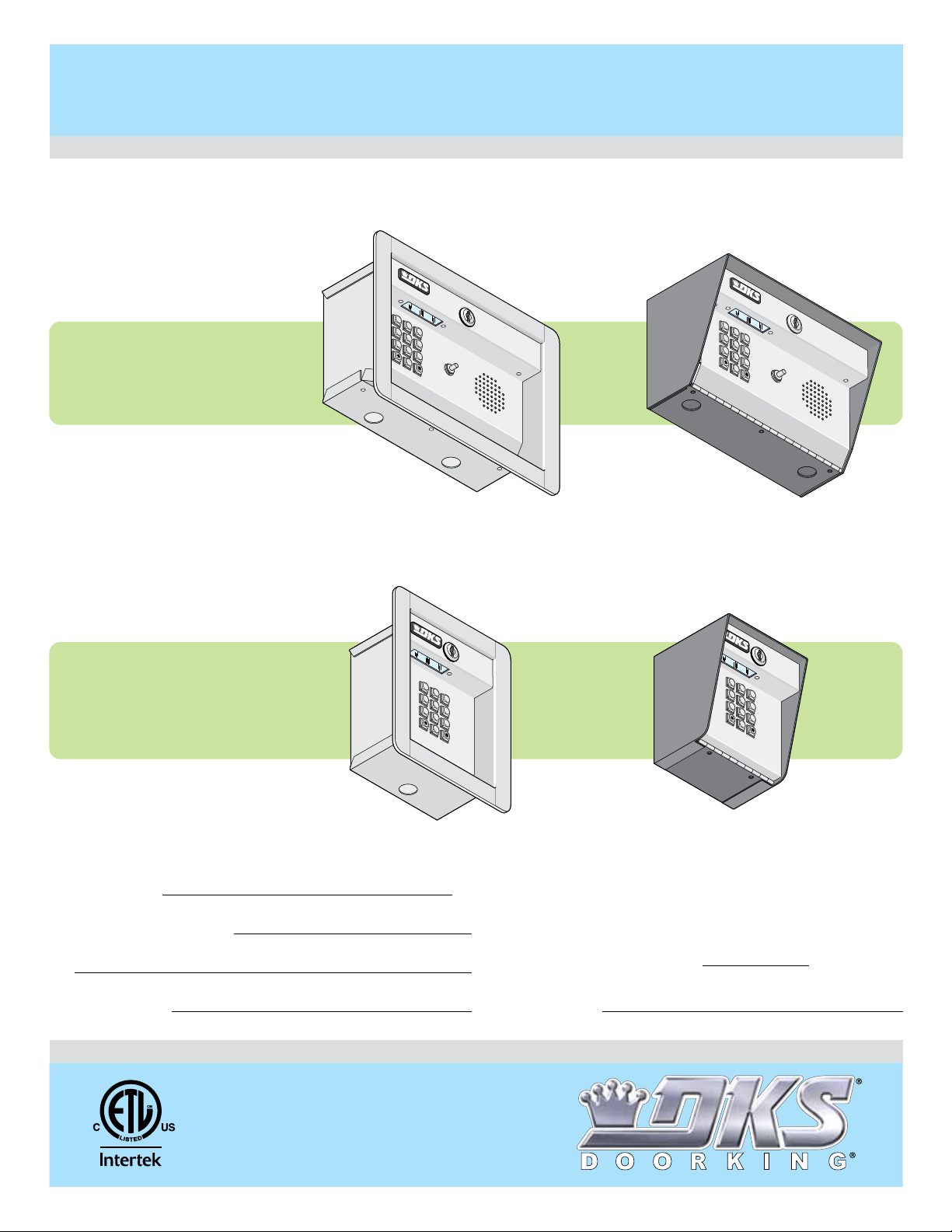
Programmable Stand Alone Digital Keypad Entry Devices
Models 1504 / 1506
Models 1504 / 1506
Use this manual for circuit board 1506-010 Revision G or higher.
Flush Mount
1
2
3
4
5
Push Button
6
7
8
9
To
0
Cal
l
1504
1504
with Intercom
1504-096
Flush Mount
1506-065-K-6-17
Control a main entry point plus an additional entry point.
Surface Mount
1
2
3
4
5
Push Button
6
7
8
9
To Call
0
1504-086
Surface Mount
1506
1506
Date Installed:
Installer/Company Name:
Phone Number:
Leave Manual with Owner
UL Listed
1
2
3
4
5
6
7
8
9
0
1506-096
Circuit Board
Serial Number
and Revision Letter:
Copyright 2017 DoorKing, Inc. All rights reserved.
1506-086
Model Number
1
2
3
4
5
6
7
8
9
0
Copyright 2009 DoorKing, Inc. All rights reserved.


TABLE OF CONTENTS
SPECIFICATIONS
1504 Specifications
1506 Specifications
Important Notices
SECTION 1 - INSTALLATION
1.1 Remove Faceplate from Cabinet
1.2 Surface Mount
1.3 Flush Mount
1.4 Terminal Wiring
1.5 1504 AiPhone Intercom Station Connections
1.6 Secondary Keypad Wiring
SECTION 2 - PROGRAMMING
2.2 Relay Strike Time
2.3 X Strikes for Invalid Entry Code Attempts
2.4 Programming Four-digit Entry Codes
2.5 Erase a Four-digit Entry Code
2.6 Erase ALL Four-digit Entry Codes
2.7 Four-digit Entry Code Divide Number
2.8 Programming Five-digit Entry Codes
2.9 Erase a Five-digit Entry Code
2.10 Erase ALL Five-digit Entry Codes
2.11 Five-digit Entry Code Divide Number
2.12 Hold Boundary Programming
2.13 Time ZONE 1 Boundary Programming
2.14 Time ZONE 2 Boundary Programming
2.1 Re-Programming the Master Code
2
2
3
4
4
4
5
5
6
7
8
9
9
9
9
10
10
10
10
11
11
11
11
12
12
12
SECTION 3 - OPERATING INSTRUCTIONS
3.1 Four-digit Entry Codes
3.2 Five-digit Entry Codes
3.3 Request to Exit Input (Terminals 1 and 12)
3.4 Door Open Input (Terminals 2 and 12)
3.5 Hold Feature Operation
3.6 Time Zone Operation
SECTION 4 - MAINTENANCE
4.1 Troubleshooting
4.2 Log Tables
1506-065-K-6-17
13
13
13
13
13
14
15
16
16
17-19
1
1504 SPECIFICATIONS
P
u
sh
B
ut
t
o
n
To
C
a
ll
Push Button
To Call
Pu
sh
B
u
t
t
o
n
T
o
C
a
ll
Push Button
To Call
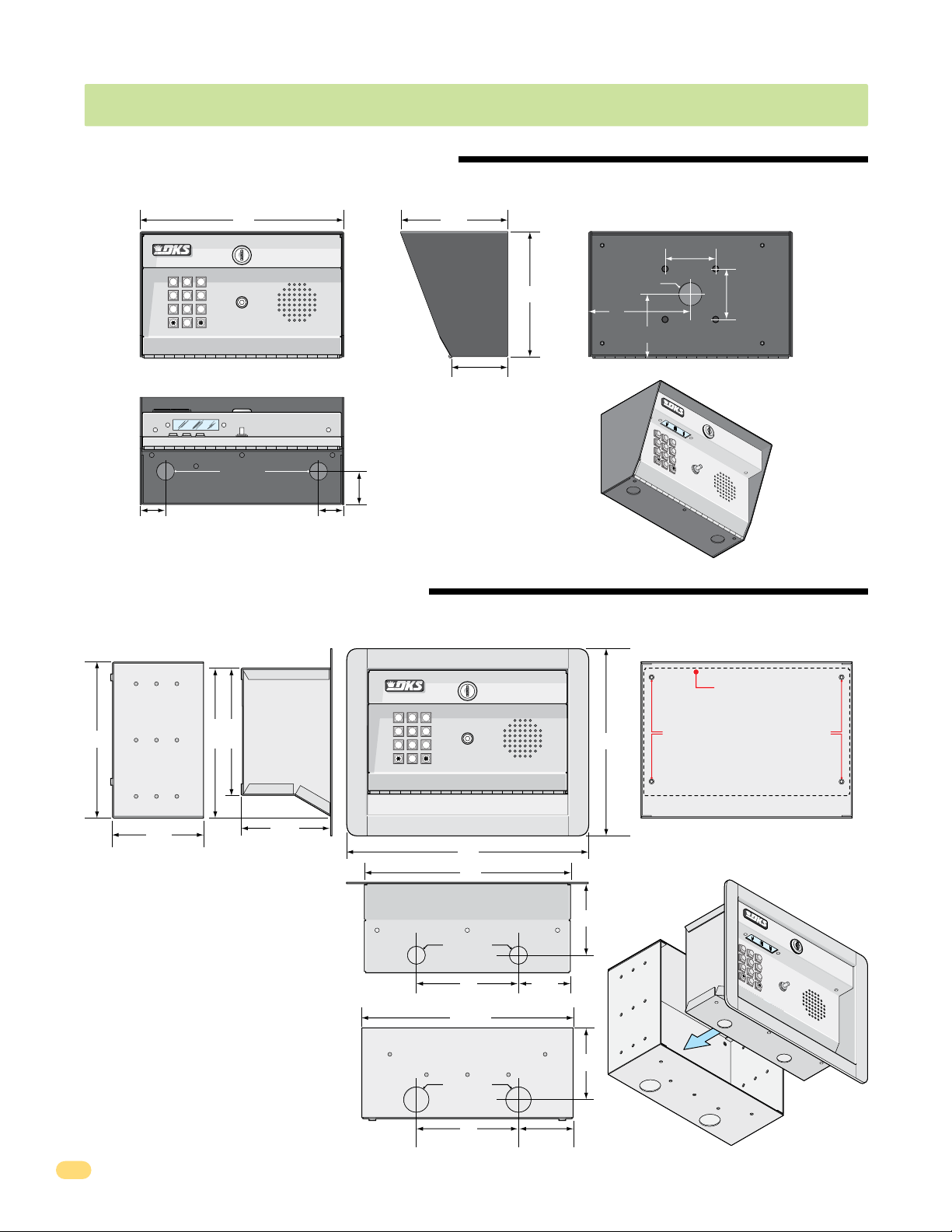
1504 Surface Mount Dimensions
P/N 1504-086
Side ViewFront View
10” 5.25”
Back View
2.5”
1 2 3
4 5 6
7 8 9
Push Button
To Call
0
Mounting Note:
Can be mounted on a DoorKing
gooseneck mounting post.
875” Dia
1.75”
1.125”1.125”
Bottom View
1504 Flush Mount Dimensions
P/N 1504-096
Side Views
Rough-In Box
7.5”
7.25”
6.25”
Flush Box
1 2 3
4 5 6
7 8 9
0
2.875”
Push Button
To Call
6.125”
1.125” Dia
5”
Front Views
9.25”
2.5”
3”
1
2
3
4
5
Push Button
6
7
8
9
T
o Call
0
Flush Box
Bolt holes (4) to secure flush box
inside rough-in box.
4.5”
4.25”
Flush Box
Rough-In Box
12”
10”
Flush Box
.875” Dia
5” 2.5”
Bottom Views
10.25”
Rough-In Box
2
1.25” Dia
5”
2.625”
3.5”
3.5”
Rough-In
x
Bo
Flus
ox
B
1
h
2
3
4
5
Push Button
6
7
8
9
T
o Call
0
1506-065-K-6-17
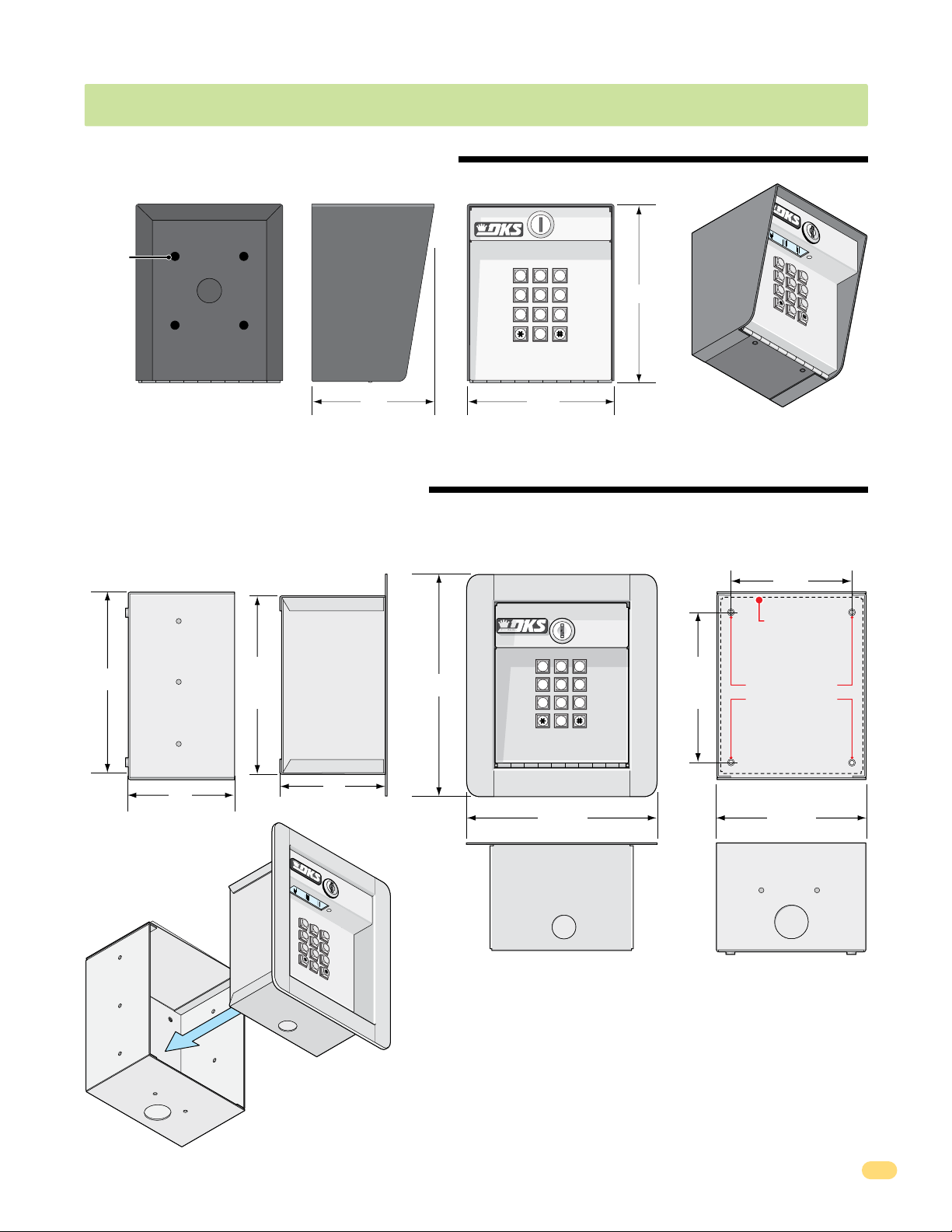
1506 SPECIFICATIONS
1506 Surface Mount Dimensions
P/N 1506-086
Back Side Front
Mounting
Holes
1/2”
Knock-out
Mounting Note:
Can be mounted on a DoorKing
gooseneck mounting post.
1506 Flush Mount Dimensions
P/N 1506-096
Side Views
Rough-In Box
7”
Flush Box
6.625”
8.375”
1 2 3
4 5 6
7 8 9
0
5.25”4.5”
1 2 3
4 5 6
7 8 9
1
2
3
4
5
6
7
6.5”
8
9
0
Front Views
4.25”
Flush Box
4.375”
0
Bolt holes (4)
to secure flush
box inside
rough-in
box.
Rough-In
Box
1506-065-K-6-17
4”
Flush
Box
4”
1
2
3
4
5
6
7
8
9
0
Flush Box
7.125”
.875” Dia
Flush Box
Rough-In Box
5.625”
1.25” Dia
Rough-In Box
Bottom Views
3
Important Notices
• Prior to starting the installation, become familiar with the instructions, illustrations and wiring diagrams in this manual.
• Never mount this device to a moving gate or gate panel, or next to a gate that causes vibration to the fence, such as a spring-
loaded pedestrian gate. Continuous vibration from moving or slamming gates can cause damage to the unit in time.
• If this system is used to activate an automatic vehicular gate operator, it must be mounted in such a way that the user
cannot come into contact with the gate or the gate operator when the device is used. We recommend that the unit be
installed a minimum of 6 feet away from the gate and gate operator.
• Always disconnect power when performing service on the system.
• If the unit is mounted outdoors, be sure that the wiring to the unit is designed for direct underground burial, even if the wire is
run inside a conduit.
• Surge suppression is recommended on the low voltage input power line.
• Instruct the end user on the safe and proper operation of this device.
• Instruct the end user to read and follow these instructions. Instruct the end user to never let children play with or operate
any access control device. This Owner’s Manual is the property of the end user and must be left with them when
installation is complete.
SECTION 1 - INSTALLATION
Do not mount the 1504/1506 keypad to a moving gate, or immediately next to a gate panel or pedestrian gate. Continuous
vibration from slamming gates and vibration can cause damage to the system over time.
WARNING! If the keypad is used to activate a vehicular gate operator, it must be mounted a minimum of 6 feet away from
the gate and gate operator, or in such a way that the user cannot come into contact with the gate or gate operator while
using the device.
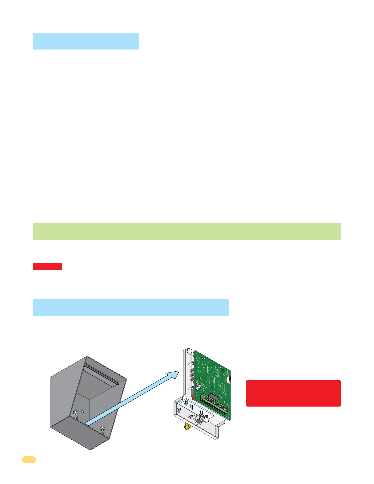
1.1 Remove Faceplate from Cabinet
1. Open housing with key (surface or flush mount). 2. Remove locknuts from hinge on faceplate to remove faceplate.
Locknuts
1506-010
13 14
N
O
E
OD
R
C
E
T
MAS
Discharge any static BEFORE
removing the faceplate by
10 11 12
9
8
67
5
34
12
touching a proper ground device.
Store faceplate in a safe place
during installation.
4
1506-065-K-6-17
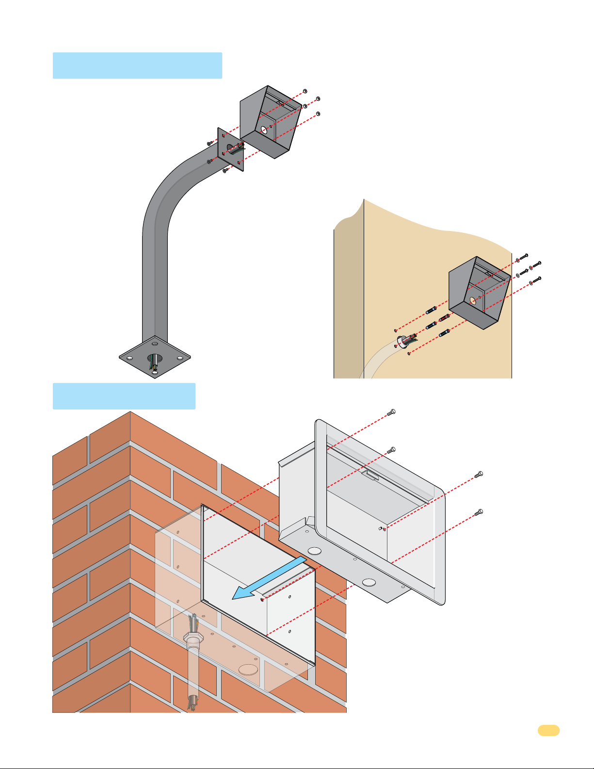
1.2 Surface Mount
See spec page in front of
this manual for dimensions
about your model.
Mount on a Post
Use existing 4 holes in surface
mount cabinet box to bolt on a
DoorKing mounting post.
Use the hardware that is
supplied with the
mounting post.
Run ALL wires that will be
needed during the cabinet
installation and connect to
14-pin terminal. See Section
1.4 Terminal Wiring.
IMPORTANT: Be sure to clean out the cabinet of any
debris that can cause a short.
All necessary wiring should be connected to the 14-pin
terminal. See Section 1.4 Terminal Wiring.
Surface mount cabinet can be mounted directly to a
wall or pilaster. They can be post mounted using a
DoorKing mounting post (there are several different
styles available). Be sure keypad is securely mounted
and is not subject to continuous vibration from
closing doors or gates.
Mount Directly
to a Wall or Pilaster
Note: A gooseneck
mounting post
anchored in concrete
does not make a
good ground.
1.3 Flush Mount
Mount in a Pilaster,
Use the 4 existing holes in
the cabinet. Run conduit
inside of wall or pilaster. Use
appropriate hardware to
mount the cabinet (Not
supplied). Be sure that the
mounting hardware does not
protrude into the cabinet
where it could cause a short.
Wall or Kiosk
Flush
Box
Plastic screw anchors
for masonry if required.
(Not supplied)
1/2” Conduit
Bolt flush box into
the rough-in box with
4 supplied bolts.
See spec page in
front of this manual
for dimensions about
your model.
1506-065-K-6-17
Conduit
in Wall
Rough-In Box
Mount rough-in box into the pilaster, wall or
kiosk. Run conduit inside wall into bottom of
rough-in box if desired. Use appropriate
hardware (Not supplied) to secure the rough-in
box in place.
IMPORTANT: Be sure to clean out the cabinet of
any debris that can cause a short.
All necessary wiring should be connected to the
14-pin terminal. See Section 1.4 Terminal Wiring.
5
 Loading...