

Page 1

EN
DEFRNL
CLIMATE
AIR CONDITIONERS
MCS T6, MCS T12, MCS T16
Marine Air Conditioner
Operating manual . . . . . . . . . . . . . . . . . . . . . 4
Bootsklimaanlage
Bedienungsanleitung . . . . . . . . . . . . . . . . .38
Climatiseur pour bateau
Notice d’utilisation . . . . . . . . . . . . . . . . . . .77
Bootairco
Gebruiksaanwijzing. . . . . . . . . . . . . . . . . . 117
Page 2

Page 3
MCS T6, MCS T12, MCS T16
1
2
8
3
9
4
7
6
5
1
3
Page 4

EN
MCS T6, MCS T12, MCS T16
Please read this instruction manual carefully before first use, and store it in
a safe place. If you pass on the product to another person, hand over this
instruction manual along with it.
Contents
1 Explanation of symbols. . . . . . . . . . . . . . . . . . . . . . . . . . . . . . . . . . . . . . . . . . .5
2 Safety instructions . . . . . . . . . . . . . . . . . . . . . . . . . . . . . . . . . . . . . . . . . . . . . . .5
3 Target group for this manual. . . . . . . . . . . . . . . . . . . . . . . . . . . . . . . . . . . . . . .6
4 Proper use . . . . . . . . . . . . . . . . . . . . . . . . . . . . . . . . . . . . . . . . . . . . . . . . . . . . .6
5 Technical description . . . . . . . . . . . . . . . . . . . . . . . . . . . . . . . . . . . . . . . . . . . .6
6 Operating elements . . . . . . . . . . . . . . . . . . . . . . . . . . . . . . . . . . . . . . . . . . . . .7
7 Operating . . . . . . . . . . . . . . . . . . . . . . . . . . . . . . . . . . . . . . . . . . . . . . . . . . . . .8
8 Programming . . . . . . . . . . . . . . . . . . . . . . . . . . . . . . . . . . . . . . . . . . . . . . . . . 15
9 Troubleshooting . . . . . . . . . . . . . . . . . . . . . . . . . . . . . . . . . . . . . . . . . . . . . . 24
10 Maintenance . . . . . . . . . . . . . . . . . . . . . . . . . . . . . . . . . . . . . . . . . . . . . . . . . 32
11 Warranty . . . . . . . . . . . . . . . . . . . . . . . . . . . . . . . . . . . . . . . . . . . . . . . . . . . . 35
12 Disposal . . . . . . . . . . . . . . . . . . . . . . . . . . . . . . . . . . . . . . . . . . . . . . . . . . . . . 35
13 Technical data . . . . . . . . . . . . . . . . . . . . . . . . . . . . . . . . . . . . . . . . . . . . . . . . 36
4
Page 5
EN
MCS T6, MCS T12, MCS T16 Explanation of symbols
1 Explanation of symbols
WARNING!
!
Safety instruction: Failure to observe this instruction can cause fatal or
serious injury.
CAUTION!
Safety instruction: Failure to observe this instruction can lead to injury.
!
NOTICE!
A
Failure to observe this instruction can cause material damage and impair
the function of the product.
NOTE
Supplementary information for operating the product.
I
2 Safety instructions
The manufacturer accepts no liability for damage in the following cases:
•
Faulty assembly or connection
•
Damage to the product resulting from mechanical influences and excess voltage
•
Alterations to the product without express permission from the manufacturer
•
Use for purposes other than those described in the operating manual
2.1 General safety
CAUTION!
•
!
Electronic devices are not toys!
Keep electrical appliances out of reach from children or infirm persons.
Do not let them use the appliances without supervision.
•
Persons (including children) whose physical, sensory or mental capabilities or lack of experience and knowledge prevents them from using
the appliance safely should not use this appliance without initial supervision or instruction by a responsible person.
•
Use the device only as intended.
•
Do not make any alterations or conversions to the device.
5
Page 6

EN
Target group for this manual MCS T6, MCS T12, MCS T16
•
Installation and repairing of the air conditioner may only be carried out
by qualified personnel who are familiar with the risks involved and the
relevant regulations. Inadequate repairs can lead to considerable hazards. For repair service, please contact the service centre in your country (addresses on the back).
3 Target group for this manual
This operating manual is for air conditioner users.
4Proper use
The Marine Climate System is an air conditioning system designed for use on boats
or yachts. It can cool down or warm up the interior of the boat or yacht.
5 Technical description
The Marine Climate Systems MCS T6, MCS T12 and MCS T16 are marine air conditioners which can be used for variable air conditioning inside a boat or a yacht. They
can cool and warm the room.
The Marine Climate System consists mainly of the air conditioning unit and a control
panel. A refrigerant is circulating through the system which is seawater cooled.
6
Page 7
EN
MCS T6, MCS T12, MCS T16 Operating elements
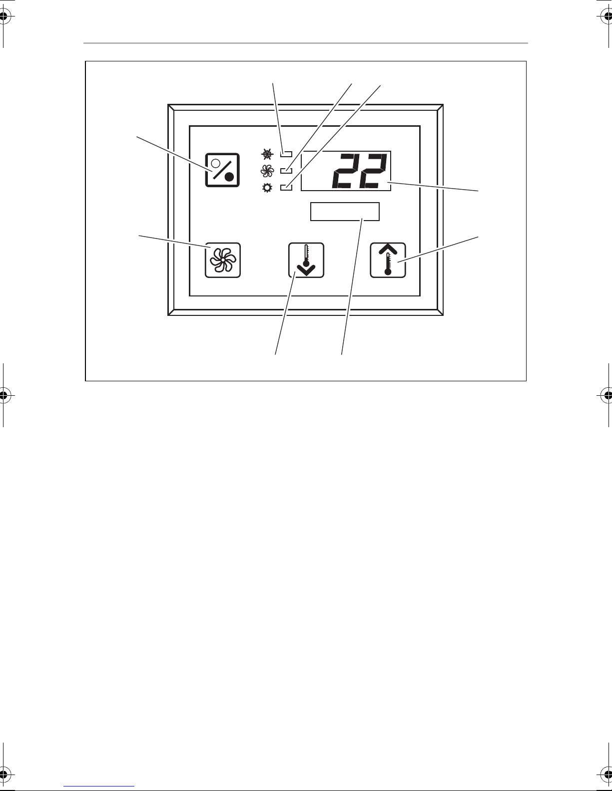
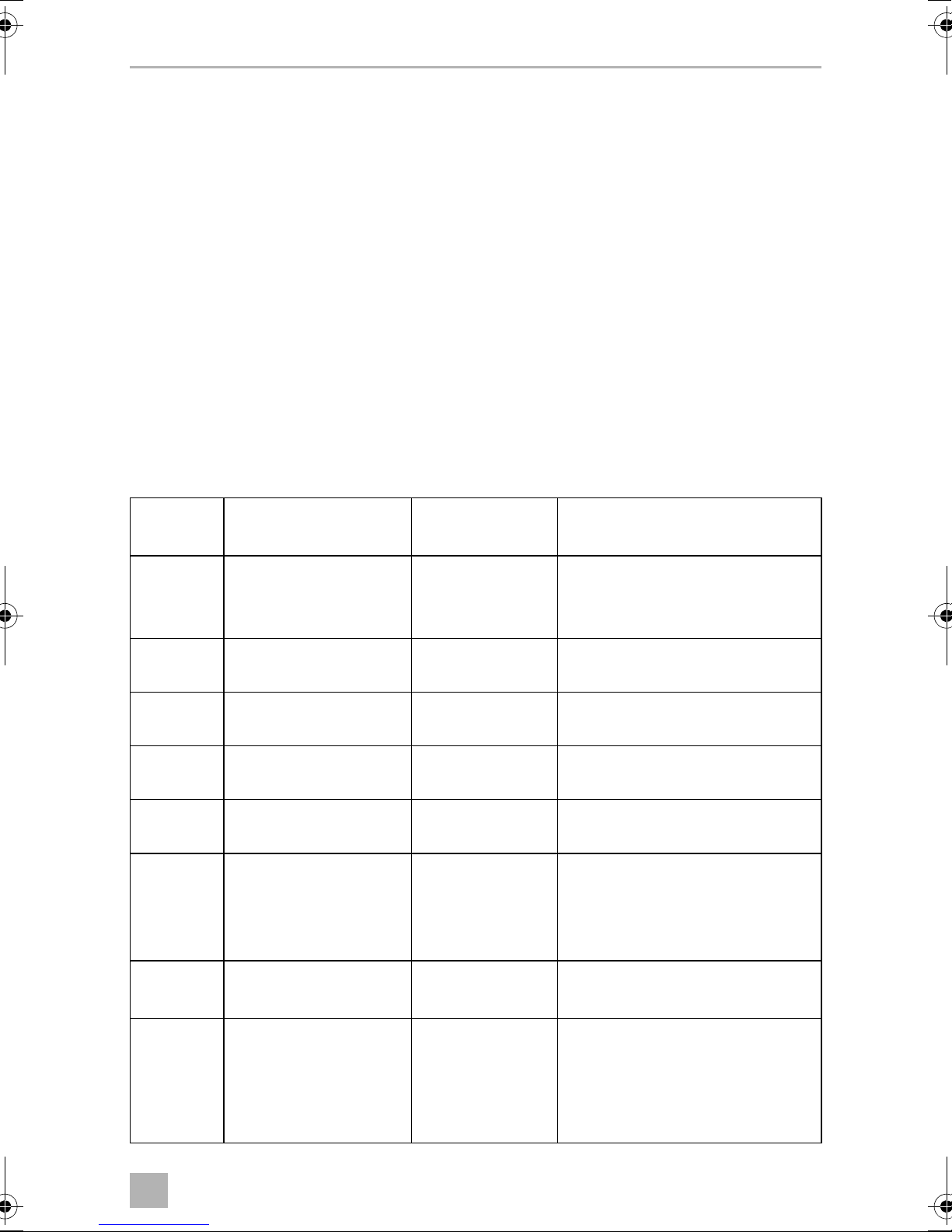
6 Operating elements
6.1 Control Panel
Key to fig. 1, page 3:
Item Name Description
1 Power Button Press and release to toggle between the On and Off Modes.
2
3 Down Button Press and release to display the set point.
4 Faceplate sensor The faceplate sensor will read the room temperature unless a
5 Up Button Press and release to display the set point.
6 Display The inside air temperature is displayed when the control is on.
Fan Button
Press to advance through the available fan settings. “1”(lowest)
through “6” (highest) indicates Manual Fan Speeds.
The letter “a” indicates automatic fan operation selected.
Press and hold the Down Button to decrease the set point. Set
point is decreased 0.5 °C or 1 °F each time the button is
depressed.
remote air sensor is installed.
Press and hold the Up Button to increase the set point. Set
point is increased 0.5 °C or 1 °F each time the button is
depressed.
The set point is displayed when either Up or Down Button is
pressed.
The display also indicates program information and fault
codes.
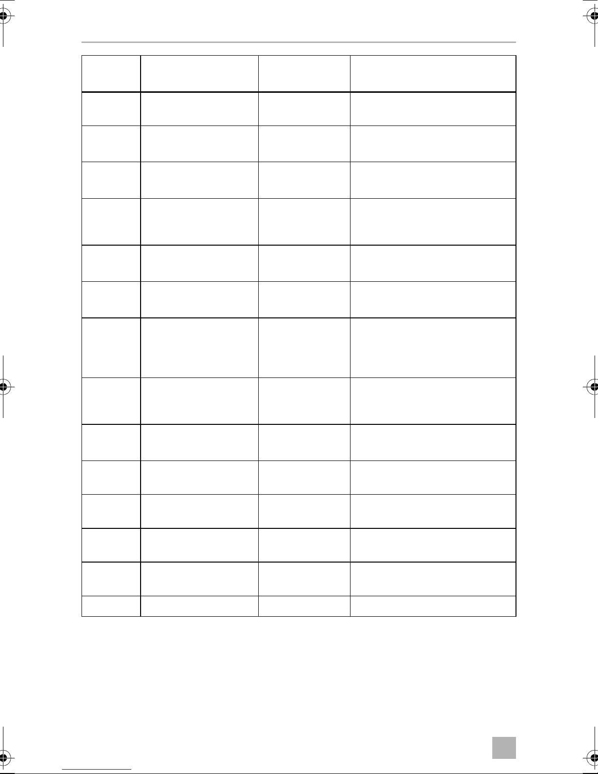
7 LED “Heat
Mode”
8 LED “Fan
Indicator”
9 LED “Cool
Mode”
When the control resumes operation after a power interruption
all the display LEDs will turn on for one second. This is normal
operating condition and is referred to as Power On Reset.
This LED is lit when
– the Heat Only Mode is selected
– or the unit is in a heating cycle.
This LED is lit when a Manual Fan Speed is selected.
This LED is lit when
– the Cool Only Mode is selected
– or when the unit is in a cooling cycle.
7
Page 8
EN
Operating MCS T6, MCS T12, MCS T16
6.2 Dual Button Functions
Up and Down Buttons
•
While in the On Mode: Simultaneously press the Up and Down Buttons to display outside air temperature providing the optional outside air temperature sensor is installed.
•
While in the Program Mode: Simultaneously press the Up and Down Buttons
to set new program defaults.
Power and Down Buttons
•
While viewing the service fault history log: Simultaneously press the Power
and Down Buttons to clear the fault history log (see “Service History Log” on
page 14).
•
While in the On Mode: Simultaneously press the Power and Down Buttons to
enter the Dehumidification Mode (see “Dehumidification Mode” on page 11).
7Operating
7.1 Initial startup
NOTICE!
A
➤ Ensure seawater intake ball valve (seacock) is open.
➤ Turn on air conditioner circuit breaker.
➤ If the seawater pump has its own circuit breaker, turn that on.
➤ Press the Fan Button (fig. 1 2, page 3).
✓ This energizes the fan.
➤ Verify that the fan is running and that there is steady airflow out of the supply-air
grille.
Do not turn the unit off and immediately turn it back on. Allow at least
30 s for refrigerant pressure equalization.
➤ Select a temperature set point lower than the current cabin temperature.
✓ This starts the compressor and seawater pump.
8
Page 9

EN
MCS T6, MCS T12, MCS T16 Operating
➤ Check for a steady solid stream of seawater from the overboard discharge.
➤ If the unit does not appear to be operating properly, refer to troubleshooting
guidelines (“Troubleshooting” on page 24).
7.2 Overview
Power On
➤ Press the Power button (fig. 1 1, page 3) once to engage the system.
✓ The display indicates room temperature when the system is on and is blank when
the system is off.
Set Temperature
➤ Press the Up or Down button (fig. 1 3 and 4, page 3) to set the desired room
temperature.
The set point can be viewed by momentarily pressing and releasing the Up or
Down button.
Fan Speed
Fan-speed operation is automatic, allowing fan speed to decrease as the set point
temperature is approached in the Cool Mode. The fan operates at low speed when
set point is satisfied.
➤ Use the Fan button (fig. 1 2, page 3) to select manual fan speeds.
You can program the fan to run only when cooling or heating is required. Normally
the automatic fan-speed operation is reversed in the Heating Mode, however, the
fan can be programmed to operate the same as in the Cooling Mode.
Memory
The control’s nonvolatile memory requires no batteries or backup power. When
power is lost, the operating parameters are retained indefinitely. When power is
restored, the control resumes operating as last programmed.
9
Page 10

EN
Operating MCS T6, MCS T12, MCS T16
7.3 Modes of Operation
Off Mode
When the Marine Climate System is in the Off Mode, all control outputs are turned
off. Program parameters and user settings are saved in nonvolatile memory.
On Mode
When the Marine Climate System is in the On Mode, power is supplied to the appropriate outputs and the display indicates the current state of operation. The operating
and program parameters resume based on those stored the last time the unit was
operating.
Cool Mode
When Cool Mode is selected, the Cool Mode LED is lit and the cooling systems are
operated as required. When the temperature drops below the set point, the system
will not automatically switch to the Heat Mode.
Heat Mode
When the Heat Mode LED is lit, only the heating systems are selected and operated
as required. Should the temperature rise above the set point, the system will not
automatically switch to the Cool Mode.
Automatic Mode
Automatic Mode provides both heating and cooling as required. The Heat or Cool
LED will be lit according to the mode required.
Temperature in a given mode is maintained within 1.1 °C (2 °F) of set point, however
a 2.2 °C (4 °F) difference is required to allow the Marine Climate System to change
modes.
Once the mode changes temperature will be maintained within 1.1 °C (2 °F) of set
point.
Manual Fan Mode
Manual Fan Mode allows to select the desired fan speed manually. When a manual
fan speed has been selected, the Fan LED will be lit. Manual Fan Mode is sometimes
preferred when room temperature is constantly changing due to varying heat loads.
The fastest fan speed is represented by “6”, the slowest represented by “1”.
10
Page 11
EN
MCS T6, MCS T12, MCS T16 Operating
➤ Press and hold the Fan Button during normal operation to select one of the six
manual fan speeds available.
Circulation Mode
When the system is off at the control panel the fan can be used to only circulate the
air.
➤ Press and hold the Fan Button when the display is off until the desired speed
number appears in the window.
➤ Release the Fan Button.
✓ The fan will run at the selected speed circulating the air without heating or
cooling.
➤ Press the Power Button once to cancel the Circulation Mode and enter the On
Mode.
Dehumidification Mode
➤ While in the On Mode simultaneously press the Power and Down Buttons.
✓ The first cycle will start in one minute.
➤ Press the Power Button to end the Dehumidification Mode.
✓ The “HU1” mnemonic code is displayed while in the Dehumidification Mode.
Program Mode
NOTE
The program mode can only be entered from the Off Mode.
I
The Program Mode is used to adjust the systems operating parameters to suit the
particular needs of individual users. The Program Mode is also used to tailor the air
conditioning system for the most efficient operation within an installation.
Variables such as ducting, sensor location and system layout affect the system operation. The Marine Climate System is shipped with factory default settings which are
stored in permanent memory and can be recalled at any time.
11
Page 12
EN
Operating MCS T6, MCS T12, MCS T16
7.4 Operating the Marine Climate System
NOTICE!
A
I
➤ Press the Power Button (fig. 1 1, page 3) shortly to engage the system.
✓ The display indicates room temperature when the system is on and is blank when
the system is off.
Do not turn the unit off and immediately turn it back on. Allow at least
30 s for refrigerant pressure equalization.
NOTE
When powering on the Marine Climate System, press and
immediately release the Power Button in order to not unintentionally
entering Program Mode.
If the Program Mode is entered unintentionally, any subsequent presses
of the Up or Down Button will change the P-1 parameter setting, which
can result in improper system operation.
➤ Press the Down Button (fig. 1 3, page 3) or Up Button (fig. 1 5, page 3) to
choose the desired set point.
✓ The display indicates room temperature when the system is on and is blank when
the system is off.
✓ The thermostat is now set to maintain a constant temperature.
➤ Set the desired room temperature by pressing the Up or Down Button.
The set point can be viewed by momentarily pressing and releasing the Up or
Down Button.
The Marine Climate System has nonvolatile memory requiring no batteries or backup
power. When power is lost the operating parameters are retained indefinitely. When
power is restored, the Marine Climate System resumes operating as last programmed.
Automatic fan speed operation allows fan speed to decrease as room temperature is
approached in the Cool Mode. The fan will operate at low speed when set point is
satisfied.
Manual fan speeds can be selected with the Fan Button.
The fan can be programmed to run only when cooling or heating is required. Normally the automatic fan speed operation is reversed in the Heating Mode, however,
the fan can be programmed to operate the same as in the Cooling Mode.
12
Page 13

EN
MCS T6, MCS T12, MCS T16 Operating
7.5 Automated Factory Self Test Program
The Marine Climate System software provides a self test program to facilitate factory
testing of the entire air conditioning system. Once the self test program is activated,
the test cycle will continue until the AC power is interrupted or the Power Button is
pressed once which returns the system to the Off Mode.
➤ Activate the self test program by pressing the Power Button while turning on the
AC power.
➤ Release the Power Button while the display indicates “888” and all LEDs are lit.
✓ The Marine Climate System is now in the self test program.
✓ “tSt” appears in the display while in the self test program.
Once activated the self test software will continuously execute the following procedure:
•
Turn on in the Heat Mode and supply heating for 10 min.
•
Stop heating and run the fan only for 5 min.
•
Switch to Cool Mode and continue cooling for 10 min.
•
Stop cooling and run the fan only for 5 min.
•
Return to step one and continue until interrupted.
The self test program will continue until the power is interrupted or the test is halted
by pressing the Power Button once.
13
Page 14
EN
Operating MCS T6, MCS T12, MCS T16
7.6 Service Tools
Hour Meter
Total compressor cycle time is saved in EEPROM every six minutes of continuous
compressor running time. Cycles less than six minutes are discarded to conserve
memory and allow the most flexible hour-meter possible.
To view the hour meter proceed as follows:
➤ Turn off the AC power.
➤ Press the Down Button and hold it.
➤ Restore AC power.
✓ After Power-On Reset is complete, the following appears in the display:
– “Hr” is displayed for one second.
– The display blanks out for one second then displays the thousands of hours
for three seconds.
– The display blanks out for one second then displays the hundreds units for
three seconds.
✓ The unit returns to the last operating state before power was removed.
Maximum recorded time is 65,536 hours, the meter stops and can only be reset by
a service technician.
Service History Log
The Marine Climate System records and remembers the eight most recent faults.
Each time a fault is detected, a one hour timer is started.
Three consecutive faults within that hour cause system shut down, lock out and display the fault code. During that hour, to conserve memory, the same recurring fault
is not recorded in the service history log. Continuous operation for one hour without
the same recurring fault clears that fault counter but the event remains in the service
history log until overwritten. Should a different fault be detected during the hour, it
will be entered into the service history log.
The following events are entered into the service history log:
•
High Freon Pressure
•
Low Freon Pressure
•
Air Sensor Fault
14
Page 15
EN
MCS T6, MCS T12, MCS T16 Programming
To view the service history log proceed as follows:
➤ Turn off the AC power.
➤ Press the Fan Button and hold it.
➤ Turn on the AC power.
➤ Once Power On Reset is completed (display indicates “888” and all LEDs are lit)
release the Fan Button.
✓ The display will flash the most recent fault detected, followed by the event chro-
nology number.
➤ To view other events detected press either the Up or Down Button.
➤ To clear the service history log simultaneously press the Power and Down But-
tons.
➤ To exit the service history log
– press either the Power, the Up or the Down Buttons or
– wait thirty seconds without pressing any button.
8Programming
8.1 Entering Program Mode
➤ Press and hold the Power Button while in the Off Mode until the letter “P”
appears in the display.
✓ The characters “P1” followed by the parameter setting, appear in the display.
✓ The Marine Climate System is now in the Program Mode.
NOTE
I
8.2 Changing Program Parameters
➤ Increment from one program parameter to the next by pressing the Fan Button.
➤ Press the Up and Down Buttons to select the data or set the desired limits for the
parameter being programmed.
The Marine Climate System will exit the Program Mode and return to the
Off Mode if no programming is attempted for one minute.
15
Page 16
EN
Programming MCS T6, MCS T12, MCS T16
8.3 Saving New Program Parameters
NOTE
I
➤ Simultaneously press the Up and Down Buttons to save the new program param-
eters.
✓ This will set the new program defaults.
Factory defaults shown in the “Programmable Parameters Table” on
page 17 may be reset manually (see “Restore Memorized Default Settings” on page 17).
8.4 Exiting the Program Mode
There are two methods to exit the Program Mode.
➤ Press the Power Button
✓ The Marine Climate System will return to the Off Mode.
… or
➤ Do not press any buttons and do not attempt any program changes for one
minute.
✓ The Marine Climate System will exit the Program Mode.
8.5 Software Identification
The software version of the Marine Climate System is identified for one second prior
to the exit from the Program Mode. The software identification number, e.g. (“A12”)
will appear in the display for one second, then the Marine Climate System will return
to the Off Mode.
NOTE
I
Should there be any reason to contact Dometic about the system or programming the Marine Climate System be sure to have the software identification number and air conditioning unit serial number available. The
serial number may be found on the typeplate.
16
Page 17
EN
MCS T6, MCS T12, MCS T16 Programming
8.6 Restore Memorized Default Settings
The memorized default settings can be restored as follows.
➤ Enter the Program Mode.
➤ Set P-17 to “rSt”.
➤ Exit the Program Mode.
✓ The software version number (e.g. “A12”) appears in the display.
✓ The memorized default settings are restored and the Marine Climate System
returns to the Off Mode.
8.7 Programmable Parameters
Programmable Parameters Table
Program
number
P-1 Operating Mode 0 0 = Automatic mode
P-2 High Fan Speed Limit
P-3 Low Fan Speed Limit
P-4 Compressor Staging Time
P-5 Temperature Sensor
P-6 Failsafe 3 0 = Minimum protection
Description Default Range
1 = Cool only mode
2 = Heat only mode
95 65 – 95
(arbitrary units)
55 30 – 64
(arbitrary units)
15 5 – 135 s
Delay
Calibration
Ambient
Te m p e r a t u r e
Ambient 10 °F, –12,2 °C
1 = Continuous, no display
2 = Continuous, with display
3 = Four failures, reset required
P-7 Low AC Voltage Shut-
down (Volts)
P-8 De-Icing Cycle 1 OFF
115 V – OFF
220/230 V – OFF
75 – 105
175 – 205
1 = On with 5 °F, –15 °C faceplate
sensor differential
2 = On with 7°F, –13,9°C faceplate
sensor differential
17
Page 18
EN
Programming MCS T6, MCS T12, MCS T16
Program
number
P-9 High Water Temperature
P-10 Display Brightness
P-11
P-12 Cycle Pump With
P-13 Reverse Fan Speeds Dur-
P-14 Continuous Fan or Cycle
P-15 Reverse Cycle Heating or
Description Default Range
Limit (°F)
Control
º
Display
Compressor or
Continuous Pump
ing Heating Mode
Fan with Compressor
Electric Heat Only Option
Installed (cooling only
units)
F or ºC
OFF 100 – 150
9 4 = Low
13 = Maximum
F F = Fahrenheit displayed
C = Celsius displayed
OFF OFF = Cycle with compressor
On = Continuous pump
rEF nor = Normal fan operation
rEF = Reversed fan in heating
con CYC = Cycle fan with compressor
con = Continuous fan operation
nor nor = Reverse cycle heating
ELE = Electric heater installed
P-16 Fan Motor type selection
Shaded Pole or Split
Capacitor.
P-17 Reset Memorized
Programming Defaults
P-18 Reserved for Future
Option
P-19 Reserved for Future
Option
P-20 Filter Threshold
(x10 hours)
P-21 Current Filter Time
(x10 hours)
P-22 Voltage Calibration (Volts) AC Voltage –
SC SP = Shaded pole fan motor
nor rSt = Reset defaults
––
––
00 00 – 250
x10 Hours Using
Current Filter
SC = Split capacitor fan motor
nor = Normal
–
18
Page 19
EN
MCS T6, MCS T12, MCS T16 Programming
NOTE
I
P-1: Operating Mode
The following operating modes can be selected:
•
Automatic Mode by selecting “0”
•
Cool Only Mode by selecting “1”
•
Heat Only Mode by selecting “2”
P-2: High Fan Limit
Should any programming problems or confusion occur, reset the Memorized Default Settings by entering the program mode and setting P-17
to “rSt”.
If recent programming changes were made but not saved, the reset will
return to the last saved defaults, which could differ from the factory
defaults.
The upper fan speed limit can be adjusted for various motors. The high fan limit is
adjusted with the system installed and operating. The values range from 65 through
95, arbitrary units.
➤ Use the Up and Down Buttons to select the desired speed.
– Increase the number for a higher fan speed.
– Decrease the number to lower the fan speed.
P-3: Low Fan Limit
The low fan limit determines the lowest output allowed for the low fan speed. The
values range from 30 through 64, arbitrary units.
➤ Use the Up and Down Buttons to select the low fan limit.
– Increase the number for a higher fan speed.
– Decrease the number to lower the fan speed.
NOTE
I
Once the high and low fan speed limits are set, the unit will automatically
readjust the remaining speeds to produce three equally spaced fan
speeds in both Automatic and Manual Fan Modes.
19
Page 20

EN
Programming MCS T6, MCS T12, MCS T16
P-4: Compressor Staging Time Delay
The compressor staging delay is provided for installations where more than one
system operates from the same power source. Setting different staging delays allows
compressors to start at different times when power is interrupted.
Units should be staged 5 s apart. The minimum delay is 5 s and the maximum is
135 s.
P-5: Temperature Calibration
Use this feature to calibrate the ambient sensor.
➤ Select P-5.
✓ The ambient temperature appears in the display.
➤ Use the Up and Down Buttons to set the correct reading.
✓ The temperature in the display will increase or decrease as required.
P-6: Failsafe Level
There are four failsafe levels (see “Failsafe and Fault Handling Codes” on page 28).
P-7: Low AC Voltage Shutdown
Use this feature to shut down the unit if the voltage drops to a dangerously low level.
By default it is off, but it can be set from 175 – 205. This feature works immediately at
start up, but while running will require a 5 min delay before displaying a fault to
prevent nuisances.
The fault code is “LAC”.
P-8: De-Icing Cycle
The Marine Climate System is equipped with a de-icing cycle to prevent ice build up
on the evaporator coil during extended periods of cooling operation. Installation
variables such as grille sizes, length of ducting, insulation R factors and ambient temperatures determine the cooling run time required to achieve set point. Customer
usage may substantially increase run times by operating the system with the hatches
and doors open.
Programming an unrealistic set point (e.g. 18.3 °C/65 °F) and leaving the door open
will usually cause the evaporator to ice up on warm humid days.
De-icing is accomplished by using an algorithm that closely monitors the room air
temperature in repeating 10 min intervals during a cooling cycle.
20
Page 21
EN
MCS T6, MCS T12, MCS T16 Programming
The de-icing feature has two different, selectable behavior modes when it is used in
conjunction with the control panel’s built-in room air temperature sensor. It attempts
to compensate for any temperature discrepancy that the faceplate sensor may experience. Although this discrepancy is not typical, installation variables such as where
the control panel is placed inside the room (e.g. near an open door or in direct sunlight) can affect how accurately it can read the actual room temperature.
By default with P-8 set to “1” (ON), the algorithm is applied assuming the faceplate
sensor may be reading the room temperature as much as 2.8 °C (5 °F) greater than
the actual evaporator temperature.
With programmable parameter P-8 set to “2”, the temperature differential that is
applied to the faceplate sensor reading is increased to 3.9 °C (7 °F) for even more
extreme installations. Setting P-8 to “2” should only be used if a setting of “1” does
not prevent evaporator ice from forming.
Alternately, the installation of an optional alternate air temperature sensor (located in
the return air path) will greatly increase the effectiveness of the de-icing feature, and
this option should be considered whenever the faceplate sensor cannot read the
room temperature accurately.
P-9: High Water Temperature Limit
Use this feature to shut down the unit if the water in condenser coil rises to a dangerously high level.
By default it is off, but it can be set between 100 and 150 °F.
The fault code is “PLF”.
P-10: Display Brightness Control
The display brightness can be adjusted from 4 (dimmest) to 13 (brightest).
P-11: Fahrenheit or Celsius Selection
The default setting is “°F”. Select “°C” for Celsius. Celsius readings are displayed in
tenths, e.g. 22.2.
P-12: Cycle Pump With Compressor
The pump can also be programmed to operate continuously or cycle on demand.
➤ To program continuous operation select “On”.
21
Page 22
EN
Programming MCS T6, MCS T12, MCS T16
P-13: Reverse Automatic Fan Speeds During Heating
The automatic fan speeds can be reversed during Heating Mode. The fan will speed
up as the set point is approached. Lowering the fan speed when the cabin is cold
increases head pressure and helps raise supply temperature. The fan switches to low
speed when the set point is satisfied and the compressor cycles off.
Normal fan operation is represented by “nor”.
➤ To reverse fan speeds in heating, select “rEF”.
P-14: Cycle Fan with Compressor
The fan can be programmed to run continuously when the system is on or can be
allowed to cycle with the compressor.
The default is “con”, continuous fan.
➤ To cycle the fan with the compressor select “CYC”.
NOTE
I
P-15: Reverse Cycle or Electric Heat
➤ Do not change the default parameter.
P-16: Fan Motor Selection
I
The fan motor can also be programmed to operate with shaded pole (SP).
➤ To program operation with shaded pole fan motor select “SP”.
When used with optional electric heat the fan will remain on 4 min after
the heater cycles off.
NOTE
The unit’s High Velocity (HV) blower has a Split Capacitor (SC) fan
motor. The default is “SC” in order for the blower to work at peak
efficiency.
22
Page 23

EN
MCS T6, MCS T12, MCS T16 Programming
P-17: Reset Memorized Defaults
The default programming parameters can be reset as follows:
➤ Select “rSt”.
✓ This restores the programmable parameters to the default values.
The default parameters listed in the “Programmable Parameters Table” on page 17
may be altered by the installing dealer or end user. Once new defaults are entered
and memorized the factory defaults will be overwritten. The original factory program
parameters as listed in the table may be restored manually.
P-18, P-19: Reserved for Future Option
P-20: Filter Threshold
This feature is to remind you to change the air filter on a unit. The units are x10 hours.
By default it is off, which is designated with a “00”, but it can be set between 100 and
2500 hours. After the unit has reached its threshold time, it will display a “FIL” remind
1 s every 10 s.
P-21: Current Filter Time
This feature is used to display the amount of time the current filter has been on the
unit. The units are x10 hours.
➤ In order to reset this parameter, simply press the Up or Down Button.
P-22: Voltage Calibration
This feature displays the voltage reading as seen by the display. Calibrating this
parameter will provide a more accurate voltage when calculating low voltage for P-7.
It will display a live reading of the voltage.
➤ Manipulate the reading by pressing the Up or Down Button.
23
Page 24
EN
Troubleshooting MCS T6, MCS T12, MCS T16
9 Troubleshooting
9.1 General Troubleshooting
Problem Possible Reason Solution
System will not start. Air conditioning unit circuit breaker is
off.
Control is not turned on. Turn control on.
Wrong wiring at terminal strip. Check wiring diagram and correct if
Push-on butt connectors became
disconnected during installation.
Input line voltage is insufficient. Check power source (shore/genera-
Fan is not running. – See corresponding section in “Con-
Turn circuit breaker on at ship’s
panel.
necessary.
Disconnect power supply and open
electric box.
Check wiring diagram, correct if necessary.
tor) for proper voltage.
Check wiring and terminals for
proper sizes and connections.
Verify with a volt-meter that the
power at the unit is the same as the
power source.
trol Panel Troubleshooting” on
page 30.
24
Page 25
EN
MCS T6, MCS T12, MCS T16 Troubleshooting
Problem Possible Reason Solution
No cooling or heating. Temperature set point is satisfied. Lower or raise set point.
Obstructed seawater flow. Clean seawater strainer.
Check for obstructions at speed
scoop thru-hull inlet.
Check for a good steady flow from
the overboard discharge.
Seawater pump may be air-locked. Remove hose from pump discharge
to purge air from line.
Loss refrigerant gas. Check air conditioning unit for refrig-
erant oil leakage.
Call service technician.
Seawater temperature too high for
cooling or too low for heating.
Seawater temperature will directly
affect air conditioning unit’s efficiency.
This air conditioning unit can effectively cool your boat in water temperature up to 32.2 °C (90 °F) and heat
in water temperatures as low as
4.4°C (40°F).
25
Page 26
EN
Troubleshooting MCS T6, MCS T12, MCS T16
Problem Possible Reason Solution
No cooling or heating
(contn’d).
Fan coil is iced (in cooling). See below.
Fan is not running. See corresponding section in “Con-
trol Panel Troubleshooting” on
page 30.
Seawater plumbing is air-locked. Ensure that seawater plumbing is
installed per the guidelines in the
Installation Manual.
The Marine Climate System is programmed for Cool or Heat only, or
mechanical control thermostat is
rotated too far towards either Cooler
or Warmer setting.
High pressure switch open (in cooling) due to improper seawater flow.
Strainer or intake may be plugged,
seacock may be closed.
High pressure switch open (in heating) due to improper airflow.
Set P-1 to the desired value or rotate
the mechanical control thermostat.
Check seawater hose for kinks or collapses.
Verify pump operation.
Check pump circuit breaker if appli-
cable.
Remove any obstructions in return air
stream.
Clean return air filter and grille.
Check for crushed or restricted duct-
ing (ducting must be as straight,
smooth and taut as possible).
High-pressure switch is open in heating mode.
Compressor’s thermal overload is
open due to either of the above reasons.
No cooling Control panel may not be in “cool”
position.
Coil iced. See below.
No heating. Unit is “cool only”, or if reverse cycle,
reversing valve may be stuck.
System may cycle on high-pressure if
seawater temperature is above
12.8 °C (55 °F).
Compressor needs to cool down.
Turn system off for a while (it may take
up to three hours to reset thermal
overload).
Reset control panel.
Tap reversing valve lightly with rubber mallet while unit is in heat mode.
Call for service if that does not correct the problem.
26
Page 27
EN
MCS T6, MCS T12, MCS T16 Troubleshooting
Problem Possible Reason Solution
Low airflow. Airflow is blocked. Remove any obstructions in return air
stream.
Clean return air filter and grille.
Check for crushed or restricted duct-
ing, ducting must be as straight,
smooth and taut as possible.
Fan Coil is iced. See below.
Fan coil is iced. Thermostat set point is too low. Check setting on control panel.
If setting is extreme for conditions,
raise set point until unit cycles off to
give coil time to thaw.
Improper airflow. Remove any obstructions in return air
stream.
Clean return air filter and grille.
Check for crushed or restricted duct-
ing.
Ducting run must be as straight as
possible; remove any excess ducting.
See the “Control Panel Troubleshooting” on page 30 for reprogramming options.
Water coil is iced in the
Heating Mode.
System runs
continuously.
Supply air is short-cycling. Redirect supply air so that is not
blowing into the return air stream.
Seal any air leaks on duct.
Humidity level too high. Close hatches and doors.
When all else fails. Switch air conditioning unit to heat
until ice melts or use hair dryer to
melt.
Seawater temperature is below
4.4 °C (40 °F).
Set point temperature is improperly
set: too low for cooling or too high
for heating.
Porthole or hatches open. Close all port holes and hatches.
Shut down system to prevent damage to condenser.
Allow coil to defrost.
Raise or lower set point.
27
Page 28

EN
Troubleshooting MCS T6, MCS T12, MCS T16
Problem Possible Reason Solution
System runs
continuously (contn’d).
Short cycling
compressor
Seawater temperature too high for
cooling or to low for heating.
Improper air sensor location. See corresponding section in “Con-
Cold supply air returning directly to
return air grille.
Seawater temperature will directly
affect the air conditioning unit’s efficiency.
This air conditioning unit can effectively cool your boat in water temperatures as low as 4.4°C (40°F) and
heat (if reverse cycle option is
installed) in water up to 32.2 °C
(90 °F).
trol Panel Troubleshooting” on
page 30.
Redirect supply air so that it is not
directed into the return air stream.
9.2 Failsafe and Fault Handling Codes
When a fault is detected the Marine Climate System will display one of the following
Mnemonic fault codes:
•
“ASF”: Indicates Air Sensor Fault.
•
“FIL”: Indicates filter needs replacing (if this option is enabled).
•
“HPF”: Indicates High refrigerant pressure.
•
“LAC”: Indicates Low AC voltage (if this option is enabled).
•
“PLF”: Indicates high water temperature in condensing coil (if this option is enabled).
NOTE
“HPF” is not indicated and does not cause lockout in Heat Mode.
I
Failsafe Level 0
Only “ASF” detected and displayed.
The Marine Climate System will shut down and will not restart until the fault is
repaired.
Once the fault is repaired the Marine Climate System will restart.
28
Page 29

EN
MCS T6, MCS T12, MCS T16 Troubleshooting
Failsafe Level 1
All actions in level 0 plus all other faults detected but not indicated.
The system shuts down for 2 min or until the fault is cleared, whatever is longer.
The system will restart if the fault is cleared.
Failsafe Level 2
All actions same as level 0 and 1. Faults are indicated.
The system shuts down for 2 min or until the fault is cleared, whatever is longer.
Failsafe Level 3
All actions the same as level 0, 1 and 2.
The system shuts down for 2 min or until the fault is cleared, whatever is longer.
The system will lockout after four consecutive “HPF” or “LPF” faults.
To clear the lockout:
➤ Pressing the Power Button once to Off Mode.
➤ Pressing the Power Button again to On Mode.
29
Page 30
EN
Troubleshooting MCS T6, MCS T12, MCS T16
9.3 Control Panel Troubleshooting
Problem Possible Reason Solution
Control panel is not lit. 8-pin display cable plugs are not
making contact (unplugged, dirty,
bent, or broken pins).
Fan is not running or
runs continuously.
Fan is not running but
the compressor is.
Fan runs continuously
although it is set to cycle
with compressor.
No cooling or heating. The Marine Climate System is pro-
The Marine Climate System is programmed for either fan cycling with
compressor or continuous fan operation.
Failed triac on control panel circuit
board.
Failed triac on control panel circuit
board.
grammed for heat or cool only.
“HPF” or “LPF” is displayed. See below.
Power off at the circuit breaker.
Remove connector and inspect.
If damaged, replace connector or
entire display cable.
Reprogram parameter P-14.
Note: After the compressor cycles
off, the fan will continue to run for
2 min in Cool Only Mode and 4 min
in Heat Only Mode regardless of
parameter setting.
Send for repair or call local service
technician.
Send for repair or call local service
technician.
Reprogram parameter P-1.
No heat. The Marine Climate System may be
set to Electric Heat, not Reverse
Cycle.
Unit switches to heat
while in Cool Mode.
Fan coil is iced. Improper airflow. See corresponding section in “Gen-
De-icing feature enabled due to coil
icing up.
Reprogram parameter P-15.
Reprogram parameter P-8
eral Troubleshooting” on page 24,
before reprogramming the Marine
Climate System.
Reprogram parameter P-8 to enable
de-icing.
If de-icing cycle does not melt ice,
switch air conditioning unit to heat
until ice melts or use hair dryer to
melt ice.
If problem persists, reprogram Low
Fan Speed Limit for maximum value:
Set P-3 to 64.
30
Page 31
EN
MCS T6, MCS T12, MCS T16 Troubleshooting
Problem Possible Reason Solution
System runs
continuously.
“ASF ” ( Air Sen sor Fa ilure) is displayed.
“FIL” (Filter Replacement) is flashing.
“HPF” (High Freon Pressure) is displayed.
Improper air sensor location. Verify display head location.
Install alternate air sensor if
necessary.
Unrealistic set point. Adjust set point until unit cycles off.
Indicates failed face plate air sensor,
alternate air sensor or display cable.
Damaged jack/socket in display
head or on circuit board.
Filter needs replacement. Replace filter.
High-pressure switch is open (in
cooling) due to improper seawater
flow.
Strainer or intake may be plugged,
seacock may be closed.
Unplug alternate air sensor if
installed or plug in alternate air sensor if not installed.
Try another display cable.
Visually check to see that pins inside
socket are not bent or corroded.
Repair or replace display or circuit
board if needed.
Reset P-21 to “00”.
Check seawater hose for kinks or collapses.
Verify pump operation.
Check pump circuit breaker if appli-
cable.
High-pressure switch open (in heating) due to improper airflow.
Remove obstructions in return air
stream.
Clean air filter and grille.
Check for crushed or restricted duct-
ing (ducting must be as straight,
smooth and taut as possible).
If problem persists,
– reprogram Low Fan Speed Limit
for maximum value: Set P-3 to
“64”
– set the reverse fan speeds during
Heating Mode parameter P-13 to
“rEF”, or manually set fan speed to
high
31
Page 32

EN
Maintenance MCS T6, MCS T12, MCS T16
Problem Possible Reason Solution
“LAC” (Low AC Voltage)
is displayed.
“PLF” (Low Pump Flow)
is displayed.
Supply voltage is too low. Verify power to unit with multimeter.
Voltage is improperly calibrated. Verify that P-22 matches voltage
Condenser coil is too hot. Verify that unit is getting water flow,
Thermistor is damaged. Unplug water sensor if installed.
Damaged jack/socket on circuit
board.
10 Maintenance
10.1 Reversing Valve
reading to unit with a multimeter.
and that condenser is not fouled.
Try another if it is available.
Visually check to see that pins inside
socket are not bent or corroded.
Repair or replace circuit board if
needed.
The reversing valve must be energized periodically to keep the internal parts moving
freely.
➤ Switch the air conditioner unit into heat for a few seconds once a month.
10.2 Seawater Strainer
➤ Ensure that your pump receives adequate seawater flow by regularly cleaning the
strainer basket.
➤ Periodically check the overboard discharge for a steady stream of water.
➤ Check seawater intake speed scoop for obstructions.
➤ Make sure hoses are not looped, kinked or crushed.
32
Page 33

EN
MCS T6, MCS T12, MCS T16 Maintenance
10.3 Condenser Coil Cleaning
WARNING!
•
!
Excessive exposure to acidic cleaning compounds by frequency,
duration, or concentration will reduce the life of the condenser with
no commensurate benefit. Excessive cleaning will void the
warranty. Therefore, a factory-approved dealer should carefully
document the amps, pressures, temperatures, and water flow rates
that justify the coil cleaning before cleaning the coil.
•
Do not use muriatic acid (hydrochloric acid), bleach, or bromine. Do
not increase the flow rate, such as by valving off some condensers to
force more water through the others.
•
Chlorine can be very corrosive when used improperly. Dometic cautions very strongly that if chlorine is chosen as the marine growth
control agent, then the user must fully understand and accept the risk
to equipment and dangers of handling corrosive chemicals. If used
excessively or improperly, damage could occur to the equipment
that is no fault of the equipment design.
NOTE
I
Coil cleaning is not a routine maintenance item and should not be done unless these
symptoms are present: Over a period of weeks or months, dirty coils will gradually
cause the head pressure and amperage to rise, while the capacity decreases.
➤ Turn off the system at the circuit breaker on the ship’s panel.
➤ Disconnect the inlet and outlet connections of the condenser coil.
!
➤ Use chemical resistant hoses (MAS white PVC 5/8"/16 mm I.D., etc.) to connect
the inlet of the condenser coil to the outlet of a chemical resistant, submersible
pump (MAS P-500 pump, etc.) and let the hose connected to the coil outlet flow
freely into the container.
Use a large container as possible to hold the solution (19 – 95 l).
For the purpose of protecting the environment, dispose of any contaminated solutions in accordance with federal, state and/or local regulations.
WARNING!
Dometic does not warrant the efficacy of any third-party cleaners.
Do not use muriatic acid (hydrochloric acid), bleach, or bromine. These
chemicals accelerate corrosion and can cause coil failure. Do not
exceed the recommended concentration or duration.
33
Page 34

EN
Maintenance MCS T6, MCS T12, MCS T16
➤ Power the pump and circulate the cleaning solution through the condenser coil
for 15 – 45 min, depending upon the size of the coils and the extent of the contamination.
Visual inspection of the solution in the container should indicate when the contamination removal has stopped.
➤ Circulate fresh water through the coil to flush any residual acid from the system.
➤ Restart the system.
➤ Check operational parameters to ensure thorough cleaning has taken place.
➤ Additional cleaning may be necessary with extreme contamination.
10.4 Return Air Filters
➤ Check the return air filter about once a month and clean as necessary.
➤ To clean the filter,
– remove it from the return-air grille,
– rinse with water,
– air dry and
– reinstall.
➤ If your kit is supplied with a filtered return-air grille, the filter attached to the unit’s
evaporator must be removed.
Two filters are not better than one, as the reduced air flow will decrease perfor-
mance and possibly freeze the evaporator coil.
10.5 Winterization
NOTE
I
Choose the method that works best for you. In the following four methods, the first
two use a 50/50 nonpolluting biodegradable antifreeze/water solution:
•
Pumping of anti-freeze solution into the overboard thru-hull fitting, and discharging through the intake thru-hull fitting until all water is flushed out and the solution
no longer appears diluted.
Collect all discharged liquids and recycle or dispose of it a proper
manner.
34
Page 35

EN
MCS T6, MCS T12, MCS T16 Warranty
•
Use of the seawater pump to pump anti-freeze solution through the system and
discharging through the overboard thru-hull fitting until all water is flushed out
and the solution no longer appears diluted:
– Close seacock.
– Remove hose from strainer discharge.
– Raise hose above pump (so pump does not lose its prime).
– Pour in antifreeze solution.
– Pump solution through system.
– Drain the strainer and hose to seacock of water.
•
Use of pressurized air injected at the overboard discharge fitting and the water
being discharged through the seawater intake fitting.
•
Use of pressurized air to force water from the intake through the overboard discharge.
Any method that causes the antifreeze solution to flow downward is the method of
choice. By this means, the antifreeze solution will displace any water trapped and
eliminate the possibility of freezing in hidden areas.
In addition, since the seawater pump utilizes a magnetically driven impeller:
•
Remove the impeller from the wet end assembly.
•
Wipe the impeller with an alcohol solution.
•
Store the impeller in a warm, dry area until commissioning takes place.
11 Warranty
The statutory warranty period applies. If the product is defective, please contact the
service partner in your country (addresses on the back on the instruction manual).
Our experts will be happy to help you and will discuss the warranty process with you
in more detail.
12 Disposal
➤ Place the packaging material in the appropriate recycling waste bins wherever
possible.
If you wish to finally dispose of the product, ask your local recycling centre
or specialist dealer for details about how to do this in accordance with the
M
applicable disposal regulations.
35
Page 36

EN
Technical data MCS T6, MCS T12, MCS T16
13 Technical data
13.1 Unit Data
Marine Climate
System MCS T6
Cooling power: 6000 BTU/h
1758 W
Input voltage: 230 V 230 V 230 V
Current consumption
Cooling: 3.7 A 4.3 A 5.5 A
Heating: 4.7 A 5.3 A 6.9 A
Refrigerant: R-410A R-410A R-410A
Refrigerant quantity: 8.5 oz/241 g 10.5 oz/298 g 12.5 oz/354 g
equivalent: 0.503 t 0.622 t 0.739 t
CO
2
Global warming potential (GWP):
Dimensions (W x H x D):
Unit:
Control panel:
Control panel:
2088 2088 2088
448 x 282 x
272 mm
81 x 64 x 24 mm
64 x 48 mm
Marine Climate
System MCS T12
12000 BTU/h
3517 W
519 x 318 x
315 mm
81 x 64 x 24 mm
64 x 48 mm
Marine Climate
System MCS T16
16000 BTU/h
4689 W
544 x 341 x
338 mm
81 x 64 x 24 mm
64 x 48 mm
Contains fluorinated greenhouse gases
Hermetically sealed equipment
36
Page 37

EN
MCS T6, MCS T12, MCS T16 Technical data
13.2 System Control Specifications
Set point operating range: 18.3 °C to 29.4 °C (65 °F to 85 °F)
Ambient temperature operating range
displayed:
Sensor accuracy: ±1.1 °C at 25 °C (± 2 °F at 77 °F)
Low voltage limit 230 V units: 175 Vw
Low voltage processor reset: 50 Vw
Line voltage: 230 Vw
Frequency: 50 Hz
Fan output (max.): 6 A at 230 Vw
Valve output: 0.25 A at 230 Vw
Heater output (max.): 20 A at 230 Vw
Pump output: 1/2 HP at 230 Vw
Compressor output: 2 HP at 230 Vw
Minimum operating temperature: –17.8 °C (0 °F)
Maximum ambient operating temperature: 82.2 °C (180 °F)
–15 °C to 65.6 °C (5 °F to 150 °F)
Maximum Rh conditions: 99 % Non Condensing
Display power consumption < 5 W
13.3 System Inputs
Ambient or inside air temperature: 1
High pressure switch, HPF: 1
Low pressure switch, LPF
(Not used in MCST):
Alternate inside air temperature sensor: 1
Outside air temperature sensor (optional): 1
1
37
Page 38

DE
MCS T6, MCS T12, MCS T16
Bitte lesen Sie diese Anleitung vor der Inbetriebnahme sorgfältig durch
und bewahren Sie sie auf. Geben Sie sie im Falle einer Weitergabe des
Produktes an den Nutzer weiter.
Inhalt
1 Erklärung der Symbole . . . . . . . . . . . . . . . . . . . . . . . . . . . . . . . . . . . . . . . . . 39
2 Sicherheitshinweise . . . . . . . . . . . . . . . . . . . . . . . . . . . . . . . . . . . . . . . . . . . 39
3 Zielgruppe dieser Anleitung . . . . . . . . . . . . . . . . . . . . . . . . . . . . . . . . . . . . 40
4 Bestimmungsgemäße Anwendung . . . . . . . . . . . . . . . . . . . . . . . . . . . . . . . 40
5 Technische Beschreibung . . . . . . . . . . . . . . . . . . . . . . . . . . . . . . . . . . . . . . 40
6 Bedienelemente . . . . . . . . . . . . . . . . . . . . . . . . . . . . . . . . . . . . . . . . . . . . . . .41
7 Betriebsanleitung . . . . . . . . . . . . . . . . . . . . . . . . . . . . . . . . . . . . . . . . . . . . . 42
8 Programmieren . . . . . . . . . . . . . . . . . . . . . . . . . . . . . . . . . . . . . . . . . . . . . . . 50
9 Fehlerbehebung . . . . . . . . . . . . . . . . . . . . . . . . . . . . . . . . . . . . . . . . . . . . . . 60
10 Wartung. . . . . . . . . . . . . . . . . . . . . . . . . . . . . . . . . . . . . . . . . . . . . . . . . . . . . 70
11 Garantie. . . . . . . . . . . . . . . . . . . . . . . . . . . . . . . . . . . . . . . . . . . . . . . . . . . . . 74
12 Entsorgung . . . . . . . . . . . . . . . . . . . . . . . . . . . . . . . . . . . . . . . . . . . . . . . . . . 74
13 Technische Daten . . . . . . . . . . . . . . . . . . . . . . . . . . . . . . . . . . . . . . . . . . . . . 75
38
Page 39

DE
MCS T6, MCS T12, MCS T16 Erklärung der Symbole
1 Erklärung der Symbole
WARNUNG!
!
Sicherheitshinweis: Nichtbeachtung kann zu Tod oder schwerer
Verletzung führen.
VORSICHT!
Sicherheitshinweis: Nichtbeachtung kann zu Verletzungen führen.
!
ACHTUNG!
A
Nichtbeachtung kann zu Materialschäden führen und die Funktion des
Produktes beeinträchtigen.
HINWEIS
Ergänzende Informationen zur Bedienung des Produktes.
I
2 Sicherheitshinweise
Der Hersteller übernimmt in folgenden Fällen keine Haftung für Schäden:
•
Montage- oder Anschlussfehler
•
Beschädigungen am Produkt durch mechanische Einflüsse und Überspannungen
•
Veränderungen am Produkt ohne ausdrückliche Genehmigung vom Hersteller
•
Verwendung für andere als die in der Anleitung beschriebenen Zwecke
2.1 Grundlegende Sicherheit
VORSICHT!
•
!
Elektrogeräte sind kein Kinderspielzeug!
Halten Sie Kinder und gebrechliche Personen von Elektrogeräten
fern.
Lassen Sie sie elektrische Geräte nur unter Aufsicht benutzen.
•
Personen (einschließlich Kinder), die aufgrund ihrer physischen, sensorischen oder geistigen Fähigkeiten oder ihrer Unerfahrenheit oder
Unkenntnis nicht in der Lage sind, die Anlage sicher zu benutzen, sollten dieses Gerät nicht ohne Aufsicht oder Anweisung durch eine verantwortliche Person nutzen.
39
Page 40

DE
Zielgruppe dieser Anleitung MCS T6, MCS T12, MCS T16
•
Benutzen Sie das Gerät nur zu seinem bestimmungsgemäßen
Gebrauch.
•
Führen Sie keine Änderungen oder Umbauten am Gerät durch!
•
Die Installation und Reparaturen der Klimaanlage dürfen nur von Fachkräften durchgeführt werden, die mit den verbundenen Gefahren
bzw. den einschlägigen Vorschriften vertraut sind. Durch unsachgemäße Reparaturen können erhebliche Gefahren entstehen. Wenden
Sie sich im Reparaturfall an den Service-Stützpunkt in Ihrem Land
(Adressen auf der Rückseite).
3 Zielgruppe dieser Anleitung
Diese Bedienungsanleitung wendet sich an den Anwender der Klimaanlage.
4 Bestimmungsgemäße Anwendung
Die Bootsklimaanlage wurde für den Einsatz auf Booten und Yachten entwickelt. Sie
kann die inneren Bereiche des Boots oder der Yacht abkühlen oder erwärmen.
5 Technische Beschreibung
Die Bootsklimaanlagen MCS T6, MCS T12 und MCS T16 eignen sich für variable
Klimatisierungen in einem Boot oder einer Yacht. Räume können gekühlt oder
erwärmt werden.
Die Bootsklimaanlage besteht im Wesentlichen aus einem Klimagerät und einem
Bedienfeld. Das Kühlmittel zirkuliert durch die Anlage, die mit Meerwasser gekühlt
wird.
40
Page 41

DE
MCS T6, MCS T12, MCS T16 Bedienelemente
6 Bedienelemente
6.1 Bedienfeld
Schlüssel für Abb. 1, Seite 3:
Pos. Name Beschreibung
1 Taste „Power“ Drücken Sie die Taste, um die Anlage ein- oder auszu-
schalten.
2
3 Taste „Ab“ Drücken Sie die Taste, um den Sollwert anzuzeigen.
4 Frontplattensensor Über den Frontplattensensor wird die Raumtemperatur
5 Taste „Auf“ Drücken Sie die Taste, um den Sollwert anzuzeigen.
6 Anzeige im Display Bei eingeschalteter Steuerung wird die Innenraum-
Tast e „Lüft e r“
Durch Drücken der Taste schalten Sie durch die verfügbaren Lüftereinstellungen. Für die Betriebsart Manuelle
Lüftereinstellungen gibt es die Einstellmöglichkeiten „1“
(niedrigste) bis „6“ (höchste).
Der Buchstabe „a“ gibt an, wenn als Betriebsart die
automatische Lüftereinstellung gewählt wurde.
Halten Sie die Taste „Ab“ gedrückt, um den Sollwert zu
vermindern. Bei jedem Tastendruck wird der Sollwert
um 0,5 °C oder 1 °F vermindert.
ermittelt, es sei denn, ein Fernluftsensor wurde installiert.
Halten Sie die Taste „Auf“ gedrückt, um den Sollwert zu
erhöhen. Bei jedem Tastendruck wird der Sollwert um
0,5 °C oder 1 °F erhöht.
temperatur angezeigt. Der Sollwert wird durch Druck
auf die Tasten „Auf“ oder „Ab“ angezeigt.
7 LED „Betriebsart
Heizen“
Auf dem Display erscheinen auch Programminformationen und Fehlercodes.
Wenn die Steuerung nach einem Stromausfall wieder
den Betrieb aufnimmt, werden alle Display-LEDs eine
Sekunde lang eingeschaltet. Dabei handelt es sich um
einen normalen Betriebszustand, der als „Zurücksetzen
beim Einschalten“ bezeichnet wird.
Diese LED leuchtet auf, wenn
– die Betriebsart „Nur Heizen“ ausgewählt wurde
– oder das Gerät einen Heizzyklus durchführt.
41
Page 42

DE
Betriebsanleitung MCS T6, MCS T12, MCS T16
Pos. Name Beschreibung
8 LED „Lüfteranzeige“ Diese LED leuchtet, wenn eine manuelle Lüfterdrehzahl
gewählt wurde.
9 LED „Kühlmodus“ Diese LED leuchtet auf, wenn
– die Betriebsart „Nur Kühlen“ ausgewählt wurde
– oder das Gerät einen Kühlzyklus durchführt.
6.2 Tasten mit doppelter Funktionsbelegung
Tasten „Auf“ und „Ab“
•
In der Betriebsart „Ein“: Drücken Sie gleichzeitig die Tasten „Auf“ und „Ab“,
um die Außenlufttemperatur anzuzeigen, vorausgesetzt der optionale Außenlufttemperatursensor wurde installiert.
•
In der Betriebsart „Programm“: Drücken Sie gleichzeitig die Tasten „Auf“
und „Ab“, um neue Standardwerte für das Programm einzugeben.
Tasten „Power“ und „Ab“
•
Bei der Anzeige des Wartungsfehlerprotokolls: Drücken Sie gleichzeitig
die Tasten „Power“ und „Ab“, um die Einträge im Fehlerprotokoll zu löschen
(siehe Kapitel „Wartungsprotokoll“ auf Seite 49).
•
In der Betriebsart „Ein“: Drücken Sie gleichzeitig die Tasten „Power“ und
„Ab“, um die Betriebsart „Entfeuchtung“ zu aktivieren (siehe Kapitel „Betriebsart
„Entfeuchtung““ auf Seite 46).
7 Betriebsanleitung
7.1 Erste Inbetriebnahme
ACHTUNG!
A
Schalten Sie das Gerät nicht aus und sofort danach wieder ein. Warten
Sie wenigstens 30 s, damit ein Kühlmitteldruckausgleich stattfinden
kann.
➤ Vergewissern Sie sich, dass das Kugelventil für den Meerwassereinlauf (See-
ventil) geöffnet ist.
➤ Schalten Sie den Leistungsschalter der Klimaanlage ein.
42
Page 43

DE
MCS T6, MCS T12, MCS T16 Betriebsanleitung
➤ Wenn die Meerwasserpumpe über einen eigenen Leistungsschalter verfügt,
schalten Sie diesen ein.
➤ Drücken Sie die Lüftertaste (Abb. 1 2, Seite 3).
✓ Dadurch wird der Lüfter eingeschaltet.
➤ Vergewissern Sie sich, dass der Lüfter läuft und ein regelmäßiger Luftstrom aus
dem Zuluft-Schutzgitter strömt.
➤ Wählen Sie als Sollwert für die Temperatur einen niedrigeren Wert als die aktu-
elle Kabinentemperatur.
✓ Dadurch werden der Kompressor und die Meerwasserpumpe gestartet.
➤ Überprüfen Sie, ob ein regelmäßiger Meerwasserstrom aus dem Außenbord-
Auslass fließt.
➤ Wenn Sie vermuten, das Gerät funktioniert nicht ordnungsgemäß, lesen Sie die
Richtlinien zur Problemlösung (Kapitel „Fehlerbehebung“ auf Seite 60).
7.2 Übersicht
Einschalten
➤ Drücken Sie einmal die Taste „Power“ (Abb. 1 1, Seite 3), um das Gerät anzu-
lassen.
✓ Bei eingeschaltetem System wird auf dem Display die Raumtemperatur ange-
zeigt. Wenn das Gerät ausgeschaltet ist, bleibt das Display leer.
Temperatur einstellen
➤ Drücken Sie die Tasten „Auf“ oder „Ab“ (Abb. 1 3 und 4, Seite 3), um die
gewünschte Raumtemperatur einzustellen.
Durch kurzes Drücken der Tasten „Auf“ oder „Ab“ können Sie den Sollwert
während des Betriebs anzeigen.
Lüfterdrehzahl
Die Lüfterdrehzahl wird automatisch geregelt, d. h. die Drehzahl vermindert sich
automatisch, wenn sich in der Betriebsart „Kühlen“ die Kabinentemperatur dem eingestellten Sollwert nähert. Bei Erreichen des Sollwerts wird der Lüfter wird mit niedriger Geschwindigkeit betrieben.
➤ Durch Drücken der Lüftertaste (Abb. 1 2, Seite 3) können Sie die manuellen
Lüfterdrehzahlen auswählen.
43
Page 44

DE
Betriebsanleitung MCS T6, MCS T12, MCS T16
Über das Programm können Sie den Lüfter so einstellen, dass dieser nur läuft, wenn
Heizen oder Kühlen erforderlich ist. Normalerweise erfolgt die automatische Einstellung der Lüfterdrehzahl in der Betriebsart „Heizen“ umgekehrt. Der Lüfter kann aber
über die Programmierung so eingestellt werden, dass er wie in der Betriebsart „Kühlen“ funktioniert.
Speicher
Der nicht flüchtige Speicher der Steuerung benötigt keine Batterien oder Stromversorgung. Wenn der Strom ausfällt, gehen die Betriebsparameter nicht verloren.
Wenn der Strom wiederhergestellt wird, setzt die Steuerung den Betrieb entsprechend der letzten Programmierung wieder fort.
7.3 Betriebsarten
Betriebsart „Aus“
Wenn sich die Bootsklimaanlage in der Betriebsart „Aus“ befindet, sind alle
Ausgänge der Steuerung ausgeschaltet. Die Programmparameter und Benutzereinstellungen werden im nicht flüchtigen Speicher gesichert.
Betriebsart „Ein“
Wenn sich die Bootsklimaanlage in der Betriebsart „Ein“ befindet, liegt an den entsprechenden Ausgängen Spannung an und auf dem Display wird der aktuelle
Betriebsstatus angezeigt. Der Betrieb wird entsprechend der Programmparameter
fortgesetzt, die gespeichert wurden, als das Gerät zum letzten Mal benutzt wurde.
Betriebsart „Kühlen“
Wenn die Betriebsart „Kühlen“ ausgewählt ist, leuchtet die LED für die Betriebsart
„Kühlen“ und die Kühlsysteme werden entsprechend betrieben. Wenn die Temperatur unterhalb des Sollwerts absinkt, wechselt die Anlage nicht automatisch in die
Betriebsart „Heizen“.
Betriebsart „Heizen“
Wenn die LED der Betriebsart „Heizen“ leuchtet, sind nur die Heizsysteme ausgewählt und werden entsprechend betrieben. Wenn die Temperatur oberhalb des
Sollwerts steigt, wechselt die Anlage nicht automatisch in die Betriebsart „Kühlen“.
44
Page 45

DE
MCS T6, MCS T12, MCS T16 Betriebsanleitung
Betriebsart „Automatisch“
In der Betriebsart „Automatisch“ stellt die Anlage nach Bedarf Heiz- oder Kühlfunktionen bereit. Die LED „Heizen“ oder „Kühlen“ leuchtet entsprechend der
benötigten Betriebsart auf.
Die Temperatur in einer bestimmten Betriebsart wird innerhalb von 1,1 °C (2 °F) vom
Sollwert aufrecht erhalten, es ist jedoch eine Differenz von 2,2 °C (4 °F) erforderlich,
damit die Bootsklimaanlage in eine andere Betriebsart wechselt.
Nach dem Betriebsartenwechsel wird die Temperatur wieder innerhalb von 1,1 °C
(2 °F) vom Sollwert aufrecht erhalten.
Manueller Lüfterbetrieb
In der Betriebsart für den manuellen Lüfterbetrieb können Sie die gewünschte Lüfterdrehzahl manuell auswählen. Bei Auswahl einer manuellen Lüfterdrehzahl leuchtet
die Lüfter-LED auf. Die Betriebsart für den manuellen Lüfterbetrieb ist manchmal die
bessere Wahl, wenn sich die Kabinentemperatur aufgrund von wechselnden
Wärmebelastungen konstant ändert.
Die schnellste Lüfterdrehzahl wird durch die „6“ repräsentiert und die langsamste
durch eine „1“.
➤ Halten Sie die Taste „Lüfter“ während des Normalbetriebs gedrückt, um eine von
sechs möglichen manuellen Lüfterdrehzahlen auszuwählen.
Betriebsart „Umluft“
Wenn die Anlage am Bedienfeld ausgeschaltet ist, kann der Lüfter nur in der
Betriebsart Umluft verwendet werden.
➤ Halten Sie die Taste „Lüfter“ bei ausgeschaltetem Display gedrückt, bis die
gewünschte Drehzahlnummer im Fenster angezeigt wird.
➤ Lassen Sie die Taste „Lüfter“ los.
✓ Der Lüfter läuft mit der ausgewählten Drehzahl als Ventilator, ohne die Luft zu
heizen oder zu kühlen.
➤ Drücken Sie die Taste „Power“ einmal, um die Betriebsart „Umluft“ zu beenden
und die Betriebsart „Ein“ zu aktivieren.
45
Page 46

DE
Betriebsanleitung MCS T6, MCS T12, MCS T16
Betriebsart „Entfeuchtung“
➤ Drücken Sie bei aktiver Betriebsart „Ein“ gleichzeitig die Tasten „Power“ und
„Ab“.
✓ Der erste Zyklus startet nach einer Minute.
➤ Drücken Sie die Taste „Power“, um die Betriebsart „Entfeuchtung“ zu beenden.
✓ Während die Betriebsart „Entfeuchtung“ aktiv ist, wird auf dem Display der Kurz-
code „HU1“ angezeigt.
Betriebsart „Programm“
HINWEIS
I
Während die Betriebsart „Programm“ aktiv ist, können Sie die Betriebsparameter
der Anlage an bestimmte Bedürfnisse individueller Benutzer anpassen. Über die
Betriebsart „Programm“ können Sie den Betrieb der Klimaanlage innerhalb einer
Installation optimal anpassen.
Die Betriebsart „Programm“ kann nur aus der Betriebsart „Aus“ aktiviert
werden.
Variablen, wie Rohrleitungen, Lage des Sensors und Systemaufbau wirken sich auf
den Betrieb der Anlage aus. Die Bootsklimaanlage verfügt über werkseitige Standardeinstellungen, die im Permanentspeicher gespeichert sind und jederzeit wieder abgerufen werden können.
7.4 Betrieb der Bootsklimaanlage
ACHTUNG!
A
I
Schalten Sie das Gerät nicht aus und sofort danach wieder ein. Warten
Sie wenigstens 30 s, damit ein Kühlmitteldruckausgleich stattfinden
kann.
HINWEIS
Drücken Sie beim Einschalten der Bootsklimaanlage die Taste „Power“
nur ganz kurz, damit Sie nicht versehentlich die Betriebsart „Programm“ aktivieren.
Wenn Sie die Betriebsart „Programm“ versehentlich aktivieren, wird
durch jeden folgenden Druck auf die Tasten „Auf“ oder „Ab“ die Einstellung des Parameters „P-1“ geändert. Dies kann zu einer Fehlfunktion der
Anlage führen.
46
Page 47

DE
MCS T6, MCS T12, MCS T16 Betriebsanleitung
➤ Drücken Sie kurz die Taste „Power“ (Abb. 1 1, Seite 3), um das Gerät anzulas-
sen.
✓ Bei eingeschaltetem System wird auf dem Display die Raumtemperatur ange-
zeigt. Wenn das Gerät ausgeschaltet ist, bleibt das Display leer.
➤ Drücken Sie die Tasten „Ab“ (Abb. 1 3, Seite 3) oder „Auf“ (Abb. 1 5,
Seite 3), um den gewünschten Sollwert auszuwählen.
✓ Bei eingeschaltetem System wird auf dem Display die Raumtemperatur ange-
zeigt. Wenn das Gerät ausgeschaltet ist, bleibt das Display leer.
✓ Der Thermostat ist nun eingestellt, um eine konstante Kabinentemperatur auf-
rechtzuerhalten.
➤ Drücken Sie die Tasten „Auf“ oder „Ab“, um die gewünschte Kabinentemperatur
einzustellen.
Durch kurzes Drücken der Tasten „Auf“ oder „Ab“ können Sie den Sollwert wäh-
rend des Betriebs anzeigen.
Der nicht flüchtige Speicher der Bootsklimaanlage benötigt keine Batterien oder
Stromversorgung. Wenn der Strom ausfällt, gehen die Betriebsparameter nicht verloren. Wenn der Strom wiederhergestellt wird, setzt die Bootsklimaanlage den
Betrieb entsprechend der letzten Programmierung wieder fort.
Durch die automatische Regelung der Lüfterdrehzahl kann sich die automatisch
Drehzahl vermindern, wenn sich in der Betriebsart „Kühlen“ die Kabinentemperatur
dem eingestellten Sollwert nähert. Bei Erreichen des Sollwerts wird der Lüfter mit
niedriger Geschwindigkeit betrieben.
Die manuellen Lüftergeschwindigkeiten können über die Taste „Lüfter“ ausgewählt
werden.
Der Lüfter kann so eingestellt werden, dass dieser nur läuft, wenn Heizen oder Kühlen erforderlich ist. Normalerweise erfolgt die automatische Einstellung der Lüfterdrehzahl in der Betriebsart „Heizen“ umgekehrt. Der Lüfter kann aber über die
Programmierung so eingestellt werden, dass er wie in der Betriebsart „Kühlen“ funktioniert.
47
Page 48

DE
Betriebsanleitung MCS T6, MCS T12, MCS T16
7.5 Automatisches Selbsttestprogramm
Die Bootsklimaanlage verfügt über ein Selbsttestprogramm, bei dem die gesamte
Klimaanlage wie bei einer Abnahmeprüfung im Werk getestet wird. Nach der Aktivierung des Selbsttestprogramms wird der Testzyklus so lange fortgesetzt, bis die
Energiezufuhr unterbrochen oder die Taste „Power“ einmal gedrückt wird, um die
Anlage in die Betriebsart „Aus“ zu schalten.
➤ Sie aktivieren das Selbsttestprogramm, indem Sie die Taste „Power“ drücken,
während Sie die Anlage am Leistungsschalter einschalten.
➤ Lassen Sie die Taste „Power“ los, während auf dem Display „888“ angezeigt
wird und LEDs leuchten.
✓ Die Bootsklimaanlage führt nun das Selbsttestprogramm aus.
✓ Während das Selbsttestprogramm läuft, wird auf dem Display „tSt“ angezeigt.
Nach der Aktivierung führt die Selbsttestsoftware die folgende Prozedur im Dauerbetrieb aus:
•
Die Betriebsart „Heizen“ wird aktiviert und die Anlage heizt 10 min lang.
•
Die Betriebsart „Heizen“ wird angehalten und der Lüfter läuft 5 min lang im
Ventilatorbetrieb.
•
Die Anlage wechselt in die Betriebsart „Kühlen“ und kühlt 10 min lang.
•
Die Betriebsart „Kühlen“ wird angehalten und der Lüfter läuft 5 min lang im
Ventilatorbetrieb.
•
Das Programm kehrt zu Schritt 1 zurück und die Prozedur wird fortgesetzt, bis das
Programm unterbrochen wird.
Das Selbsttestprogramm wird so lange fortgesetzt, bis die Energiezufuhr unterbrochen oder der Test durch einmaliges Drücken der Taste „Power“ angehalten
wird.
7.6 Hilfsmittel für die Wartung
Stundenanzeige
Die gesamte Kompressorzykluszeit wird alle sechs Minuten bei kontinuierlicher
Kompressorlaufzeit im EEPROM gespeichert. Zyklen mit geringeren Laufzeiten als
sechs Minuten werden verworfen, um Speicher zu sparen und eine möglichst flexible Stundenanzeige zu gewährleisten.
Gehen Sie wie folgt vor, um die Stundenanzeige anzuzeigen:
➤ Schalten Sie das Gerät am Leistungsschalter aus.
48
Page 49

DE
MCS T6, MCS T12, MCS T16 Betriebsanleitung
➤ Halten Sie die Taste „Ab“ gedrückt.
➤ Schalten Sie das Gerät am Leistungsschalter wieder ein.
✓ Nachdem das „Zurücksetzen beim Einschalten“ abgeschlossen ist, wird auf dem
Display das Folgende angezeigt:
– „Hr“ wird eine Sekunde lang angezeigt.
– Die Displayanzeige erlischt für eine Sekunden und anschließend werden drei
Sekunden lang die ersten beiden Stellen der Betriebsstunden angezeigt.
– Die Displayanzeige erlischt für eine Sekunden und anschließend werden drei
Sekunden lang letzten drei Stellen der Betriebsstunden angezeigt.
✓ Die Anlage kehrt in dem letzten Betriebsstatus zurück, bevor die Energiezufuhr
abgeschaltet wurde.
Maximal können 65.536 Stunden aufgezeichnet werden. Wird dieser Wert erreicht,
stoppt die Aufzeichnung und kann nur von einem Kundendiensttechniker zurückgesetzt werden.
Wartungsprotokoll
Die Bootsklimaanlage zeichnet die letzten acht Fehler in einem Protokoll auf. Bei
jedem erkannten Fehler wird ein Stundentimer gestartet.
Wenn innerhalb dieser Stunde drei Fehler hintereinander auftreten, wird die Anlage
heruntergefahren, die Energiezufuhr gesperrt und ein Fehlercode angezeigt. Wenn
während dieser Stunde derselbe Fehler erneut auftritt, wird das erneute Auftreten
nicht im Wartungsprotokoll vermerkt, um Speicher zu sparen. Wenn im Dauerbetrieb derselbe Fehler nicht innerhalb einer Stunde wieder auftritt, wird der Fehlerzähler zurückgesetzt, aber das Ereignis bleibt im Wartungsprotokoll, bis es
überschrieben wird. Sollte ein anderer Fehler während dieser Stunde erkannt werden, wird dieser Fehler im Serviceprotokoll vermerkt.
Die folgenden Ereignisse werden in das Serviceprotokoll eingetragen:
•
Kältemittel-Druck zu hoch
•
Kältemittel-Druck zu niedrig
•
Luftsensorfehler
Gehen Sie wie folgt vor, um das Wartungsprotokoll anzuzeigen:
➤ Schalten Sie das Gerät am Leistungsschalter aus.
➤ Halten Sie die Taste „Lüfter“ gedrückt.
➤ Schalten Sie das Gerät am Leistungsschalter ein.
49
Page 50

DE
Programmieren MCS T6, MCS T12, MCS T16
➤ Nachdem das „Zurücksetzen beim Einschalten“ abgeschlossen wurde (auf dem
Display wird „888“ angezeigt wird und alle LEDs leuchten) lassen Sie die Taste
„Lüfter“ los.
✓ Die Displayanzeige blinkt und zeigt den letzten erkannten Fehler, gefolgt von der
Nummer der Ereignischronologie, an.
➤ Wenn Sie andere Ereignisse anzeigen möchten, drücken Sie die Tasten „Auf“
oder „Ab“.
➤ Drücken Sie gleichzeitig die Tasten „Power“ und „Ab“, um die Einträge aus dem
Wartungsprotokoll zu löschen.
➤ So verlassen Sie das Wartungsprotokoll:
– Drücken Sie entweder die Taste „Power“, „Auf“ oder „Ab“ oder
– Warten Sie 30 Sekunden, ohne dabei eine Taste zu drücken.
8 Programmieren
8.1 Betriebsart „Programm“ aktivieren
➤ Halten Sie die Taste „Power“ gedrückt, während sich die Anlage in der
Betriebsart „Aus“ befindet, bis der Buchstabe „P“ auf dem Display angezeigt
wird.
✓ Die Buchstabenfolge „P1“ gefolgt von der Parametereinstellung wird auf dem
Display angezeigt.
✓ Die Bootsklimaanlage befindet sich nun in der Betriebsart „Programm“.
HINWEIS
I
Die Bootsklimaanlage verlässt die Betriebsart „Programm“ und kehrt in
die Betriebsart „Aus“ zurück, wenn Sie eine Minute lang keine Programmierung eingeben.
8.2 Programmparameter ändern
➤ Drücken Sie die Taste „Lüfter“, um von einem Programmparameter zu nächsten
zu schalten.
➤ Drücken Sie die Tasten „Auf“ oder „Ab“, um die Daten auszuwählen oder die
gewünschten Grenzwerte für die zu programmierenden Parameter festzulegen.
50
Page 51

DE
MCS T6, MCS T12, MCS T16 Programmieren
8.3 Neue Programmparameter speichern
HINWEIS
I
➤ Drücken Sie gleichzeitig die Tasten „Auf“ und „Ab“, um die neuen Programm-
parameter zu speichern.
✓ Daraufhin werden die neuen Standardwerte für das Programm festgelegt.
Die werkseitige Standardeinstellungen aus Kapitel „Tabelle der programmierbaren Parameter“ auf Seite 52 können manuell wiederhergestellt werden (siehe Kapitel „Gespeicherte Standardeinstellungen
wiederherstellen“ auf Seite 52).
8.4 Betriebsart „Programm“ verlassen
Es gibt zwei Methoden, um die Betriebsart „Programm“ zu verlassen.
➤ Drücken Sie die Taste „Power“.
✓ Die Bootsklimaanlage kehrt wieder in die Betriebsart „Aus“ zurück.
… oder
➤ Drücken Sie eine Minute lang keine Taste und führen Sie keine Programm-
änderungen durch.
✓ Die Bootsklimaanlage verlässt die Betriebsart „Programm“.
8.5 Software-Identifikation
Vor dem Verlassen der Betriebsart „Programm“ wird eine Sekunde lang die Softwareversion der Bootsklimaanlage angezeigt. Die Software-Identifikationsnummer,
z. B. (A12) wird eine Sekunde lang im Display angezeigt. Anschließend kehrt die
Bootsklimaanlage in die Betriebsart „Aus“ zurück.
HINWEIS
I
Wenn Sie aus irgendeinem Grund Dometic über das System oder die
Programmierung der Bootsklimaanlage kontaktieren müssen, halten Sie
unbedingt die Softwareidentifikationsnummer und die Seriennummer
des Klimageräts bereit. Die Seriennummer finden Sie auf dem Typenschild.
51
Page 52

DE
Programmieren MCS T6, MCS T12, MCS T16
8.6 Gespeicherte Standardeinstellungen
wiederherstellen
Sie können die gespeicherten Standardeinstellung wie folgt wiederherstellen.
➤ Aktivieren Sie die Betriebsart „Programm“.
➤ Legen Sie für P-17 „rSt“ fest.
➤ Verlassen Sie die Betriebsart „Programm“.
✓ Die Softwareversionsnummer (z. B. „A12“) wird auf dem Display angezeigt.
✓ Die gespeicherten Standardeinstellungen werden wiederhergestellt und die
Bootsklimaanlage kehrt in die Betriebsart „Aus“ zurück.
8.7 Programmierbare Parameter
Tabelle der programmierbaren Parameter
Pro-
gramm-
nummer
P-1 Betriebsmodus 0 0 = Automatik
P-2 Begrenzung für die
P-3 Begrenzung für die nied-
P-4 Zeitverzögerung für mehr-
P-5 Kalibrierung des
P-6 Ausfallsicherheit 3 0 = Minimaler Schutz
Beschreibung Standard Wertebereich
1 = Nur kühlen
2 = Nur heizen
95 65 – 95
höchste Lüfterdrehzahl
(beliebige Einheiten)
55 30 – 64
rigste Lüfterdrehzahl
(beliebige Einheiten)
15 5 – 135 s
stufige Kompressoranordnung
Te m p e r a t u r s e n s o r s
Umgebungs-
temperatur
Umgebung 10 °F, –12,2 °C
1 = Kontinuierlich, ohne Anzeige
2 = Kontinuierlich, mit Anzeige
3 = Vier Fehler, Rücksetzen erforder-
lich
52
Page 53

DE
MCS T6, MCS T12, MCS T16 Programmieren
Pro-
gramm-
nummer
Beschreibung Standard Wertebereich
P-7 Abschaltung bei niedri-
ger Wechselstromversorgung (Volt)
P-8 Enteisungszyklus 1 OFF
P-9 Temperaturbegrenzung
bei Hochwasser (°F)
P-10 Helligkeiststeuerung für
das Display
P-11
P-12 Pumpenzyklus mit
P-13 Lüfterdrehzahlen in der
Gradanzeige in
Kompressor oder Pumpe
im Dauerbetrieb
Betriebsart „Heizen“
umkehren
º
F oder ºC
115 V – OFF
220/230 V – OFF
OFF 100 – 150
9 4 = Minimum
F F = Fahrenheit
OFF OFF = Zyklus mit Kompressor
rEF nor = Normaler Lüfterbetrieb
75 – 105
175 – 205
1 = Ein, bei einer Frontplattensensordifferenz von 5 °F, –15 °C
2 = Ein, bei einer Frontplattensensordifferenz von 7 °F, –13,9 °C
13 = Maximum
C = Celsius
On = Pumpe im Dauerbetrieb
rEF = Lüfterumkehrung beim Heizen
P-14 Lüfter im Dauerbetrieb
oder Lüfterzyklus mit
Kompressor
P-15 Umgekehrter Heizzyklus
oder installierte Option für
ausschließliche elektrische Heizung (Geräte, die
nur kühlen)
P-16 Auswahl der Lüftermotor-
art: Spaltpol oder Kondensator.
P-17 Gespeicherte Programm-
Standardwerte wiederherstellen
con CYC = Lüfterzyklus mit Kompressor
con = Lüfter im Dauerbetrieb
nor nor = Umgekehrter Heizzyklus
ELE = Elektrisches Heizmodul installiert
SC SP = Spaltpol-Lüftermotor
SC = Kondensator-Lüftermotor
nor rSt = Standardwerte wiederherstel-
len
nor = Normal
53
Page 54

DE
Programmieren MCS T6, MCS T12, MCS T16
Pro-
gramm-
nummer
Beschreibung Standard Wertebereich
P-18 Reserviert für zukünftige
Optionen
P-19 Reserviert für zukünftige
Optionen
P-20 Filterschwellenwert
(x10 Stunden)
P-21 Aktuelle Filterzeit
(x10 Stunden)
P-22 Spannungskalibrierung
(Volt)
HINWEIS
Bei Problemen mit der Programmierung oder Einstellung stellen Sie die
I
gespeicherten Standardeinstellungen wieder her, indem Sie die
Betriebsart „Programm“ aktivieren und für den Parameter „P-17“ als
Wert „rSt“ festlegen.
Noch nicht gespeicherte Programmänderungen werden auf die zuletzt
gespeicherten Standardwerte zurückgesetzt, die von den werkseitigen
Standardeinstellungen abweichen können.
––
––
00 00 – 250
x10 Betriebsstun-
den des aktuellen
Filters
Wechselspannung –
–
P-1: Betriebsmodus
Sie können die folgenden Betriebsmodi auswählen:
•
Für die Betriebsart „Automatik“ wählen Sie die „0“.
•
Für die Betriebsart „Nur Kühlen“ wählen Sie die „1“.
•
Für die Betriebsart „Nur Heizen“ wählen Sie die „2“.
P-2: Begrenzung für die höchste Lüfterdrehzahl
Sie können die obere Drehzahlbegrenzung für verschiedene Motoren einstellen.
Die obere Drehzahlbegrenzung für den Lüftermotor wird bei installierter und laufender Anlage eingestellt. Der Wertebereich reicht von 65 bis 95 (beliebige Einheiten).
➤ Stellen Sie mit den Tasten „Auf“ und „Ab“ die gewünschte Drehzahl ein.
– Erhöhen Sie den Wert für eine höhere Lüfterdrehzahl.
– Vermindern Sie den Wert für eine niedrigere Lüfterdrehzahl.
54
Page 55

DE
MCS T6, MCS T12, MCS T16 Programmieren
P-3: Begrenzung für die niedrigste Lüfterdrehzahl
Die Begrenzung für die niedrigste Lüfterdrehzahl bestimmt die zulässige minimale
Ausgabe für die niedrigste Lüfterdrehzahl. Der Wertebereich reicht von 30 bis 64
(beliebige Einheiten).
➤ Stellen Sie mit den Tasten „Auf“ und „Ab“ die gewünschte Drehzahl für den unte-
ren Begrenzungswert ein.
– Erhöhen Sie den Wert für eine höhere Lüfterdrehzahl.
– Vermindern Sie den Wert für eine niedrigere Lüfterdrehzahl.
HINWEIS
I
Nachdem Sie den oberen und unteren Begrenzungswert für die Lüfterdrehzahl festgelegt haben, legt das Gerät automatisch die verbleibenden Drehzahlen fest, um drei gleichmäßig verteilte
Lüftergeschwindigkeiten für die Lüfterbetriebsarten „Automatik“ und
„Manuell“ bereitzustellen.
P-4: Zeitverzögerung für mehrstufige Kompressoranordnung
Die Zeitverzögerung für mehrstufige Kompressoranordnung wird für Installationen
bereitgestellt, in denen mehr als eine Anlage von derselben Stromquelle gespeist
wird. Indem Sie Verzögerungen für eine mehrstufige Anordnung festlegen, können
die Kompressoren zu unterschiedlichen Zeiten hochfahren, wenn es zu einem
Stromausfall kommt.
Die Geräte sollten im Abstand von 5 s gestartet werden. Die minimale Verzögerung
beträgt 5 s und die maximale 135 s.
P-5: Kalibrieren des Temperatursensors
Mit dieser Funktion kalibrieren Sie den Umgebungssensor.
➤ Wählen Sie P-5.
✓ Die Umgebungstemperatur wird im Display angezeigt.
➤ Stellen Sie mit den Tasten „Auf“ und „Ab“ den gewünschten Wert ein.
✓ Die Temperaturanzeige im Display wird entsprechend der Einstellung erhöht
oder vermindert.
P-6: Grad der Ausfallsicherheit
Es gibt vier Abstufungen der Ausfallsicherheit (siehe Kapitel „Codes für Ausfallsicherheit und Fehlerbehandlung“ auf Seite 64).
55
Page 56

DE
Programmieren MCS T6, MCS T12, MCS T16
P-7: Unterspannungsabschaltung
Wählen Sie diese Funktion, um das Gerät abzuschalten, wenn die Spannung unter
ein gefährlich niedriges Niveau absinkt.
Diese Funktion ist standardmäßig deaktiviert, kann jedoch auf einen Wert von 175 –
205 eingestellt werden. Die Funktion ist ab dem Einschalten der Anlage aktiv. Wenn
die Anlage läuft, ist jedoch eine Verzögerung von 5 min erforderlich, bevor ein Fehler angezeigt wird, um Missbrauch zu vermeiden.
Der Standardcode ist „LAC“ (Low AC).
P-8: Enteisungszyklus
Die Bootsklimaanlage ist mit einem Enteisungszyklus ausgerüstet, der verhindert,
dass sich Eis auf der Verdampferspule bildet, wenn die Anlage über einen längeren
Zeitraum kühlt. Installationsvariablen, wie die Größen der Schutzgitter, die Länge
der Rohrleitungen, R-Faktoren der Isolierung und Umgebungstemperaturen bestimmen die erforderliche Laufzeit beim Kühlen, um den Sollwert zu erreichen. Die Laufzeit kann auch durch das Verhalten des Kunden beeinflusst werden, wenn die
Anlage bei geöffneten Luken und Türen betrieben wird.
Die Programmierung eines unrealistischen Sollwerts (z. B. 18,3 °C/65 °F) und eine
geöffnete Tür führen normalerweise dazu, dass der Verdampfer an warmen Tagen
bei hoher Luftfeuchtigkeit vereist.
Die Enteisung erfolgt durch einen Algorithmus, der die Raumtemperatur während
einer Kühlperiode in Abständen von jeweils 10 min überwacht.
Die Enteisungsfunktion verfügt über zwei wählbare Betriebsarten, die sich in ihrem
Verhalten unterscheiden und die zusammen mit dem im Bedienfeld integrierten
Raumtemperatursensor verwendet werden. Dabei wird versucht, alle Temperaturdiskrepanzen auszugleichen, die u. U. am Frontplattensensor auftreten. Obwohl
diese Diskrepanz nicht typisch ist, können Installationsvariablen (z. B. wo sich das
Bedienfeld innerhalb des Raums befindet, wie in der Nähe einer geöffneten Tür oder
im direkten Sonnenlicht) beeinflussen, wie genau die tatsächliche Raumtemperatur
gemessen werden kann.
Bei der Standardeinstellung P-8 gleich „1“ (EIN) wird der Algorithmus unter der
Annahme angewendet, dass der Frontplattensensor die Raumtemperatur um bis zu
2,8 °C (5 °F) höher ermittelt als die tatsächliche Verdampfertemperatur.
Wenn für den programmierbaren Parameter P-8 als Wert „2“ festgelegt wird, wird
die Temperaturdifferenz, die auf den Messwert des Frontplattensensors angewendet wird, auf 3,9 °C (7 °F) erhöht. Diese Einstellung eignet sich für extremere Installationen. Für P-8 sollten Sie als Wert nur „2“ festlegen, wenn bei der Einstellung von
„1“ nicht verhindert werden kann, dass der Verdampfer vereist.
56
Page 57

DE
MCS T6, MCS T12, MCS T16 Programmieren
Wahlweise können Sie einen optionalen alternativen Lufttemperatursensor installieren (der sich in der Abluftstrecke befindet), der die Effektivität der Enteisungsfunktion
bedeutend erhöht. Ziehen Sie diese Option in Betracht, wenn der Frontplattensensor die Raumtemperatur nicht genau ermitteln kann.
P-9: Temperaturbegrenzung bei Hochwasser
Wählen Sie diese Funktion, um das Gerät abzuschalten, wenn der Wasserstand in
der Kondensatorspule ein gefährlich hohes Niveau erreicht.
Dieser Parameter ist standardmäßig deaktiviert, kann aber auf einen Wert zwischen
100 und 150 °F eingestellt werden.
Der Standardcode ist „PLF“.
P-10: Helligkeiststeuerung für das Display
Die Helligkeitseinstellung für das Display kann auf einen Wert zwischen 4 (dunkel) bis
13 (hell) eingestellt werden.
P-11: Auswahl von Fahrenheit oder Celsius
Die Standardeinstellung ist „°F“. Wählen Sie „°C“ für Celsius. Celsius-Werte werden
mit einer Stelle nach dem Komma angezeigt, z. B. 22,2.
P-12: Pumpenzyklus mit Kompressor
Über das Programm kann festgelegt werden, ob die Pumpe im Dauerbetrieb oder
im Zyklus nach Bedarf betrieben wird.
➤ Wenn Sie den Dauerbetrieb programmieren möchten, legen Sie als Einstellung
„On“ fest.
P-13: Automatische Lüfterdrehzahlen in der Betriebsart „Heizen“
umkehren
Die automatischen Lüfterdrehzahlen können in der Betriebsart „Heizen“ umgekehrt
werden. Bei Annäherung an den Sollwert wird der Lüfter wird mit höherer Geschwindigkeit betrieben. Wenn die Lüfterdrehzahl bei kalter Kabine abgesenkt wird, erhöht
sich der Wasserdruck, was u.a. wiederum dazu führt, dass sich die Zulufttemperatur
erhöht. Bei Erreichen des Sollwerts, wechselt der Lüfter in eine niedrige Geschwindigkeit und der Kompressor wird ausgeschaltet.
Der normale Lüfterbetrieb wird durch „nor“ repräsentiert.
➤ Um die Lüfterdrehzahlen beim Heizen umzukehren, wählen Sie „rEF“.
57
Page 58

DE
Programmieren MCS T6, MCS T12, MCS T16
P-14: Lüfterzyklus mit Kompressor
Sie können den Lüfter so programmieren, dass er im eingeschalteten Zustand im
Dauerbetrieb betrieben wird oder der Lüfterbetrieb wird mit dem Kompressor synchronisiert.
Die Standardeinstellung ist „con“ für Lüfter im Dauerbetrieb.
➤ Um den Betrieb des Lüfters mit dem des Kompressors zu koppeln, wählen Sie
„CYC“.
HINWEIS
I
P-15: Umgekehrter Zyklus oder elektrisches Heizmodul
➤ Ändern Sie den Standardparameter nicht.
Wenn Sie den Lüfter zusammen mit dem optionalen elektrischen Heizmodul einsetzen, läuft der Lüfter weitere 4 min, nachdem das Heizmodul ausgeschaltet wurde.
P-16: Auswahl des Lüftermotors
HINWEIS
I
Über das Programm kann festgelegt werden, ob das Gebläse mit Spaltpol-Lüftermotor (SP) betrieben wird.
➤ Wenn Sie den Spaltpol-Lüftermotor programmieren möchten, legen Sie als Ein-
stellung „SP“ fest.
P-17: Gespeicherte Standardwerte wiederherstellen
Sie können die gespeicherten Standard-Programmparameter wie folgt wiederherstellen:
➤ Wählen Sie „rSt“.
Das Hochgeschwindigkeitsgebläse (HV) des Geräts verfügt über einen
Kondensator-Lüftermotor (SC). Die Parametereinstellung ist standardmäßig auf „SC“ voreingestellt, damit das Gebläse mit maximaler Effizienz arbeitet.
✓ Daraufhin werden die Standardeinstellungen für die programmierbaren Parame-
ter wiederhergestellt.
58
Page 59

DE
MCS T6, MCS T12, MCS T16 Programmieren
Die in Kapitel „Tabelle der programmierbaren Parameter“ auf Seite 52 aufgeführten
Standardparameter können vom Händler bei der Installation oder vom Endbenutzer
geändert werden. Nachdem die neuen Standardwerte eingegeben und gespeichert wurden, werden die werkseitigen Standardeinstellungen überschrieben. Die
ursprünglichen werkseitigen Einstellungen für die Programmparameter können entsprechend Tabelle manuell wiederhergestellt werden.
P-18, P-19: Reserviert für zukünftige Optionen
P-20: Filterschwellenwert
Diese Funktion erinnert Sie daran, den Luftfilter der Anlage zu wechseln. Die Einheiten sind x10 Stunden.
Dieser Parameter ist standardmäßig deaktiviert. Dies wird durch die Einstellung „00“
festgelegt. Sie können jedoch einen Wert zwischen 100 und 2500 Stunden einstellen. Nachdem die Anlage die Schwellenzeit erreicht, wird alle 10 s eine Sekunde
lang „FIL“ als Erinnerung angezeigt.
P-21: Aktuelle Filterzeit
Diese Funktion wird verwendet, um die Zeitdauer anzuzeigen, die der aktuelle Filter
in der Anlage in Betrieb ist. Die Einheiten sind x10 Stunden.
➤ Um diesen Parameter zurückzusetzen, drücken Sie einfach die Tasten „Auf“ oder
„Ab“.
P-22: Spannungskalibrierung
Diese Funktion zeigt die gemessene Spannung auf dem Display an. Durch die Kalibrierung dieses Parameters erhalten Sie eine genauere Spannungsangabe bei der
Berechung der Niederspannung für P-7. Der Wert zeigt die aktuell gemessene Spannung an.
➤ Drücken Sie die Tasten „Auf“ oder „Ab“, um den Messwert zu manipulieren.
59
Page 60

DE
Fehlerbehebung MCS T6, MCS T12, MCS T16
9 Fehlerbehebung
9.1 Allgemeine Fehlerbehebung
Problem Möglicher Grund Lösung
Die Anlage kann nicht
gestartet werden.
Der Leistungsschalter des
Klimageräts ist ausgeschaltet.
Die Steuerung ist nicht eingeschaltet.
Die Verkabelung an der Lüsterklemme ist falsch.
Während der Installation wurden
die Anschlüsse für die Tasten
getrennt.
Die Spannung am Leitungseingang ist unzureichend.
Schalten Sie den Leistungsschalter auf
der Konsole des Schiffs ein.
Schalten Sie die Steuerung ein.
Überprüfen Sie das Schaltbild und nehmen Sie ggf. Korrekturen vor.
Trennen Sie die Anlage von der Stromversorgung und öffnen Sie den Schaltkasten.
Überprüfen Sie das Schaltbild, nehmen
Sie ggf. Korrekturen vor.
Überprüfen Sie, ob die Stromquelle
(Land/Generator) die richtige Spannung
bereitstellt.
Überprüfen Sie die Größen und Verbindungen der Kabel und Anschlüsse.
Überprüfen Sie mit einem Voltmeter, ob
am Gerät dieselbe Spannung wie an der
Stromquelle anliegt.
Der Lüfter läuft nicht. – Lesen Sie den entsprechenden Abschnitt
in Kapitel „Fehlerbehebung – Bedienfeld“ auf Seite 66.
Keine Kühl- oder
Heizfunktion.
Der Temperatursollwert wurde
erreicht.
Der Meerwasserfluss ist blockiert. Reinigen Sie das Meerwassersieb.
Die Meerwasserpumpe ist u. U.
durch Lufteinschluss blockiert.
Kühlmittelgas ist entwichen. Überprüfen Sie am Klimagerät, ob durch
Vermindern oder erhöhen Sie den Sollwert.
Überprüfen Sie, ob am Speed-ScoopRumpfeinlass Blockierungen vorliegen.
Überprüfen Sie, ob aus dem AußenbordAuslass ein stetiger Wasserstrahl fließt.
Entfernen Sie den Schlauch vom
Pumpenauslass und lassen Sie die Luft
aus der Leitung ab.
ein Leck Kühlmittelöl ausgetreten ist.
Rufen Sie einen Servicetechniker an.
60
Page 61

DE
MCS T6, MCS T12, MCS T16 Fehlerbehebung
Problem Möglicher Grund Lösung
Keine Kühl- oder
Heizfunktion
(Fortsetzung).
Die Meerwassertemperatur zu
hoch zum Kühlen oder zu niedrig
zum Heizen.
Die Lüfterspule ist vereist (beim
Kühlen).
Der Lüfter läuft nicht. Lesen Sie den entsprechenden Abschnitt
Die Meerwasserrohrleitungen sind
durch Lufteinschluss blockiert.
Die Bootsklimaanlage wurde für
„Nur heizen“ oder „Nur kühlen“
programmiert oder der mechanische Thermostatregler wurde zu
weit in Richtung „Kühler“ oder
„Wärmer“ gedreht.
Die Meerwassertemperatur wirkt sich
direkt auf die Effizienz des Klimageräts
aus.
Dieses Klimagerät kann Boote effektiv bei
einer maximalen Wassertemperatur von
32,2 °C (90 °F) kühlen und bei einer
minimalen Wassertemperatur von bis zu
4,4°C (40°F) heizen.
Siehe unten.
in Kapitel „Fehlerbehebung – Bedienfeld“ auf Seite 66.
Vergewissern Sie sich, dass die Meerwasserrohrleitungen nach den Richtlinien
aus dem Installationshandbuch installiert wurden.
Legen Sie für P-1 den gewünschten Wert
fest oder stellen Sie den mechanischen
Thermostatregler richtig ein.
Der Hochdruckschalter ist geöffnet (bei Kühlen), weil der Meerwasserfluss unzureichend ist.
Filter oder Einlass sind u. U. verstopft, das Seeventil ist u. U.
geschlossen.
Der Hochdruckschalter ist geöffnet (bei Heizen), weil der Luftfluss
unzureichend ist.
Der Hochdruckschalter ist in der
Betriebsart „Heizen“ geöffnet.
Überprüfen Sie, ob der Meerwasserschlauch geknickt oder eingedrückt ist.
Überprüfen Sie den Betrieb der Pumpe.
Überprüfen Sie ggf. den Leistungsschal-
ter der Pumpe.
Entfernen Sie alle Blockierungen im
Abluftfluss.
Reinigen Sie den Abluftfilter und das
Schutzgitter.
Überprüfen Sie die Rohleitungen auf
Quetschungen und Blockierungen (die
Rohrleitungen müssen so gerade, eben
und straff wie möglich verlegt werden).
Die Anlage schaltet sich bei Hochdruck
u. U. an, wenn die Meerwassertemperatur mehr als 12,8 °C (55 °F) beträgt.
61
Page 62

DE
Fehlerbehebung MCS T6, MCS T12, MCS T16
Problem Möglicher Grund Lösung
Keine Kühl- oder
Heizfunktion
(Fortsetzung).
Keine Kühlung Auf dem Bedienfeld wurde die
Keine Heizung. Auf der Anlage wurde „Nur Küh-
Niedriger Luftfluss. Der Luftfluss ist blockiert. Entfernen Sie alle Blockierungen im
Der thermale Überlastschutz ist aus
einem der oben genannten
Gründe offen.
Position „Kühlen“ nicht eingestellt.
Die Spule ist vereist. Siehe unten.
len“ eingestellt oder wenn sich die
Anlage im Umkehrzyklus befindet,
ist das Umkehrventil u. U. verklemmt.
Der Kompressor muss sich abkühlen.
Schalten Sie die Anlage für eine Weile
aus (bei einer thermalen Überlastung
dauert es u. U. bis zu drei Stunden, um
die Schutz zurückzusetzen).
Stellen Sie das Bedienfeld zurück.
Klopfen Sie vorsichtig mit einem Gummihammer auf das Umkehrventil, während
sich die Anlage in der Betriebsart „Heizen“ befindet.
Rufen Sie den Service an, wenn sich das
Problem nicht korrigieren lässt.
Abluftfluss.
Reinigen Sie den Abluftfilter und das
Schutzgitter.
Überprüfen Sie die Rohleitungen auf
Quetschungen und Blockierungen. Die
Rohrleitungen müssen so gerade, eben
und straff wie möglich verlegt werden.
Die Lüfterspule ist vereist. Siehe unten.
62
Page 63

DE
MCS T6, MCS T12, MCS T16 Fehlerbehebung
Problem Möglicher Grund Lösung
Die Lüfterspule ist
vereist.
Der Sollwert am Thermostat ist zu
niedrig eingestellt.
Unzureichender Luftfluss. Entfernen Sie alle Blockierungen im
Die Luftzufuhr wird zu schnell
geschaltet.
Überprüfen Sie die Einstellung auf dem
Bedienfeld.
Bei einer zu extremen Einstellung für die
Bedingungen, erhöhen Sie den Sollwert,
bis sich die Anlage ausschaltet, um der
Spule Zeit zum Abtauen zu geben.
Abluftfluss.
Reinigen Sie den Abluftfilter und das
Schutzgitter.
Überprüfen Sie die Rohrleitungen auf
Quetschungen und Blockierungen.
Die Rohrleistungen müssen so gerade
wie möglich verlegt werden. Entfernen
Sie überschüssige Rohrleitungen.
Informationen zur Neuprogrammierung
finden Sie im Kapitel „Fehlerbehebung –
Bedienfeld“ auf Seite 66.
Leiten Sie die Luftzufuhr um, so dass
diese nicht in den Abluftstrom bläst.
Dichten Sie Luftlecks in den Rohrleitungen ab.
Die Wasserspule ist in
der Betriebsart „Heizen“ vereist.
Die Luftfeuchtigkeit ist zu hoch. Schließen Sie Luken und Türen.
Wenn alles andere fehlschlägt. Schalten Sie das Klimagerät in die
Betriebsart „Heizen“, um das Eis zu
schmelzen oder verwenden Sie dazu
einen Föhn.
Die Meerwassertemperatur liegt
unterhalb von 4,4 °C (40 °F).
Schalten Sie die Anlage ab, um Schäden
am Kondensator zu vermeiden.
Lassen Sie die Spule abtauen.
63
Page 64

DE
Fehlerbehebung MCS T6, MCS T12, MCS T16
Problem Möglicher Grund Lösung
Die Anlage läuft im
Dauerbetrieb.
Der Kompressor wird
zu schnell geschaltet.
Der Temperatursollwert ist nicht
ordnungsgemäß eingestellt: zu
niedrig zum Kühlen oder zu hoch
zum Heizen.
Ein Bullauge oder Luken sind geöffnet.
Die Meerwassertemperatur ist zu
hoch zum Kühlen oder zu niedrig
zum Heizen.
Die Lage des Luftsensors ist
ungünstig gewählt.
Kalte Luftzufuhr wird direkt zum
Schutzgitter der Abluft geleitet.
Erhöhen oder vermindern Sie den Sollwert.
Schließen Sie alle Bullaugen und Luken.
Die Meerwassertemperatur wirkt sich
direkt auf die Effizienz des Klimageräts
aus.
Dieses Klimagerät kann Boote effektiv bei
einer maximalen Wassertemperatur von
32,2 °C (90 °F) kühlen und bei einer
minimalen Wassertemperatur von bis zu
4,4 °C (40 °F) heizen (bei installierter
Option für den Umkehrzyklus).
Lesen Sie den entsprechenden Abschnitt
in Kapitel „Fehlerbehebung – Bedienfeld“ auf Seite 66.
Leiten Sie die Luftzufuhr um, so dass
diese nicht in den Abluftstrom geleitet
wird.
9.2 Codes für Ausfallsicherheit und Fehlerbehandlung
Wenn ein Fehler der Bootsklimaanlage gefunden wird, wird einer der folgenden
Fehlerkurzcodes angezeigt:
•
„ASF“: Meldet einen Luftsensorfehler.
•
„FIL“: Meldet, der Filter muss ersetzt werden (vorausgesetzt, dieser Parameter
wurde aktiviert).
•
„HPF“: Meldet einen zu hohen Druck des Kältemittels.
•
„LAC“: Meldet, dass die Wechselspannung zu niedrig ist (vorausgesetzt, dieser
Parameter wurde aktiviert).
•
„PLF“: Meldet, eine hohe Wassertemperatur in der Verdampferspule (vorausgesetzt, dieser Parameter wurde aktiviert).
HINWEIS
I
„HPF“ wird in der Betriebsart „Heizen“ nicht angezeigt und führt nicht
zu einer Sperrung.
64
Page 65

DE
MCS T6, MCS T12, MCS T16 Fehlerbehebung
Ausfallsicherheit Grad 0
Nur „ASF“ wird festgestellt und angezeigt.
Die Bootsklimaanlage wird abgeschaltet und kann erst wieder eingeschaltet werden, wenn der Fehler repariert wurde.
Nach der Reparatur des Fehlers wird die Bootsklimaanlage neugestartet.
Ausfallsicherheit Grad 1
Alle Aktionen von Grad 0 sowie alle anderen Fehler werden erkannt, aber nicht
angezeigt.
Die Anlage schaltet sich für 2 min oder bis der Fehler behoben wird, aus, je nachdem was länger dauert.
Die Anlage wird neugestartet, wenn der Fehler behoben wurde.
Ausfallsicherheit Grad 2
Alle Aktionen von Grad 0 und 1. Fehler werden angezeigt.
Die Anlage schaltet sich für 2 min oder bis der Fehler behoben wird, aus, je nachdem was länger dauert.
Ausfallsicherheit Grad 3
Alle Aktionen von Grad 0, 1 und 2.
Die Anlage schaltet sich für 2 min oder bis der Fehler behoben wird, aus, je nachdem was länger dauert.
Nach vier aufeinanderfolgenden Fehlern vom Typ „HPF“ und „LPF“ wird die Anlage
gesperrt.
So beheben Sie eine Sperrung:
➤ Drücken Sie einmal die Taste „Power“, um die Betriebsart „Aus“ zu aktivieren.
➤ Wenn Sie Taste „Power“ erneut drücken, wird die Betriebsart „Ein“ aktiviert.
65
Page 66

DE
Fehlerbehebung MCS T6, MCS T12, MCS T16
9.3 Fehlerbehebung – Bedienfeld
Problem Möglicher Grund Lösung
Das Bedienfeld leuchtet
nicht auf.
Der Lüfter läuft nicht
oder nicht dauerhaft.
Der Lüfter läuft nicht,
obwohl der Kompressor läuft.
Der Lüfter läuft im Dauerbetrieb, obwohl der Lüfterzyklus mit dem
Kompressor eingestellt
ist.
Die Stecker des 8-poligen
Displaykabels haben keinen Kontakt
(die Stecker sind gelöst, verschmutzt, verbogen oder Stifte sind
gebrochen).
Bei der Programmierung der Bootsklimaanlage wurde entweder Lüfterzyklus mit Kompressor oder Lüfter im
Dauerbetrieb festgelegt.
Der Triak auf der Platine des Bedienfelds ist ausgefallen.
Der Triak auf der Platine des Bedienfelds ist ausgefallen.
Schalten Sie die Anlage am Leistungsschalter aus.
Ziehen Sie den Steckverbinder ab
und überprüfen Sie ihn.
Wenn Sie eine Beschädigung feststellen, tauschen Sie den Steckverbinder oder das gesamte DisplayKabel aus.
Programmieren Sie Parameter P-14
neu.
Hinweis: Wenn sich der Kompressor ausschaltet, läuft der Lüfter unabhängig von der Parametereinstellung
in der Betriebsart „Nur Kühlen“ 2 min
lang und in der Betriebsart „Nur Heizen“ 4 min lang weiter.
Senden Sie die Platine zur Reparatur
ein oder wenden Sie sich an einen
lokalen Servicetechniker.
Senden Sie die Platine zur Reparatur
ein oder wenden Sie sich an einen
lokalen Servicetechniker.
Keine Kühl- oder Heizfunktion.
Keine Heizfunktion. Die Bootsklimaanlage wurde u. U. für
Die Anlage schaltet in
der Betriebsart „Kühlen“ auf Heizen.
Die Bootsklimaanlage wurde für
„Nur heizen“ oder „Nur kühlen“ programmiert.
„HPF“ oder „LPF“ wird angezeigt. Siehe unten.
„Elektrisches Heizmodul“, nicht
„Umkehrzyklus“ eingestellt.
Weil die Spule vereist ist, wurde die
Enteisungsfunktion aktiviert.
66
Programmieren Sie Parameter P-1
neu.
Programmieren Sie Parameter P-15
neu.
Programmieren Sie Parameter P-8
neu.
Page 67

DE
MCS T6, MCS T12, MCS T16 Fehlerbehebung
Problem Möglicher Grund Lösung
Die Lüfterspule ist vereist.
Die Anlage läuft im
Dauerbetrieb.
Unzureichender Luftfluss. Lesen Sie den entsprechenden
Abschnitt in Kapitel „Allgemeine
Fehlerbehebung“ auf Seite 60,
bevor Sie die Bootsklimaanlage neu
programmieren.
Programmieren Sie Parameter P-8
neu, um die Enteisung zu aktivieren.
Wenn der Enteisungszyklus das Eis
nicht zu Schmelzen bringt, schalten
Sie das Klimagerät in die Betriebsart
„Heizen“, bis das Eis schmilzt oder
verwenden Sie dazu einen Föhn.
Wenn das Problem weiterhin
besteht, programmieren Sie den
Parameter für die „Begrenzung für
die niedrigste Lüfterdrehzahl“ und
legen Sie dabei den Maximalwert
fest: Legen Sie für P-3 „64“ fest.
Die Lage des Luftsensors ist
ungünstig gewählt.
Überprüfen Sie die Lage des
Displaykopfes.
Installieren Sie ggf. den alternativen
Luftsensor.
„ASF“ (Luftsensorfehler)
wird angezeigt.
„FIL“ (Filterwechsel)
blinkt.
Der Sollwert ist unrealistisch. Passen Sie den Sollwert an, bis sich
die Anlage ausschaltet.
Meldet, dass der Luftsensor in der
Frontplatte, der alternative Luftsensor oder das Displaykabel ausgefallen ist.
Stecker/Buchse im Displaykopf oder
auf der Platine sind beschädigt.
Der Filter muss gewechselt werden. Wechseln Sie den Filter.
Ziehen Sie das Kabel vom alternativen Luftsensor ab, wenn dieser installiert ist oder verbinden Sie das Kabel
des alternativen Luftsensors, wenn
dieser nicht installiert ist.
Versuchen Sie ein anderes
Displaykabel.
Führen Sie eine Sichtprüfung durch
und stellen Sie fest, ob Stifte in der
Buchse gebogen oder korrodiert
sind.
Reparieren Sie das Display oder die
Platine oder führen Sie ggf. einen
Austausch durch.
Stellen Sie P-21 auf „00“ zurück.
67
Page 68

DE
Fehlerbehebung MCS T6, MCS T12, MCS T16
Problem Möglicher Grund Lösung
„HPF“ (hoher Kältemittel-Druck) wird
angezeigt.
Der Hochdruckschalter ist geöffnet
(bei Kühlen), weil der Meerwasserfluss unzureichend ist.
Filter oder Einlass sind u. U.
verstopft, das Seeventil ist u. U.
geschlossen.
Der Hochdruckschalter ist geöffnet
(bei Heizen), weil der Luftfluss unzureichend ist.
Überprüfen Sie, ob der Meerwasserschlauch geknickt oder eingedrückt ist.
Überprüfen Sie den Betrieb der
Pumpe.
Überprüfen Sie ggf. den
Leistungsschalter der Pumpe.
Entfernen Sie alle Blockierungen im
Abluftfluss.
Reinigen Sie den Luftfilter und das
Schutzgitter.
Überprüfen Sie die Rohleitungen auf
Quetschungen und Blockierungen
(die Rohrleitungen müssen so
gerade, eben und straff wie möglich
verlegt werden).
Wenn das Problem weiterhin
besteht,
– Programmieren Sie den Parameter
für die „Begrenzung für die niedrigste Lüfterdrehzahl“ und legen
Sie dabei den Maximalwert fest:
Legen Sie für P-3 „64“ fest.
– Legen Sie für den Parameter für
die umgekehrten Lüftergeschwindigkeiten P-13 als Wert
„rEF“ fest oder stellen Sie manuell
die hohe Lüftergeschwindigkeit
ein.
68
Page 69

DE
MCS T6, MCS T12, MCS T16 Fehlerbehebung
Problem Möglicher Grund Lösung
„LAC“ (Niedrige
Wechselspannung) wird
angezeigt.
„PLF“ (niedriger Pumpenfluss) wird angezeigt.
Die Versorgungsspannung ist zu
niedrig.
Die Spannung ist unzureichend kalibriert.
Die Kondensatorspule ist zu heiß
geworden.
Der Thermistor ist schadhaft. Lösen Sie das Kabel vom Wasser-
Buchse/Stecker auf der Platine ist
beschädigt.
Überprüfen Sie die Energieversorgung zur Anlage mit einem Multimeter.
Überprüfen Sie mit einem Multimeter, ob P-22 dem an der Anlage
anliegenden Spannungswert entspricht.
Überprüfen Sie, ob Wasser in das
Gerät fließt und der Kondensator keinen Algenwuchs oder Ablagerungen aufweist.
sensor, falls dieser installiert ist.
Falls möglich, schließen Sie einen
anderen an.
Führen Sie eine Sichtprüfung durch
und stellen Sie fest, ob Stifte in der
Buchse gebogen oder korrodiert
sind.
Reparieren Sie die Platine oder führen Sie ggf. einen Austausch durch.
69
Page 70

DE
Wartung MCS T6, MCS T12, MCS T16
10 Wartung
10.1 Umkehrventil
Das Umkehrventil muss regelmäßig unter Spannung gesetzt werden, damit sich die
internen Bauteile frei bewegen können.
➤ Schalten Sie einmal im Monat die Klimaanlage für einige Sekunden ein und akti-
vieren Sie die Betriebsart „Heizen“.
10.2 Meerwasserfilter
➤ Vergewissern Sie sich, dass der Meerwasserfluss zur Pumpe ausreichend ist,
indem Sie den Filterkorb regelmäßig reinigen.
➤ Überprüfen Sie regelmäßig, ob aus dem Außenbord-Auslass ein stetiger Wasser-
strahl fließt.
➤ Überprüfen Sie, das am Speed-Scoop des Meerwassereinlasses keine Blockie-
rungen vorliegen.
➤ Stellen Sie sicher, dass die Schläuche nicht in Schleifen liegen, keine Knicke auf-
weisen und nicht eingedrückt sind.
70
Page 71

DE
MCS T6, MCS T12, MCS T16 Wartung
10.3 Reinigung der Kondensatorspule
WARNUNG!
•
!
Eine übermäßige, langandauernde Reinigung der Kondensatorspule mit säurehaltigen Reinigungsmitteln verringert die Lebensdauer des Kondensators. Durch eine unsachgemäße Reinigung
erlischt die Gewährleistung. Ein autorisierter Fachhändler muss
vor einer Reinigung der Kondensatorspule die Stromstärken, Drü-
cke, Temperaturen und Durchflussraten genau dokumentieren, die
eine Reinigung rechtfertigen.
•
Verwenden Sie keine Salzsäure (Chlorwasserstoffsäure), Bleiche
oder Brom. Erhöhen Sie nicht die Durchflussmenge, z. B. durch das
Absperren von Kondensatoren, um eine größere Wassermenge
durch die übrigen fließen zu lassen.
•
Bei unsachgemäßer Verwendung kann Chlor sehr korrosiv reagieren. Dometic weißt darauf hin, dass bei einer Verwendung von chlorhaltiger Reinigungslösung der Anwender das Risiko für die Anlage
akzeptieren muss und die Gefahren bei der Handhabung korrosiver
Chemikalien vollständig verstanden haben muss. Bei übermäßiger
oder unsachgemäßer Verwendung kann es zu Schäden an der
Anlage kommen.
HINWEIS
I
Die Reinigung der Kondensatorspule ist keine Standardwartung und sollte nur dann
durchgeführt werden, wenn folgendes Verhalten an der Meerwasserpumpe auftritt:
Über einen Zeitraum von Wochen oder Monaten steigen allmählich, bedingt durch
verschmutzte Kondensatorspulen, der Druck und die Stromstärke an, während die
Leistung sinkt.
➤ Schalten Sie die Anlage am Leistungsschalter auf der Konsole des Schiffs aus.
➤ Trennen Sie die Eingangs- und Ausgangsverbindungen zur Kondensatorspule.
Um die Umwelt zu schützen, müssen Sie alle kontaminierten Lösungen
im Einklang mit den gesetzlichen Regelungen und Bestimmungen entsorgen.
71
Page 72

DE
Wartung MCS T6, MCS T12, MCS T16
WARNING!
!
➤ Verwenden Sie chemikalienfeste Schläuche (MAS Weiß PVC 5/8"/16 mm I.D.,
usw.), um den Einlass der Kondensatorspule mit dem Auslass einer chemikalienfesten Tauchpumpe (MAS P-500 Pumpe, usw.) zu verbinden und lassen Sie den
Schlauch, der mit dem Spulenauslass verbunden ist, frei im Container schwimmen.
Verwenden Sie für die Lösung einen möglichst großen Container (19 – 95 l).
➤ Schalten Sie die Pumpe ein und lassen Sie die Reinigungslösung abhängig von
der Größe der Spulen und dem Ausmaß der Verschmutzungen 15 – 45 min
durch die Kondensatorspule zirkulieren.
Dometic gewährleistet nicht Wirksamkeit der Reinigungslösungen von
Drittherstellern.
Verwenden Sie keine Salzsäure (Chlorwasserstoffsäure), Bleiche oder
Brom. Diese Chemikalien sind korrosiv und können Schäden an der
Kondensatorspule verursachen. Beachten Sie die Gebrauchshinweise
und halten Sie die angegebene Konzentration und Anwendungsdauer
ein.
Über eine Sichtprüfung der Lösung im Container erkennen Sie, wenn die Entfernung der Verschmutzungen abgeschlossen ist.
➤ Spülen Sie die Spule mit reinem Wasser, um eventuell vorhandene Säurereste
aus der Anlage zu entfernen.
➤ Starten Sie die Anlage erneut.
➤ Überprüfen Sie die Betriebsparameter, um sicherzustellen, dass eine gründliche
Reinigung stattgefunden hat.
Bei extremen Verschmutzungen ist eventuell eine weitere Reinigung erforder-
lich.
72
Page 73

DE
MCS T6, MCS T12, MCS T16 Wartung
10.4 Abluftfilter
➤ Überprüfen Sie einmal im Monat den Abluftfilter und reinigen Sie ihn ggf.
➤ So reinigen Sie den Filter:
– Entfernen Sie den Filter aus dem Abluftschutzgitter.
– Spülen Sie ihn mit Wasser.
– Lassen Sie den Filter lufttrocknen und
– installieren Sie ihn wieder.
➤ Wenn zum Umfang der Anlage ein Abluftschutzgitter mit Filter gehört, müssen
Sie den am Verdampfer der Anlage montierten Filter entfernen.
Zwei Filter sind nicht besser als einer, da der reduzierte Luftfluss die Leistung ver-
mindert und möglicherweise die Verdampferspule einfriert.
10.5 Wintertauglich machen
HINWEIS
I
Wählen Sie die Methode, die für Sie am besten geeignet ist. Bei den folgenden vier
Methoden verwenden die ersten beiden eine nicht die Umwelt belastende biologisch abbaubare 50/50-Lösung aus Frostschutzmittel und Wasser:
•
Pumpen Sie die Frostschutzlösung in den Außenbord-Rumpfanschluss und führen Sie die Lösung durch den Einlass-Rumpfanschluss ab, bis das gesamte Wasser ausgespült wurde und die Lösung nicht mehr verdünnt erscheint.
•
Verwenden Sie die Meerwasserpumpe, um die Frostschutz-Lösung durch die
Anlage zu pumpen. Lassen Sie die Lösung durch den Außenbord-Rumpfanschluss ab, bis das gesamte Wasser ausgespült wurde und die Lösung nicht
mehr verdünnt erscheint:
– Schließen Sie das Seeventil.
– Entfernen Sie den Schlauch vom Filterauslass.
– Heben Sie den Schlauch über die Pumpe (so dass die Pumpe den Ansaug-
– Füllen Sie die Frostschutzlösung ein.
– Pumpen Sie die Lösung durch die Anlage.
– Entwässern Sie den Filter und Schlauch zum Seeventil.
Sammeln Sie alle abfließenden Flüssigkeiten und recyceln oder entsorgen Sie sie in einer geeigneten Art und Weise.
druck nicht verliert).
•
Führen Sie Druckluft am Außenbord-Auslassanschluss ein. Das Wasser wird über
den Meerwasser-Einlassanschluss ausgegeben.
•
Durch die Druckluft wird das Wasser vom Einlass durch den Außenbord-Auslass
getrieben.
73
Page 74

DE
Garantie MCS T6, MCS T12, MCS T16
Die Methode, die die Frostschutzlösung nach unten fließen lässt, sollte als Methode
gewählt werden. Dabei ersetzt die Frostschutzlösung Wasseransammlungen und
verhindert, dass es in verborgenen Bereichen zu Eisbildung kommt.
Da die Meerwasserpumpe ein magnetisch angetriebenes Flügelrad verwendet, führen Sie darüber hinaus das Folgende aus:
•
Entfernen Sie das Flügelrad von der Nassbaugruppe.
•
Reinigen Sie das Flügelrad mit einer Alkohollösung.
•
Lagern Sie das Flügelrad an einem trockenen und kühlen Ort, bis die Inbetriebnahme stattfindet.
11 Garantie
Es gilt die gesetzliche Gewährleistungsfrist. Sollte das Produkt defekt sein, wenden
Sie sich bitte an einen Service-Partner in Ihrem Land (Adressen siehe Rückseite der
Anleitung).
Unsere Spezialisten helfen Ihnen gerne weiter und besprechen mit Ihnen den
weiteren Verlauf der Gewährleistung.
12 Entsorgung
➤ Geben Sie das Verpackungsmaterial möglichst in den entsprechenden
Recycling-Müll.
Wenn Sie das Produkt endgültig außer Betrieb nehmen, informieren Sie
sich bitte beim nächsten Recyclingcenter oder bei Ihrem Fachhändler
M
über die zutreffenden Entsorgungsvorschriften.
74
Page 75

DE
MCS T6, MCS T12, MCS T16 Technische Daten
13 Technische Daten
13.1 Anlagendaten
Bootsklimaanlage
MCS T6
Kühlleistung: 6000 BTU/h
1758 W
Eingangsspannung: 230 V 230 V 230 V
Stromverbrauch
Kühlung: 3,7 A 4,3 A 5,5 A
Heizen: 4,7 A 5,3 A 6,9 A
Kühlmittel: R-410A R-410A R-410A
Kühlmittelmenge: 8,5 oz/241 g 10,5 oz/298 g 12,5 oz/354 g
CO2-Äquivalent: 0,503 t 0,622 t 0,739 t
Treibhauspotential
(GWP):
Abmessungen
(BxHxT):
Anlage:
Bedienfeld:
Tafelausschnitt:
448 x 282 x 272 mm
2088 2088 2088
81 x 64 x 24 mm
64 x 48 mm
Bootsklimaanlage
MCS T12
12000 BTU/h
3517 W
519 x 318 x 315 mm
81 x 64 x 24 mm
64 x 48 mm
Bootsklimaanlage
MCS T16
16000 BTU/h
4689 W
544 x 341 x 338 mm
81 x 64 x 24 mm
64 x 48 mm
Enthält fluorierte Treibhausgase
Hermetisch geschlossene Einrichtung
75
Page 76

DE
Technische Daten MCS T6, MCS T12, MCS T16
13.2 Spezifikationen der Anlagensteuerung
Sollwert-Betriebsbereich: 18,3 °C bis 29,4 °C (65 °F bis 85 °F)
Angezeigter Betriebsbereich der
Umgebungstemperatur:
Sensorgenauigkeit: ±1,1 °C bei 25 °C (±2 °F bei 77 °F)
Niederspannungsgrenze für Anlage mit 230 V: 175 Vw
Niederspannungs-Prozessor-Rücksetzung: 50 Vw
Leitungsspannung: 230 Vw
Frequenz: 50 Hz
Lüfter-Ausgangsleistung (max.): 6 A bei 230 Vw
Ventil-Ausgangsleistung: 0,25 A bei 230 Vw
Heizungs-Ausgangsleistung (max.): 20 A bei 230 Vw
Pumpen-Ausgangsleistung: 1/2 HP bei 230 Vw
Kompressor-Ausgangsleistung: 2 HP bei 230 Vw
Minimale Betriebstemperatur: –17,8 °C (0 °F)
Maximale Umgebungs-Betriebstemperatur: 82,2 °C (180 °F)
–15 °C bis 65,6 °C (5 °F bis 150 °F)
Maximale Rh-Bedingungen: 99 % ohne Kondenswasserbildung
Stromaufnahme Display: < 5 W
13.3 Anlageneingänge
Umgebungstemperatur oder Raumtemperatur: 1
Druckschalter High Pressure Switch, HPF: 1
Druckschalter Low Pressure Switch, LPF (bei MCS
nicht verwendet):
Alternativer Umgebungstemperatursensor für
Innenräume:
Umgebungstemperatursensor für die Außenluft
(optional):
1
1
1
76
Page 77

FR
MCS T6, MCS T12, MCS T16
Veuillez lire ce manuel attentivement avant de mettre l'appareil en service
et conservez-le. En cas de passer le produit, veuillez le transmettre au
nouvel acquéreur.
Sommaire
1 Explication des symboles . . . . . . . . . . . . . . . . . . . . . . . . . . . . . . . . . . . . . . . 78
2 Consignes de sécurité . . . . . . . . . . . . . . . . . . . . . . . . . . . . . . . . . . . . . . . . . 78
3 Groupe cible de cette notice . . . . . . . . . . . . . . . . . . . . . . . . . . . . . . . . . . . . 79
4 Usage conforme . . . . . . . . . . . . . . . . . . . . . . . . . . . . . . . . . . . . . . . . . . . . . . 79
5 Description technique . . . . . . . . . . . . . . . . . . . . . . . . . . . . . . . . . . . . . . . . . 79
6 Éléments de commande. . . . . . . . . . . . . . . . . . . . . . . . . . . . . . . . . . . . . . . . 80
7 Mode d’emploi . . . . . . . . . . . . . . . . . . . . . . . . . . . . . . . . . . . . . . . . . . . . . . . 82
8 Programmation . . . . . . . . . . . . . . . . . . . . . . . . . . . . . . . . . . . . . . . . . . . . . . . 90
9 Résolution des erreurs . . . . . . . . . . . . . . . . . . . . . . . . . . . . . . . . . . . . . . . . .100
10 Maintenance . . . . . . . . . . . . . . . . . . . . . . . . . . . . . . . . . . . . . . . . . . . . . . . . . 110
11 Garantie. . . . . . . . . . . . . . . . . . . . . . . . . . . . . . . . . . . . . . . . . . . . . . . . . . . . . 114
12 Mise au rebut. . . . . . . . . . . . . . . . . . . . . . . . . . . . . . . . . . . . . . . . . . . . . . . . . 114
13 Caractéristiques techniques . . . . . . . . . . . . . . . . . . . . . . . . . . . . . . . . . . . . . 115
77
Page 78

FR
Explication des symboles MCS T6, MCS T12, MCS T16
1 Explication des symboles
AVERTISSEMENT !
!
!
A
Consigne de sécurité : le non-respect de ces consignes peut entraîner
la mort ou de graves blessures.
ATTENTION !
Consigne de sécurité : le non-respect de ces consignes peut entraîner
des blessures.
AVIS !
Le non-respect de ces consignes peut entraîner des dommages
matériels et des dysfonctionnements du produit.
REMARQUE
Informations complémentaires sur l'utilisation du produit.
I
2 Consignes de sécurité
Le fabricant décline toute responsabilité pour des dommages dans les cas suivants :
•
des défauts de montage ou de raccordement
•
des influences mécaniques et des surtensions ayant endommagé le matériel
•
des modifications apportées au produit sans autorisation explicite de la part du
fabricant
•
une utilisation différente de celle décrite dans la notice
2.1 Consignes générales de sécurité
ATTENTION !
•
!
Les appareils électriques ne sont pas des jouets pour enfants !
Éloignez les enfants et les personnes fragilisées des appareils électriques.
Ne les laissez utiliser les appareils électriques que sous surveillance.
78
Page 79

FR
MCS T6, MCS T12, MCS T16 Groupe cible de cette notice
•
Les personnes (y compris les enfants) qui ne sont pas en mesure d'utiliser l'appareil en toute sécurité — que ce soit en raison de déficiences
physiques, sensorielles ou mentales ou bien par manque d'expérience ou de connaissances — ne sont pas autorisées à le faire, sauf si
une personne garante de leur sécurité les surveille ou leur fournit des
explications sur son utilisation.
•
Utilisez l'appareil conformément à l'usage pour lequel il a été conçu.
•
Ne procédez à aucune modification ni transformation de l'appareil !
•
L’installation et les réparations du climatiseur doivent être effectuées
par un personnel qualifié et parfaitement informé des dangers et
règlements spécifiques à ces manipulations. Toute réparation mal
effectuée risquerait d'entraîner de graves dangers. Si des réparations
sont nécessaires, adressez-vous à la filiale chargée du service aprèsvente dans votre pays (adresses au dos de la notice).
3 Groupe cible de cette notice
Ce manuel d'utilisation s'adresse à l'utilisateur du climatiseur.
4Usage conforme
Le climatiseur pour bateau a été conçu pour un usage sur bateaux ou yachts. Il peut
rafraîchir ou réchauffer les zones intérieures d’un bateau ou d’un yacht.
5 Description technique
Les climatiseurs de bateau MCS T6, MCS T12 et MCS T16 conviennent pour une
climatisation variable dans un bateau ou un yacht. Les locaux peuvent être rafraîchis
ou chauffés.
Le climatiseur de bateau est composé essentiellement d’un climatiseur et d’un
panneau de commande. Le frigorigène circule dans l’installation, laquelle est
refroidie par de l’eau de mer.
79
Page 80

FR
Éléments de commande MCS T6, MCS T12, MCS T16
6 Éléments de commande
6.1 Panneau de commande
Légendes pour fig. 1, page 3 :
Pos. Nom Description
1 Touche « power » Appuyez sur la touche pour allumer ou éteindre l’appa-
reil.
2 Touche « ventilateur » En appuyant sur cette touche, vous parcourez les
réglages de ventilateur disponibles. Pour le mode de
fonctionnement réglages manuels du ventilateur, les
possibilités de réglage sont comprises entre « 1 » (le
plus bas) et « 6 » (le plus haut).
La lettre « a » indique que le réglage automatique du
ventilateur a été sélectionné comme mode de fonctionnement.
3Touche
« diminution »
4 Capteur de plaque
frontale
5Touche
« augmentation »
6 Affichage de l'écran Quand la commande est activée, la température inté-
Appuyez sur cette touche pour afficher la valeur de
consigne.
Maintenez la touche « diminution » appuyée pour diminuer la valeur de consigne. La valeur est diminuée de
0,5 °C, ou 1 °F à chaque pression de la touche.
Le capteur de plaque frontale calcule la température
ambiante à moins qu’un capteur d’air à distance ne soit
installé.
Appuyez sur cette touche pour afficher la valeur de
consigne.
Maintenez la touche « augmentation » appuyée pour
augmenter la valeur de consigne. La valeur est augmentée de 0,5 °C, ou 1 °F, à chaque pression de la touche.
rieure est affichée. La valeur de consigne est affichée en
appuyant sur les touches « augmentation » ou
« diminution ».
Des informations sur les programmes et des codes
d’erreurs apparaissent également sur l’écran.
80
Quand la commande se remet en marche après une
panne d’électricité, toutes les diodes lumineuses de
l’écran s’allument pendant une seconde. Il s’agit d’un
statut normal désigné comme « remise à zéro lors de
l’allumage ».
Page 81

FR
MCS T6, MCS T12, MCS T16 Éléments de commande
Pos. Nom Description
7 Diode lumineuse
« mode chauffage »
8 Diode lumineuse
« affichage
ventilateur »
9 Diode lumineuse
« mode
refroidissement »
Cette diode s'allume si
– le mode « chauffage uniquement » a été sélectionné
– ou l’appareil effectue un cycle de chauffe.
Cette diode s’allume si une vitesse manuelle de ventilateur a été sélectionnée.
Cette diode s'allume si
– le mode « refroidir uniquement » a été sélectionné
– ou l’appareil effectue un cycle de refroidissement.
6.2 Touches à double fonction
Touches « augmentation » et « diminution »
•
En mode « marche » : appuyez simultanément sur les touches
« augmentation » et « diminution » pour faire s’afficher la température de l’air
extérieur, à condition que le capteur de température de l’air extérieur a été installé.
•
En mode « programme » : appuyez simultanément sur les touches
« augmentation » et « diminution » afin de saisir de nouvelles valeurs standard
pour le programme.
Touches « Power » et « diminution »
•
Lors de l’affichage du protocole d’erreurs de maintenance : appuyez
simultanément sur les touches « augmentation » et « diminution » pour effacer les
saisies dans le protocole d’erreurs (voir chapitre « Protocole de maintenance »,
page 89).
•
En mode « marche » : appuyez simultanément sur les touches
« augmentation » et « diminution » pour activer le mode de fonctionnement
« déshumidification » (voir chapitre « Mode « déshumidification » », page 85).
81
Page 82

FR
Mode d’emploi MCS T6, MCS T12, MCS T16
7 Mode d’emploi
7.1 Première mise en service
AVIS !
A
➤ Assurez-vous que la vanne à boisseau sphérique (vanne d’eau de mer) est
ouverte pour l’amenée de l’eau de mer.
➤ Allumez le disjoncteur du climatiseur.
➤ Si la pompe d’eau de mer dispose de son propre disjoncteur, allumez-le.
➤ Appuyez sur la touche du ventilateur (fig. 1 2, page 3).
N’allumez pas l’appareil immédiatement après l’avoir éteint. Attendez
au moins 30 s afin qu’un équilibrage de la pression du frigorigène puisse
avoir lieu.
✓ Le ventilateur est ainsi mis en marche.
➤ Assurez-vous que le ventilateur fonctionne et qu’un débit d’air régulier sort de la
grille de protection de l’air entrant.
➤ Sélectionnez comme valeur de consigne pour la température une valeur infé-
rieure à celle de la température réelle de la cabine.
✓ Le compresseur et la pompe d’eau de mer sont ainsi mis en marche.
➤ Vérifiez qu’un flux régulier d’eau de mer s’écoule de la sortie hors bord.
➤ En cas de soupçons que l’appareil ne fonctionne pas correctement, veuillez lire
les directives de résolution des problèmes (chapitre « Résolution des erreurs »,
page 100).
82
Page 83

FR
MCS T6, MCS T12, MCS T16 Mode d’emploi
7. 2 A p e rç u
Mise en marche
➤ Appuyez une fois sur la touche « Power » (fig. 1 1, page 3) pour mettre l’appa-
reil en marche.
✓ Quand le système est en marche, la température ambiante s’affiche sur l’écran.
Quand l’appareil est éteint, l’écran reste vide.
Réglage de la température
➤ Appuyez sur la touche « augmentation » ou « diminution » (fig. 1 3 et 4,
page 3) pour régler la température ambiante que vous souhaitez.
En appuyant brièvement sur les touches « augmentation » ou « diminution »,
vous pouvez afficher la valeur de consigne pendant le fonctionnement.
Vitesse du ventilateur
La vitesse du ventilateur est réglée automatiquement, c.-à-d. que la vitesse diminue
automatiquement quand la température de la cabine s’approche en mode
« refroidissement » de la valeur de consigne configurée. Une fois atteinte la valeur de
consigne, le ventilateur fonctionne à vitesse réduite.
➤ Vous pouvez sélectionner des vitesses de ventilateur manuelles en appuyant sur
la touche ventilateur (fig. 1 2, page 3).
À l’aide du programme, vous pouvez régler le ventilateur de manière qu’il ne fonctionne qu’en cas de besoin de chauffage ou de refroidissement. Normalement, le
réglage automatique de la vitesse du ventilateur s’effectue dans le sens inverse en
mode « chauffage ». Le ventilateur peut toutefois être réglé au moyen de la programmation de manière à ne fonctionner qu’en mode « refroidissement ».
Mémoire
La mémoire non volatile de la commande n’a besoin ni de piles ni d’alimentation
électrique. Les paramètres d’exploitation ne disparaissent pas même en cas
d’absence d’électricité. Quand le courant revient, la commande continue le mode
correspondant à la dernière programmation.
83
Page 84

FR
Mode d’emploi MCS T6, MCS T12, MCS T16
7.3 Modes de fonctionnement
Mode « arrêt »
Quand le climatiseur de bateau se trouve en mode « arrêt », toutes les sorties de la
commande sont désactivées. Les paramètres de programme et les réglages utilisateur sont sauvegardés dans la mémoire non volatile.
Mode « marche »
Quand le climatiseur de bateau se trouve en mode « marche »,les sorties correspondantes sont sous tension et le statut de fonctionnement actuel est affiché sur l’écran.
Le fonctionnement est continué d’après les paramètres de programme qui ont été
enregistrés lorsque l’appareil était utilisé pour la dernière fois.
Mode « refroidissement »
Quand le mode « refroidissement » est sélectionné, la diode indiquant le mode de
fonctionnement « refroidissement » est allumée et les systèmes de refroidissement
fonctionnent de manière correspondante. Si la température baisse en dessous de la
valeur de consigne, l’appareil ne passe pas automatiquement en mode
« chauffage ».
Mode « chauffage »
Quand la diode du mode de fonctionnement « chauffage » est allumée, seuls les systèmes de chauffage sont sélectionnés et fonctionnent en conséquence. Si la température augmente au-dessus de la valeur de consigne, l’appareil ne passe pas
automatiquement en mode « refroidissement ».
Mode « automatique »
En mode « automatique », l’appareil remplit selon les besoins des fonctions de
chauffage ou de refroidissement. Les diodes « chauffage » ou « refroidissement »
s’allument selon le mode nécessaire.
La température dans un mode de fonctionnement donné est maintenue à 1,1 °C
(2 °F) par rapport à la valeur de consigne, mais une différence de 2,2 °C (4 °F) est
nécessaire pour que le climatiseur de bateau passe à un autre mode.
Après le changement de mode de fonctionnement, la température est maintenue à
1,1 °C (2 °F) par rapport à la valeur de consigne.
84
Page 85

FR
MCS T6, MCS T12, MCS T16 Mode d’emploi
Mode ventilateur manuel
Le mode pour fonctionnement manuel du ventilateur vous permet de sélectionner
manuellement la vitesse du ventilateur. En cas de sélection d’une vitesse manuelle
du ventilateur, la diode ventilateur s’allume. Le mode pour fonctionnement manuel
du ventilateur est parfois le meilleur choix si la température de la cabine change
constamment du fait de charges thermiques changeantes.
La vitesse de ventilateur la plus élevée est représentée par « 6 » et la plus lente par
«1».
➤ Maintenez appuyée la touche « ventilateur » pendant le fonctionnement normal
afin de choisir parmi six niveaux de réglage manuel de la vitesse du ventilateur.
Mode « circulation d'air »
Si l’appareil est éteint sur le panneau de commande, le ventilateur ne peut être utilisé
qu’en mode circulation d’air.
➤ Maintenez appuyée la touche « ventilateur » avec l’écran éteint jusqu’à ce que la
vitesse souhaitée s’affiche dans la fenêtre.
➤ Relâchez la touche « ventilateur ».
✓ Le ventilateur fonctionne alors comme un ventilateur de type courant sans chauf-
fer ni refroidir l’air, et tourne à la vitesse sélectionnée.
➤ Appuyez une fois sur la touche « Power » pour terminer le mode « circulation
d’air » et activer le mode « marche ».
Mode « déshumidification »
➤ Avec l’appareil en mode « marche », appuyez simultanément sur les touches
« Power » et « diminution ».
✓ Le premier cycle est lancé au bout d’une minute.
➤ Appuyez sur la touche « Power » pour terminer le mode « déshumidification ».
✓ Tant que le mode « déshumidification » est activé, le code « HU1 » est affiché sur
l’écran.
85
Page 86

FR
Mode d’emploi MCS T6, MCS T12, MCS T16
Mode « programme »
REMARQUE
I
Une fois activé le mode « programme », vous pouvez adapter les paramètres
d’exploitation de l’unité aux besoins individuels de l’utilisateur. Le mode
« programme » vous permet d’adapter au mieux l’exploitation du climatiseur aux
conditions d’une installation.
Les variables, comme les conduites, la position des capteurs et la structure du système, ont une influence sur le fonctionnement de l’unité. Le climatiseur de bateau
dispose de réglages standard effectués en usine, lesquels sont enregistrés dans la
mémoire permanente et peuvent être appelés à tout moment.
Le mode « programme » ne peut être activé qu’à partir du mode
«arrêt».
7.4 Exploitation du climatiseur de bateau
AVIS !
A
I
➤ Appuyez brièvement sur la touche « Power » (fig. 1 1, page 3) pour mettre
l’appareil en marche.
✓ Quand le système est en marche, la température ambiante s’affiche sur l’écran.
Quand l’appareil est éteint, l’écran reste vide.
N’allumez pas l’appareil immédiatement après l’avoir éteint. Attendez
au moins 30 s afin qu’un équilibrage de la pression du frigorigène puisse
avoir lieu.
REMARQUE
Lorsque vous allumez le climatiseur de bateau, n’appuyez sur la touche
«Power» que très brièvement afin de ne pas activer par inadvertance
le mode « programme ».
Si vous activez involontairement le mode « programme », chaque pression consécutive des touches « augmentation » ou « diminution »
change le réglage du paramètre « P-1 ». Cela peut entraîner un dysfonctionnement de l’unité.
➤ Appuyez sur la touche « diminution » (fig. 1 3, page 3) ou « augmentation »
(fig. 1 5, page 3) pour choisir la valeur de consigne que vous désirez.
✓ Quand le système est en marche, la température ambiante s’affiche sur l’écran.
Quand l’appareil est éteint, l’écran reste vide.
86
Page 87

FR
MCS T6, MCS T12, MCS T16 Mode d’emploi
✓ Le thermostat est à présent réglé pour maintenir une température constante dans
la cabine.
➤ Appuyez sur la touche « augmentation » ou « diminution » pour régler la tempé-
rature de cabine que vous souhaitez.
En appuyant brièvement sur les touches « augmentation » ou « diminution »,
vous pouvez afficher la valeur de consigne pendant le fonctionnement.
La mémoire non volatile du climatiseur pour bateau n’a besoin ni de piles ni d’alimentation électrique. Les paramètres d’exploitation ne disparaissent pas même en cas
d’absence d’électricité. Quand le courant revient, le climatiseur continue le mode
correspondant à la dernière programmation.
La vitesse automatique peut décroître du fait de la régulation automatique de la
vitesse du ventilateur si la température de la cabine s’approche en mode
« refroidissement » de la valeur de consigne configurée. Une fois atteinte la valeur de
consigne, le ventilateur fonctionne à vitesse réduite.
Les vitesses manuelles du ventilateur peuvent être sélectionnées à l’aide de la touche
«ventilateur».
Le ventilateur peut être réglé de manière à ne fonctionner que quand du chauffage
ou du refroidissement est nécessaire. Normalement, le réglage automatique de la
vitesse du ventilateur s’effectue dans le sens inverse en mode « chauffage ». Le ventilateur peut toutefois être réglé au moyen de la programmation de manière à ne
fonctionner qu’en mode « refroidissement ».
7.5 Programme automatique d’autotest
Le climatiseur dispose d’un programme d’autotest, lequel fait tester tout le climatiseur comme lors d’un essai de réception en usine. Une fois activé le programme
d’autotest, le cycle d’essai continue jusqu’à ce que l’alimentation en énergie soit
interrompue ou que l’on appuie sur la touche « Power » et mette ainsi l’appareil en
mode « arrêt ».
➤ Vous activez le programme d’autotest en appuyant sur la touche « Power » alors
que vous allumez l’appareil sur le disjoncteur.
➤ Relâchez la touche « Power » alors que « 888 » est affiché sur l’écran et que les
diodes sont allumées.
✓ Le climatiseur effectue à présent le programme d’autotest.
✓ Pendant que le programme s’effectue, « tSt » s’affiche sur l’écran.
87
Page 88

FR
Mode d’emploi MCS T6, MCS T12, MCS T16
Après l’activation, le logiciel d’autotest effectue la procédure suivante en fonctionnement continu :
•
Le mode « chauffage » est activé et l’appareil chauffe pendant 10 min.
•
Le mode « chauffage » est stoppé et le ventilateur fonctionne comme ventilation
pendant 5 min.
•
L’appareil passe en mode « refroidissement » et refroidit pendant 10 min.
•
Le mode « refroidissement » est stoppé et le ventilateur fonctionne comme ventilation pendant 5 min.
•
Le programme revient à l’étape 1 et la procédure continue jusqu’à ce que le programme soit interrompu.
le programme d’autotest continue jusqu’à ce que l’alimentation en énergie soit
interrompue ou que le test soit stoppé en appuyant une fois sur la touche « Power ».
7.6 Auxiliaires de maintenance
Affichage des heures
La durée totale du cycle de compresseur est enregistrée toutes les six minutes dans
l’EEPROM lors du temps d’activation continu du compresseur. Les cycles de temps
d’activation inférieurs à six minutes sont rejetés afin d’économiser la mémoire et de
garantir un affichage des heures le plus flexible possible.
Procédez comme suit pour afficher l’affichage des heures :
➤ Éteignez l'appareil sur le disjoncteur.
➤ Maintenez appuyée la touche « diminution ».
➤ Remettez l'appareil en marche sur le disjoncteur.
✓ Une fois achevée la « remise à zéro lors de l’allumage », l’écran montre les affi-
chages suivants :
– « Hr » s’affiche pendant une seconde.
– L’affichage sur l’écran s’éteint pendant une seconde puis les deux premiers
chiffres des heures de service s’affichent pendant trois secondes.
– L’affichage sur l’écran s’éteint pendant une seconde puis les trois derniers
chiffres des heures de service s’affichent pendant trois secondes.
✓ L’appareil revient au dernier statut de fonctionnement avant que l’alimentation
en énergie soit éteinte.
65 536 heures au maximum peuvent être enregistrées. Une fois cette valeur atteinte,
l’enregistrement s’arrête et ne peut être remis à zéro que par un technicien du service clientèle.
88
Page 89

FR
MCS T6, MCS T12, MCS T16 Mode d’emploi
Protocole de maintenance
Le climatiseur de bateau enregistre les huit dernières erreurs dans un protocole. Un
compteur horaire est lancé à chaque erreur repérée.
Si trois erreurs surviennent l’une après l’autre dans cette même heure, l’installation
est éteinte, l’alimentation énergétique est bloquée et un code d’erreur s’affiche. Si
la même erreur a lieu pendant cette heure, ce nouvel événement n’est pas noté dans
le protocole de maintenance afin d’économiser de la mémoire. Si la même erreur ne
survient pas à nouveau dans cette même heure en fonctionnement continu, le compteur d’erreurs est remis à zéro mais l’événement demeure dans le protocole de maintenance jusqu’à ce qu’il soit écrasé. Si jamais une autre erreur devait avoir lieu
pendant cette même heure, cette erreur est notée dans le protocole de service.
Les événements suivants sont inscrits dans le protocole de service :
•
pression de frigorigène trop élevée
•
pression de frigorigène trop basse
•
erreur de capteur d’air
Procédez comme suit pour afficher le protocole de maintenance :
➤ Éteignez l'appareil sur le disjoncteur.
➤ Maintenez appuyée la touche « ventilateur ».
➤ Mettez l'appareil en marche sur le disjoncteur.
➤ Une fois achevée la « remise à zéro lors de l’allumage » (« 888 » est affiché sur
l’écran et toutes les diodes sont allumées), relâchez la touche « ventilateur ».
✓ L’affichage de l’écran clignote et affiche les dernières erreurs détectées suivies
par le numéro dans la chronologie d’événements.
➤ Si vous désirez afficher d’autres événements, appuyez sur la touche
« augmentation » ou « diminution ».
➤ Appuyez simultanément sur les touches « augmentation » et « diminution » pour
effacer les saisies dans le protocole de maintenance.
➤ Voici comment quitter le protocole de maintenance :
– appuyez sur la touche « Power », « augmentation » ou « diminution » ou
– attendez 30 secondes sans appuyer sur une touche.
89
Page 90

FR
Programmation MCS T6, MCS T12, MCS T16
8Programmation
8.1 Activation du mode « programme »
➤ Maintenez la touche « Power » appuyée alors que l’installation se trouve en
mode « arrêt », jusqu’à ce que s’affiche sur l’écran la lettre « P ».
✓ La séquence « P1 » s’affiche sur l’écran suivie du réglage des paramètres.
✓ Le climatiseur de bateau se trouve à présent en mode « programme ».
REMARQUE
I
8.2 Modification des paramètres de programme
Le climatiseur quitte le mode « programme » et retourne au mode
« arrêt » si vous n’entreprenez aucune programmation pendant une
minute.
➤ Appuyez sur la touche « ventilateur » pour passer d’un paramètre de programme
au suivant.
➤ Appuyez sur les touches « augmentation » ou « diminution » pour sélectionner
les données ou les valeurs limites que vous désirez afin de déterminer les paramètres à programmer.
8.3 Enregistrement des nouveaux paramètres de
programme
REMARQUE
I
➤ Appuyez simultanément sur les touches « augmentation » et « diminution » pour
sauvegarder les nouveaux paramètres de programme.
✓ Les nouvelles valeurs standard sont ainsi déterminées pour le programme.
Les réglages standard en usine du chapitre « Tableau des paramètres
programmables », page 92 peuvent être repris manuellement (voir chapitre « Restauration des réglages standard enregistrés », page 91).
90
Page 91

FR
MCS T6, MCS T12, MCS T16 Programmation
8.4 Quitter le mode « programme »
Il existe deux méthodes pour quitter le mode « programme ».
➤ Appuyez sur la touche « Power ».
✓ Le climatiseur pour bateau retourne au mode « arrêt ».
… ou
➤ N’appuyez pendant une minute sur aucune touche et n’effectuez aucune
modification de programme.
✓ Le climatiseur quitte le mode « programme ».
8.5 Identification du logiciel
Avant de quitter le mode « programme », la version de logiciel du climatiseur de
bateau s’affiche pendant une seconde. Le numéro d’identification du logiciel, par
exemple (A12), s’affiche sur l’écran pendant une seconde. Le climatiseur revient
ensuite au mode « arrêt ».
REMARQUE
I
Si, pour quelle raison que ce soit, vous deviez contacter Dometic au
sujet du système ou de la programmation du climatiseur de bateau,
veuillez avoir absolument à disposition le numéro d’identification du
logiciel et le numéro de série du climatiseur. Le numéro de série se
trouve sur la plaque signalétique.
8.6 Restauration des réglages standard enregistrés
Vous pouvez restaurer comme suit les réglages standard enregistrés.
➤ Activez le mode « programme ».
➤ Établissez « rSt » pour P-17.
➤ Quittez le mode « programme ».
✓ Le numéro de version du logiciel (par exemple « A12 ») s’affiche sur l’écran.
✓ Les réglages standard enregistrés sont restaurés et le climatiseur de bateau
retourne en mode « arrêt ».
91
Page 92

FR
Programmation MCS T6, MCS T12, MCS T16
8.7 Paramètres programmables
Tableau des paramètres programmables
Numéro
de pro-
gramme
P-1 mode de fonctionnement 0 0 = automatique
Description Standard Plage de valeurs
1 = uniquement refroidissement
2 = uniquement chauffage
P-2 limitation de la vitesse
max. du ventilateur (toutes
unités)
P-3 limitation de la vitesse
min. du ventilateur (toutes
unités)
P-4 délai pour agencement
sur plusieurs niveaux du
compresseur
P-5 calibrage du capteur de
température
P-6 sûreté anti-panne 3 0 = protection minimale
P-7 arrêt en cas d’alimentation
de courant alternatif faible
(volts)
220/230 V – OFF
95 65 – 95
55 30 – 64
15 5 – 135 s
température
ambiante
115 V – OFF
10 °F, –12,2 °C de température
ambiante
1 = constante, sans affichage
2 = constante, avec affichage
3 = quatre erreurs, ré-initialisation
nécessaire
75 – 105
175 – 205
P-8 cycle de dégivrage 1 OFF
P-9 limitation de la tempéra-
ture en crue (°F)
P-10 commande de la lumino-
sité de l’écran
92
1 = marche, en cas de différence sur
le capteur de plaque frontale de 5 °F,
–15 °C
2 = marche, en cas de différence sur
le capteur de plaque frontale de 7 °F,
–13,9 °C
OFF 100 – 150
9 4 = minimum
13 = maximum
Page 93

FR
MCS T6, MCS T12, MCS T16 Programmation
Numéro
de pro-
gramme
Description Standard Plage de valeurs
P-11
P-12 cycle de pompage avec
P-13 inversion des vitesses du
P-14 ventilateur en fonctionne-
P-15 cycle de chauffe inversé
affichage des degrés en
º
C
ou
compresseur ou pompe
en fonctionnement
continu
ventilateur en mode
«chauffage»
ment continu ou cycle de
ventilation avec compresseur
ou option installée pour
chauffage électrique
exclusif (appareils qui ne
font que refroidir)
º
F
F F = Fahrenheit
C = Celsius
OFF OFF = cycle avec compresseur
On= pompe en fonctionnement
continu
rEF nor = mode ventilateur normal
rEF = inversion ventilateur lors du
chauffage
con CYC = cycle de ventilation avec com-
presseur
con = ventilateur en fonctionnement
continu
nor nor = cycle de chauffe inversé
ELE = module électrique de chauffe
installé
P-16 sélection du type de
moteur du ventilateur :
moteur à bague de
démarrage ou condensateur.
P-17 restauration des valeurs
standard de programme
enregistrées
P-18 réservé pour options
futures
P-19 réservé pour options
futures
P-20 valeur de seuil du filtrage
(x10 heures)
P-21 durée actuelle du filtrage
(x10 heures)
P-22 calibrage de la tension
(volts)
SC SP = moteur du ventilateur à bague
nor rSt = restauration des valeurs stan-
––
––
00 00 – 250
x10 heures de ser-
vice du filtre actuel
tension alternative –
de démarrage
SC = moteur du ventilateur à conden-
sateur
dard
nor = normal
–
93
Page 94

FR
Programmation MCS T6, MCS T12, MCS T16
REMARQUE
I
P-1 : mode de fonctionnement
Vous pouvez sélectionner les modes de fonctionnement suivants :
•
Sélectionnez « 0 » pour le mode de fonctionnement « automatique ».
•
Sélectionnez « 1 » pour le mode de fonctionnement « refroidissement
uniquement ».
•
Sélectionnez « 2 » pour le mode de fonctionnement « chauffage uniquement ».
En cas de problèmes lors de la programmation ou du réglage, restaurez
les valeurs standard enregistrées en activant le mode « programme » et
en établissant pour le paramètre « P-17 » la valeur « rSt ».
Les modifications de programme pas encore sauvegardées reviennent
aux valeurs standard dernièrement enregistrées, lesquelles peuvent être
différentes de celles réglées en usine.
P-2 : limitation de la vitesse max. du ventilateur
Vous pouvez régler la limite supérieure de vitesse pour différents moteurs. La limite
supérieure de vitesse pour le moteur du ventilateur est réglée avec une installation
déjà installée et en état de fonctionnement. La plage de valeurs est comprise entre
65 et 95 (toutes unités).
➤ Configurez la vitesse que vous souhaitez à l'aide des touches « augmentation »
et « diminution ».
– Augmentez la valeur pour une vitesse de ventilateur supérieure.
– Diminuez la valeur pour une vitesse de ventilateur inférieure.
P-3 : limitation de la vitesse minimale du ventilateur
La limitation de la vitesse minimale du ventilateur détermine la performance minimale
autorisée de vitesse inférieure du ventilateur. La plage de valeurs est comprise entre
30 et 64 (toutes unités).
➤ Configurez la vitesse que vous souhaitez comme valeur limite inférieure à l'aide
des touches « augmentation » et « diminution ».
– Augmentez la valeur pour une vitesse de ventilateur supérieure.
– Diminuez la valeur pour une vitesse de ventilateur inférieure.
94
Page 95

FR
MCS T6, MCS T12, MCS T16 Programmation
REMARQUE
I
P-4 : délai pour agencement sur plusieurs niveaux de compresseurs
Le délai pour agencement sur plusieurs niveaux de compresseurs est configuré pour
les installations dans lesquelles plus d’un appareil est alimenté par la même source
d’énergie. Le fait que vous déterminiez des délais pour un agencement sur plusieurs
niveaux permet aux compresseurs de s’activer à des temps différents en cas de
panne d’électricité.
Les appareils devraient être démarrés à intervalle de 5 s. Le délai minimal est de 5 s
et le maximal de 135 s.
Une fois que vous avez déterminé les valeurs limites supérieure et inférieure pour la vitesse du ventilateur, l’appareil détermine automatiquement les autres vitesses afin de configurer trois vitesses de ventilateur
distribuées uniformément pour les modes de fonctionnement du ventilateur « automatique » et « manuel ».
P-5 : calibrage du capteur de température
Cette fonction permet de calibrer le capteur de température ambiante.
➤ Sélectionnez P-5.
✓ La température ambiante s'affiche sur l'écran.
➤ Réglez la valeur que vous souhaitez à l'aide des touches « augmentation » et
« diminution ».
✓ L’affichage de la température sur l’écran augmente ou diminue selon le réglage.
P-6 : degré de sûreté anti-panne
Il existe quatre niveaux de sûreté anti-panne (voir chapitre « Codes pour sûreté antipanne et résolution des erreurs », page 105).
P-7 : arrêt sous-tension
Sélectionnez cette fonction pour éteindre un appareil quand la tension baisse en
dessous d’un niveau dangereusement bas.
Cette fonction est désactivée en standard mais peut être réglée sur une valeur comprise entre 175 et 205. La fonction est activée à partir du démarrage de l’installation.
Quand l’installation est en marche, un délai de 5 min est nécessaire avant qu’une
erreur ne s’affiche afin d’éviter les abus.
Le code standard est « LAC » (Low AC).
95
Page 96

FR
Programmation MCS T6, MCS T12, MCS T16
P-8 : cycle de dégivrage
Le climatiseur de bateau est équipé d’un cycle de dégivrage qui empêche que de la
glace ne se forme sur la bobine de l’évaporateur quand l’appareil refroidit pendant
une période prolongée. Les facteurs variables de l’installation, tels que la taille de la
grille de protection, la longueur des conduites, les facteurs R de l’isolation et les températures ambiantes déterminent le temps nécessaire de refroidissement en vue
d’atteindre la valeur de consigne. La durée peut aussi être influencée par le comportement du client, si l’installation est exploitée avec des écoutilles et portes ouvertes.
La programmation d’une valeur de consigne peu réaliste (par ex. 18,3 °C/65 °F) et
une porte ouverte entraîne généralement la formation de givre sur l’évaporateur les
jours de chaleur si l’humidité de l’air est élevée.
Le dégivrage est effectué par un algorithme qui surveille la température de la pièce
pendant une période de refroidissement à intervalles de 10 min.
La fonction dégivrage dispose de deux modes à sélectionner, lesquels se différencient par leur comportement et qui sont employés en combinaison avec le capteur
de température de la pièce intégré dans le panneau de commande. Le but est
d’équilibrer toutes les différences de température qui peuvent survenir au niveau du
capteur de plaque frontale. Bien que cette différence ne soit pas typique, les facteurs
variables de l’installation (par exemple l’endroit où est situé le panneau de commande à l’intérieur de la pièce : à proximité d’une porte ouverte ou dans le rayonnement direct du soleil) ont une influence sur la précision à laquelle la température de
la pièce peut être mesurée.
Avec un réglage standard P-8 équivalent à « 1 » (marche), l’algorithme fonctionne en
supposant que le capteur de plaque frontale calcule la température de la pièce avec
max. 2,8 °C (5 °F) de plus que la température réelle de l’évaporateur.
Si la valeur « 2 » est choisie pour le paramètre programmable P-8, la différence de
température utilisée sur la valeur de mesure du capteur de plaque frontale est augmentée à 3,9 °C (7 °F). Ce réglage convient aux installations un peu plus radicales.
Vous ne devriez choisir « 2 » comme valeur de P-8 uniquement si le réglage « 1 » ne
peut pas empêcher la formation de givre sur l’évaporateur.
Si vous le désirez, vous pouvez installer un capteur de température d’air optionnel
(situé sur le trajet d’air sortant), lequel est à même d’améliorer considérablement
l’efficacité de la fonction dégivrage. Considérez cette option si le capteur de plaque
frontale ne peut pas calculer précisément la température de la pièce.
96
Page 97

FR
MCS T6, MCS T12, MCS T16 Programmation
P-9 : limitation de la température en crue
Choisissez cette fonction pour éteindre l’appareil quand le niveau d’eau dans la
bobine du condensateur atteint un niveau dangereusement élevé.
Ce paramètre est désactivé en standard, mais une valeur comprise entre 100 et
150 °F peut être réglée.
Le code standard est « PLF ».
P-10 : commande de la luminosité de l’écran
La luminosité de l’écran peut être réglée sur une valeur comprise entre 4 (sombre) et
13 (claire).
P-11 : sélection degrés Fahrenheit ou Celsius
Le réglage standard est « °F ». Sélectionnez « °C » pour choisir les degrés Celsius.
Les valeurs Celsius sont indiquées avec une virgule, par ex. 22,2.
P-12 : cycle de pompage avec compresseur
Le programme permet de déterminer si la pompe doit fonctionner en fonctionnement continu ou en cycle.
➤ Si vous désirez programmer le fonctionnement continu, sélectionnez le réglage
«On».
P-13 : inversion des vitesses automatiques du ventilateur en mode
« chauffage »
Les vitesses automatiques du ventilateur peuvent être inversées en mode
« chauffage ». Une fois approchée la valeur de consigne, le ventilateur fonctionne à
vitesse accélérée. Si la vitesse du ventilateur a baissé alors que la cabine est froide, la
pression d’eau monte, ce qui entraîne entre autres une augmentation de la température de l’air entrant. Une fois la valeur de consigne atteinte, le ventilateur passe à une
vitesse inférieure et le compresseur est mis à l’arrêt.
Le mode ventilateur normal est représenté par « nor ».
➤ Afin d’inverser les vitesses du ventilateur lors du chauffage, sélectionnez « rEF ».
97
Page 98

FR
Programmation MCS T6, MCS T12, MCS T16
P-14 : cycle de ventilation avec compresseur
Vous pouvez programmer le ventilateur de manière à ce qu’il fonctionne en fonctionnement continu quand il est en marche ou que le mode ventilateur soit synchronisé
avec le compresseur.
Le réglage standard est « con » pour un ventilateur en fonctionnement continu.
➤ Pour coupler le fonctionnement du ventilateur avec celui du compresseur, sélec-
tionnez « CYC ».
REMARQUE
I
P-15 : cycle inversé ou module de chauffe électrique
➤ Ne modifiez pas le paramètre standard.
Si vous utilisez le ventilateur avec le module électrique de chauffe
optionnel, le ventilateur continue à fonctionner pendant 4 min après
que le module a été éteint.
P-16 : sélection du moteur du ventilateur
REMARQUE
I
Le programme permet de choisir si la soufflerie doit plutôt être entraînée par un
moteur du ventilateur à bague de démarrage (SP).
➤ Si vous désirez programmer le moteur du ventilateur à barre de démarrage,
sélectionnez le réglage « SP ».
La soufflerie haute vitesse (HV) de l’appareil dispose d’un moteur du
ventilateur à condensateur (SC). Le réglage du paramètre est pré-configuré en standard sur « SC » afin que la soufflerie fonctionne avec une efficacité maximale.
98
Page 99

FR
MCS T6, MCS T12, MCS T16 Programmation
P-17 : restauration des valeurs standard enregistrées
Vous pouvez restaurer comme suit les paramètres standard de programme
enregistrés :
➤ Sélectionnez « rSt ».
✓ Les réglages standard pour les paramètres programmables sont ainsi restaurés.
Les paramètres standard mentionnés au chapitre « Tableau des paramètres
programmables », page 92 peuvent être modifiés par le revendeur lors de l’installation ou par l’utilisateur final. Une fois saisies et sauvegardées les nouvelles valeurs
standard, les réglages standard en usine sont écrasés. Les réglages originels en usine
pour les paramètres du programme peuvent être restaurés manuellement selon le
tableau.
P-18, P-19 : réservé pour options futures
P-20 : valeur de seuil du filtrage
Cette fonction vous rappelle de changer le filtre à air de l’installation. Les unités sont
x10 heures.
Ce paramètre est désactivé en standard. Ceci est établi par le réglage « 00 ». Vous
pouvez cependant choisir une valeur entre 100 et 2500 heures. Une fois que l’installation a été le temps de seuil, « FIL » s’affiche comme rappel toutes les 10 s pendant
une seconde.
P-21 : durée réelle de filtrage
Cette fonction est employée pour afficher la durée pendant laquelle le filtre actuel a
été en service. Les unités sont x10 heures.
➤ Afin de remettre ce paramètre à zéro, appuyez une fois sur « augmentation » ou
« diminution ».
P-22 : calibrage de la tension
Cette fonction affiche la tension mesurée sur l’écran. Au moyen du calibrage de ce
paramètre, vous obtenez une indication plus précise de la tension par le calcul de la
basse tension pour P-7. La valeur affiche la tension réelle mesurée.
➤ Appuyez sur la touche « augmentation » ou « diminution » pour changer la valeur
mesurée.
99
Page 100

FR
Résolution des erreurs MCS T6, MCS T12, MCS T16
9 Résolution des erreurs
9.1 Résolution générale des erreurs
Problème Cause possible Solution
L’installation ne peut
pas démarrer.
Le disjoncteur du climatiseur est
éteint.
La commande n’est pas allumée. Allumez la commande.
Le câblage au niveau du serre-fils
est erroné.
Les raccordements pour les
touches ont été déconnectés pendant l’installation.
La tension à l’entrée du circuit est
insuffisante.
Allumez le disjoncteur sur la console du
bateau.
Vérifiez le schéma de raccordement et
effectuez les corrections nécessaires s’il
le faut.
Coupez l’alimentation électrique de
l’appareil et ouvrez l’armoire de commande.
Vérifiez le schéma de raccordement et
effectuez les corrections nécessaires s’il
le faut.
Vérifiez que la source d’énergie
(externe/générateur) procure une tension appropriée.
Vérifiez la taille et le raccordement des
câbles et raccords.
Vérifiez à l’aide d’un voltmètre si l’appareil et la source d’énergie ont la même
tension.
Le ventilateur ne fonctionne pas.
100
– Lisez le paragraphe correspondant au
chapitre « Résolution des erreurs : panneau de commande », page 107.
 Loading...