

Page 1
CLIMATE
EN
DE
FR
ES
PTITNL
DA
SV
NOFIRUPLSK
CS
HU
AIR CONDITIONERS
Båtklimatanläggning
Monteringsanvisning . . . . . . . . . . . . . . .195
Klimaanlegg for båter
Monteringsanvisning . . . . . . . . . . . . . . .218
Veneilmastointilaite
Asennusohje . . . . . . . . . . . . . . . . . . . . . 240
Судовой кондиционер
Инструкция по монтажу . . . . . . . . . . . 263
System klimatyzacji dla łodzi
ijachtów
Instrukcja montażu . . . . . . . . . . . . . . . . 286
MCS T6, MCS T12, MCS T16
Marine Air Conditioner
Installation Manual . . . . . . . . . . . . . . . . . .10
Bootsklimaanlage
Montageanleitung . . . . . . . . . . . . . . . . . 33
Climatiseur pour bateau
Instructions de montage. . . . . . . . . . . . . 56
Equipo de aire acondicionado
para embarcaciones
Instrucciones de montaje . . . . . . . . . . . . 80
Sistema de ar condicionado de
barco
Instruções de montagem . . . . . . . . . . . 103
Impianto di condizionamento
Indicazioni di montaggio . . . . . . . . . . . 126
Bootairco
Montagehandleiding . . . . . . . . . . . . . . 149
Lodné klimatizačné zariadenie
Návod na montáž . . . . . . . . . . . . . . . . . .310
Lodní klimatizace
Návod k montáži. . . . . . . . . . . . . . . . . . 334
Hajó-klímaberendezés
Szerelési útmutató . . . . . . . . . . . . . . . . 357
Marineklimaanlæg
Monteringsvejledning . . . . . . . . . . . . . 172
Page 2

Page 3
MCS T6, MCS T12, MCS T16
5 6
14
22 3
1
2
7“MR
4x
4.
2.
4x
1.
6“MR
3.
3
Page 4
MCS T6, MCS T12, MCS T16
B
A
3
4
1
2 3
4
5
6
1
2
5
4
Page 5
MCS T6, MCS T12, MCS T16
1
2
3
4
5
5
6
6
7
8
9
7
4
3
2
1
5
6
7
4
3
2
1
A
B
C
D
5
6
7
4
3
1
10
10
10
6
5
Page 6

MCS T6, MCS T12, MCS T16
7
8
1
16
15
14
13
12
11
2
3
4
5
6
7
8910
6
Page 7

MCS T6, MCS T12, MCS T16
9
A
3
2
9
1
9
11
10
8
7
6
5
4
12
13
14
15
16
17
18
19
20
7
Page 8
MCS T6, MCS T12, MCS T16
0
bl bu
og
bk
or
N/L2
GND
13
bu
L1
14
og
bk
JP5
og
J1 J3
1
2
bk
bk
wh
bn
C
HF
3
wh
gn/cy gn
wh/bk
bu
bkbkbn
bk
og
gn
rd
N/L2 L1
ge
wh/bk
GND
4
5
6
OPT
C
S
R
8
7
1112
10
9
8
Page 9

MCS T6, MCS T12, MCS T16
bu bn cy gn og rd bk wh
EN Blue Brown Yellow Green Orange Red Black White
DE Blau Braun Gelb Grün Orange Rot Schwarz Weiß
FR Bleu Marron Jaune Vert Orange Rouge Noir Blanc
ES Azul Marrón Amarillo Verde Naranja Rojo Negro Blanco
PT Azul Castanho Ciano Verde
IT Blu Marrone Giallo Verde Arancione Rosso Nero Bianco
NL Blauw Bruin Geel Groen Oranje Rood Zwart Wit
DA Blå Brun Gul Grøn Orange Rød Sort Hvid
SV Blå Brun Gul Grön Orange Röd Svart Vit
NO Blå Brun Gul Grønn Oransje Rød Svart Hvit
FI Sininen Ruskea Keltainen Vihreä Oranssi Punainen Musta Valkoinen
RU Синий
PL Niebieski Brązowy Żółty Zielony
SK Modrá Hnedá Žltá Zelená Oranžová Červená Čierna Biela
CS Modrá Hněda Žlutá Zelená Oranžová Červená Černá Bílá
HU Kék Barna Cián Zöld Narancs Piros Fekete Fehér
Коричне-
вый
Желтый Зеленый
Cor de
laranja
Оранже-
вый
Pomarań-
czowy
Vermelho Preto Branco
Красный Черный Белый
Czerwony Czarny Biały
9
Page 10

EN
Explanation of symbols MCS T6, MCS T12, MCS T16
Please read this instruction manual carefully before installation and
first use, and store it in a safe place. If you pass on the product to
another person, hand over this instruction manual along with it.
Contents
1 Explanation of symbols . . . . . . . . . . . . . . . . . . . . . . . . . . . . . . . . . 10
2 Safety Instructions . . . . . . . . . . . . . . . . . . . . . . . . . . . . . . . . . . . . . 11
3 Target Group . . . . . . . . . . . . . . . . . . . . . . . . . . . . . . . . . . . . . . . . . . 12
4 Scope of Delivery . . . . . . . . . . . . . . . . . . . . . . . . . . . . . . . . . . . . . . 12
5 Intended Use . . . . . . . . . . . . . . . . . . . . . . . . . . . . . . . . . . . . . . . . . . 16
6 Technical Description . . . . . . . . . . . . . . . . . . . . . . . . . . . . . . . . . . . 16
7 Unpacking and inspection of the scope of delivery . . . . . . . . . . 17
8 Installation . . . . . . . . . . . . . . . . . . . . . . . . . . . . . . . . . . . . . . . . . . . . 17
9 Connecting the Marine Climate System MCS T . . . . . . . . . . . . . .29
10 Operation. . . . . . . . . . . . . . . . . . . . . . . . . . . . . . . . . . . . . . . . . . . . . 30
11 Programming. . . . . . . . . . . . . . . . . . . . . . . . . . . . . . . . . . . . . . . . . . 30
12 Troubleshooting Guidelines . . . . . . . . . . . . . . . . . . . . . . . . . . . . . 30
13 Warranty . . . . . . . . . . . . . . . . . . . . . . . . . . . . . . . . . . . . . . . . . . . . . 31
14 Disposal . . . . . . . . . . . . . . . . . . . . . . . . . . . . . . . . . . . . . . . . . . . . . . 31
15 Technical Data . . . . . . . . . . . . . . . . . . . . . . . . . . . . . . . . . . . . . . . . . 32
1 Explanation of symbols
WARNING!
Safety instruction: Failure to observe this instruction can cause fatal or
!
serious injury.
CAUTION!
Safety instruction: Failure to observe this instruction can lead to injury.
!
NOTICE!
Failure to observe this instruction can cause material damage and impair the
A
10
function of the product.
Page 11

EN
MCS T6, MCS T12, MCS T16 Safety Instructions
NOTE
Supplementary information for operating the product.
I
2 Safety Instructions
The manufacturer accepts no liability for damage in the following cases:
•
Faulty assembly or connection
•
Damage to the product resulting from mechanical influences and excess
voltage
•
Alterations to the product without express permission from the manufacturer
•
Use for purposes other than those described in the operating manual
2.1 General Safety
WARNING!
•
Danger of electrocution!
!
The units are AC voltage components, running on 230 V~.
•
Electrical shock hazard!
Disconnect voltage at main panel or power source before opening any
cover.
Failure to comply may result in injury or death.
•
To minimize the hazard of electrical shock and personal injury, this component must be effectively grounded.
•
This system does not meet requirements for ignition protection. Do not install
in spaces containing gasoline engines, tanks, LPG/CPG cylinders, regulators, valves or fuel line fittings.
Failure to comply may result in injury or death.
•
Do not terminate condensate drain line
– within 1 m of any outlet of engine or generator exhaust systems,
– in a compartment housing of an engine or generator,
– in a bilge, unless the drain is connected properly to a sealed condensate
or shower sump pump.
Failure to comply may allow bilge or engine room vapors to mix with the air
conditioners return-air and contaminate living areas which may result in
injury or death.
•
In order to prevent the ingress of carbon monoxide (CO) or other harmful
vapors, a trap should be installed in the condensate drain line(s).
•
Installation and servicing of this system can be hazardous due to system pressure and electrical components.
•
Never install your air conditioner in the bilge or engine room areas.
•
Place a fire extinguisher close to the work area.
11
Page 12

EN
Target Group MCS T6, MCS T12, MCS T16
CAUTION!
•
Wear safety glasses and work gloves.
!
NOTICE!
•
Attach the air conditioner unit to a solid level platform with the four mounting
A
2.2 Safety Handling Electrical Cables
!
A
brackets provided.
CAUTION!
•
Attach and lay the cables in such a manner that they cannot be tripped over
or damaged.
NOTICE!
•
Use cable ducts to run cables through walls and bulkheads with sharp edges.
•
Do not lay loose or bent cables next to electrically conductive materials
(metal).
•
Do not pull on the cables.
3Target Group
The instructions in this manual are intended for qualified personnel at workshops
who are familiar with the guidelines and safety precautions to be applied.
4 Scope of Delivery
NOTE
Each unit includes a condensate hose barb assembly and 4 mounting brackets.
I
12
Page 13

EN
MCS T6, MCS T12, MCS T16 Scope of Delivery
4.1 Marine Climate System MCS T6
MCS T6 – Complete Kit (part no. 9600000549)
Quantity Description
1 DTU6 unit only
1Control panel
1 Electrical box
1 Display cable
Duct Kit
Quantity Description
3.8 m Ducting, insulated, 100 mm/4" ID
1 Supply-air grille 4"x 4", 102 x 102 mm
1 Return-air grille 10"x 8", 254 x 203 mm, anodized
Seawater Kit
Quantity Description
1 Thru-hull, 5/8", plastic
7.6 m Seawater Hose, 5/8"
3 PVC adapter, 1/2" MPT x 1/2" HB
2 PVC adapter, 1/2" FPT x 1/2" HB
1 Strainer, 1/2", with bracket 1/2" FPT
1 Seawater pump PML250 (220 Vw, 50/60 Hz)
17 Hose clamps, thin
1 Ball valve, 1/2", bronze
1 Speed scoop, 1/2", bronze
Accessories
Quantity Description
1Hose barb assembly
4 Mounting brackets
1Return air filter
13
Page 14

EN
Scope of Delivery MCS T6, MCS T12, MCS T16
4.2 Marine Climate System MCS T12
MCS T12 – Complete Kit (part no. 9600000550)
Quantity Description
1 DTU12 unit only
1Control panel
1 Electrical box
1 Display cable
Duct Kit
Quantity Description
3.8 m Ducting, insulated, 150 mm/6" ID
1 Supply-air grille 10"x 6", 254 x 153 mm
1 Return-air grille 14"x 10", 356 x 254 mm, anodized
Seawater Kit
Quantity Description
1 Thru-hull, 5/8", plastic
7.6 m Seawater Hose, 5/8"
3 PVC adapter, 1/2" MPT x 1/2" HB
2 PVC adapter, 1/2" FPT x 1/2" HB
1 Strainer, 1/2", with bracket 1/2" FPT
1 Seawater pump PML250 (220 Vw,50/60 Hz)
17 Hose clamps, thin
1 Ball valve, 1/2", bronze
1 Speed scoop, 1/2", bronze
Spare Parts
Quantity Description
1Hose barb assembly
4Mounting brackets
1 Return air filter
14
Page 15

EN
MCS T6, MCS T12, MCS T16 Scope of Delivery
4.3 Marine Climate System MCS T16
MCS T16 – Complete Kit (part no. 9600000551)
Quantity Description
1 DTU16 unit only
1Control panel
1 Electrical box
1 Display cable
Duct Kit
Quantity Description
3.8 m Ducting, insulated, 150 mm/6" ID
1 Supply-air grille 10"x 8", 254 x 203 mm
1 Return-air grille 14"x 10", 356 x 254 mm
1 6" Duct Ring
4Push rivets
Seawater Kit
Quantity Description
1 Thru-hull, 5/8", plastic
7.6 m Seawater Hose, 5/8"
3 PVC adapter, 1/2" MPT x 1/2" HB
2 PVC adapter, 1/2" FPT x 1/2" HB
1 Strainer, 1/2", with bracket 1/2" FPT
1 Seawater pump PML500 (220– 240 Vw,
50/60 Hz)
17 Hose clamps, thin
1 Ball valve, 1/2", bronze
1 Speed scoop, 1/2", bronze
Spare Parts
Quantity Description
1 Hose barb assembly
4Mounting brackets
1 Return air filter
15
Page 16

EN
Intended Use MCS T6, MCS T12, MCS T16
5 Intended Use
The Marine Climate System MCS T is an air conditioning system designed for use
on boats or yachts. It can cool down or warm up the interior of the vessel.
6 Technical Description
The Marine Climate System MCS T marine air conditioner is designated to run on
230 Vw.
The Marine Climate System MCS T kit consists of the following components:
•
DTU self contained A/C unit
•
Control panel and display cable
•
Ducting
•
Supply-air grille
•
Return-air grille
•
Seawater pump
•
Strainer
•
Speed scoop thru-hull
•
Overboard discharge fitting
•
Seawater hose
•
Fittings for pump and strainer
The system is a seawater cooled air conditioning system.
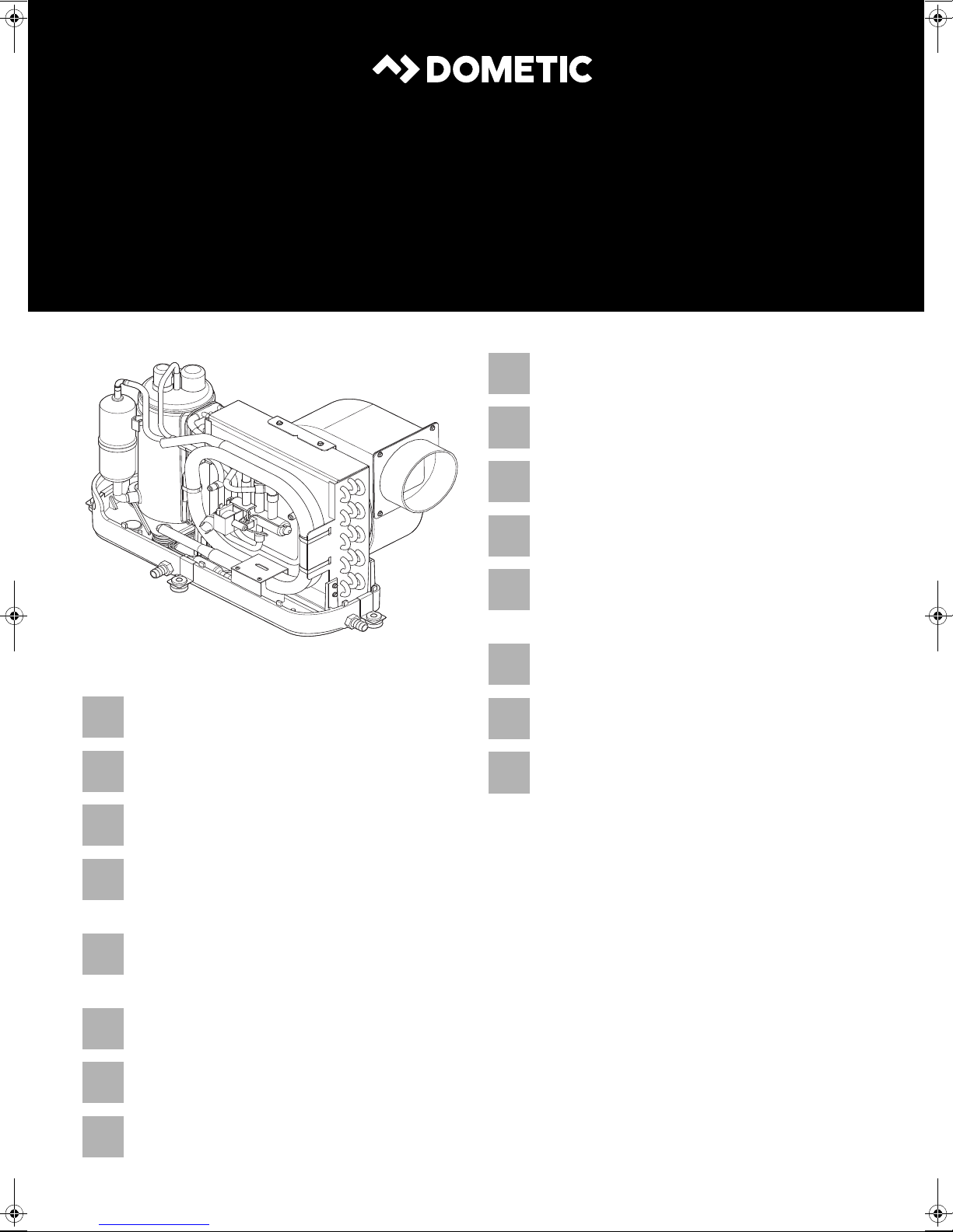
6.1 Components of the Marine Climate System MCS T
Item in
fig. 1, page 3
1Duct ring
2Mounting bracket
3 Condensate drain (two of three locations shown)
4 Composite base pan
5 Rotary compressor
6 Rotable blower assembly
Description
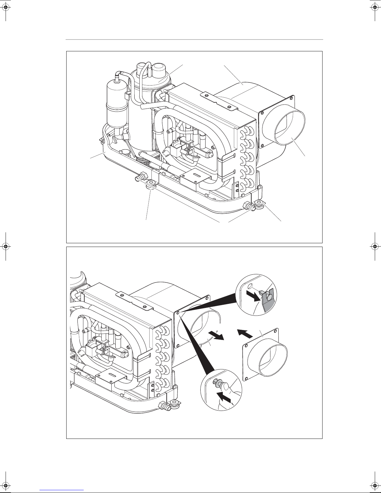
MCS T16 only:
The DTU unit T16 is supplied with a 7" duct ring.
➤ Replace the 7" duct ring with the 6" duct ring using the 4 rivets supplied
(fig. 2, page 3).
16
Page 17

EN
MCS T6, MCS T12, MCS T16 Unpacking and inspection of the scope of delivery
7 Unpacking and inspection of the scope of
delivery
➤ Check all items against the packing list to ensure all cartons have been
received.
➤ Move units in the normal “up” orientation as indicated by the arrows on each
carton.
➤ Examine cartons for shipping damage, removing the units from the cartons if
necessary.
➤ If the unit is damaged, the carrier should make the proper notation on the
delivery receipt acknowledging the damage.
8 Installation
CAUTION! Danger of injury
The system may only be installed by qualified personnel from a specialist com-
!
pany. The following information is intended for technicians who are familiar
with the guidelines and safety precautions to be applied.
I
•
Plan all connections which must be made including
– ducting,
– condensate drain,
– seawater in and out,
– electrical power connections,
– location of control,
– seawater pump placement,
to assure easy access for routing and servicing.
NOTE
Review the following notes prior to and after installation.
17
Page 18

EN
Installation MCS T6, MCS T12, MCS T16
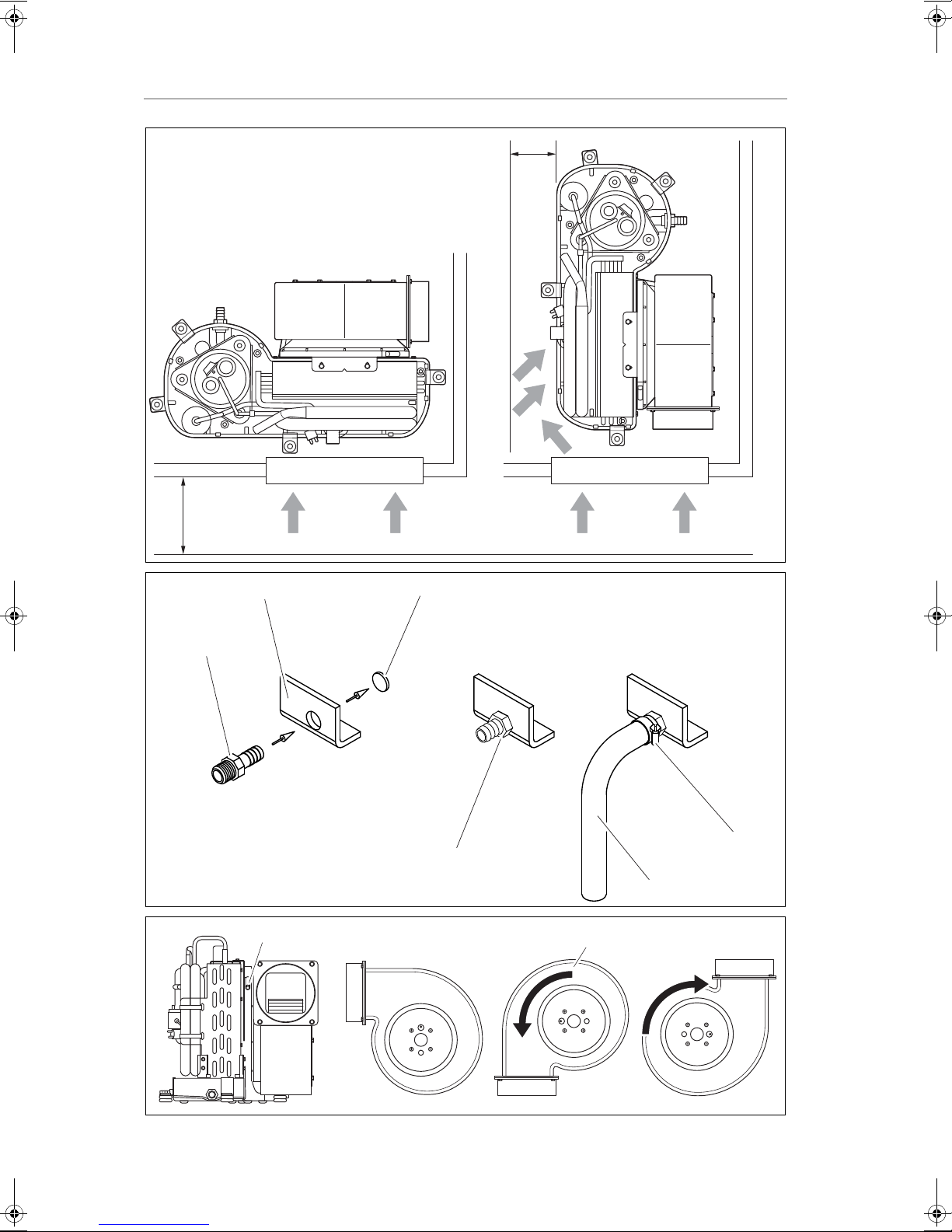
8.1 Spacing Allowances and Unit Dimensions
See fig. 3, page 4:
NOTE
The blower is rotatable by 270 degrees, to ease installation and improve air
I
flow.
Space allowances (fig. 3, page 4)
The following space allowances should be considered when mounting the unit:
•
Allow a minimum of 152 mm clearance around the unit in the area of the seawater and condensate drain piping.
•
Allow a minimum of 76 mm of air space in front of the evaporator coil for the
return-air intake if it is adjacent to a bulkhead.
•
For flexible ducting connection and for clearance needed behind the supplyair grille add the following values to get the total clearance distance:
– 51 mm for the duct ring
– 25 mm for the duct bend radius and
– diameter of the ducting.
•
Allocate enough space for installation and serviceability.
Unit dimensions
Unit Capacity 6 T 12 T 16 T
Minimum duct diameter (mm)
2
Minimum duct area (cm
Minimum distance return grill (cm
Minimum distance supply grill (cm
)
2
)
2
)
102 152 152
81 183 183
413 839 1032
206 452 516
18
Page 19

EN
MCS T6, MCS T12, MCS T16 Installation
8.2 Condensate Drains
WARNING!
Do not terminate condensate drain line
!
– within 1 m of any outlet of engine or generator exhaust systems,
– in a compartment housing of an engine or generator,
– in a bilge, unless the drain is connected properly to a sealed
condensate or shower sump pump.
Failure to comply may allow bilge or engine room vapors to mix with the air
conditioners return-air and contaminate living areas which may result in injury
or death.
Mind the following notes on the installation of the condensate drains:
•
Do not route condensate drains to the bilge.
•
Run the condensate drain line downward from the unit to a suitable drain
location.
•
The condensate drain line should have a trap.
I
For installation of the condensate drain (fig. 4, page 4):
➤ Remove the aft facing watertight plug (3) from the base pan (2) of the air
conditioning unit using the hose barb (1).
➤ Screw the hose barb into the drain hole and tighten it (4).
➤ Secure the drain hose with a stainless steel hose clamp (5).
➤ Install the condensate drain hose downhill from the unit and to a safe and
proper collection point (6).
The hose should have a trap.
NOTE
•
Two drain fittings may be used and the hoses teed together provided there
is a minimum 50 mm drop from the bottom of the base pan to the tee
connection.
•
Consideration should be given to installing a trap in the condensate drain
line(s) so that normal discharge of condensate can fill the trap and prevent
the ingress of carbon monoxide (CO) or other potentially harmful vapors.
➤ Test the installation by pouring one liter of water into the base pan and check-
ing for good flow.
19
Page 20

EN
Installation MCS T6, MCS T12, MCS T16
8.3 Blower Assembly
Rotate the blower to allow the most direct flow of air to the supply-air grille
(fig. 5, page 4).
➤ Loosen the adjustment screw (1).
➤ Rotate the blower (2).
➤ Tighten the adjustment screw (1).
8.4 Electrical Box
Mind the following notes on the installation of the electrical box (fig. 8 3,
page 6):
•
Mount the electrical box in a dry location.
•
Mount the electrical box to a flat, solid surface within 1 m of the unit.
•
Mount the electrical box within 4.5 m of the location where the digital control will be installed.
➤ Use the 4 mounting slots in the back of the electric box to attach it to a suita-
ble mounting surface.
➤ Use screws appropriate for mounting surface (not included).
8.5 Supply-Air Grille
Mind the following notes on the installation of the supply-air grille to ensure
direct uninterrupted airflow from the blower:
NOTICE!
In no instance should the supply-air grille discharge be directed towards the
A
return-air grille, as this will cause the system to short cycle.
•
Install the supply-air grille as high as possible.
•
A minimum clearance of 76 mm plus the duct diameter size is required
behind the supply-air grille for attaching the ducting.
➤ Create the cut outs for the supply-air grille according to the following table:
MCS T6 MCS T12 MCS T16
4.9" x 4.9"
125 x 125 mm
➤ Mount the supply-air grille.
20
9.9" x 5.9"
252 x 150 mm
9.9" x 7.9"
252 x 201 mm
Page 21

EN
MCS T6, MCS T12, MCS T16 Installation
8.6 Return-air Grille
Mind the following notes on the installation of the return-air grille to ensure direct
uninterrupted airflow to the evaporator:
•
Install the return-air grille as low and as close to the unit as possible.
•
Install the return-air grille away from exhaust and bilge vapors.
•
The return-air grille should have a minimum of 107 mm of clearance in front of
it in the cabin area (fig. 3, page 4).
➤ Create the cut out for the return-air grilles according to the following table:
MCS T6 MCS T12 MCS T16
9.9" x 7.9"
252 x 201 mm
➤ If your kit is supplied with a filtered return-air grille: Remove the filter attached
to the unit’s evaporator and discard it.
Two filters are not better than one, as the reduced air flow will decrease per-
formance and possibly freeze the evaporator coil.
➤ Mount the return-air grille.
8.7 Ducting
Mind the following notes on the installation of the ducting:
•
The ducting should be run as straight, smooth and taut as possible.
•
Avoid any unnecessary bends and loops. Rotate the blower instead.
•
Minimize the number of 90° bends (two tight 90° bends can reduce airflow
by 25 %).
•
Ensure the ducting is properly connected with no excess.
Proceed as follows to install the ducting:
13.9" x 9.9"
353 x 252 mm
13.9" x 9.9"
353 x 252 mm
➤ Start at either end (the air-discharge grille or the air conditioning unit).
➤ Pull back the fiberglass insulation exposing the inner mylar duct hose.
➤ Slide the inner mylar duct hose around the mount ring until it bottoms out.
➤ Screw 3 or 4 stainless steel sheet metal screws through the duct hose into the
transition ring.
Make sure to catch the wire in the duct hose with the heads of the screws.
Do not use band clamps, as the hose will slide off.
➤ Wrap duct tape around the ducting and ring joint to prevent any air leaks.
➤ Pull the insulation back up over the mylar to the ring and tape this joint.
21
Page 22

EN
Installation MCS T6, MCS T12, MCS T16
➤ Run the ducting to the other end, keeping it as straight, smooth, and taut as
possible.
➤ Remove excess ducting.
➤ Use the same connection method at the other end.
8.8 Control Panel Installation
Mind the following notes on the installation of the control panel (fig. 8 2,
page 6):
•
Mount the control panel (2) within 4.5 m of the electrical box (3).
•
Mount the control panel on an inside wall, slightly higher than mid-height of
the cabin, in a location with freely circulating air where it can best sense average temperature.
•
Do not mount the control panel
– in direct sunlight,
– near any heat producing appliances
– in a bulkhead where temperatures radiating from behind the panel may
affect performance
– in the supply-air stream
– above or below a supply or return-air grille
Before mounting the control panel, consider the location:
➤ Create a cut out size for the control panel:
64 mm (width) x 48 mm (height).
➤ Plug one end of the display cable (8-pin RJ-45 connector) into the display
socket J1 (fig. 0 4, page 8) of the electric box and the other end into the
back of the control panel.
➤ Remove jumper JP5 (fig. 0 14, page 8) of the electric box to activate
display.
➤ Prior to placement clean the mounting surface with isopropyl alcohol only
(test alcohol on hidden portion of surface first).
➤ Secure the control panel to a bulkhead with the adhesive strips provided.
22
Page 23

EN
MCS T6, MCS T12, MCS T16 Installation
8.9 Remote Air Sensor Installation (optional)
Install the optional remote air sensor if the display cannot be mounted in a proper
location for accurately sensing room temperature. Installing the remote sensor
overrides the display‘s built-in sensor. The standard cable length for the remote
air sensor is 5 ft (1.5 m).
➤ Mount the remote air sensor (fig. 8 4, page 6) in the plastic clip mounted
on the return air side of the evaporator.
➤ Plug the cable (6-pin connector) into the ALT AIR socket (J3)of the circuit
board (fig. 0 5, page 8).
23
Page 24

EN
Installation MCS T6, MCS T12, MCS T16
8.10 Unit and Seawater System Installation
8.10.1 Notes on Seawater System Installation
NOTICE!
If the sea water screen filter is not installed, the pump can be damaged.
A
NOTE
If the sea water screen filter is not installed, the warranty for the pump will be
I
void.
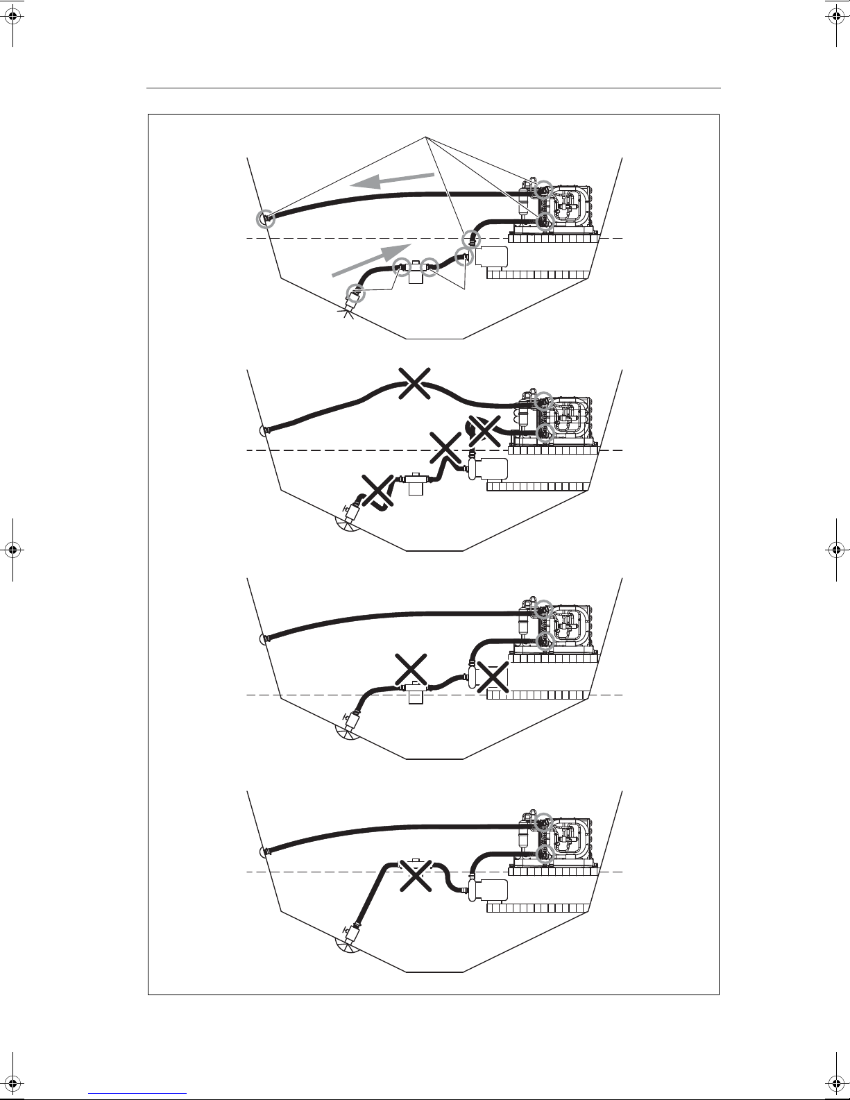
Key to fig. 6, page 5
Item Description
1 Scoop type thru-hull inlet
2 Ball valve
3Strainer
4Seawater pump
5DTU unit
6 Overboard discharge
7 Water line
8Inlet flow
9Outlet flow
10 Hose clamps, installed in pairs with adjustment ends on opposite
sides
– A: Correct
Steady upward flow from inlet to unit (8), then downward to outlet (9),
hoses double clamped (10).
– B: Incorrect
Hoses must not have kinks, loops or high spots where air can be trapped.
– C: Incorrect
Pump (4) and strainer (3) must be below water line (7).
– D: Incorrect
Strainer (3) must be below pump (4) and below waterline (7).
Mind the following notes on the installation of the seawater system:
•
The seawater pump must be mounted so that it is always at least 300 mm
below the water line.
•
The seawater pump may be mounted horizontally or vertically, however the
discharge must always be above the inlet (fig. 7, page 6).
•
Ensure the water is flowing freely from overboard discharge while the pump
is running.
24
Page 25

EN
MCS T6, MCS T12, MCS T16 Installation
•
The speed scoop intake must face forward and not be shared with any other
pump.
•
The speed scoop and the shut off valve must be tight and properly sealed.
•
A seawater strainer (3) is mandatory between the shut off valve (seacock) (1)
and the pump (4) to protect the pump from any foreign matter.
•
Ensure access to the filter of the strainer (3).
•
The seawater system should be installed
– with an upward incline from the speed scoop and seacock (1),
– through the strainer (3),
– to the inlet of the pump (4) and
– then up to the inlet of the air conditioning unit’s condenser coil (5).
•
The discharge from the air conditioning unit (5) should run to the seawater
outlet thru-hull fitting (6) which should be located where it can be visually
checked for water flow and as close as practicable to the waterline to reduce
noise.
•
Ensure the hose runs uphill from speed scoop to strainer (3), pump (4) and air
conditioning unit (5).
!
•
Avoid loops, high spots or the use of 90° elbows with seawater hose.
•
The air conditioning unit (5) should be installed as low as possible, but never
in the bilge or engine room areas (such as under a V-berth, dinette seat or
bottom of a locker).
•
Ensure proper spacing around unit.
•
Ensure that the selected location is sealed from direct access to bilge and/or
engine room vapors.
•
Mount the unit (5) on a firm, level, horizontal surface.
•
Double clamp all hose connections with stainless steel clamps, reversing the
clamps.
•
Secure all threaded connections with threaded-sealing tape. Wrap it only
2 to 3 times around it.
•
Tighten one and a half turns beyond hand tight.
WARNING!
•
Do not tighten the threaded connections too firmly. Otherwise cracks may
form within hours or days.
•
Before you start up the boat, check for any leaks. If you are unsure of how to
proceed, contact a qualified ship's mechanic. Otherwise there is a danger
of the boat sinking. This can result in injury or death.
25
Page 26

EN
Installation MCS T6, MCS T12, MCS T16
8.10.2 Duct Kit Installation
NOTE
•
Unit shown with blower rotated to vertical position.
I
•
Dimensions and part numbers see chapter “Scope of Delivery” on page 12.
Key to fig. 8, page 6
Item Description
1 Supply air grille and transition box
2 Digital display
3Electric box
4 Remote air sensor (optional)
5Seawater outlet hose
6 Overboard discharge
7Seawater inlet hose
8 Seawater scoop thru-hull inlet
9 Seacock shut-off valve
10 Seawater strainer
11 Seawater pump
12 Condensate drain
13 Mounting bracket
14 A/C unit
15 Return air grille and filter
16 Insulated flexible ducting
26
Page 27

EN
MCS T6, MCS T12, MCS T16 Installation
8.10.3 Seawater Kit Installation
Key to fig. 9, page 7
Item Description
1Water line
2 Overboard discharge thru-hull
3Seawater hose
4DTU unit
5 Electrical box
6 Seawater pump electrical cable
7Seawater pump
8 PVC adapter, 1/2" FPT x 1/2" HB
9 PVC adapter, 1/2" MPT x 1/2" HB
10 Strainer
11 Seawater intake (see Detail A)
Seawater Intake (Detail A)
Item in A Description
12 Seawater house
13 Hose clamps, reversed
14 PVC adapter, 1/2" MPT x 1/2" HB
15 Ball valve
16 Nut
17 Backing plate (not included in kit)
18 Bedding compound (not included in kit)
19 Hull
20 Speed scoop
27
Page 28

EN
Installation MCS T6, MCS T12, MCS T16
8.10.4 Installation of the Seawater System
➤ Install the seawater speed scoop intake as far below the water line and as
close to the keel as possible and with intake facing forward.
This keeps the intake in the water when the boat heels over so that air does
not get into the system.
➤ Bed the scoop with a marine sealant designed for underwater use.
➤ Apply the bedding compound liberally to both sides and throughout the
hole.
➤ Install the bronze, full flow seacock on the speed scoop thru-hull inlet.
➤ Install the seawater strainer below the level of the pump with access to filter.
➤ Connect the seacock and strainer with an uphill run using the 5/8" (16 mm)
reinforced marine grade hose.
➤ Mount the seawater pump securely above the strainer, at least 300 mm
below the water line.
➤ Mount the air conditioning unit by securing the base pan onto a flat, horizon-
tal surface with the mounting clip brackets and the 4 screws.
The base pan also serves as a condensate pan.
➤ Connect the discharge from the pump uphill to the bottom inlet of the air
conditioning unit’s condenser coil with 5/8 (16 mm) reinforced marine grade
hose.
➤ Install the overboard discharge thru-hull fitting.
➤ Connect the discharge from the condenser coil to the overboard discharge
thru-hull fitting with 5/8" (16 mm) reinforced marine grade hose.
➤ Connect all metallic parts in contact with seawater to the vessel’s bonding
system including
– the speed scoop inlet,
– pump (the harness ground wire),
– the air conditioner.
28
Page 29

EN
MCS T6, MCS T12, MCS T16 Connecting the Marine Climate System MCS T
9 Connecting the Marine Climate System
MCS T
WARNING!
Turn off AC power supply circuit breaker before opening electrical box and
!
accessing the terminal strip.
NOTE
Failure to properly ground and bond the system will void the warranty!
I
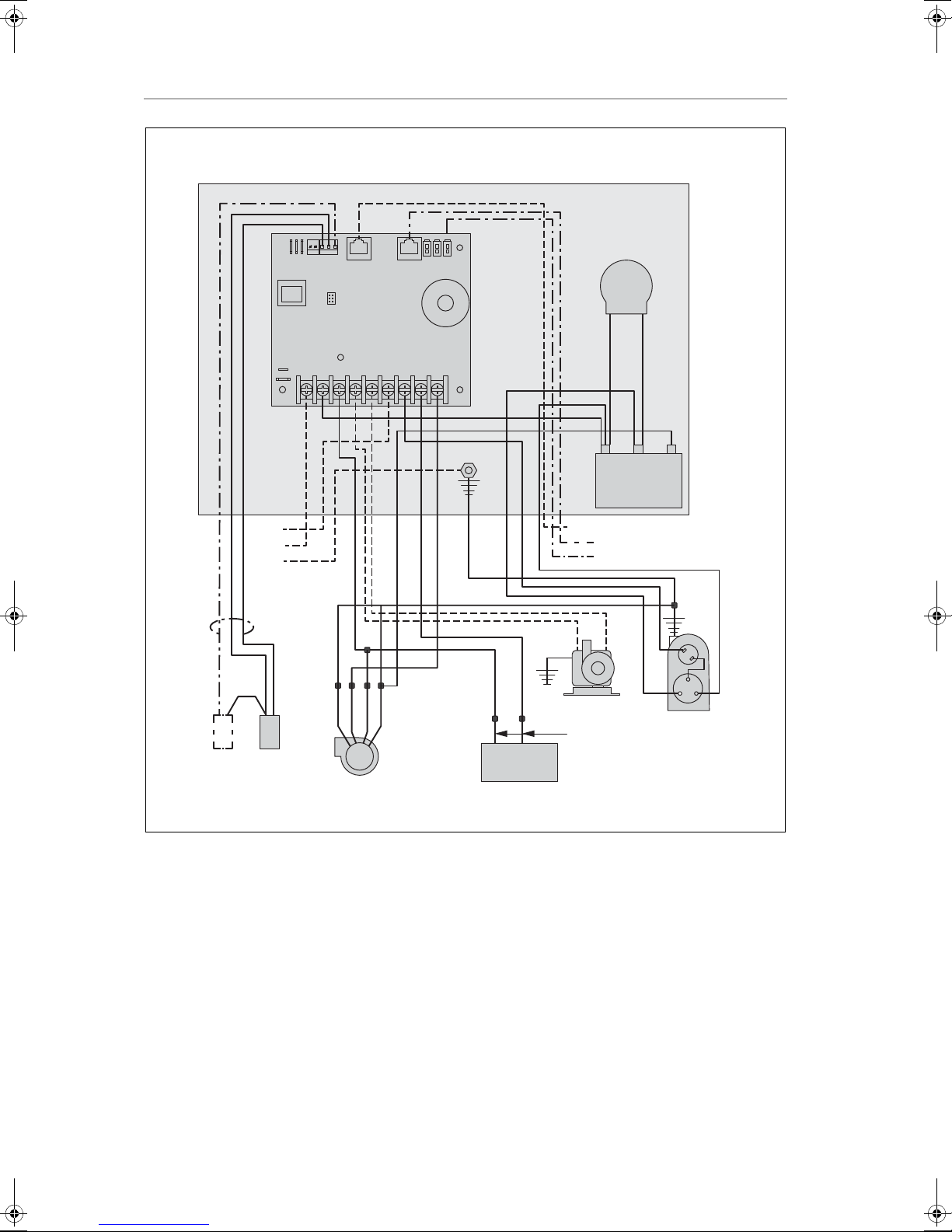
Key to the wiring diagram (fig. 0, page 8):
Item Description
1 Electrical box
2 Positive Temperature Coefficient Resistor (PTCR) start assistant
(MSC T16 only)
3 Run capacitor
4 8-Pin display cable
5 Alternative air sensor (optional)
6 Outside air sensor (not used)
7Compressor
8 Pump or pump relay panel
9 Reversing valve
10 Fan
11 High pressure switch
12 Low pressure switch (not used)
13 Power supply
The following guidelines should be followed during the connection of the
Marine Climate System:
•
The correct size circuit breaker should be used to protect the system as specified on the air conditioning unit’s data plate label.
•
Install and ground/bond AC power source in accordance with marine electrical standards.
•
Use a minimum of 3.5 mm² boat cable
– to supply power to the air conditioning unit
– to supply power to the seawater pump
– to extend the wires on the pump
•
Any electrical connections in the bilge below the waterline should use sealing heat shrink type butt splices.
29
Page 30

EN
Operation MCS T6, MCS T12, MCS T16
•
All connections to the terminal strip shall be made with appropriately sized
ring terminals (not supplied).
•
Each air conditioning unit installed requires its own dedicated circuit breaker.
– If there is only one air conditioning unit installed, the seawater pump
does not require a circuit breaker; the wiring from the seawater pump is
connected to the terminal strip on the unit (see wiring diagram, fig. 0,
page 8)
➤ Connect the air conditioning unit to the boat's bonding system to prevent
corrosion due to stray electrical current.
➤ Ensure that the AC ground of the air conditioning unit is properly connected
to the AC ground of the boat.
➤ Within the boat itself, ensure that the AC ground bus is connected to the DC
ground bus at exactly one place.
➤ Bond individually all pumps, metallic valves and fittings in the seawater circuit
that are insulated from the air conditioning unit by PVC or rubber hoses to the
boat's bonding system.
This will help eliminate any possibility of corrosion due to stray current.
10 Operation
NOTE
For operation see the Operating Manual.
I
11 Programming
NOTE
For programming and defining the parameters see the Operating Manual.
I
12 Troubleshooting Guidelines
NOTE
For troubleshooting see the Operating Manual.
I
30
Page 31

EN
MCS T6, MCS T12, MCS T16 Warranty
13 Warranty
The statutory warranty period applies. If the product is defective, please contact
the service partner in your country (addresses on the back on the instruction manual).
Our experts will be happy to help you and will discuss the warranty process with
you in more detail.
14 Disposal
➤ Place the packaging material in the appropriate recycling waste bins
wherever possible.
If you wish to finally dispose of the product, ask your local recycling centre or
specialist dealer for details about how to do this in accordance with the appli-
M
cable disposal regulations.
31
Page 32

EN
Technical Data MCS T6, MCS T12, MCS T16
15 Technical Data
15.1 Unit Data
Marine Climate
System
MCS T6
Cooling capacity: 6000 BTU/h
1758 W
Input Voltage: 230 V 230 V 230 V
Current consumption
Cooling:
Heating: 4.7 A 5.3 A 6.9 A
Refrigerant: R-410A R-410A R-410A
Refrigerant quantity: 8.5 oz/241 g 10.5 oz/298 g 12.5 oz/354 g
CO
equivalent: 0.503 t 0.622 t 0.739 t
2
Global warming potential
(GWP):
Dimensions (WxHxD):
Unit:
Control panel: 81 x 64 x 24 mm 81 x 64 x 24 mm 81 x 64 x 24 mm
Panel cutout: 64 x 48 mm 64 x 48 mm 64 x 48 mm
Weight (unit only): 19.3 kg 23.6 kg 26.5 kg
3.7 A 4.3 A 5.5 A
2088 2088 2088
448 x 282 x
272 mm
Marine Climate
System
MCS T12
12000 BTU/h
3517 W
519 x 318 x
315 mm
Marine Climate
System
MCS T16
16000 BTU/h
4689 W
544 x 341 x
338 mm
Contains fluorinated greenhouse gases
Hermetically sealed equipment
15.2 Cable Lengths
Display Cable: 4.5 m Standard
Alternate Air Sensor: 2.0 m Standard
All custom cable lengths supplied in
standard 1.5 m increments:
NOTE
Maximum length of display and sensor cables is 22.9 m.
I
32
22.5 m Maximum
Page 33

DE
MCS T6, MCS T12, MCS T16 Erklärung der Symbole
Bitte lesen Sie diese Anleitung vor der Inbetriebnahme sorgfältig
durch und bewahren Sie sie auf. Geben Sie sie im Falle einer Weitergabe der Anlage an den Nutzer weiter.
Inhalt
1 Erklärung der Symbole . . . . . . . . . . . . . . . . . . . . . . . . . . . . . . . . . 33
2 Sicherheitshinweise . . . . . . . . . . . . . . . . . . . . . . . . . . . . . . . . . . . . 34
3 Zielgruppe. . . . . . . . . . . . . . . . . . . . . . . . . . . . . . . . . . . . . . . . . . . . 35
4 Lieferumfang. . . . . . . . . . . . . . . . . . . . . . . . . . . . . . . . . . . . . . . . . . 36
5 Bestimmungsgemäßer Gebrauch . . . . . . . . . . . . . . . . . . . . . . . . 39
6 Technische Beschreibung . . . . . . . . . . . . . . . . . . . . . . . . . . . . . . . 39
7 Lieferumfang entpacken und prüfen . . . . . . . . . . . . . . . . . . . . . . 40
8 Installation. . . . . . . . . . . . . . . . . . . . . . . . . . . . . . . . . . . . . . . . . . . . 41
9 Anschluss der Bootsklimaanlage MCS T . . . . . . . . . . . . . . . . . . . 52
10 Betrieb . . . . . . . . . . . . . . . . . . . . . . . . . . . . . . . . . . . . . . . . . . . . . . . 53
11 Programmieren. . . . . . . . . . . . . . . . . . . . . . . . . . . . . . . . . . . . . . . . 53
12 Richtlinien zur Fehlerbeseitigung. . . . . . . . . . . . . . . . . . . . . . . . . 53
13 Garantie. . . . . . . . . . . . . . . . . . . . . . . . . . . . . . . . . . . . . . . . . . . . . . 54
14 Entsorgung . . . . . . . . . . . . . . . . . . . . . . . . . . . . . . . . . . . . . . . . . . . 54
15 Technische Daten . . . . . . . . . . . . . . . . . . . . . . . . . . . . . . . . . . . . . . 55
1 Erklärung der Symbole
WARNUNG!
Sicherheitshinweis: Nichtbeachtung kann zu Tod oder schwerer Verletzung
!
führen.
VORSICHT!
Sicherheitshinweis: Nichtbeachtung kann zu Verletzungen führen.
!
ACHTUNG!
Nichtbeachtung kann zu Materialschäden führen und die Funktion des
A
Produktes beeinträchtigen.
33
Page 34

DE
Sicherheitshinweise MCS T6, MCS T12, MCS T16
HINWEIS
Ergänzende Informationen zur Bedienung des Produktes.
I
2 Sicherheitshinweise
Der Hersteller übernimmt in folgenden Fällen keine Haftung für Schäden:
•
Montage- oder Anschlussfehler
•
Beschädigungen am Produkt durch mechanische Einflüsse und Überspannungen
•
Veränderungen am Produkt ohne ausdrückliche Genehmigung vom
Hersteller
•
Verwendung für andere als die in der Anleitung beschriebenen Zwecke
2.1 Grundlegende Sicherheit
WARNUNG!
•
Achtung Lebensgefahr!
!
In der Anlage befinden sich Bauteile, an denen eine Wechselspannung von
230 V~ anliegt.
•
Es besteht die Gefahr von elektrischen Schlägen!
Bevor Sie eine der Abdeckungen öffnen, trennen Sie die Spannung an der
Hauptschalttafel oder an der Stromquelle.
Andernfalls besteht die Gefahr von Personenschäden oder Verletzungen mit
Todesfolge.
•
Um die Gefahr von elektrischen Schlägen und Personenschäden auf ein Minimum zu beschränken, muss diese Komponente effektiv geerdet werden.
•
Diese Anlage erfüllt nicht die Anforderungen an den Explosionsschutz. Installieren Sie die Anlage nicht in Räumen für mit Benzin angetriebenen Motoren,
Tanks, LPG/CPG-Zylindern, Reglern, Ventilen oder Anschlüssen für Kraftstoffleitungen.
Andernfalls besteht die Gefahr von Personenschäden oder Verletzungen mit
Todesfolge.
•
Schließen Sie die Kondensatablaufleitung nicht
– innerhalb von 1 m im Umkreis von Motorausgängen oder Generator-
Auspuffanlagen,
– in einem Fach eines Motors oder Generators,
– in einer Bilge ab, es sei denn, der Ablauf ist ordnungsgemäß mit einer
abgedichteten Kondensatpumpe oder Pumpenanlage für den Sammel-
brunnen der Dusche verbunden.
34
Page 35

DE
MCS T6, MCS T12, MCS T16 Zielgruppe
Andernfalls können sich Dämpfe aus der Bilge oder dem Maschinenraum
mit der Abluft der Klimaanlage vermischen und die Wohnbereiche kontaminieren. Es besteht die Gefahr von Personenschäden oder Verletzungen mit
Todesfolge.
•
Um das Eindringen von Kohlenmonoxyd (CO) oder anderen schädlichen
Gasen zu verhindern, sollte ein Abscheider in der oder den Kondensatablaufleitungen installiert werden.
•
Installation und Wartung dieser Anlage kann wegen des Systemdrucks und
der elektrischen Bauteile gefährlich sein.
•
Installieren Sie die Klimaanlage nicht in der Bilge oder im Maschinenraum.
•
Sorgen Sie dafür, dass sich ein Feuerlöscher in der Nähe des Arbeitsbereichs
befindet.
VORSICHT!
•
Tragen Sie eine Schutzbrille und Arbeitshandschuhe.
!
ACHTUNG!
•
Befestigen Sie das Klimagerät an einer festen ebenen Plattform mit den vier
A
Montagebügeln aus dem Lieferumfang.
2.2 Sicherer Umgang mit elektrischen Leitungen
VORSICHT!
•
Befestigen und verlegen Sie Leitungen so, dass keine Stolpergefahr entsteht
!
A
und eine Beschädigung des Kabels ausgeschlossen ist.
ACHTUNG!
•
Müssen Leitungen durch scharfkantige Wände oder Schotte geführt werden,
so verwenden Sie Leerrohre bzw. Leitungsdurchführungen!
•
Verlegen Sie keine losen oder scharf abgeknickten Leitungen an elektrisch
leitenden Materialien (Metall)!
•
Ziehen Sie nicht an den Leitungen.
3 Zielgruppe
Diese Anleitung richtet sich an Facharbeiter in Werkstätten, die mit den anzuwendenden Richtlinien und Sicherheitsvorkehrungen vertraut sind.
35
Page 36

DE
Lieferumfang MCS T6, MCS T12, MCS T16
4 Lieferumfang
HINWEIS
Zum Lieferumfang jeder Klimaanlage gehört eine Hakenbaugruppe für den
I
4.1 Bootsklimaanlage MCS T6
Kondensatschlauch und vier Montagebügeln.
MCST6 – Komplettes Kit (Teile-Nr. 9600000549)
Menge Beschreibung
1 DTU6, nur Einheit
1 Bedienfeld
1 Schaltkasten
1 Elektrischer Kabelbaum
Rohrleitungs-Kit
Menge Beschreibung
3,8 m Rohrleitung, isoliert, 100 mm/4" ID
1 Zuluft-Schutzgitter 4"x 4", 102 x 102 mm
1 Abluft-Schutzgitter 10"x 8", 254 x 203 mm, eloxiert
Meerwasser-Kit
Menge Beschreibung
1 Rumpf, 5/8", Kunststoff
7,6 m Meerwasserschlauch, 5/8"
3 PVC-Adapter, 1/2" MPT x 1/2" HB
2 PVC-Adapter, 1/2" FPT x 1/2" HB
1 Siebfilter, 1/2", mit Klammer 1/2" FPT
1 Meerwasserpumpe PML250 (220 Vw, 50/60 Hz)
17 Schlauchklemmen, dünn
1 Kugelventil, 1/2", Bronze
1 Speed-Scoop, 1/2", Bronze
36
Page 37

DE
MCS T6, MCS T12, MCS T16 Lieferumfang
Zubehör
Menge Beschreibung
1 Schlauchhakenbaugruppe
4 Befestigungswinkel
1 Rückluftfilter
4.2 Bootsklimaanlage MCS T12
MCS T12 – Komplettes Kit (Teile-Nr. 9600000550)
Menge Beschreibung
1 DTU12, nur Einheit
1Bedienfeld
1 Schaltkasten
1 Elektrischer Kabelbaum
Rohrleitungs-Kit
Menge Beschreibung
3,8 m Rohrleitung, isoliert, 150 mm/6" ID
1 Zuluft-Schutzgitter 10"x 6", 254 x 153 mm
1 Abluft-Schutzgitter 14"x 10", 356 x 254 mm, eloxiert
Meerwasser-Kit
Menge Beschreibung
1 Rumpf, 5/8", Kunststoff
7,6 m Me er wa ss er sc hl au ch , 5/8 "
3 PVC-Adapter, 1/2" MPT x 1/2" HB
2 PVC-Adapter, 1/2" FPT x 1/2" HB
1 Siebfilter, 1/2", mit Klammer 1/2" FPT
1 Meerwasserpumpe PML250 (220 Vw, 50/60 Hz)
17 Schlauchklemmen, dünn
1 Kugelventil, 1/2", Bronze
1 Speed-Scoop, 1/2", Bronze
37
Page 38

DE
Lieferumfang MCS T6, MCS T12, MCS T16
Ersatzteile
Menge Beschreibung
1 Schlauchhakenbaugruppe
4 Befestigungswinkel
1Rückluftfilter
4.3 Bootsklimaanlage MCS T16
MCS T16 – Komplettes Kit (Teile-Nr. 9600000551)
Menge Beschreibung
1 DTU16, nur Einheit
1 Bedienfeld
1 Schaltkasten
1 Elektrischer Kabelbaum
Rohrleitungs-Kit
Menge Beschreibung
3,8 m Rohrleitung, isoliert, 150 mm/6" ID
1 Zuluft-Schutzgitter 10"x 8", 254 x 203 mm
1 Abluft-Schutzgitter 14"x 10", 356 x 254 mm
1 Befestigungsring 6"
4Kunststoffniete
Meerwasser-Kit
Menge Beschreibung
1 Rumpf, 5/8", Kunststoff
7,6 m Meerwasserschlauch, 5/8"
3 PVC-Adapter, 1/2" MPT x 1/2" HB
2 PVC-Adapter, 1/2" FPT x 1/2" HB
1 Siebfilter, 1/2", mit Klammer 1/2" FPT
1 Meerwasserpumpe PML500 (220–240 Vw,
50/60 Hz)
17 Schlauchklemmen, dünn
1 Kugelventil, 1/2", Bronze
1 Speed-Scoop, 1/2", Bronze
38
Page 39

DE
MCS T6, MCS T12, MCS T16 Bestimmungsgemäßer Gebrauch
Ersatzteile
Menge Beschreibung
1 Schlauchhakenbaugruppe
4 Befestigungswinkel
1 Rückluftfilter
5 Bestimmungsgemäßer Gebrauch
Die Bootsklimaanlage MCS T wurde für den Einsatz auf Booten und Yachten
entwickelt. Sie kann die inneren Bereiche des Boots oder der Yacht abkühlen
oder erwärmen.
6 Technische Beschreibung
Die Bootsklimaanlage Marine Climate System MCS T ist für eine Spannungsversorgung mit 230 Vw vorgesehen.
Der Bausatz der Bootsklimaanlage MCS T besteht aus folgenden Bauteilen:
•
DTU-Einheit
•
Bedienfeld
•
Rohrleitungen
•
Zuluft-Schutzgitter
•
Abluft-Schutzgitter
•
Meerwasserpumpe
•
Siebfilter
•
Rumpf-Speed-Scoop
•
Außenbordanschluss
•
Meerwasserschlauch
•
Armaturen für Pumpe und Filtersieb
Es handelt sich um eine meerwassergekühlte Klimaanlage.
39
Page 40

DE
Lieferumfang entpacken und prüfen MCS T6, MCS T12, MCS T16
6.1 Bauteile der Bootsklimaanlage MCS T
Position in
Abb. 1,
Seite 3
1Rohrleitungsring
2 Befestigungswinkel
3 Kondensatablauf (angezeigt werden zwei von drei Positionen)
4 Zusammengesetzte Basiswanne
5 Rotationskompressor
6 Drehbare Gebläsebaugruppe
Nur MCS T16:
Die Einheit T16 wird mit einem 7" Rohrleitungsring geliefert.
➤ Ersetzen Sie den 7" Rohrleitungsring durch den mitgelieferten
6" Rohrleitungsring und verwenden Sie die 4 mitgelieferten Kunststoffnieten
(Abb. 2, Seite 3).
Beschreibung
7 Lieferumfang entpacken und prüfen
➤ Überprüfen Sie alle Teile anhand der Verpackungsliste, um sicherzustellen,
dass alle Kartons in der Lieferung enthalten sind.
➤ Stellen Sie die Teile in der normalen aufrechten Position hin, die durch die
Pfeile auf jedem Karton angegeben wird.
➤ Untersuchen Sie, ob die Kartons Versandschäden aufweisen und entnehmen
Sie die Teile ggf. aus den Kartons.
➤ Wenn ein Teil Beschädigungen aufweist, sollte die Spedition die Beschädi-
gung durch einen entsprechenden Vermerk auf dem Lieferschein quittieren.
40
Page 41

DE
MCS T6, MCS T12, MCS T16 Installation
8 Installation
VORSICHT! Verletzungsgefahr!
Die Installation der Anlage darf ausschließlich nur von entsprechend geschul-
!
ten Fachbetrieben durchgeführt werden. Die nachfolgenden Informationen
richten sich an Fachkräfte, die mit den anzuwendenden Richtlinien und
Sicherheitsvorkehrungen vertraut sind.
•
Planen Sie alle durchzuführenden Verbindungen, inkl.:
– Rohrleitungen,
– Kondensatablauf,
– Meerwasserein- und -ausgänge,
– Stromanschlüsse,
– Lage der Steuerung,
– Platzierung der Meerwasserpumpe,
um den einfachen Zugang für die Verlegung der Leitungen und Wartung
sicherzustellen.
HINWEIS
Lesen Sie die folgenden Hinweise vor und nach der Installation.
I
8.1 Erforderlicher Platzbedarf und Geräteabmessungen
Siehe Abb. 3, Seite 4
HINWEIS
Das Gebläse ist um 270 Grad drehbar, um die Installation zu vereinfachen und
I
einen besseren Luftstrom zu ermöglichen.
Erforderlicher Platz (Abb. 3, Seite 4)
Bei der Gerätemontage sollten die folgenden Platzanforderungen berücksichtigt werden:
•
Berücksichtigen Sie um die Anlage im Bereich der Ablaufrohre für Meerwasser und Kondensat einen Freiraum von 152 mm.
•
Berücksichtigen Sie bei einer Montage in der Nähe des Schotts für den
Ablufteinlass vor der Verdampferspule einen Mindestabstand von 76 mm.
•
Um flexible Rohranschlüsse und den erforderlichen Abstand hinter dem
Zuluft-Schutzgitter zu gewährleisten, addieren Sie die folgenden Werte, um
den erforderlichen Gesamtabstand zu ermitteln:
– 51 mm für den Rohrleitungsring,
– 25 mm für den Biegeradius der Rohrleitungen und
– Durchmesser der Rohrleitungen.
•
Achten Sie darauf, dass der Platz für Montage- und Wartungsarbeiten ausreicht.
41
Page 42

DE
Installation MCS T6, MCS T12, MCS T16
Geräteabmessungen
Geräteabmessung 6 T 12 T 16 T
Mindestmaß Leitungsdurchmesser (mm)
Mindestmaß Leitungsquerschnitt (cm
Mindestabstand Abluft-Schutzgitter (cm
Mindestabstand Zuluft-Schutzgitter (cm
8.2 Kondensatabläufe
WARNUNG!
Lassen Sie die Kondensatablaufleitung nicht enden:
!
– innerhalb von 1 m im Umkreis von Motorausgängen oder Generator-
Auspuffanlagen,
– in einem Gehäuse eines Motors oder Generators,
– in einer Bilge, es sei denn, der Ablauf ist ordnungsgemäß mit einer
abgedichteten Kondensatpumpe oder Pumpenanlage für den Sammel-
brunnen der Dusche verbunden.
Andernfalls können Dämpfe aus der Bilge oder dem Maschinenraum sich mit
der Abluft der Klimaanlage vermischen und die Wohnbereiche kontaminieren.
Es besteht die Gefahr von Tod oder schwerer Verletzung.
102 152 152
2
)
2
)
2
)
81 183 183
413 839 1032
206 452 516
Beachten Sie folgende Hinweise bei der Installation der Kondensatabläufe:
•
Führen Sie die Kondensatabläufe nicht zur Bilge.
•
Führen Sie die Kondensatablaufleitung nach unten von der Anlage zu einer
geeigneten Position für den Ablauf.
•
Die Kondensatablaufleitung sollte mit einem Abscheider versehen sein.
Installation des Kondensatablaufs (Abb. 4, Seite 4):
➤ Entfernen Sie mit Hilfe der Schlauchtülle (1) den nach Achtern weisenden
wasserdichten Stopfen (3) von der Basiswanne (2) des Klimageräts.
➤ Drehen Sie die Schlauchtülle in das Loch und ziehen Sie sie fest (4).
➤ Sichern Sie den Kondensatablaufschlauch mit einer Schlauchklemme (5).
➤ Führen Sie den Kondensatablaufschlauch von der Anlage nach unten und an
einen richtlinienkonformen Ort (6).
Der Schlauch sollte mit einem Abscheider versehen sein.
42
Page 43

DE
MCS T6, MCS T12, MCS T16 Installation
HINWEIS
•
Es ist möglich, zwei Ablaufanschlüsse zu verwenden und die Schläuche mit
I
einem T-Anschluss zusammenzuführen, vorausgesetzt, der Abfall von der
Unterkante der Basiswanne zur T-Verbindung beträgt mindestens 50 mm.
•
Ziehen Sie die Installation eines Abscheiders in den Kondensatablaufleitungen in Betracht, so dass der Abscheider durch den normalen
Kondensatabfluss gefüllt wird und Kohlenmonoxyd und andere schädliche
Gase nicht eindringen können.
➤ Testen Sie die Installation, indem Sie einen Liter Wasser in die Basiswanne
gießen und den guten Abfluss überprüfen.
8.3 Gebläsemontage
Drehen Sie das Gebläse, um einen möglichst direkten Luftfluss zum ZuluftSchutzgitter zu gewährleisten (Abb. 5, Seite 4).
➤ Lösen Sie die Einstellschraube (1).
➤ Drehen Sie das Gebläse (2).
➤ Ziehen Sie die Einstellschraube fest (1).
8.4 Schaltkasten
Beachten Sie folgende Hinweise bei der Installation des Schaltkastens
(Abb. 8 3, Seite 6):
•
Montieren Sie den Schaltkasten an eine trockene Position.
•
Montieren Sie den Schaltkasten auf einer ebenen, festen Oberfläche im
Umkreis von 1 m von der Anlage.
•
Montieren Sie den Schaltkasten im Umkreis von 4,5 m von der Position, an
der die digitale Steuerung installiert wird.
➤ Befestigen Sie den Schaltkasten an den 4 Montageöffnungen an der Rück-
seite des Schaltkastens an einer geeigneten Einbaufläche.
➤ Verwenden Sie dabei Schrauben, die für die Einbaufläche geeignet sind
(nicht im Lieferumfang enthalten).
43
Page 44

DE
Installation MCS T6, MCS T12, MCS T16
8.5 Zuluft-Schutzgitter
Beachten Sie folgende Hinweise bei der Installation des Zuluft-Schutzgitters, um
einen direkten, ununterbrochenen Luftfluss zum Gebläse zu gewährleisten:
ACHTUNG!
Unter keinen Umständen darf der Auslass des Zuluft-Schutzgitters zum Abluft-
A
Schutzgitter gerichtet werden, da sonst die Anlage in kurzen Abständen einund ausgeschaltet wird.
•
Installieren Sie das Zuluft-Schutzgitter an einer möglichst hohen Position.
•
Hinter dem Zuluft-Schutzgitter ist ein Mindestabstand von 76 mm plus dem
Rohrdurchmesser erforderlich, um die Rohrleitungen anzuschließen.
➤ Fertigen Sie die Bohrlöcher für das Zuluft-Schutzgitter gemäß der folgenden
Tabelle:
MCS T6 MCS T12 MCS T16
4,9" x 4,9"
125 x 125 mm
➤ Montieren Sie das Zuluft-Schutzgitter.
8.6 Abluft-Schutzgitter
Beachten Sie folgende Hinweise bei der Installation des Abluft-Schutzgitters, um
einen direkten, ununterbrochenen Luftfluss zum Verdampfer zu gewährleisten:
•
Installieren Sie das Abluft-Schutzgitter so tief und so nahe wie möglich an der
Anlage.
•
Installieren Sie das Abluft-Schutzgitter an eine Position, an der es nicht mit
Abgas- und Bilgedämpfen in Kontakt kommen kann.
•
Im Kabinenbereich sollte der Mindestabstand für das Abluft-Schutzgitter
107 mm betragen (Abb. 3, Seite 4).
➤ Fertigen Sie die Bohrlöcher für das Abluft-Schutzgitter gemäß der folgenden
Tabelle:
MCS T6 MCS T12 MCS T16
9,9" x 5,9"
252 x 150 mm
9,9" x 7,9"
252 x 201 mm
9,9" x 7,9"
252 x 201 mm
44
13,9" x 9,9"
353 x 252 mm
13,9" x 9,9"
353 x 252 mm
Page 45

DE
MCS T6, MCS T12, MCS T16 Installation
➤ Wenn zum Lieferumfang des Kits ein Abluft-Schutzgitter mit Filter gehört: Ent-
fernen Sie den Filter, der am Verdampfer der Anlage befestigt ist, und entsorgen Sie diesen.
Zwei Filter sind nicht besser als einer, da der reduzierte Luftfluss die Leistung
vermindert und möglicherweise die Verdampferspule einfriert.
➤ Montieren Sie das Abluft-Schutzgitter.
8.7 Rohrleitungen
Beachten Sie folgende Hinweise bei der Installation der Rohrleitungen:
•
Die Rohrleitungen sollten so gerade, eben und straff wie möglich verlegt
werden.
•
Vermeiden Sie unnötige Biegungen und Schleifen. Drehen Sie stattdessen
das Gebläse.
•
Beschränken Sie die Anzahl der 90°-Biegungen auf ein Minimum (zwei enge
90°-Biegungen können den Luftfluss um 25 % reduzieren).
•
Vergewissern Sie sich, dass die Rohrleitungen ordnungsgemäß ohne Überschuss angeschlossen sind.
Gehen Sie wie folgt vor, um die Rohrleitungsverbindungen herzustellen:
➤ Beginnen Sie an einem Ende (Schutzgitter für den Luftauslass oder Klima-
gerät).
➤ Ziehen Sie die Glasfaserisolierung zurück, um das innere Schlauchrohr aus
Mylar freizulegen.
➤ Schieben Sie das innere Schlauchrohr aus Mylar um den Montagering, bis
der Montagering den Boden berührt.
➤ Schrauben Sie 3 oder 4 Blechschrauben aus Edelstahl durch das
Schlauchrohr in den Übergangsring.
Sorgen Sie dafür, dass der Draht im Schlauchrohr an den Schraubköpfen
befestigt wird.
Verwenden Sie keine Bandverschlüsse, da der Schlauch sonst abrutscht.
➤ Wickeln Sie Klebeband um die Verbindung zwischen Rohrleitung und Ring,
um Luftlecks zu verhindern.
➤ Ziehen Sie die Isolierung wieder über den Mylar-Schlauch zum Ring und
dichten Sie diese Verbindung mit Klebeband ab.
➤ Führen Sie die Rohrleitung zum anderen Ende, achten Sie dabei darauf, dass
diese so gerade, eben und straff wie möglich verlegt wird.
➤ Entfernen Sie überschüssige Rohrleitung.
➤ Verwenden Sie dieselbe Anschlussmethode wie am anderen Ende.
45
Page 46

DE
Installation MCS T6, MCS T12, MCS T16
8.8 Installation des Bedienfelds
Beachten Sie folgende Hinweise bei der bei der Installation des Bedienfelds
(Abb. 8 2, Seite 6):
•
Montieren Sie das Bedienfeld (2) in einem Umkreis von 4,5 m des
Schaltkastens (3).
•
Montieren Sie das Bedienfeld an einer Innenwand, etwas höher als die Mitte
der Kabine an einer Position, an der die Luft frei zirkulieren kann.
•
Montieren Sie das Bedienfeld nicht an Positionen
– mit direkter Sonneneinstrahlung,
– in der Nähe von Wärmequellen,
– in einem Schott, wo hinter dem Bedienfeld Temperaturen abgestrahlt
werden, die die Leistung beeinträchtigen könnten,
– im Zuluftstrom,
– über oder unter einem Zuluft- oder Abluft-Schutzgitter.
Bereiten Sie vor der Montage des Bedienfelds die Einbauposition wie folgt vor:
➤ Fertigen Sie eine Aussparung für die Montage des Bedienfelds:
64 mm (Breite) x 48 mm (Höhe).
➤ Verbinden Sie das eine Ende des Displaykabels (8-poliger RJ-45-Anschluss)
mit der Displaybuchse J1 (Abb. 0 4, Seite 8) im Schaltkasten und das
andere Ende mit der Rückseite des Bedienfelds.
➤ Entfernen Sie den Jumper JP5 im Schaltkasten, um das Display zu aktivieren
(Abb. 0 14, Seite 8).
➤ Reinigen Sie vor der Platzierung die Einbaufläche nur mit Isopropanol (testen
Sie die Lösung vorher an einer unauffälligen Stelle der Oberfläche).
➤ Befestigen Sie das Bedienfeld an einem Schott mit den Klebestreifen aus
dem Lieferumfang.
8.9 Installation des Rückluftsensors (optional)
Wenn am Montageort des Bedienfeld die Raumtemperatur nicht richtig gemessen werden kann, kann ein zusätzlicher Rückluftsensor montiert werden. Der
Rückluftsensor überstimmt die Messwerte des eingebauten Sensors. Das Sensorkabel hat eine Länge von 5 ft (1,5 m).
➤ Befestigen Sie den Rückluftsensor (Abb. 8 4, Seite 6) im Kunstoffclip an der
Rückluftseite des Verdampfers.
➤ Verbinden Sie das Kabel (6-poliger Anschluss) mit der Buchse ALT AIR (J3)
(Abb. 0 5, Seite 8) im Schaltkasten.
46
Page 47

DE
MCS T6, MCS T12, MCS T16 Installation
8.10 Installation der Einheit und der Meerwasseranlage
8.10.1 Hinweise zur Installation der Meerwasseranlage
ACHTUNG!
Wenn der Meerwassersiebfilter nicht installiert wird, kann die Pumpe beschä-
A
I
digt werden!
HINWEIS
Wenn der Meerwassersiebfilter nicht installiert wird, erlischt die Garantie der
Pumpe.
Legende zu Abb. 5, Seite 5:
Pos. Beschreibung
1Scoop-Rumpfeinlass
2Kugelventil
3 Siebfilter
4Meerwasserpumpe
5 DTU-Einheit
6 Überbord-Auslass
7 Wasserlinie
8Einlassfluss
9 Auslassfluss
10 Schlauchklemmen, die paarweise mit den Einstellungsenden an
gegenüberliegenden Seiten installiert werden
– A: Richtig
Stetiger Fluss nach oben vom Einlass zum Gerät (8), dann nach unten zum
Auslass (9), Schläuche zweifach mit Klemmen gesichert (10).
– B: Falsch
Die Schläuche dürfen keine Knicke, Schleifen oder hohe Bereiche aufweisen, in denen sich Luft ansammeln kann.
– C: Falsch
Pumpe (4) und Siebfilter (3) müssen sich unterhalb der Wasserlinie befinden (7).
– D: Falsch
Der Siebfilter (3) muss sich unterhalb der Pumpe (4) und unterhalb der
Wasserlinie (7) befinden.
47
Page 48

DE
Installation MCS T6, MCS T12, MCS T16
Beachten Sie folgende Hinweise bei der bei der Installation der Meerwasseranlage:
•
Die Meerwasserpumpe muss so montiert werden, dass sie sich immer
wenigstens 300 mm unterhalb der Wasserlinie befindet.
•
Die Meerwasserpumpe kann horizontal oder vertikal montiert werden, aber
der Auslass muss sich immer über dem Einlass befinden (Abb. 7, Seite 6).
•
Vergewissern Sie sich, dass das Wasser frei aus dem Außenbord-Auslass
fließt, während die Pumpe läuft.
•
Der Speed-Scoop-Einlass muss nach vorn weisen und darf nicht von einer
anderen Pumpe mitbenutzt werden.
•
Speed-Scoop und Absperrventil müssen dicht und ordnungsgemäß abgedichtet werden.
•
Ein Meerwassersiebfilter (3) muss zwischen dem Absperrventil (Seeventil)
(1) und der Pumpe (4) zum Schutz der Pumpe vor Fremdstoffen installiert werden.
•
Sorgen Sie dafür, dass der Zugang zum Filter im Sieb (3) gewährleistet ist.
•
Die Meerwasseranlage sollte wie folgt installiert werden:
– mit einer nach oben gerichteten Schräge vom Speed-Scoop und See-
ventil (1),
– durch den Siebfilter (3),
– zum Einlass der Pumpe (4) und
– dann hoch zum Einlass der Kondensatorspule des Klimageräts (5).
•
Der Auslass vom Klimagerät (5) sollte zum Rumpfanschluss des MeerwasserAuslasses (6) verlaufen, der sich an einer Position befinden sollte, an der eine
Sichtprüfung des Wasserflusses durchgeführt werden kann und die sich so
nah wie möglich an der Wasserlinie befindet, um die Geräuschentwicklung
zu vermindern.
•
Vergewissern Sie sich, dass der Schlauch vom Speed-Scoop zum Siebfilter
(3), zur Pumpe (4) und zum Klimagerät (5) nach oben verläuft.
•
Vermeiden Sie beim Meerwasserschlauch Schleifen, Erhebungen und die
Verwendung von 90°-Bogenstücken.
•
Das Klimagerät (5) sollte an einer möglichst tiefen Position installiert werden.
Dabei darf es aber unter keinen Umständen in der Bilge oder in Bereichen
des Maschinenraums (wie z. B. unter einer V-förmigen Koje, unter einem Sitz
im Ess- oder Sitzraum oder am Boden eines Schranks) installiert werden.
•
Vergewissern Sie sich, dass der Platz um das Gerät ausreicht.
•
Vergewissern Sie sich, dass der gewählte Standort ausreichend abgedichtet
ist, so dass Dämpfe und Abgase aus der Bilge und dem Maschinenraum nicht
ungehindert eindringen können.
•
Montieren Sie das Gerät (5) auf einer festen, ebenen und horizontalen Oberfläche.
48
Page 49

DE
MCS T6, MCS T12, MCS T16 Installation
•
Sichern Sie alle Schlauchverbindungen mit doppelten Klemmen aus Edelstahl, ordnen Sie dabei die Klemmen in umgekehrter Richtung an.
•
Sichern Sie alle Gewindeverbindungen mit Gewindedichtband. Umwickeln
Sie diese nur 2 bis 3 mal.
•
Ziehen Sie Gewindeverbindungen um 1 1/2 Drehungen weiter an, als mit
Handanzug möglich ist.
WARNUNG!
•
Ziehen Sie Gewindeverbindungen nicht zu fest an. Andernfalls können sich
!
innerhalb von Stunden oder Tagen Risse bilden.
•
Bevor Sie das Boot in Betrieb nehmen, führen Sie eine Überprüfung nach
Lecks durch. Wenn Sie nicht wissen, wie Sie das Verfahren durchführen,
wenden Sie sich an einen qualifizierten Schiffsmechaniker. Sonst besteht
die Gefahr, dass das Schiff sinkt. Dies kann zu Tod oder schwerer Verletzung führen.
8.10.2 Installation des Rohrleitungs-Kits
I
HINWEIS
•
Bei der dargestellten Anlage wurde das Gebläse in die vertikale Position
gedreht.
•
Abmessungen und Teilenummern finden Sie in Kapitel „Lieferumfang“ auf
Seite 36.
Legende für Abb. 8, Seite 6
Pos. Beschreibung
1 Zuluft-Schutzgitter
2 Bedienfeld
3 Schaltkasten
4 Rückluftsensor (optional)
5 Meerwasser-Auslass
6 Überbord-Auslass
7 Meerwasser-Einlass
8 Meerwasser-Einlassventil
9 Meerwasser-Absperrventil
10 Meerwassersiebfilter
11 Meerwasserpumpe
12 Kondensatablauf zum Auffangbehälter
13 Befestigungswinkel
14 Klimagerät
49
Page 50

DE
Installation MCS T6, MCS T12, MCS T16
Pos. Beschreibung
15 Abluft-Schutzgitter
16 Rohrleitungen
8.10.3 Installation des Meerwasser-Kits
Legende für Abb. 9, Seite 7
Pos. Beschreibung
1 Wasserlinie
2 Außenbord-Auslasss
3Meerwasserschlauch
4 DTU-Einheit
5 Schaltkasten
6 Stromkabelbaum für die Pumpe
7Meerwasserpumpe
8 PVC-Adapter, 1/2" FPT x 1/2" HB
9 PVC-Adapter, 1/2" MPT x 1/2" HB
10 Siebfilter
11 Meerwasser-Einlass (siehe Detail A)
Meerwasser-Einlass (Detail A)
Position in A Beschreibung
12 Meerwasserschlauch
13 Schlauchklemmen
14 PVC-Adapter, 1/2" MPT x 1/2" HB
15 Kugelventil
16 Mutter
17 Grundplatte (nicht im Kit enthalten)
18 Auflageverbindung (nicht im Kit enthalten)
19 Rumpf
20 Speed-Scoop
50
Page 51

DE
MCS T6, MCS T12, MCS T16 Installation
8.10.4 Installation der Meerwasseranlage
➤ Installieren Sie den Meerwasser-Speed-Scoop-Einlass so weit unter der
Wasserlinie und so nah am Kiel wie möglich. Der Einlass sollte dabei
nach vorn weisen.
Auf diese Weise bleibt der Einlass im Wasser, wenn das Boot sich auf die
Seite legt, so dass keine Luft in das System gelangt.
➤ Betten Sie den Scoop-Einlass mit einem für den Einsatz auf Booten geeigne-
tes Dichtmittel, das für den Unterwassereinsatz entwickelt wurde.
➤ Tragen Sie die Bettungsverbindung großzügig an beiden Seiten und durch
das Loch auf.
➤ Installieren Sie das Vollstromseeventil aus Bronze auf dem Speed-Scoop-
Rumpfeinlass.
➤ Installieren Sie den Meerwassersiebfilter unterhalb der Pumpenebene mit
Zugang zum Filter.
➤ Verbinden Sie das Seeventil und den Siebfilter aufwärts verlaufend mit einem
verstärkten 5/8" (16 mm) Schlauch, der für den Einsatz auf Booten ausgelegt
ist.
➤ Montieren Sie die Meerwasserpumpe sicher über dem Siebfilter, wenigstens
300 mm unterhalb der Wasserlinie.
➤ Montieren Sie das Klimagerät, indem Sie die Basiswanne an einer flachen,
horizontalen Oberfläche mit den Montageklammern und 4 Schrauben befestigen.
Die Basiswanne dient auch als Kondensatwanne.
➤ Schließen Sie den Auslass von der Pumpe (oben) an den Einlass der Konden-
satorspule des Klimageräts (unten) mit einem verstärkten 5/8" (16 mm)
Schlauch an, der für den Einsatz auf Booten geeignet ist.
➤ Installieren Sie den Rumpfanschluss für den Außenbord-Auslass.
➤ Verbinden Sie den Auslass von der Kondensatorspule mit dem Rumpfan-
schluss des Außenbord-Auslasses mit einem verstärkten 5/8" (16 mm)
Schlauch, der für den Einsatz auf Booten geeignet ist.
➤ Schließen Sie alle Metallteile, die mit Meerwasser in Kontakt kommen an das
Anschlusssystem des Schiffs an. Dazu gehören:
– der Speed-Scoop-Einlass,
– Pumpe (Erdleiter des Kabelbaums),
– die Klimaanlage.
51
Page 52

DE
Anschluss der Bootsklimaanlage MCS T MCS T6, MCS T12, MCS T16
9 Anschluss der Bootsklimaanlage MCS T
WARNUNG!
Schalten Sie die Stromversorgung am Leistungsschalter aus, bevor Sie den
!
I
Schaltkasten öffnen und auf die Klemmleiste zugreifen.
HINWEIS
Wenn Sie die Anlage nicht ordnungsgemäß erden und anschließen, verfällt
der Garantieanspruch.
Legende zum Schaltbild (Abb. 0, Seite 8):
Pos. Beschreibung
1 Schaltkasten
2 PTC-Widerstand für die Starthilfe (nur MCS T16)
3Motorkondensator
48-Pin Displaykabel
5 Alternativer Luftsensor (optional)
6 Außenluftsensor (nicht genutzt)
7Kompressor
8 Pumpen- oder Pumpenrelais Schalttafel
9Umkehrventil
10 Lüfter
11 Hochdruckschalter
12 Niederdruckschalter (nicht genutzt)
13 Stromversorgung
Die folgenden Richtlinien müssen beim Anschluss der Bootsklimaanlage berücksichtigt werden:
•
Der Leistungsschalter sollte die richtige Größe aufweisen, um die Anlage entsprechend den Angaben auf dem Typenschild des Klimageräts zu schützen.
•
Installieren Sie eine Wechselstromquelle und erden/verbinden Sie diese
gemäß den Vorgaben für elektrische Anlagen auf Schiffen.
•
Verwenden Sie ein Bootskabel mit einem Mindestdurchmesser von
3,5 mm²,
– um das Klimagerät mit Strom zu versorgen
– um die Meerwasserpumpe mit Strom zu versorgen
– um die Kabel auf der Pumpe zu verlängern
•
Bei allen elektrischen Anschlüssen in der Bilge unterhalb der Wasserlinie sollten abdichtende wärmeschrumpfende Kabelverbinder verwendet werden.
52
Page 53

DE
MCS T6, MCS T12, MCS T16 Betrieb
•
Alle Verbindungen zur Klemmleiste sollten mit entsprechend bemessenen
Ringösen vorgenommen werden (nicht im Lieferumfang).
•
Jedes installierte Klimagerät benötigt einen eigenen Leistungsschalter.
–Wenn nur ein Klimagerät installiert wird, muss kein Leistungsschalter für
die Meerwasserpumpe installiert werden. Die Kabel von der
Meerwasserpumpe werden an die Klemmleiste auf dem Gerät (siehe
Schaltbild, Abb. 0, Seite 8) angeschlossen.
➤ Schließen Sie das Klimagerät an das Anschlusssystem des Boots an, um Kor-
rosion aufgrund von elektrischen Streuströmen zu vermeiden.
➤ Vergewissern Sie sich, dass der AC-Erdleiter des Klimageräts ordnungsge-
mäß am AC-Erdleiter des Boots angeschlossen ist.
➤ Vergewissern Sie sich innerhalb des Boots, dass die AC-Erdschiene mit der
DC-Erdschiene an genau einer Stelle verbunden ist.
➤ Binden Sie individuell alle Pumpen, metallischen Ventile und Anschlüsse im
Meerwasserkreislauf, die vom Klimagerät isoliert sind, mit PVC- oder Gummischläuchen an das Anschlusssystem des Boots.
Auf diese Weise wird Korrosion aufgrund von Streuströmen verhindert.
10 Betrieb
HINWEIS
Die Betriebsanweisungen finden Sie in der Bedienungsanleitung.
I
11 Programmieren
HINWEIS
Hinweise zur Programmierung und Parameterdefinition finden Sie in der
I
Bedienungsanleitung.
12 Richtlinien zur Fehlerbeseitigung
HINWEIS
Angaben zur Fehlerbeseitigung finden Sie in der Bedienungsanleitung.
I
53
Page 54

DE
Garantie MCS T6, MCS T12, MCS T16
13 Garantie
Es gilt die gesetzliche Gewährleistungsfrist. Sollte das Produkt defekt sein, wenden Sie sich bitte an einen Service-Partner in Ihrem Land (Adressen siehe Rückseite der Anleitung).
Unsere Spezialisten helfen Ihnen gerne weiter und besprechen mit Ihnen den
weiteren Verlauf der Gewährleistung.
14 Entsorgung
➤ Geben Sie das Verpackungsmaterial möglichst in den entsprechenden
Recycling-Müll.
Wenn Sie das Produkt endgültig außer Betrieb nehmen, informieren Sie sich
bitte beim nächsten Recyclingcenter oder bei Ihrem Fachhändler über die
M
zutreffenden Entsorgungsvorschriften.
54
Page 55

DE
MCS T6, MCS T12, MCS T16 Technische Daten
15 Technische Daten
15.1 Anlagendaten
Bootsklima-
anlage MCS T6
Kühlleistung: 6000 BTU/h
1758 W
Eingangsspannung: 230 V 230 V 230 V
Stromverbrauch
Kühlung:
Heizen: 4,7 A 5,3 A 6,9 A
Kühlmittel: R-410A R-410A R-410A
Kühlmittelmenge: 8,5 oz/241 g 10,5 oz/298 g 12,5 oz/354 g
CO
-Äquivalent: 0,503 t 0,622 t 0,739 t
2
Treibhauspotential (GWP): 2088 2088 2088
Abmessungen (BxHxT):
Anlage:
Bedienfeld: 81 x 64 x 24 mm 81 x 64 x 24 mm 81 x 64 x 24 mm
Tafelausschnitt: 64 x 48 mm 64 x 48 mm 64 x 48 mm
Gewicht (nur DTU-Einheit): 19,3 kg 23,6 kg 26,5 kg
3,7 A 4,3 A 5,5 A
448 x 282 x
272 mm
Bootsklima-
anlage MCS T12
12000 BTU/h
3517 W
519 x 318 x
315 mm
Bootsklima anl
age MCS T16
16000 BTU/h
4689 W
544 x 341 x
338 mm
Enthält fluorierte Treibhausgase
Hermetisch geschlossene Einrichtung
15.2 Kabellängen
Displaykabel: 4,5 m (Standard)
Alternativer Luftsensor: 2,0 m (Standard)
Alle anwenderspezifischen Kabellängen
werden in Standardstufen von 1,5 m
bereitgestellt:
HINWEIS
Die maximale Länge der Display- und Sensorkabel beträgt 22,9 m.
I
22,5 m (Maximal)
55
Page 56

FR
Explication des symboles MCS T6, MCS T12, MCS T16
Veuillez lire ce manuel avec attention avant la mise en service, puis le
conserver. En cas de revente de l'unité, veuillez le transmettre au nouvel acquéreur.
Sommaire
1 Explication des symboles. . . . . . . . . . . . . . . . . . . . . . . . . . . . . . . . 56
2 Consignes de sécurité. . . . . . . . . . . . . . . . . . . . . . . . . . . . . . . . . . . 57
3 Groupe cible . . . . . . . . . . . . . . . . . . . . . . . . . . . . . . . . . . . . . . . . . . 58
4 Contenu de la livraison. . . . . . . . . . . . . . . . . . . . . . . . . . . . . . . . . . 58
5 Usage conforme . . . . . . . . . . . . . . . . . . . . . . . . . . . . . . . . . . . . . . . 62
6 Description technique . . . . . . . . . . . . . . . . . . . . . . . . . . . . . . . . . . 62
7 Déballage et vérification du contenu de la livraison. . . . . . . . . . 63
8 Installation . . . . . . . . . . . . . . . . . . . . . . . . . . . . . . . . . . . . . . . . . . . . 64
9 Raccordement du climatiseur pour bateau MCS T . . . . . . . . . . . 75
10 Exploitation . . . . . . . . . . . . . . . . . . . . . . . . . . . . . . . . . . . . . . . . . . . 76
11 Programmation . . . . . . . . . . . . . . . . . . . . . . . . . . . . . . . . . . . . . . . . 76
12 Directives permettant de remédier aux erreurs . . . . . . . . . . . . .76
13 Garantie . . . . . . . . . . . . . . . . . . . . . . . . . . . . . . . . . . . . . . . . . . . . . . 77
14 Mise au rebut . . . . . . . . . . . . . . . . . . . . . . . . . . . . . . . . . . . . . . . . . .77
15 Caractéristiques techniques . . . . . . . . . . . . . . . . . . . . . . . . . . . . . 78
1 Explication des symboles
AVERTISSEMENT !
Consigne de sécurité : le non-respect de ces consignes peut entraîner la
!
!
mort ou de graves blessures.
ATTENTION !
Consigne de sécurité : le non-respect de ces consignes peut entraîner des
blessures.
AVIS !
Le non-respect de ces consignes peut entraîner des dommages matériels et
A
56
des dysfonctionnements du produit.
Page 57

FR
MCS T6, MCS T12, MCS T16 Consignes de sécurité
REMARQUE
Informations complémentaires sur l'utilisation du produit.
I
2 Consignes de sécurité
Le fabricant décline toute responsabilité pour des dommages dans les cas
suivants :
•
des défauts de montage ou de raccordement
•
des influences mécaniques et des surtensions ayant endommagé le matériel
•
des modifications apportées au produit sans autorisation explicite de la part
du fabricant
•
une utilisation différente de celle décrite dans la notice
2.1 Consignes générales de sécurité
AVERTISSEMENT !
•
Attention, danger de mort !
!
Des composants sous tension alternative de 230 V~ se trouvent dans l’unité.
•
Il existe un danger d’électrocution !
Avant d’ouvrir l’un des capots, déconnectez la tension sur le commutateur
principal ou sur la source d’électricité.
Dans le cas contraire, vous vous exposez à des risques de dommages corporels ou de blessures pouvant entraîner la mort.
•
Afin de limiter autant que possible le risque d’électrocution et de dommages
corporels, les composants doivent être correctement mis à la terre.
•
Cette unité ne répond pas aux exigences de la protection ignifuge. N’installez pas l’unité dans des pièces où se trouvent des moteurs fonctionnant à
l’essence, des réservoirs, des cylindres GPL/CPG, des soupapes ou des raccords pour conduites de carburant.
Dans le cas contraire, vous vous exposez à des risques de dommages corporels ou de blessures pouvant entraîner la mort.
•
Ne branchez pas la conduite d’écoulement d’eau de condensation
– dans une périphérie de 1 m des sorties de moteur ou des systèmes
d’échappement de générateurs,
– dans le compartiment d’un moteur ou d’un générateur,
– ou encore dans un fond de cale, à moins que l’écoulement ne soit relié
conformément à une pompe à condensat étanchéifiée ou un système de
pompage pour puisard de cale de la douche.
Dans le cas contraire, des vapeurs provenant de la cale ou de la salle des
machines pourraient se mélanger au flux d’air sortant du climatiseur et contaminer les locaux habités. Vous vous exposeriez alors à des risques de dommages corporels ou de blessures pouvant entraîner la mort.
57
Page 58

FR
Groupe cible MCS T6, MCS T12, MCS T16
•
Afin d’empêcher la pénétration de monoxyde de carbone (CO) ou d’autres
gaz nocifs, un séparateur devrait être installé dans la ou les conduites d’écoulement d’eau de condensation.
•
L’installation et la maintenance de cette unité peuvent s’avérer dangereuses
du fait de la pression du système et des composants électriques.
•
N’installez pas le climatiseur dans la cale ni la salle des machines.
•
Assurez-vous qu’un extincteur se trouve à proximité de la zone de travail.
ATTENTION !
•
Portez des lunettes de protection et des gants de travail.
!
AVIS !
•
Fixez le climatiseur à une plateforme plane et fixe à l’aide des quatre étriers
A
2.2 Précautions concernant les lignes électriques
de montage compris dans la livraison.
ATTENTION !
•
Posez et fixez les lignes électriques de manière à ce que les câbles ne
!
A
puissent pas être endommagés et à ce que personne ne risque de trébucher
dessus.
AVIS !
•
Si les lignes électriques doivent traverser des parois ou cloisons à arêtes
vives, utilisez des tubes vides ou des passe-câbles !
•
Ne faites passer aucune ligne électrique non fixée ou fortement coudée sur
des matériaux conducteurs d’électricité (métalliques) !
•
Ne tirez pas sur les câbles.
3 Groupe cible
Ce manuel s'adresse à un personnel qualifié, travaillant dans des ateliers, informé
des directives et des consignes de sécurité à appliquer.
4 Contenu de la livraison
REMARQUE
Font partie de la livraison de tout climatiseur un ensemble de crochets prévus
I
58
pour le flexible à condensat et quatre étriers de montage.
Page 59

FR
MCS T6, MCS T12, MCS T16 Contenu de la livraison
4.1 Climatiseur pour bateau MCS T6
MCS T6 – kit complet (réf. 9600000549)
Quantité Description
1 DTU6, unité uniquement
1 Panneau de commande
1 Armoire de commande
1 Faisceau de câbles électriques
Kit de tuyauterie
Quantité Description
3,8m Tuyau isolé, 100mm/4" ID
1 Grille de protection flux d’air entrant 4"x 4", 102 x 102 mm
1 Grille de protection flux d’air sortant 10"x 8", 254 x 203 mm,
anodisée
Kit eau de mer
Quantité Description
1 Coque, 5/8", en plastique
7,6 m Tuyau d’eau de mer, 5/8"
3 Adaptateur en PVC, 1/2" MPT x 1/2" HB
2 Adaptateur en PVC, 1/2" FPT x 1/2" HB
1 Filtre à tamis, 1/2", avec attache 1/2" FPT
1 Pompe à eau de mer PML250 (220 Vw,
50/60 Hz)
17 Colliers pour flexibles, fins
1 Vanne à boisseau sphérique, 1/2", bronze
1 Speed scoop, 1/2", bronze
Accessoires
Quantité Description
1 Ensemble de crochets pour flexibles
4Cornière de fixation
1 Filtre à air de retour
59
Page 60

FR
Contenu de la livraison MCS T6, MCS T12, MCS T16
4.2 Climatiseur pour bateau MCS T12
MCS T12 – kit complet (réf. 9600000550)
Quantité Description
1 DTU12, unité uniquement
1 Panneau de commande
1 Armoire de commande
1 Faisceau de câbles électriques
Kit de tuyauterie
Quantité Description
3,8m Tuyau isolé, 150mm/6" ID
1 Grille de protection flux d’air entrant 10"x 6", 254 x 153 mm
1 Grille de protection flux d’air sortant 14"x 10", 356 x 254 mm,
anodisée
Kit eau de mer
Quantité Description
1 Coque, 5/8", en plastique
7,6 m Tuyau d’eau de mer, 5/8"
3 Adaptateur en PVC, 1/2" MPT x 1/2" HB
2 Adaptateur en PVC, 1/2" FPT x 1/2" HB
1 Filtre à tamis, 1/2", avec attache 1/2" FPT
1 Pompe à eau de mer PML250 (220 Vw, 50/60 Hz)
17 Colliers pour flexibles, fins
1 Vanne à boisseau sphérique, 1/2", bronze
1 Speed scoop, 1/2", bronze
Pièces de rechange
Quantité Description
1 Ensemble de crochets pour flexibles
4 Cornière de fixation
1 Filtre à air de retour
60
Page 61

FR
MCS T6, MCS T12, MCS T16 Contenu de la livraison
4.3 Climatiseur pour bateau MCS T16
MCS T16 – kit complet (réf. 9600000551)
Quantité Description
1 DTU16, unité uniquement
1 Panneau de commande
1 Armoire de commande
1 Faisceau de câbles électriques
Kit de tuyauterie
Quantité Description
3,8m Tuyau isolé, 150mm/6" ID
1 Grille de protection flux d’air entrant 10"x8", 254 x 203 mm
1 Grille de protection flux d’air sortant 14"x10", 356 x 254 mm
1Bague de fixation 6"
4Rivet en plastique
Kit eau de mer
Quantité Description
1 Coque, 5/8", en plastique
7,6 m Tuyau d’eau de mer, 5/8"
3 Adaptateur en PVC, 1/2" MPT x 1/2" HB
2 Adaptateur en PVC, 1/2" FPT x 1/2" HB
1 Filtre à tamis, 1/2", avec attache 1/2" FPT
1 Pompe à eau de mer PML500 (220– 240 Vw,
50/60 Hz)
17 Colliers pour flexibles, fins
1 Vanne à boisseau sphérique, 1/2", bronze
1 Speed scoop, 1/2", bronze
Pièces de rechange
Quantité Description
1 Ensemble de crochets pour flexibles
4Cornière de fixation
1 Filtre à air de retour
61
Page 62

FR
Usage conforme MCS T6, MCS T12, MCS T16
5 Usage conforme
Le climatiseur pour bateau MCS T a été conçu pour un usage sur bateaux ou
yachts. Il peut rafraîchir ou réchauffer les zones intérieures d’un bateau ou d’un
yacht.
6 Description technique
Le climatiseur pour bateau Marine Climate System MCS T est prévu pour une alimentation électrique de 230 Vw.
La structure du climatiseur MCS T est composée des éléments suivants :
•
Unité DTU
•
Panneau de commande
•
Conduites
•
Grille de protection flux d’air entrant
•
Grille de protection flux d’air sortant
•
Pompe à eau de mer
•
Filtre à tamis
•
Coque - speed scoop
•
Raccord hors bord
•
Tuyau d’eau de mer
•
Garnitures pour pompe et tamis de filtrage
Il s’agit d’un climatiseur refroidi à l’eau de mer.
62
Page 63

FR
MCS T6, MCS T12, MCS T16 Déballage et vérification du contenu de la livraison
6.1 Composants du climatiseur pour bateau MCS T
Référence sur
fig. 1, page 3
1 Bague pour conduite
2 Cornière de fixation
3 Ecoulement d’eau de condensation (deux des trois positions sont
4 Cuve de base montée
5 Compresseur rotatif
6 Ensemble rotatif de soufflerie
Uniquement MCS T16 :
L’unité T16 est livrée avec une bague pour conduite de 7".
➤ Remplacez la bague pour conduite de 7« par celle de 6 » comprise dans la
livraison et utilisez les 4 rivets en plastique également compris (fig. 2,
page 3).
Description
illustrées)
7 Déballage et vérification du contenu de la
livraison
➤ Vérifiez toutes les pièces en vous rapportant à la liste d’emballage afin de
vous assurer que tous les cartons font bien partie des éléments livrés.
➤ Placez les pièces dans leur position debout normale, laquelle est indiquée
sur chaque carton par les flèches.
➤ Assurez-vous que les cartons ne présentent pas d’endommagement dû au
transport et sortez les pièces des cartons.
➤ Si une pièce devait présenter des endommagements, l’entreprise de trans-
port est tenue d’acquitter l’endommagement en question par une annotation correspondante.
63
Page 64

FR
Installation MCS T6, MCS T12, MCS T16
8 Installation
ATTENTION ! Risque de blessures !
Seule une entreprise spécialisée possédant le savoir-faire nécessaire est habili-
!
tée à effectuer l'installation de l’unité. Les informations suivantes sont destinées
à un personnel qualifié, informé des directives et des consignes de sécurité à
appliquer.
•
Prévoyez tous les raccordements nécessaires, y compris :
– conduites,
– écoulement d’eau de condensation,
– entrées et sorties d’eau de mer,
– raccordements électriques,
– positionnement de la commande,
– emplacement de la pompe à eau de mer,
afin de garantir un accès aisé en vue de la pose des conduites ainsi que pour
effectuer la maintenance.
REMARQUE
Veuillez lire les remarques suivantes avant et après l’installation.
I
8.1 Espace disponible nécessaire et dimensions de
l’appareil
Voir fig. 3, page 4
REMARQUE
La soufflerie tourne à 270 degrés afin de faciliter l’installation et de procurer un
I
flux d’air plus efficace.
Espace disponible nécessaire (fig. 3, page 4)
Lors du montage de l’appareil, les conditions locales suivantes devraient être
respectées :
•
Laissez un espace libre de 152 mm autour de l’unité dans la zone des
conduites d’écoulement pour eau de mer et eau de condensation.
•
En cas de montage à proximité d’une cloison, libérez une distance de minimum 76 mm pour le flux d’air sortant devant la bobine d’évaporateur.
•
Afin de garantir suffisamment d’espace pour la tuyauterie et derrière la grille
de protection de flux d’air entrant, ajoutez les valeurs suivantes pour calculer
la distance totale nécessaire :
– 51 mm pour la bague pour conduite,
– 25 mm pour le rayon de cintrage des conduites et
– diamètre des conduites.
64
Page 65

FR
MCS T6, MCS T12, MCS T16 Installation
•
Veillez à ce que l’espace soit suffisant pour les travaux de montage et de
maintenance.
Dimensions de l’appareil
Dimension de l’appareil 6 T 12 T 16 T
Mesure minimale diamètre de conduite
(mm)
Mesure minimale section de câble (cm
Distance minimale grille air sortant (cm
Distance minimale grille air entrant (cm
8.2 Écoulements de condensat
AVERTISSEMENT !
Ne laissez pas se terminer une conduite d’écoulement d’eau de
!
condensation :
– dans une périphérie de 1 m des sorties de moteur ou des systèmes
d’échappement de générateurs,
– dans le corps d’un moteur ou d’un générateur,
– dans un fond de cale, à moins que l’écoulement ne soit relié conformé-
ment à une pompe à condensat étanchéifiée ou un système de pom-
page pour puisard de cale de la douche.
Dans le cas contraire, des vapeurs provenant de la cale ou de la salle des
machines pourraient se mélanger au flux d’air sortant du climatiseur et contaminer les locaux habités. Il y a danger de mort ou de blessure grave.
102 152 152
2
)
2
)
2
)
81 183 183
413 839 1032
206 452 516
Veillez à respecter les consignes suivantes lors de l’installation des écoulements
de condensat :
•
N’amenez pas les écoulements de condensat vers la cale.
•
Orientez la conduite d’écoulement d’eau de condensation vers le bas, de
l’unité vers un endroit approprié pour l’écoulement.
•
La conduite d’écoulement d’eau de condensation devrait être munie d’un
séparateur.
Installation de l’écoulement de condensat (fig. 4, page 4):
➤ Enlevez à l’aide de l’embout cranté (1) le bouchon étanche en direction de la
poupe (3) de la cuve de base (2) du climatiseur.
➤ Faites tourner l’embout cranté dans le trou et serrez-le (4).
➤ Fixez la conduite d’écoulement d’eau de condensation avec un collier de
serrage (5).
65
Page 66

FR
Installation MCS T6, MCS T12, MCS T16
➤ Orientez la conduite d’écoulement d’eau de condensation de l’unité vers le
bas et vers un endroit conforme aux directives (6).
Le tuyau devrait être muni d’un séparateur.
REMARQUE
•
Il est possible de se servir de deux raccords d’écoulement et de joindre les
I
tuyaux au moyen d’un raccord en T à condition que la déclivité entre le
bord inférieur de la cuve de base et le raccord en T soit d’au moins 50 mm.
•
Considérez l’installation d’un séparateur dans les conduites d’écoulement
de condensat de manière que le séparateur soit rempli par le flux de
condensat et que ni monoxyde de carbone ni autres gaz nocifs ne puissent
pénétrer.
➤ Testez l’installation en versant un litre d’eau dans la cuve de base et vérifiez
que l’écoulement est correct.
8.3 Montage de la soufflerie
Orientez les souffleries de manière à garantir un flux d’air le plus direct possible
vers la grille de protection d’air entrant (fig. 5, page 4).
➤ Desserrez la vis de réglage (1).
➤ Faites tourner la soufflerie (2).
➤ Resserrez la vis de réglage (1).
8.4 Armoire de commande
Veillez à respecter les consignes suivantes lors de l’installation de l’armoire de
commande (fig. 8 3, page 6):
•
Montez l’armoire de commande à un endroit sec.
•
Montez l’armoire de commande sur une surface fixe et plane dans une périphérie de 1 m de l’unité.
•
Montez l’armoire de commande sur une surface fixe et plane dans une périphérie de 4,5 m de l’endroit auquel est installée la commande numérique.
➤ Fixez l’armoire de commande à l’aide des 4 ouvertures de montage situées
au dos de l’armoire sur une surface adéquate.
➤ Utilisez pour ce faire des vis appropriées pour la surface concernée (non
comprises dans la livraison).
66
Page 67

FR
MCS T6, MCS T12, MCS T16 Installation
8.5 Grille de protection flux d’air entrant
Veillez à respecter les consignes suivantes lors de l’installation de la grille de protection du flux d’air entrant afin de garantir un flux d’air direct et ininterrompu
vers la soufflerie :
AVIS !
Ne dirigez en aucun cas la sortie de la grille de protection du flux d’air entrant
A
vers celle de flux d’air sortant, car l’unité se mettra sinon en marche et à l’arrêt
à intervalles brefs.
•
Installez la grille de protection de flux d’air entrant à un endroit le plus élevé
possible.
•
Une distance minimale d’au moins 76 mm plus le diamètre du tuyau est
nécessaire derrière la grille de protection de flux d’air entrant pour pouvoir
raccorder les conduites.
➤ Effectuez des perçages pour la grille de flux d’air entrant selon le tableau
suivant :
MCS T6 MCS T12 MCS T16
4,9" x 4,9" »
125 x 125 mm
➤ Montez la grille de protection de flux d’air entrant.
9,9" x 5,9" »
252 x 150 mm
8.6 Grille de protection flux d’air sortant
Veillez à respecter les consignes suivantes lors de l’installation de la grille de protection du flux d’air sortant afin de garantir un flux d’air direct et ininterrompu vers
l’évaporateur :
•
Installez la grille de protection du flux d’air sortant aussi bas et aussi près que
possible de l’unité.
•
Installez la grille de protection du flux d’air sortant à un endroit qui ne peut
être en contact avec des vapeurs de gaz d’échappement ni de fond de cale.
•
Dans la zone de la cabine, la distance minimale pour la grille de protection du
flux d’air sortant devrait êgtre d’au moins 107 mm (fig. 3, page 4).
➤ Effectuez des perçages pour la grille de flux d’air sortant selon le tableau
suivant :
9,9" x 7,9" »
252 x 201 mm
MCS T6 MCS T12 MCS T16
9,9" x 7,9" »
252 x 201 mm
13,9" x 9,9" »
353 x 252 mm
13,9" x 9,9" »
353 x 252 mm
67
Page 68

FR
Installation MCS T6, MCS T12, MCS T16
➤ Si une grille de protection du flux d’air sortant avec filtre fait partie de la livrai-
son du kit : retirez le filtre qui est fixé sur l’évaporateur de l’unité et défaitesvous-en.
Deux filtres ne sont pas mieux qu’un seul puisqu’un flux d’air réduit diminue
la performance et peut potentiellement geler la bobine d’évaporateur.
➤ Montez la grille de protection de flux d’air sortant.
8.7 Conduites
Veillez à respecter les consignes suivantes lors de l’installation des conduites :
•
Les conduites devraient être posées aussi droites, planes et rigides que possible.
•
Évitez toute courbure ou boucle non indispensable. Tournez plutôt la soufflerie comme il se doit.
•
Limitez au minimum nécessaire le nombre de cintrages de 90° (deux cintrages étroits de 90° peuvent réduire le flux d’air de 25 %).
•
Assurez-vous que les conduites sont raccordées conformément, sans excès.
Procédez comme suit pour effectuer le raccordement des conduites :
➤ Commencez par une extrémité (grille de protection pour sortie d’air ou cli-
matiseur).
➤ Décalottez l’isolation en fibres de verre afin de libérer le flexible intérieur en
mylar.
➤ Placez le flexible intérieur en mylar autour de l’anneau de montage jusqu’à ce
que celui-ci touche le plancher.
➤ Vissez 3 ou 4 vis à tôle en inox au travers du flexible dans la bague de transi-
tion.
Assurez-vous que le fil métallique dans le flexible est bien fixé aux têtes de
vis.
N’utilisez pas de colliers flexibles car le tuyau pourrait glisser.
➤ Enveloppez du ruban adhésif autour du raccordement entre la conduite et
l’anneau afin d’empêcher des fuites d’air.
➤ Replacez l’isolation au-dessus du tuyau en mylar vers l’anneau et étanchéifiez
ce raccordement avec du ruban adhésif.
➤ Amenez la conduite vers l’autre extrémité en faisant attention à ce qu’elle soit
posée droite, plane et aussi rigide que possible.
➤ Retirez la quantité de conduite superflue.
➤ Appliquez cette même méthode pour l’autre extrémité.
68
Page 69

FR
MCS T6, MCS T12, MCS T16 Installation
8.8 Installation du panneau de commande
Veillez à respecter les consignes suivantes lors de l’installation du panneau de
commande (fig. 8 2, page 6) :
•
Montez le panneau de commande (2) dans une périphérie de 4,5 m de
l’armoire de commande (3).
•
Montez le panneau de commande sur une paroi interne un peu plus haut que
le milieu de la cabine, à un endroit où l’air peut circuler librement.
•
Ne montez pas le panneau de commande à des endroits
– exposés directement aux rayons du soleil,
– à proximité de sources de chaleur,
– sur une cloison sur laquelle des températures générées derrière le pan-
neau de commande pourraient nuire au fonctionnement de celui-ci,
– dans un courant d’air entrant,
– au-dessus ou sous une grille de protection de flux d’air entrant ou sortant.
Préparez comme suit avant le montage du panneau l’emplacement de
montage :
➤ Effectuez un évidement pour le montage du panneau de commande :
64 mm (largeur) x 48 mm (hauteur).
➤ Raccordez l’extrémité du câble de l’écran (raccord à 8 pôles RJ-45) à la prise
d’écran J2 (fig. 0 4, page 8) dans l’armoire de commande et l’autre extrémité au dos du panneau de commande.
➤ Enlevez le cavalier JP5 dans l’armoire de commande afin d’activer l’écran
(fig. 0 14, page 8).
➤ Nettoyez la surface de montage avec de l’isopropanol uniquement (testez la
solution auparavant sur un endroit non visible de la surface).
➤ Fixez le panneau de commande à une cloison au moyen de la bande adhé-
sive comprise dans la livraison.
8.9 Installation du capteur d’air de retour (optionnelle)
Si la température de la pièce ne peut pas être mesurée correctement à l’endroit
du montage du panneau de commande, un capteur supplémentaire d’air de
retour peut être monté. Le capteur d’air de retour a priorité sur les valeurs mesurées par le capteur intégré. Le câble du capteur a une longueur de 5 pieds
(1,5 m).
➤ Fixez le capteur d’air de retour (fig. 8 4, page 6) dans le clip en plastique du
côté de l’air de retour de l’évaporateur.
➤ Raccordez le câble (raccord à 6 pôles) à la prise ALT AIR (fig. 0 5, page 8)
dans l’armoire de commande.
69
Page 70

FR
Installation MCS T6, MCS T12, MCS T16
8.10 Installation de l’unité et de l’équipement eau de mer
8.10.1 Remarques concernant l’installation de l’équipement eau de
mer
AVIS !
Si le filtre d'eau de mer n'est pas installé, la pompe peut être endommagée !
A
REMARQUE
Si le filtre d'eau de mer n'est pas installé, la pompe n'est plus garantie.
I
Légende de fig. 5, page 5 :
Pos. Description
1Entrée scoop-coque
2 Vanne à boisseau sphérique
3 Filtre à tamis
4 Pompe à eau de mer
5Unité DTU
6 Sortie hors bord
7 Ligne de flottaison
8Flux entrant
9Flux sortant
10 Colliers pour flexibles installés par paires avec les extrémités de
réglage sur des côtés opposés
– A: correct
Flux constant vers le haut de l’entrée d’admission vers l’appareil (8), puis
vers le bas vers la sortie (9), flexibles sécurisées doublement par des colliers (10).
– B: incorrect
Les flexibles ne doivent présenter ni plis, ni boucles ni endroits plus élevés
que d’autres, dans lesquels de l’air pourrait se rassembler.
– C : incorrect
La pompe (4) et le filtre à tamis (3) doivent se trouver en dessous de la
ligne de flottaison (7).
– D : incorrect
Le filtre à tamis (3) doit se trouver en dessous de la pompe (4) ainsi qu’en
dessous de la ligne de flottaison (7).
70
Page 71

FR
MCS T6, MCS T12, MCS T16 Installation
Veillez à respecter les consignes suivantes lors de l’installation de l’équipement
eau de mer :
•
La pompe à eau de mer doit être montée de manière à se trouver toujours
au moins 300 mm en dessous de la ligne de flottaison.
•
La pompe à eau de mer peut être montée à l’horizontale ou à la verticale,
mais la sortie doit toujours être située au-dessus de l’entrée (fig. 7, page 6).
•
Assurez-vous que l’eau peut couler librement hors de la sortie hors bord pendant que la pompe fonctionne.
•
L’entrée speed-scoop doit être dirigée vers l’avant et ne doit pas être exploitée par une autre pompe.
•
Speed scoop et vanne d’arrêt doivent être étanchéifiées de manière hermétique et conforme.
•
Un filtre d’eau de mer (3) doit être installé entre la vanne d’arrêt (vanne de
coque) (1) et la pompe (4) afin de protéger celle-ci des corps étrangers.
•
Assurez-vous que l’accès au filtre dans le tamis (3) est garanti.
•
L’équipement eau de mer devrait être installé comme suit :
– avec une pente dirigée vers le haut de la speed scoop et de la vanne
d’eau (1),
– à travers le filtre à tamis (3),
– vers l’entrée d’admission de la pompe (4) puis
– monter vers l’entrée de la bobine de condensateur du climatiseur (5).
•
La sortie du climatiseur (5) devrait cheminer vers le raccord de coque de la
sortie d’eau de mer (6), lequel devrait être situé à un endroit où un contrôle
visuel du flux d’eau peut être effectué et aussi près que possible de la ligne
de flottaison afin d’éviter la formation de bruits.
•
Assurez-vous que le tuyau monte depuis la speed scoop vers le filtre à tamis
(3), vers la pompe (4) et enfin vers le climatiseur (5).
•
Éviter les cintrages, les boucles, les élévations du flexible d’eau de mer ainsi
que l’emploi de coudes de 90°.
•
Le climatiseur (5) devrait être installé à un endroit le plus bas possible. Cependant, il ne doit en aucun cas être installé dans la cale ou dans des zones de
la salle des machines (par exemple sous une couchette en forme de V, sous
un siège dans la salle à manger ou le salon, ou encore au fond d’une armoire).
•
Assurez-vous que l’espace autour de l’appareil est suffisant.
•
Assurez-vous que l’endroit choisi est suffisamment étanche pour empêcher
la pénétration de vapeurs ou de gaz d’échappement provenant de la cale ou
de la salle des machines.
•
Montez l’appareil (5) sur une surface stable, plane et horizontale.
•
Sécurisez tous les raccordements de tuyaux avec des colliers doubles en inox
et agencez les colliers dans en direction inversée.
71
Page 72

FR
Installation MCS T6, MCS T12, MCS T16
•
Fixez tous les raccords filetés avec du ruban d'étanchéité de filetage. Enveloppez-les seulement 2 à 3 fois.
•
Serrez les raccords filetés de 1 tour 1/2, tel qu’il possible manuellement.
AVERTISSEMENT !
•
Ne serrez pas trop les raccords filetés. Dans le cas contraire, des fissures
!
peuvent se former en quelques heures ou quelques jours.
•
Avant de mettre le bateau en service, vérifiez qu'il n'y a pas de fuites. Si
vous ne savez pas comment procéder, adressez-vous à un mécanicien spécialisé dans les bateaux. Il y a sinon un risque que le bateau coule. Cela peut
entraîner la mort ou de graves blessures.
8.10.2 Installation du kit de conduites
REMARQUE
•
L’illustration montre la soufflerie tournée en position verticale.
I
•
Dimensions et références, voir chapitre « Contenu de la livraison »,
page 58.
Légendes pour fig. 8, page 6
Pos. Description
1 Grille de protection flux d’air entrant
2 Panneau de commande
3 Armoire de commande
4 Capteur air de retour (optionnel)
5 Sortie eau de mer
6Sortie hors bord
7 Entrée eau de mer
8 Vanne d’entrée eau de mer
9 Vanne d’arrêt eau de mer
10 Filtre à tamis de l’eau de mer
11 Pompe à eau de mer
12 Écoulement d’eau de condensation vers le récipient de
récupération
13 Cornière de fixation
14 Climatiseur
15 Grille de protection flux d’air sortant
16 Conduites
72
Page 73

FR
MCS T6, MCS T12, MCS T16 Installation
8.10.3 Installation du kit eau de mer
Légendes pour fig. 9, page 7
Pos. Description
1 Ligne de flottaison
2Sortie hors bord
3 Tuyau d’eau de mer
4Unité DTU
5 Armoire de commande
6 Faisceau de câbles pour la pompe
7 Pompe à eau de mer
8 Adaptateur en PVC, 1/2" FPT x 1/2"HB
9 Adaptateur en PVC, 1/2" MPT x 1/2" HB
10 Filtre à tamis
11 Entrée eau de mer (voir détail A)
Entrée eau de mer (détail A)
Position en A Description
12 Tuyau d’eau de mer
13 Colliers pour flexibles
14 Adaptateur en PVC, 1/2" MPT x 1/2"HB
15 Vanne à boisseau sphérique
16 Écrou
17 Platine (non comprise dans le kit)
18 Dispositif de raccordement (non compris dans le kit)
19 Coque
20 Speed scoop
73
Page 74

FR
Installation MCS T6, MCS T12, MCS T16
8.10.4 Installation de l’équipement eau de mer
➤ Installez l’entrée speed scoop d’eau de mer aussi loin en dessous de la
ligne de flottaison et aussi près de la quille que possible. L’entrée doit
être dirigée vers l’avant.
De cette manière, l’entrée reste dans l’eau même quand le bateau repose sur
le côté, si bien qu’aucun air ne pénètre dans le système.
➤ Appliquez sur l’entrée scoop un produit étanchéifiant prévu pour l’usage sur
bateaux et spécialement conçu pour usage subaquatique.
➤ Appliquez le produit généreusement des deux côtés et au travers du trou.
➤ Installez la vanne d’eau de mer de circuit principal en bronze sur l’entrée de
coque speed scoop.
➤ Installez le filtre d’eau de mer à tamis en dessous du niveau de la pompe avec
accès au filtre.
➤ Raccordez la vanne d’eau de mer et le filtre à tamis en direction montante
avec un tuyau renforcé de 5/8" (16 mm) conçu pour l’usage dans les
bateaux.
➤ Montez la pompe d’eau de mer au-dessus du filtre à tamis, au moins 300 mm
en dessous de la ligne de flottaison.
➤ Montez le climatiseur en fixant la cuve de base à une surface plane horizon-
tale à l’aide des attaches de montage et de 4 vis.
La cuve de base sert aussi de cuve à condensat.
➤ Raccordez la sortie de la pompe (en haut) à l’entrée de la bobine de conden-
sateur du climatiseur (en bas) avec un tuyau renforcé de 5/8" (16 mm) conçu
pour l’usage sur bateaux.
➤ Installez le raccord de coque pour la sortie hors bord.
➤ Raccordez la sortie de la bobine de condensateur au raccord de coque de la
sortie hors bord avec un tuyau renforcé de 5/8" (16 mm) conçu pour l’usage
sur bateaux.
➤ Raccordez toutes les pièces métalliques entrant en contact avec l’eau de mer
au système de raccordement du bateau. En font partie :
– l’entrée d’admission speed scoop,
– la pompe (conducteur de terre du faisceau de câbles),
– le climatiseur.
74
Page 75

FR
MCS T6, MCS T12, MCS T16 Raccordement du climatiseur pour bateau MCS T
9 Raccordement du climatiseur pour bateau
MCS T
AVERTISSEMENT !
Coupez l’alimentation électrique sur le disjoncteur avant d’ouvrir l’armoire de
!
I
commande et d’accéder au bornier.
REMARQUE
La garantie devient caduque si vous ne mettez pas l’installation correctement à
la terre et ne la raccordez pas comme il convient.
Légendes du schéma de raccordement (fig. 0, page 8):
Pos. Description
1 Armoire de commande
2 Résistance PTC pour l’aide au démarrage (uniquement MCS T16)
3 Condensateur du moteur
4 Câble d’écran à 8 broches
5 Capteur d’air alternatif (optionnel)
6 Capteur d’air externe (non utilisé)
7Compresseur
8 Tableau de commutation des relais de pompage
9 Vanne d’inversion
10 Ventilateur
11 Interrupteur haute pression
12 Interrupteur basse pression (non utilisé)
13 Alimentation électrique
Les directives suivantes doivent être respectées lors du raccordement du climatiseur pour bateau :
•
Le disjoncteur doit être de taille adéquate pour protéger l’installation conformément aux indications de la plaque signalétique du climatiseur.
•
Installez une source de courant alternatif et mettez à la terre / raccordez-la
dans le respect des consignes concernant les installations électriques sur les
bateaux.
•
Utilisez un câble de bateau d'un diamètre d'au moins 3,5 mm²,
– afin d’alimenter le climatiseur en électricité
– afin d’alimenter la pompe à eau de mer en électricité
– afin de rallonger les câbles à la pompe
75
Page 76

FR
Exploitation MCS T6, MCS T12, MCS T16
•
Dans le cas de tous les raccordements électriques dans la cale en dessous de
la ligne de flottaison, l’usage de raccords de câble étanches thermorétractables est fortement recommandée.
•
Tous les raccordements au bornier devraient être réalisés au moyen d'œillets
mesurés correctement (non compris dans la livraison).
•
Tout climatiseur installé nécessite son propre disjoncteur.
– Si un seul climatiseur est installé, il n’y a pas besoin d’installer un disjonc-
teur pour la pompe à eau de mer. Les câbles sortant de la pompe à eau
de mer sont connectés au bornier sur l’appareil (voir schéma de raccordement, fig. 0, page 8).
➤ Raccordez le climatiseur au système de raccordement du bateau afin d’éviter
la corrosion due à des courants électriques vagabonds.
➤ Assurez-vous que le conducteur de terre CA du climatiseur est raccordé
conformément au conducteur de terre CA du bateau.
➤ Assurez-vous que, à l’intérieur du bateau, le rail de mise à terre CA est rac-
cordé au rail de mise à terre CC à exactement un endroit.
➤ Connectez individuellement toutes les pompes, toutes les vannes métal-
liques et tous les raccords isolés du climatiseur dans le circuit d’eau de mer,
avec des flexibles en PVC ou en caoutchouc, au système de raccordement
du bateau.
Cela permet d’éviter la corrosion causée par des courants vagabonds.
10 Exploitation
REMARQUE
Les notices d'exploitation se trouvent dans le manuel d'utilisation.
I
11 Programmation
REMARQUE
Des remarques concernant la programmation et la définition des paramètres se
I
trouvent dans le manuel d'utilisation.
12 Directives permettant de remédier aux
erreurs
REMARQUE
Des conseils pour remédier aux erreurs se trouvent dans le manuel d'utilisation.
I
76
Page 77

FR
MCS T6, MCS T12, MCS T16 Garantie
13 Garantie
Le délai légal de garantie s'applique. Si le produit s'avérait défectueux, veuillez
vous adresser à un de nos partenaires de service présent dans votre pays (voir
adresses au dos du présent manuel).
Nos spécialistes vous aideront avec plaisir et répondront à vos questions concernant la suite de la procédure pour la garantie.
14 Mise au rebut
➤ Jetez les emballages dans les conteneurs de déchets recyclables prévus à cet
effet.
Lorsque vous mettrez votre produit définitivement hors service, informez-vous
auprès du centre de recyclage le plus proche ou auprès de votre revendeur
M
spécialisé sur les prescriptions relatives au retraitement des déchets.
77
Page 78

FR
Caractéristiques techniques MCS T6, MCS T12, MCS T16
15 Caractéristiques techniques
15.1 Données concernant l’unité
Climatiseur
pour bateau
MCS T6
Puissance frigorifique : 6000 BTU/h
1758 W
Tension d'entrée : 230 V 230 V 230 V
Consommation de courant
Refroidissement :
Chauffage : 4,7 A 5,3 A 6,9 A
Réfrigérant : R-410A R-410A R-410A
Quantité de fluide
frigorigène :
Équivalent CO
Potentiel d'effet de serre
(GWP) :
Dimensions (lxhxp):
Unité :
Panneau de commande : 81 x 64 x 24 mm 81 x 64 x 24 mm 81 x 64 x 24 mm
Section du tableau : 64 x 48 mm 64 x 48 mm 64 x 48 mm
Poids (unité DTU
uniquement) :
: 0,503 t 0,622 t 0,739 t
2
3,7A 4,3A 5,5A
8,5 oz/241 g 10,5 oz/298 g 12,5 oz/354 g
2088 2088 2088
448 x 282 x
272 mm
19,3 kg 23,6 kg 26,5 kg
Climatiseur
pour bateau
MCS T12
12000 BTU/h
3517 W
519 x 318 x
315 mm
Climatiseur
pour bateau
MCS T16
16000 BTU/h
4689 W
544 x 341 x
338 mm
Contient des gaz à effet de serre fluorés
Equipement hermétiquement scellé
78
Page 79

FR
MCS T6, MCS T12, MCS T16 Caractéristiques techniques
15.2 Longueurs des câbles
Câble de l'écran : 4,5 m (standard)
Capteur d’air alternatif : 2,0 m (standard)
Toutes les longueurs de câble spécifiques
à l’utilisateur sont mises en place au pas
standard de 1,5 m :
REMARQUE
La longueur maximale des câbles de l’écran et du capteur est de 22,9 m.
22,5 m (maximum)
I
79
Page 80

ES
Explicación de los símbolos MCS T6, MCS T12, MCS T16
Lea atentamente este manual antes de la puesta en funcionamiento del
aparato y consérvelo en un lugar seguro para futuras consultas. En caso
de vender o entregar el equipo a otra persona, entregue también estas
instrucciones.
Índice
1 Explicación de los símbolos . . . . . . . . . . . . . . . . . . . . . . . . . . . . . .80
2 Indicaciones de seguridad. . . . . . . . . . . . . . . . . . . . . . . . . . . . . . . 81
3 Destinatarios . . . . . . . . . . . . . . . . . . . . . . . . . . . . . . . . . . . . . . . . . . 82
4 Volumen de entrega . . . . . . . . . . . . . . . . . . . . . . . . . . . . . . . . . . . . 82
5 Uso adecuado . . . . . . . . . . . . . . . . . . . . . . . . . . . . . . . . . . . . . . . . . 86
6 Descripción técnica. . . . . . . . . . . . . . . . . . . . . . . . . . . . . . . . . . . . . 86
7 Desembalaje e inspección del volumen de entrega . . . . . . . . . . 87
8 Instalación . . . . . . . . . . . . . . . . . . . . . . . . . . . . . . . . . . . . . . . . . . . .88
9 Conexión del equipo de aire acondicionado para
embarcaciones MCS T. . . . . . . . . . . . . . . . . . . . . . . . . . . . . . . . . . . 97
10 Funcionamiento . . . . . . . . . . . . . . . . . . . . . . . . . . . . . . . . . . . . . . 100
11 Programación . . . . . . . . . . . . . . . . . . . . . . . . . . . . . . . . . . . . . . . . 100
12 Directrices para la solución de averías . . . . . . . . . . . . . . . . . . . . 101
13 Garantía . . . . . . . . . . . . . . . . . . . . . . . . . . . . . . . . . . . . . . . . . . . . . 101
14 Gestión de residuos . . . . . . . . . . . . . . . . . . . . . . . . . . . . . . . . . . . 101
15 Datos técnicos . . . . . . . . . . . . . . . . . . . . . . . . . . . . . . . . . . . . . . . . 102
1 Explicación de los símbolos
¡ADVERTENCIA!
Indicación de seguridad: su incumplimiento puede acarrear la muerte o
!
graves lesiones.
¡ATENCIÓN!
Indicación de seguridad: su incumplimiento puede acarrear lesiones.
!
¡AVISO!
Su incumplimiento puede acarrear daños materiales y perjudicar el correcto
A
80
funcionamiento del producto.
Page 81

ES
MCS T6, MCS T12, MCS T16 Indicaciones de seguridad
NOTA
Información adicional para el manejo del producto.
I
2 Indicaciones de seguridad
El fabricante declina toda responsabilidad ante daños ocurridos en los
siguientes casos:
•
errores de montaje o de conexión
•
daños en el producto debido a influencias mecánicas y sobretensiones
•
modificaciones realizadas en el producto sin el expreso consentimiento del
fabricante
•
utilización del aparato para fines distintos a los descritos en las instrucciones
2.1 Seguridad básica
¡ADVERTENCIA!
•
¡Atención! ¡Peligro de muerte!
!
El equipo está formado por componentes donde existe una tensión de CA
de 230 V~.
•
¡Peligro de descarga eléctrica!
Desconecte la tensión en el panel principal o la fuente de alimentación antes
de abrir cualquier cubierta.
De lo contrario pueden producirse lesiones o incluso la muerte.
•
Para minimizar el riesgo de descargas eléctricas y lesiones personales, este
componente debe tener una toma a tierra adecuada.
•
Este sistema no cumple los requisitos de protección de encendido. No lo instale en espacios que contengan motores de gasolina, depósitos, cilindros
LPG/CPG, reguladores, válvulas o racores de empalme de líneas de combustible.
De lo contrario pueden producirse lesiones o incluso la muerte.
•
No termine la línea de drenaje del condensado
– a menos de 1 m de cualquier salida de los sistemas de escape de un
motor o generador,
– en el compartimento de un motor o generador,
– en una sentina, a no ser que el drenaje esté adecuadamente conectado a
una bomba estanca de condensado o de sumidero de ducha.
De lo contrario, los vapores del área del motor o de la sentina podrían mez-
clarse con el aire de retorno del aire acondicionado y contaminar los habitáculos. Lo anterior podría provocar lesiones o incluso la muerte.
•
Para evitar que entre monóxido de carbono (CO) u otros vapores nocivos,
debe montarse un sifón en las líneas de drenaje del condensado.
81
Page 82

ES
Destinatarios MCS T6, MCS T12, MCS T16
•
La instalación y el mantenimiento de este sistema pueden resultar peligrosos
debido a la presión del sistema y a los componentes eléctricos.
•
No instale nunca el equipo de aire acondicionado en las zonas de la sentina
o del motor.
•
Coloque un extintor cerca del área de trabajo.
¡ATENCIÓN!
•
Lleve gafas protectoras y guantes de trabajo.
!
¡AVISO!
•
Sujete el equipo de aire acondicionado a una plataforma nivelada sólida con
A
2.2 Manipulación segura del cableado eléctrico
!
los cuatro soportes de montaje suministrados.
¡ATENCIÓN!
•
Fije y tienda los cables de forma que no supongan un peligro de tropiezo ni
puedan resultar dañados.
¡AVISO!
•
Si los cables atraviesan paredes con bordes afilados, utilice conductos para
A
cables o guías de cable.
•
No coloque cables sueltos ni muy doblados sobre materiales conductores
de electricidad (metales).
•
No tire de los cables.
3Destinatarios
Estas instrucciones van dirigidas al personal técnico de talleres familiarizado con
las directivas y medidas de seguridad que se hayan de aplicar.
4 Volumen de entrega
NOTA
Cada equipo de aire acondicionado incluye un módulo de ganchos para la
I
manguera del condensado con cuatro soportes de montaje.
82
Page 83

ES
MCS T6, MCS T12, MCS T16 Volumen de entrega
4.1 Equipo de aire acondicionado para embarcaciones
MCST6
MCS T6 – Juego completo (n.º pieza 9600000549)
Cantidad Descripción
1DTU6, solo unidad
1 Panel de mando
1 Caja eléctrica
1 Mazo de cables eléctrico
Juego para conducto
Cantidad Descripción
3,8 m Conducto, aislado, 100 mm/4" ID
1 Rejilla del aire de suministro 4"x 4", 102 x 102 mm
1 Rejilla del aire de retorno 10"x 8", 254 x 203 mm, anodizada
Juego para agua marina
Cantidad Descripción
1 Pasacascos, 5/8", plástico
7,6 m Manguera para agua marina, 5/8"
3 Adaptador de PVC, 1/2" MPT x 1/2" HB
2 Adaptador de PVC, 1/2" FPT x 1/2" HB
1 Filtro-tamiz, 1/2", con soporte 1/2" FPT
1 Bomba de agua marina PML250 (220 Vw,
50/60 Hz)
17 Abrazaderas para manguera, finas
1 Válvula de bola, 1/2", bronce
1 Speed scoop, 1/2", bronce
Accesorios
Cantidad Descripción
1 Módulo de ganchos para la manguera
4Escuadra de sujeción
1 Filtro de aire de retorno
83
Page 84

ES
Volumen de entrega MCS T6, MCS T12, MCS T16
4.2 Equipo de aire acondicionado para embarcaciones
MCS T12
MCS T12 – Juego completo (n.º pieza 9600000550)
Cantidad Descripción
1 DTU12, solo unidad
1 Panel de mando
1 Caja eléctrica
1 Mazo de cables eléctrico
Juego para conducto
Cantidad Descripción
3,8m Conducto, aislado, 150mm/6" ID
1 Rejilla del aire de suministro 10"x 6", 254 x 153 mm
1 Rejilla del aire de retorno 14"x 10", 356 x 254 mm, anodizada
Juego para agua marina
Cantidad Descripción
1 Pasacascos, 5/8", plástico
7,6 m Manguera para agua marina, 5/8"
3 Adaptador de PVC, 1/2" MPT x 1/2" HB
2 Adaptador de PVC, 1/2" FPT x 1/2" HB
1 Filtro-tamiz, 1/2", con soporte 1/2" FPT
1 Bomba de agua marina PML250 (220 Vw, 50/60 Hz)
17 Abrazaderas para manguera, finas
1 Válvula de bola, 1/2", bronce
1 Speed scoop, 1/2", bronce
Piezas de repuesto
Cantidad Descripción
1 Módulo de ganchos para la manguera
4 Escuadra de sujeción
1 Filtro de aire de retorno
84
Page 85

ES
MCS T6, MCS T12, MCS T16 Volumen de entrega
4.3 Equipo de aire acondicionado para embarcaciones
MCS T16
MCS T16 – Juego completo (n.º pieza 9600000551)
Cantidad Descripción
1 DTU16, solo unidad
1 Panel de mando
1 Caja eléctrica
1 Mazo de cables eléctrico
Juego para conducto
Cantidad Descripción
3,8 m Conducto, aislado, 150 mm/6" ID
1 Rejilla del aire de suministro 10"x 8", 254 x 203 mm
1 Rejilla del aire de retorno 14"x 10", 356 x 254 mm
1 Anillo de fijación 6"
4 Remaches de plástico
Juego para agua marina
Cantidad Descripción
1 Pasacascos, 5/8", plástico
7,6 m Manguera para agua marina, 5/8"
3 Adaptador de PVC, 1/2" MPT x 1/2" HB
2 Adaptador de PVC, 1/2" FPT x 1/2" HB
1 Filtro-tamiz, 1/2", con soporte 1/2" FPT
1 Bomba de agua marina PML500 (220–240 Vw, 50/60 Hz)
17 Abrazaderas para manguera, finas
1 Válvula de bola, 1/2", bronce
1 Speed scoop, 1/2", bronce
Piezas de repuesto
Cantidad Descripción
1 Módulo de ganchos para la manguera
4 Escuadra de sujeción
1 Filtro de aire de retorno
85
Page 86

ES
Uso adecuado MCS T6, MCS T12, MCS T16
5 Uso adecuado
El equipo de aire acondicionado para embarcaciones MCS T ha sido desarrollado para su empleo en embarcaciones y yates. Este se encarga de enfriar o
calentar el interior de la embarcación o del yate.
6 Descripción técnica
El equipo de aire acondicionado para embarcaciones Marine Climate System
MCS T está diseñado para funcionar a 230 Vw.
El juego del equipo de aire acondicionado para embarcaciones MCS T está formado por los siguientes componentes:
•
Unidad DTU
•
Panel de mando
•
Conductos
•
Rejilla del aire de suministro
•
Rejilla del aire de retorno
•
Bomba de agua marina
•
Filtro-tamiz
•
Pasacascos speed scoop
•
Racor de empalme de descarga al exterior
•
Manguera para agua marina
•
Valvulería para la bomba y el filtro-tamiz
Se trata de un equipo de aire acondicionado refrigerado con agua marina.
6.1 Componentes del equipo de aire acondicionado
para embarcaciones MCS T
Posición en
fig. 1,
página 3
1 Anillo del conducto
2 Escuadra de sujeción
3 Drenaje del condensado (se muestran entre dos y tres ubicacio-
4 Cubeta de base ensamblada
5Compresor rotativo
6 Módulo de ventilador giratorio
Descripción
nes)
86
Page 87

ES
MCS T6, MCS T12, MCS T16 Desembalaje e inspección del volumen de entrega
Solo en DMT16:
La unidad T16 se suministra con un anillo del conducto de 7".
➤ Sustituya el anillo del conducto de 7" por el anillo del conducto de
6" suministrado y utilice los 4 remaches de plástico suministrados (fig. 2,
página 3).
7 Desembalaje e inspección del volumen de
entrega
➤ Compruebe que ha recibido todas las cajas comparando los componentes
con la lista.
➤ Manipule las unidades en la orientación indicada en cada caja de cartón por
la flecha que señala hacia arriba.
➤ Examine las cajas cerciorándose de que no han sufrido daños durante el
transporte; si es necesario, saque las unidades de su caja correspondiente.
➤ Si una unidad está dañada, el transportista debe anotarlo debidamente en el
albarán reconociendo el daño.
87
Page 88

ES
Instalación MCS T6, MCS T12, MCS T16
8 Instalación
¡ATENCIÓN! ¡Peligro de sufrir lesiones!
Sólo personal técnico debidamente cualificado tiene permitido realizar la ins-
!
talación del equipo. La siguiente información va dirigida a personal técnico
familiarizado con las directivas y normativas de seguridad que se han de aplicar.
•
Planifique todas las conexiones a realizar, incluyendo:
– conductos,
– drenajes del condensado,
– entradas y salidas de agua marina,
– conexiones de suministro eléctrico,
– ubicación del control y
– posición de la bomba de agua marina,
para asegurarse un fácil acceso para el tendido y el mantenimiento.
NOTA
Revise estas normas antes y después de la instalación.
I
8.1 Espacio necesario y dimensiones de la unidad
Véase fig. 3, página 4
NOTA
El ventilador puede girarse 270° para facilitar la instalación y permitir una mejor
I
corriente de aire.
Espacio necesario (fig. 3, página 4)
Al montar el equipo deben reservarse los siguientes espacios libres:
•
Deje como mínimo 152 mm alrededor del perímetro de la unidad en la zona
de las tuberías de agua marina y de drenaje del condensado.
•
Deje como mínimo 76 mm de espacio en frente del serpentín del evaporador para la entrada del aire de retorno si está contiguo a un mamparo.
•
Para la conexión del conducto flexible y para el espacio libre necesario detrás
de la rejilla de aire de suministro
– deje 51 mm para el anillo del conducto,
– deje 25 mm para el radio de curvatura del conducto y
– añada el diámetro del conducto para calcular la distancia libre total
requerida.
•
Deje también espacio suficiente para poder realizar el montaje y el mantenimiento.
88
Page 89

ES
MCS T6, MCS T12, MCS T16 Instalación
Dimensiones del equipo
Dimensiones del equipo 6 T 12 T 16 T
Dimensiones mínimas del diámetro
del conducto (mm)
Dimensiones mínimas de la sección
2
transversal del conducto (cm
Distancia mínima de la rejilla de aire
2
de retorno (cm
Distancia mínima de la rejilla de aire
de suministro (cm
)
2
)
)
8.2 Drenajes del condensado
¡ADVERTENCIA!
No termine la línea de drenaje de condensado
!
– a menos de 1 m de cualquier salida de los sistemas de escape de un
motor o generador,
– en el compartimento de un motor o generador,
– en una sentina, a no ser que el drenaje esté adecuadamente conectado
a una bomba estanca de condensado o de sumidero de ducha.
De lo contrario, los vapores del área del motor o de la sentina podrían mezclarse con el aire de retorno del aire acondicionado y contaminar los
habitáculos. Existe peligro de graves lesiones e incluso la muerte.
102 152 152
81 183 183
413 839 1032
206 452 516
Tenga en cuenta las siguientes indicaciones durante la instalación de los drenajes del condensado:
•
No dirija los drenajes del condensado hacia la sentina.
•
Tienda la línea de drenaje del condensado siempre hacia abajo, desde el
equipo hasta un lugar de drenaje adecuado.
•
La línea de drenaje del condensado debe tener un sifón.
Instalación del drenaje de condensado (fig. 4, página 4):
➤ Retire con ayuda de la boquilla portatubo (1) el tapón impermeable encarado
a la popa (3) de la cubeta de base (2) del equipo de aire acondicionado.
➤ Gire la boquilla portatubo en el orificio y apriétela (4).
➤ Asegure la manguera de drenaje del condensado con una abrazadera para
manguera (5).
➤ Conduzca la manguera de drenaje del condensado desde la instalación
hacia abajo y tiéndala en un lugar conforme con las directivas aplicables (6).
La manguera debería contar con un sifón.
89
Page 90

ES
Instalación MCS T6, MCS T12, MCS T16
NOTA
•
Es posible utilizar dos conexiones de drenaje y unir las mangueras con una
I
conexión en T, siempre y cuando el desnivel desde el borde inferior de la
cubeta de base hasta la conexión en T sea de al menos 50 mm.
•
Debe considerarse el montaje de un sifón en las líneas de drenaje del condensado de manera que la descarga normal de condensado pueda llenar
el sifón y evitar la entrada de monóxido de carbono u otros vapores potencialmente nocivos.
➤ Para cerciorarse de que la instalación es correcta, vierta un litro de agua en la
cubeta de base y compruebe que fluye correctamente.
8.3 Montaje del ventilador
Gire el ventilador de manera que el caudal de aire fluya lo más directo posible
hacia la rejilla de aire de suministro (fig. 5, página 4).
➤ Suelte el tornillo de ajuste (1).
➤ Gire el ventilador (2).
➤ Apriete el tornillo de ajuste (1).
8.4 Caja eléctrica
Tenga en cuenta las siguientes indicaciones durante la instalación de la caja eléctrica (fig. 8 3, página 6):
•
Monte la caja eléctrica en un lugar seco.
•
Monte la caja eléctrica sobre una superficie sólida como máximo a 1 m de distancia del equipo.
•
Monte la caja eléctrica como máximo a 4,5 m del lugar donde montará el
control digital.
➤ Utilice las 4 ranuras de montaje de la parte trasera de la caja eléctrica para
sujetarla a una superficie de montaje adecuada.
➤ Utilice tornillos apropiados para dicha superficie de montaje (no incluidos).
90
Page 91

ES
MCS T6, MCS T12, MCS T16 Instalación
8.5 Rejilla del aire de suministro
Durante la instalación de la rejilla del aire de suministro deben respetarse las normas siguientes para garantizar un caudal de aire directo ininterrumpido al ventilador:
¡AVISO!
La descarga de la rejilla de aire de suministro no debe dirigirse en ningún caso
A
hacia la rejilla de aire de retorno, ya que ello provocaría que el sistema ejecutara un ciclo corto.
•
Instale la rejilla de aire de suministro tan alta como sea posible.
•
Detrás de la rejilla de aire de suministro se requiere un espacio libre mínimo
de 76 mm más el diámetro del conducto para fijar el conducto.
➤ Recorte las perforaciones para la rejilla del aire de suministro según la tabla
siguiente:
MCS T6 MCS T12 MCS T16
4,9" x 4,9"
125 x 125 mm
➤ Monte la rejilla de suministro de aire.
9,9" x 5,9"
252 x 150 mm
8.6 Rejilla del aire de retorno
Durante la instalación de la rejilla del aire de retorno deben respetarse las normas
siguientes para garantizar un caudal de aire directo ininterrumpido al evaporador:
•
Instale la rejilla del aire de retorno tan baja y tan cerca de la unidad como sea
posible.
•
Instale la rejilla del aire de retorno lejos de vapores de escapes y sentinas.
•
La rejilla del aire de retorno debe tener un espacio libre de 107 mm como
mínimo en la zona de la cabina (fig. 3, página 4).
➤ Recorte las perforaciones para la rejilla del aire de retorno según la tabla
siguiente:
MCS T6 MCS T12 MCS T16
9,9" x 7,9"
252 x 201 mm
9,9" x 7,9"
252 x 201 mm
13,9" x 9,9"
353 x 252 mm
13,9" x 9,9"
353 x 252 mm
91
Page 92

ES
Instalación MCS T6, MCS T12, MCS T16
➤ Si su equipo está equipado con una rejilla de aire de retorno con filtro: retire
el filtro sujeto al evaporador del equipo y deséchelo.
Dos filtros no son mejor que uno, ya que el flujo de aire disminuye, lo que
reduce la eficiencia y puede provocar congelaciones en el serpentín del
evaporador.
➤ Monte la rejilla de aire de retorno.
8.7 Conductos
Tenga en cuenta las siguientes indicaciones durante la instalación de los conductos:
•
Los conductos deben tenderse lo más rectos, lisos y tensos posible.
•
Evite codos y curvas innecesarios. En lugar de lo anterior, gire el ventilador.
•
Minimice el número de codos de 90° (dos codos cerrados de 90° pueden
reducir el caudal de aire en un 25 %).
•
Asegúrese de que los conductos están conectados adecuadamente y que
no sobre conducto.
Proceda de la siguiente forma para establecer las conexiones de conductos:
➤ Comience por cualquiera de los extremos (la rejilla de descarga de aire o el
equipo de aire acondicionado).
➤ Retire el aislamiento de fibra de vidrio dejando al descubierto la manguera
interna de mylar.
➤ Deslice la manguera interior de mylar alrededor del anillo de montaje hasta
el tope.
➤ Atornille 3 o 4 tornillos para chapa de acero inoxidable al anillo de transición
a través de la manguera.
Asegúrese de atrapar el cable en la manguera con las cabezas de los torni-
llos.
No use abrazaderas de cinta ya que la manguera resbalaría.
➤ Envuelva la junta del conducto y el anillo con cinta adhesiva para evitar fugas
de aire.
➤ Vuelva a colocar el aislamiento por encima del mylar hasta el anillo y envuelva
esta junta con cinta adhesiva.
➤ Tienda el conducto hasta el otro extremo, manteniéndolo lo más recto, liso y
tenso posible.
➤ Elimine el conducto sobrante.
➤ Utilice el mismo modo de conexión en el otro extremo.
92
Page 93

ES
MCS T6, MCS T12, MCS T16 Instalación
8.8 Instalación del panel de control
Tenga en cuenta las siguientes indicaciones durante la instalación del panel de
control (fig. 8 2, página 6):
•
Monte el panel de control (2) a una distancia de 4,5 m como máximo de la
caja eléctrica (3).
•
Monte el panel de control en una pared interior, ligeramente por encima de
la altura media de la cabina, en una posición donde el aire circule libremente.
•
No monte el panel de control
– bajo radiación solar directa,
– cerca de ningún dispositivo que origine calor,
– en un mamparo donde las temperaturas irradiadas desde detrás del
panel puedan afectar a su rendimiento,
– en la corriente de aire de suministro,
– encima o debajo de una rejilla de aire de suministro o de retorno.
Antes de montar el panel de control, tenga en cuenta la ubicación:
➤ Recorte la cavidad para el panel de control:
64 mm (anchura) x 48 mm (altura).
➤ Enchufe uno de los extremos del cable de la pantalla (conector RJ-45 de
8 bornes) en el conector hembra de la pantalla J2 (fig. 0 4, página 8) de la
caja eléctrica, y el otro extremo en la parte trasera del panel de control.
➤ Retire el Jumper JP5 de la caja eléctrica para activar la pantalla (fig. 0 14,
página 8).
➤ Antes de colocar el panel de control, limpie la superficie de montaje única-
mente con alcohol isopropílico (pruebe primero el alcohol en una parte de la
superficie que no se vea).
➤ Fije el panel de control a un mamparo con las tiras adhesivas suministradas en
el volumen de entrega.
8.9 Instalación del sensor de aire de retorno (opcional)
Si en el lugar de montaje del panel de control no se puede medir correctamente
la temperatura ambiente, puede montarse un sensor de aire de retorno adicional. El sensor de aire de retorno corrobora los valores de medición del sensor
montado. El cable del sensor tiene una longitud de 5 ft (1,5 m).
➤ Fije el sensor de aire de retorno (fig. 8 4, página 6) con el clip de plástico
en el lado de aire de retorno del evaporador.
➤ Enchufe el cable (conector de 6 bornes) con la clavija ALT AIR (fig. 0 5,
página 8) en la caja eléctrica.
93
Page 94

ES
Instalación MCS T6, MCS T12, MCS T16
8.10 Instalación de la unidad y del sistema de agua
marina
8.10.1 Indicaciones para la instalación del sistema de agua marina
¡AVISO!
Si no se instala el tamiz para filtrar el agua marina, la bomba puede sufrir daños.
A
NOTA
Si no se instala el tamiz para filtrar el agua marina, la garantía de la bomba
I
pierde su validez.
Leyenda para fig. 5, página 5:
Pos. Descripción
1 Entrada pasacascos tipo scoop
2 Válvula de bola
3Filtro-tamiz
4 Bomba de agua marina
5 Unidad DTU
6 Descarga por la borda
7Nivel de agua
8 Flujo de entrada
9 Flujo de salida
10 Abrazaderas de manguera, montadas por pares con los extremos de
ajuste en lados opuestos
– A: Correcto
Flujo constante ascendente desde la entrada hasta el equipo (8) y des-
pués descendente hasta la salida (9), mangueras sujetas con dos abrazaderas cada una (10).
– B: Incorrecto
Las mangueras no deben estar retorcidas, describir lazos ni tener puntos
altos donde pueda quedarse atrapado el aire.
– C: Incorrecto
La bomba (4) y el filtro-tamiz (3) deben quedar por debajo del nivel del
agua (7).
– D: Incorrecto
El filtro-tamiz (3) debe quedar por debajo de la bomba (4) y por debajo
del nivel del agua (7).
94
Page 95

ES
MCS T6, MCS T12, MCS T16 Instalación
Tenga en cuenta las siguientes indicaciones durante la instalación del sistema de
agua marina:
•
La bomba de agua marina debe montarse de forma que se encuentre
siempre a al menos 300 mm por debajo del nivel del agua.
•
La bomba de agua marina puede montarse en horizontal o en vertical pero la
salida siempre debe quedar por encima de la entrada (fig. 7, página 6).
•
Asegúrese de que el agua circula libremente por la descarga al exterior mientras la bomba funciona.
•
La entrada speed scoop debe mirar hacia delante y no debe compartirse con
ninguna otra bomba.
•
El speed scoop y la válvula de cierre de la toma de mar deben estar apretadas
y selladas convenientemente.
•
Es obligatorio un filtro-tamiz de agua marina (3) entre la válvula de cierre
(toma de mar) (1) y la bomba (4) para proteger la bomba de materiales extraños.
•
Asegúrese de que se puede acceder al filtro-tamiz (3).
•
El sistema de agua marina debe instalarse:
– con una inclinación ascendente desde el speed scoop y la válvula de la
toma de mar (1),
– a lo largo del filtro-tamiz (3),
– hasta la entrada en la bomba (4) y
– de ahí a la entrada del serpentín de condensación del aparato de aire
acondicionado (5).
•
La descarga del aparato de aire acondicionado (5) debe circular hasta el
racor de empalme de la salida pasacascos de agua marina (6), que debe
estar situado de forma que pueda comprobarse visualmente el flujo de agua
de salida, y tan cerca como se pueda del nivel de agua para reducir el ruido.
•
Asegúrese de que la manguera está tendida de forma ascendente desde el
speed scoop hasta el filtro-tamiz (3), la bomba (4) y el aparato de aire acondicionado (5).
•
Evite lazos, puntos altos y el uso de codos de 90° en la manguera de agua
marina.
•
El aparato de aire acondicionado (5) debe montarse tan bajo como sea posible. Sin embargo, nunca debe montarse en las zonas de la sentina o del
motor (como, p. ej., debajo de la litera de un camarote, el asiento del comedor o el fondo de un armario).
•
Asegúrese de dejar el espacio adecuado alrededor del equipo.
•
Asegúrese de que la posición seleccionada esté cerrada herméticamente al
acceso directo de vapores procedentes de la sentina o el compartimento del
motor.
•
Monte el equipo (5) sobre una superficie firme, nivelada y horizontal.
95
Page 96

ES
Instalación MCS T6, MCS T12, MCS T16
•
Asegure todas las conexiones de mangueras con abrazaderas dobles invertidas entre sí de acero inoxidable.
•
Asegure todas las uniones roscadas con cinta selladora para roscas. Envuélvalas en la cinta de 2 a 3 veces.
•
Después de haberlas apretado con la mano, apriételas una vuelta y media
más.
¡ADVERTENCIA!
•
No apriete demasiado fuerte las uniones roscadas. De otro modo se
!
podrían formar grietas en cuestión de horas o días.
•
Antes de poner en funcionamiento la embarcación, compruebe si existen
fugas en la misma. Si no sabe cómo realizar esta comprobación, diríjase a
un mecánico naval cualificado. De lo contrario, existe el riesgo de que se
hunda la embarcación. Esto puede acarrear la muerte o graves lesiones.
8.10.2 Instalación del juego para conducto
NOTA
•
La unidad se muestra con el ventilador girado en posición vertical.
I
•
Respecto a las dimensiones y números de pieza, véase el capítulo “Volumen de entrega” en la página 82.
Leyenda de la fig. 8, página 6
Pos. Descripción
1 Rejilla del aire de suministro
2 Panel de mando
3 Caja eléctrica
4 Sensor de aire de retorno (opcional)
5 Salida de agua marina
6 Descarga por la borda
7 Entrada de agua marina
8 Válvula de entrada de agua marina
9 Válvula de cierre de agua marina
10 Filtro-tamiz para agua marina
11 Bomba de agua marina
12 Drenaje del condensado hacia el colector
13 Escuadra de sujeción
14 Aparato de aire acondicionado
15 Rejilla del aire de retorno
16 Conductos
96
Page 97

ES
MCS T6, MCS T12, MCS T16 Instalación
8.10.3 Instalación del juego de agua marina
Leyenda de la fig. 9, página 7
Pos. Descripción
1 Nivel del agua
2 Pasacascos
3 Manguera para agua marina
4 Unidad DTU
5 Caja eléctrica
6 Arnés eléctrico para la bomba
7 Bomba de agua marina
8 Adaptador de PVC, 1/2" FPT x 1/2" HB
9 Adaptador de PVC, 1/2" MPT x 1/2" HB
10 Filtro-tamiz
11 Entrada de agua marina (véase detalle A)
Entrada de agua marina (detalle A)
Posición en
A
12 Manguera para agua marina
13 Abrazaderas de manguera
14 Adaptador de PVC, 1/2" MPT x 1/2" HB
15 Válvula de bola
16 Tuerca
17 Placa base (no incluida en el juego)
18 Lecho (no incluido en el juego)
19 Casco
20 Speed scoop
Descripción
97
Page 98

ES
Instalación MCS T6, MCS T12, MCS T16
8.10.4 Instalación del sistema de agua marina
➤ Monte la toma de agua marina speed scoop tan debajo del nivel del agua y
tan cerca de la quilla como sea posible. La entrada debería estar encarada a la proa.
Esto permite que la toma permanezca dentro del agua cuando la embarcación se escora y así no entrará aire en el sistema.
➤ Apoye el scoop en una pasta para juntas marina diseñada para usar dentro
del agua.
➤ Aplique este compuesto a discreción en ambos lados y en el orificio.
➤ Monte una toma de agua de flujo pleno, de bronce, en la entrada pasacascos
speed scoop.
➤ Monte un filtro-tamiz de agua marina por debajo del nivel de la bomba de
forma que el filtro sea accesible.
➤ Conecte la toma de mar y el filtro-tamiz con una manguera marina con
refuerzo de 5/8" (16 mm) con trazado ascendente.
➤ Monte la bomba de agua marina de forma segura por encima del filtro-tamiz,
como mínimo 300 mm por debajo del nivel del agua.
➤ Monte la unidad de aire acondicionado fijando la cubeta de base a una
superficie plana y horizontal con los soportes de clip de montaje y los
4 tornillos.
La cubeta de base también sirve de colector de condensado.
➤ Conecte de forma ascendente la descarga de la bomba a la entrada inferior
del serpentín de condensación de la unidad de aire acondicionado con una
manguera marina con refuerzo de 5/8" (16 mm).
➤ Monte el racor de empalme pasacascos de descarga al exterior.
➤ Conecte la descarga del serpentín de condensación al racor de empalme
pasacascos de descarga al exterior con una manguera marina con refuerzo
de 5/8" (16 mm).
➤ Conecte todas las piezas metálicas que están en contacto con agua marina al
sistema de conexiones de la embarcación. Entre estas se incluyen:
– la entrada speed scoop,
– la bomba (el cable de toma a tierra del arnés),
– el equipo de aire acondicionado.
98
Page 99

ES
MCS T6, MCS T12, MCS T16Conexión del equipo de aire acondicionado para embarcaciones MCS T
9 Conexión del equipo de aire
acondicionado para embarcaciones MCS T
¡ADVERTENCIA!
Desconecte el disyuntor de la alimentación de CA antes de abrir la caja eléc-
!
I
trica y de acceder a la regleta de terminales.
NOTA
Si las conexiones y la toma a tierra del sistema no se realizan de forma adecuada, la garantía perderá su validez.
Leyenda del esquema de conexiones (fig. 0, página 8):
Pos. Descripción
1 Caja eléctrica
2 Ayuda de arranque del resistor de coeficiente de temperatura positivo
(PTC) (solo en MSC T16)
3 Motocondensador
4 Cable de pantalla de 8 pines
5 Sensor de aire alternativo (opcional)
6 Sensor de aire exterior (no se utiliza)
7 Compresor
8 Bomba o panel del relé
9 Válvula de inversión
10 Ventilador
11 Interruptor de alta presión
12 Interruptor de baja presión (no se utiliza)
13 Alimentación de corriente
Durante la conexión del equipo de aire acondicionado para embarcaciones
deben respetarse las normas siguientes:
•
Debe utilizarse un disyuntor de las dimensiones adecuadas para proteger el
sistema tal como se especifica en la etiqueta de la placa de características de
la unidad de aire acondicionado.
•
Monte y conecte a tierra/conecte la fuente de alimentación de corriente
alterna según los estándares eléctricos náuticos.
•
Utilice un cable para embarcaciones con un diámetro de 3,5 mm² como
mínimo
– para suministrar corriente a la unidad de aire acondicionado
– para suministrar corriente a la bomba de agua marina
– para tender los cables en la bomba
99
Page 100

ES
Funcionamiento MCS T6, MCS T12, MCS T16
•
Cualquier conexión eléctrica de la sentina por debajo del nivel del agua
debe realizarse utilizando abrazaderas para cables de tipo termoencogible
de cierre hermético.
•
Todas las conexiones a la regleta de terminales deben realizarse con terminales circulares del tamaño adecuado (no se incluyen en el volumen de
entrega).
•
Cada unidad de aire acondicionado instalada requiere un disyuntor propio
exclusivo.
– Si solo hay un aparato de aire acondicionado montado, la bomba de
agua marina no necesita un disyuntor. El cableado de la bomba de agua
marina se conecta a la regleta de terminales de la unidad (véase el
esquema de conexiones, fig. 0, página 8).
➤ Conecte la unidad de aire acondicionado al sistema de conexiones de la
embarcación para prevenir la corrosión por corrientes vagabundas.
➤ Asegúrese de que la toma a tierra de CA de la unidad de aire acondicionado
está conectada adecuadamente a la toma a tierra de CA de la embarcación.
➤ Dentro de la embarcación en sí, asegúrese de que el bus de tierra de CA está
conectado al bus de tierra de CC en un lugar exacto.
➤ Conecte individualmente al sistema de conexiones de la embarcación todas
las bombas, válvulas metálicas y racores de empalme del circuito de agua
marina que están aisladas de la unidad de aire acondicionado mediante PVC
o mangueras de goma.
Ello ayudará a eliminar la posibilidad de corrosión por corrientes vagabundas.
10 Funcionamiento
NOTA
Las indicaciones de uso se encuentran en las instrucciones de uso.
I
11 Programación
NOTA
En cuanto a la programación y definición de parámetros, véanse las instruccio-
I
nes de uso.
100
 Loading...