

Page 1
MCR7
Remote control
Operating manual
Battery Output (%)
15
14
13
12
11
10
OVP
UVP
OTP
OLP
100
80
60
40
20
INV.
GRID
PWR.
SAV.
Remote Control
ON/OFF
Volts
Power
SinePower Accessory
EN
ENERGY & LIGHTING
SINEPOWER
MCR7-O-AU.book Seite 1 Donnerstag, 27. Oktober 2016 11:25 11
Page 2

Intended use MCR7
EN
2
Please read this instruction manual carefully before first use, and store it in a safe place.
If you pass on the product to another person, hand over this instruction manual along
with it.
Contents
1Intended use. . . . . . . . . . . . . . . . . . . . . . . . . . . . . . . . . . . . . . . . . . . . . . . . . . . . . . . . . . . . . . . 2
2Technical description. . . . . . . . . . . . . . . . . . . . . . . . . . . . . . . . . . . . . . . . . . . . . . . . . . . . . . . . 3
3Connection. . . . . . . . . . . . . . . . . . . . . . . . . . . . . . . . . . . . . . . . . . . . . . . . . . . . . . . . . . . . . . . . 5
4Service. . . . . . . . . . . . . . . . . . . . . . . . . . . . . . . . . . . . . . . . . . . . . . . . . . . . . . . . . . . . . . . . . . . . 6
5Disposal. . . . . . . . . . . . . . . . . . . . . . . . . . . . . . . . . . . . . . . . . . . . . . . . . . . . . . . . . . . . . . . . . . . 6
1Intended use
The MCR7 remote control is suitable for switching on/off the following inverters via the “remote
port II” (see also the operating manual for the inverter):
• MSI912, MSI1812T
MCR7-O-AU.book Seite 2 Donnerstag, 27. Oktober 2016 11:25 11
Page 3
MCR7 Technical description
EN
3
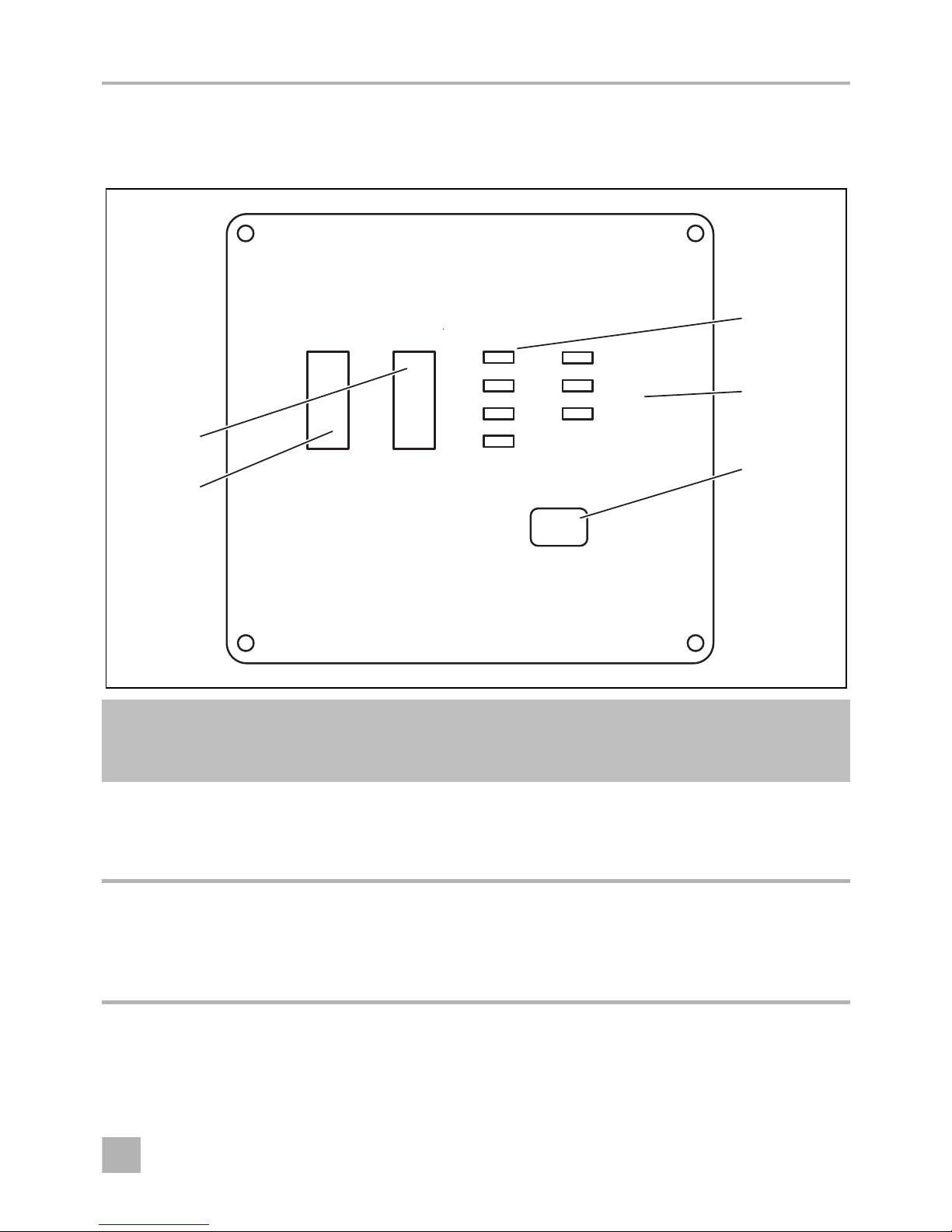
2Technical description
2.1 Power display
No. in
fig. 1,
page 3
Description Meaning
1Battery This bar graph shows the battery voltage in volts.
The display should be in the green area. If the display is above
or below in the red area, a warning tone sounds, the display
flashes and the inverter will be switched off.
2Output PowerThis bar graph displays the output power received by the
appliance as a percentage.
The display should be in the green or orange area. If the display
goes over into the red area, a warning tone sounds, the display
flashes and the inverter will be shut off.
1
Battery Output (%)
15
14
13
12
11
10
OVP
UVP
OTP
OLP
100
80
60
40
20
INV.
GRID
PWR.
SAV.
Remote Control
ON/OFF
Volts
Power
SinePower Accessory
5
3
4
1
2
MCR7-O-AU.book Seite 3 Donnerstag, 27. Oktober 2016 11:25 11
Page 4

Technical description MCR7
EN
4
2.2 Error displays
2.3 Status displays
No. in
fig. 1,
page 3
Description Meaning
3OVP This LED shows that the inverter is switching off due to
overvoltage.
UVP This LED shows that the inverter is switching off due to low
voltage.
OTP This LED shows that the inverter is switching off due to
overheating.
This LED switches off when the inverter has cooled down.
OLP This LED shows that the inverter is switching off due overloading
or short-circuiting.
No. in
fig. 1,
page 3
Description Meaning
4INV This LED shows that the inverter is in standby mode.
GRID No function
PWR SAV. This LED shows whether the inverter's energy saving mode
(standby) is activated.
• Constant glow: The energy saving mode is switched on.
• Flashing: The inverter is in energy saving mode.
• Off: The energy saving mode is switched off.
MCR7-O-AU.book Seite 4 Donnerstag, 27. Oktober 2016 11:25 11
Page 5

MCR7 Connection
EN
5
3Connection
➤ Insert one side of the RJ-11 cable in the socket “To inverter” (fig. 2 2, page 5).
➤ Insert the other side of the RJ-11 cable into the “Remote Port II” of the inverter.
Switching on/off by external signal
The remote control enables the optional switching on/off of the inverter by external signal:
➤ Loosen both Phillips screws and take off the cap (fig. 2 1, page 5).
➤ Set the desired connection on the jumper (fig. 2 3, page 5):
–Jumper open (A): Switching off inverter by positive battery voltage
When a plus signal is present on the control cable, the inverter is switched off (suitable e. g.
for roof air conditioners). If no signal is received, the inverter works in the previously activated function.
–Jumpers closed (B): Switching on inverter by positive battery voltage
When a plus signal is present on the control cable, the inverter is switched on and remains
on as long as the plus signal is present.
➤ Assemble the cap (fig. 2 1, page 5).
A
➤ Connect the 12 V control cable at the remote control connection (fig. 2 4, page 3).
NOTICE!
The control cable has to be secured by a suitable fuse (≤ 1 A.)
2
1
34
A
B
2
MCR7-O-AU.book Seite 5 Donnerstag, 27. Oktober 2016 11:25 11
Page 6

Service MCR7
EN
6
4Service
➤ With the “On/Off” button (fig. 2 2page 3) switch the inverter on or off.
✓ An acoustic signal sounds.
5Disposal
➤ Place the packaging material in the appropriate recycling waste bins wherever possible.
M
If you wish to finally dispose of the product, ask your local recycling centre or specialist
dealer for details about how to do this in accordance with the applicable disposal
regulations.
MCR7-O-AU.book Seite 6 Donnerstag, 27. Oktober 2016 11:25 11
Page 7

AUSTRIA
Dometic Austria GmbH
Neudorferstraße 108
A-2353 Guntramsdorf
+43 2236 908070
+43 2236 90807060
Mail: info@dometic.at
BENELUX
Dometic Branch Office Belgium
Zincstraat 3
B-1500 Halle
+32 2 3598040
+32 2 3598050
Mail: info@dometic.be
BRAZIL
Dometic DO Brasil LTDA
Avenida Paulista 1754, conj. 111
SP 01310-920 Sao Paulo
+55 11 3251 3352
+55 11 3251 3362
Mail: info@dometic.com.br
DENMARK
Dometic Denmark A/S
Nordensvej 15, Taulov
DK-7000 Fredericia
+45 75585966
+45 75586307
Mail: info@dometic.dk
FINLAND
Dometic Finland OY
Mestarintie 4
FIN-01730 Vantaa
+358 20 7413220
+358 9 7593700
Mail: info@dometic.fi
FRANCE
Dometic SAS
ZA du Pré de la Dame Jeanne
B.P. 5
F-60128 Plailly
+33 3 44633525
+33 3 44633518
Mail : vehiculesdeloisirs@dometic.fr
GERMANY
Dometic WAECO International GmbH
Hollefeldstraße 63 · D-48282 Emsdetten
+49 (0) 2572 879-195
+49 (0) 2572 879-322
Mail: info@dometic-waeco.de
HONG KONG
Dometic Group Asia Pacific
Suites 2207-11 · 22/F · Tower 1
The Gateway · 25 Canton Road,
Tsim Sha Tsui · Kowloon
+852 2 4611386
+852 2 4665553
Mail: info@waeco.com.hk
HUNGARY
Dometic Zrt. Sales Office
Kerékgyártó u. 5.
H-1147 Budapest
+36 1 468 4400
+36 1 468 4401
Mail: budapest@dometic.hu
MCR7-O-AU.book Seite 7 Donnerstag, 27. Oktober 2016 11:25 11
Page 8

AUSTRALIA
Dometic Australia Pty. Ltd.
1 John Duncan Court · Varsity Lakes QLD 4227
1800 212121 · +61 7 55076001
Mail: sales@dometic.com.au
www.dometic.com
ITALY
Dometic Italy S.r.l.
Via Virgilio, 3
I-47122 Forlì (FC)
+39 0543 754901
+39 0543 754983
Mail: vendite@dometic.it
JAPAN
Dometic KK
Maekawa-Shibaura, Bldg. 2
2-13-9 Shibaura Minato-ku
Tokyo 108-0023
+81 3 5445 3333
+81 3 5445 3339
Mail: info@dometic.jp
MEXICO
Dometic Mx, S. de R. L. de C. V.
Circuito Médicos No. 6 Local 1
Colonia Ciudad Satélite
CP 53100 Naucalpan de Juárez
Estado de México
+52 55 5374 4108
+52 55 5393 4683
Mail: info@dometic.com.mx
NETHERLANDS
Dometic Benelux B.V.
Ecustraat 3
NL-4879 NP Etten-Leur
+31 76 5029000
+31 76 5029019
Mail: info@dometic.nl
NEW ZEALAND
Dometic New Zealand Ltd.
PO Box 12011
Penrose
Auckland 1642
+64 9 622 1490
+64 9 622 1573
Mail: customerservices@dometic.co.nz
NORWAY
Dometic Norway AS
Østerøyveien 46
N-3232 Sandefjord
+47 33428450
+47 33428459
Mail: firmapost@dometic.no
POLAND
Dometic Poland Sp. z o.o.
Ul. Puławska 435A
PL-02-801 Warszawa
+48 22 414 3200
+48 22 414 3201
Mail: info@dometic.pl
PORTUGAL
Dometic Spain, S.L.
Branch Office em Portugal
Rot. de São Gonçalo nº 1 – Esc. 12
2775-399 Carcavelos
+351 219 244 173
+351 219 243 206
Mail: info@dometic.pt
RUSSIA
Dometic RUS LLC
Komsomolskaya square 6-1
RU-107140 Moscow
+7 495 780 79 39
+7 495 916 56 53
Mail: info@dometic.ru
SINGAPORE
Dometic Pte Ltd
18 Boon Lay Way 06–140 Trade Hub 21
Singapore 609966
+65 6795 3177
+65 6862 6620
Mail: dometic@dometic.com.sg
SLOVAKIA
Dometic Slovakia s.r.o. Sales Office
Bratislava
Nádražná 34/A
900 28 Ivánka pri Dunaji
/ +421 2 45 529 680
Mail: bratislava@dometic.com
SOUTH AFRICA
Dometic (Pty) Ltd.
Regional Office
South Africa & Sub-Saharan Africa
2 Avalon Road
West Lake View Ext 11
Modderfontein 1645
Johannesburg
+27 11 4504978
+27 11 4504976
Mail: info@dometic.co.za
SPAIN
Dometic Spain S.L.
Avda. Sierra del Guadarrama, 16
E-28691 Villanueva de la Cañada
Madrid
+34 902 111 042
+34 900 100 245
Mail: info@dometic.es
SWEDEN
Dometic Scandinavia AB
Gustaf Melins gata 7
S-42131 Västra Frölunda
+46 31 7341100
+46 31 7341101
Mail: info@dometicgroup.se
SWITZERLAND
Dometic Switzerland AG
Riedackerstrasse 7a
CH-8153 Rümlang
+41 44 8187171
+41 44 8187191
Mail: info@dometic.ch
UNITED ARAB EMIRATES
Dometic Middle East FZCO
P. O. Box 17860
S-D 6, Jebel Ali Freezone
Dubai
+971 4 883 3858
+971 4 883 3868
Mail: info@dometic.ae
UNITED KINGDOM
Dometic UK Ltd.
Dometic House, The Brewery
Blandford St. Mary
Dorset DT11 9LS
+44 344 626 0133
+44 344 626 0143
Mail: customerservices@dometic.co.uk
USA
Dometic RV Division
1120 North Main Street
Elkhart, IN 46515
+1 574-264-2131
4445102064 10/2016
MCR7-O-AU.book Seite 8 Donnerstag, 27. Oktober 2016 11:25 11
 Loading...