

Page 1

ENDEFRESPTITNL
DA
SV
NOFIRUPLSKCSHU
ENERGY & LIGHTING
PERFECTCHARGE
MCA1215, MCA1225, MCA1235,
MCA1250, MCA1280, MCA2415,
MCA2425, MCA2440
Battery charger
Installation and Operating Manual. . . . . . . . 8
Batterielader
Montage- und Bedienungsanleitung. . . . .35
Chargeur de batteries
Instructions de montage
et de service . . . . . . . . . . . . . . . . . . . . . . . . .64
Cargador de batería
Instrucciones de montaje y de uso. . . . . . .95
Carregador de baterias
Instruções de montagem e manual de
instruções . . . . . . . . . . . . . . . . . . . . . . . . . .125
Caricatore per batterie
Istruzioni di montaggio e d’uso . . . . . . . .153
Acculader
Montagehandleiding en
gebruiksaanwijzing . . . . . . . . . . . . . . . . . .182
Batterilader
Monterings- og betjeningsvejledning . . .210
Batteriladdare
Monterings- och bruksanvisning. . . . . . . 236
Batterilader
Monterings- og bruksanvisning. . . . . . . . 262
Akkulaturi
Asennus- ja käyttöohje . . . . . . . . . . . . . . . 288
Устройство для заряда
аккумуляторных батарей
Инструкция по монтажу и эксплуатации 314
Ładowarka akumulatorowa
Instrukcja montażu i obsługi. . . . . . . . . . .343
Nabíjačka batérií
Návod na montáž a uvedenie
do prevádzky. . . . . . . . . . . . . . . . . . . . . . . 373
Nabíječka baterií
Návod k montáži a obsluze . . . . . . . . . . . 401
Akkumulátortöltő
Szerelési és használati útmutató . . . . . . .427
Page 2

Page 3

MCA1215 – MCA2440
12345
AC INPUT
DC OUTPUT
1234
STATUS
TEMP/LIN1 LIN2
ESB
12345
AC INPUT
DC OUTPUT
123
STATUS
TEMP/LIN1 LIN2
ESB
AC INPUT
12345
STATUS
TEMP/LIN1 LIN2
1234
DC OUTPUT
1
234
987
56
1
23456
987
1
2346 5
87
MCA1215
MCA1225/1235/2415
MCA1250/1280/2425/2440
1
3
Page 4
21
21
MCA1250/1280/2425/2440
MCA1215/1225/1235/2415
2
MCA1215 – MCA2440
4
Page 5
MCA1215 – MCA2440
LIN
MPC01 MCA-HS1 (IBS)
MCA12xx
3
MCA-RC1
MCA-TS1MCA-HS1 (IBS)
LIN
MCA12xx
4
5
Page 6

MCA1215 – MCA2440
LIN
2
376 4
1
5
MCA12xx
5
MCA-RC1 MCA-TS1
LIN2
TEMP/LIN1
MCA24xx
3
12
6
7
9
CN 2
12345
8
TEMP/LIN 1/LIN 2
6
6
ESB
1
RJ-11 6P6C
Page 7

MCA1215 – MCA2440
Sleep
Mode
On / Off
MCA-RC1
1
2
3
MCA-RC1
1
6
1
6
1
2
3
4
5
6
RJ11
0
a
1
234
OFF
ON
STATUS
DC OUTPUT
7
Page 8

EN
MCA1215 – MCA2440
Please read this instruction manual carefully before installation and first
use, and store it in a safe place. If you pass on the product to another
person, hand over this instruction manual along with it.
Table of contents
1 Explanation of symbols. . . . . . . . . . . . . . . . . . . . . . . . . . . . . . . . . . . . . . . . . . .9
2 General safety instructions . . . . . . . . . . . . . . . . . . . . . . . . . . . . . . . . . . . . . . . .9
3 Intended use . . . . . . . . . . . . . . . . . . . . . . . . . . . . . . . . . . . . . . . . . . . . . . . . . .14
4 Scope of delivery . . . . . . . . . . . . . . . . . . . . . . . . . . . . . . . . . . . . . . . . . . . . . .14
5 Accessories . . . . . . . . . . . . . . . . . . . . . . . . . . . . . . . . . . . . . . . . . . . . . . . . . . .15
6 Technical description . . . . . . . . . . . . . . . . . . . . . . . . . . . . . . . . . . . . . . . . . . .15
7 Installing the device . . . . . . . . . . . . . . . . . . . . . . . . . . . . . . . . . . . . . . . . . . . .18
8 Connecting the device . . . . . . . . . . . . . . . . . . . . . . . . . . . . . . . . . . . . . . . . . 20
9 Using the device . . . . . . . . . . . . . . . . . . . . . . . . . . . . . . . . . . . . . . . . . . . . . . 26
10 Maintaining and cleaning the device . . . . . . . . . . . . . . . . . . . . . . . . . . . . . . 28
11 Troubleshooting . . . . . . . . . . . . . . . . . . . . . . . . . . . . . . . . . . . . . . . . . . . . . . 29
12 Warranty . . . . . . . . . . . . . . . . . . . . . . . . . . . . . . . . . . . . . . . . . . . . . . . . . . . . 30
13 Disposal . . . . . . . . . . . . . . . . . . . . . . . . . . . . . . . . . . . . . . . . . . . . . . . . . . . . . 30
14 Technical data . . . . . . . . . . . . . . . . . . . . . . . . . . . . . . . . . . . . . . . . . . . . . . . . .31
8
Page 9

EN
MCA1215 – MCA2440 Explanation of symbols
1 Explanation of symbols
DANGER!
D
!
!
A
I
Safety instruction: Failure to observe this instruction will cause fatal or
serious injury.
WARNING!
Safety instruction: Failure to observe this instruction can cause fatal or
serious injury.
CAUTION!
Safety instruction: Failure to observe this instruction can lead to injury.
NOTICE!
Failure to observe this instruction can cause material damage and impair
the function of the product.
NOTE
Supplementary information for operating the product.
2 General safety instructions
The manufacturer accepts no liability for damage in the following cases:
• Faulty assembly or connection
• Damage to the product resulting from mechanical influences and excess voltage
• Alterations to the product without express permission from the manufacturer
• Use for purposes other than those described in the operating manual
WARNING!
!
Note the following basic safety information when using electrical
devices to protect against:
•Electric shock
•Fire hazards
•Injury
9
Page 10

EN
General safety instructions MCA1215 – MCA2440
2.1 General safety
DANGER!
D
!
• In the event of fire, use a fire extinguisher which is suitable for electrical
devices.
WARNING!
• Only use the device as intended.
• Disconnect the device from the mains:
– Before cleaning and maintenance
–After use
– Before changing a fuse
• If you disassemble the device:
– Detach all connections
– Make sure that no voltage is present at any of the inputs and out-
puts
• The device may not be used if the device itself or the connection cable
are visibly damaged.
• If this power cable for this device is damaged, it must be replaced by
the manufacturer, customer service or a similarly qualified person in
order to prevent safety hazards.
• This device may only be repaired by qualified personnel. Inadequate
repairs may cause serious hazards.
• This device can be used by children aged 8 years or over, as well as by
persons with diminished physical, sensory or mental capacities or a
lack of experience and/or knowledge, providing they are supervised
or have been taught how to use the device safely and are aware of the
resulting risks.
• Electrical devices are not toys.
Always keep and use the appliance out of the reach of children.
• Children must be supervised to ensure that they do not play with the
device.
A
10
NOTICE!
• Before start-up, check that the voltage specification on the type plate
is the same as that of the power supply.
• Ensure that other objects cannot cause a short circuit at the contacts
of the device.
• Never pull the plug out of the socket by the connection cable.
• Store the device in a dry and cool place.
Page 11

EN
MCA1215 – MCA2440 General safety instructions
2.2 Safety when installing the device
DANGER!
D
!
A
2.3 Safety when connecting the device electronically
D
• Never mount the device anywhere where there is a risk of gas or dust
explosion.
CAUTION!
• Ensure that the device is standing firmly.
The device must be set up and fastened in such a way that it cannot tip
over or fall down.
NOTICE!
• Do not expose the device to a heat source (such as direct sunlight or
heating). Avoid additional heating of the device in this way.
• Set up the device in a dry location where it is protected against splashing water.
DANGER! Danger of electrocution
• For installation on boats:
If electrical devices are incorrectly installed on boats, corrosion damage might occur. Have the device installed by a specialist (marine)
electrician.
• If you are working on electrical systems, ensure that there is somebody
close at hand who can help you in emergencies.
!
!
WARNING!
• Always use sockets which are grounded and secured by residual current circuit breakers.
• Make sure that the lead has a sufficient cross-section.
• Lay the cables so that they cannot be damaged by the doors or the
bonnet.
Crushed cables can lead to serious injury.
CAUTION!
• Lay the cables so that they cannot be tripped over or damaged.
11
Page 12

EN
General safety instructions MCA1215 – MCA2440
NOTICE!
A
2.4 Operating the device safely
D
!
• Use ductwork or cable ducts if it is necessary to lay cables through
metal panels or other panels with sharp edges.
•Do not lay the 230 V mains cable and the 12 V DC cable in the same
duct.
•Do not lay the cable so that it is loose or heavily kinked.
• Fasten the cables securely.
• Do not pull on the cables.
DANGER! Danger of electrocution
• Do not touch exposed cables with your bare hands. This applies especially when operating the device from the AC mains.
• To be able to disconnect the device quickly from the mains, the socket
must be close to the device and be easily accessible.
WARNING!
• Only use the device in closed, well-ventilated rooms.
•Do not operate the device in systems with lead acid batteries. These
batteries give off explosive hydrogen gas that can be ignited by sparks
on electrical connections.
!
A
12
CAUTION!
•Do not operate the device
– In salty, wet or damp environments
– In the vicinity of corrosive fumes
– In the vicinity of combustible materials
– In areas where there is a danger of explosions.
• Before starting the device, ensure that the power supply line and the
plug are dry.
• Always disconnect the power supply when working on the device.
• Please observe that parts of the device may still conduct voltage even
if the fuse has blown.
• Do not disconnect any cables when the device is still in use.
NOTICE!
• Make sure the air inlets and outlets of the device are not covered.
• Ensure good ventilation.
Page 13

EN
MCA1215 – MCA2440 General safety instructions
2.5 Safety precautions when handling batteries
WARNING!
!
!
• Batteries contain aggressive and caustic acids. Avoid battery fluid
coming into contact with your body. If your skin does come into
contact with battery fluid, wash the part of your body in question
thoroughly with water.
If you sustain any injuries from acids, contact a doctor immediately.
CAUTION!
• When working on the batteries, do not wear any metal objects such as
watches or rings.
Lead acid batteries can cause short circuits which can cause serious
injuries.
• Danger of explosions!
Never attempt to charge a frozen or defective battery.
Place the battery in a frost-free area and wait until the battery has acclimatised to the ambient temperature. Then start the charging process.
• Wear goggles and protective clothing when you work on batteries.
Do not touch your eyes when you are working on the battery.
• Do not smoke and ensure that no sparks can arise in the vicinity of the
engine or battery.
A
NOTICE!
• Only use rechargeable batteries.
• Prevent any metal parts from falling on the battery. This can cause
sparks or short-circuit the battery and other electrical parts.
• Make sure the polarity is correct when connecting the battery.
• Follow the instructions of the battery manufacturer and those of the
manufacturer of the system or vehicle in which the battery is used.
• If you need to remove the battery, first disconnect the earth
connection. Disconnect all connections and all consumers from the
battery before removing it.
13
Page 14

EN
Intended use MCA1215 – MCA2440
3 Intended use
The PerfectCharge MCA360 battery charger can charge or supply a retention
voltage to batteries which are used to generate power in vehicles or on boats.
The MCA charger can be used to continuously charge supply or starter batteries.
This allows the batteries to be charged and to maintain a high charge level:
• 12 V batteries: MCA1215, MCA 1225, MCA1235, MCA 1250, MCA1280
• 24 V batteries: MCA2415, MCA 2425, MCA2440
The MCA battery charger are designed to charge the following battery types:
• Lead starter batteries
• Lead gel batteries
• Absorbed glass mat (AGM) batteries
Never use the devices to charge other battery types (such as NiCd or NiMH).
WARNING! Danger of explosions
!
• Do not charge batteries with a cell short circuit. The oxyhydrogen
they produce can cause explosions.
• Do not charge lead batteries in unventilated rooms. The oxyhydrogen they produce can cause explosions.
• Do not charge nickel cadmium and non-rechargeable batteries with
the charger. The cases of these batteries can burst explosively.
4Scope of delivery
Quantity Description
1 Battery charger
2 230 V power cable
3 Installation and operating manual
Check before starting up the device that all parts are available belonging to the
scope of delivery.
14
Page 15

EN
MCA1215 – MCA2440 Accessories
5Accessories
Available as accessory (not included in scope of delivery):
Description Reference no.
Remote Control MCA-RC1 9600000100
Temperature sensor MCA-TS1 9600000099
Battery sensor MCA-HS1 (IBS) 9600000101
Battery Management System PerfectControl MPC01 9600000122
6 Technical description
The low weight and compact construction of the battery charger allow for easy
installation in mobile homes, commercial vehicles or motor and sailing yachts. It
charges batteries that are used on board vehicles or boats to generate power or
supplies them with a retention voltage so that they do not discharge.
A control lamp on the device enables constant monitoring in the battery charger.
The device has the following protective systems:
• Short circuit
• Overheating protection
• with sensor (accessory): Battery overheating
The device can also be integrated into a LIN bus using two connections.
The cooling system uses fans whose speed depends on the charging power and can
be switched off using an external switch.
15
Page 16

EN
Technical description MCA1215 – MCA2440
6.1 Device versions
The PerfectCharge MCA battery chargers are available in different versions.
Your MAC battery charger can be used to charge batteries up to a specified battery
capacity (see chapter “Technical data” on page 31):
• MCA1215: suitable for charging one supply battery and one starter battery
• MCA 1225, MCA1235: suitable for charging up to two supply batteries and one
starter battery
• MCA1250, MCA1280: suitable for charging up to three supply batteries
• MCA2415: suitable for charging up to two supply batteries
• MCA2425, MCA 2440: suitable for charging up to three supply batteries
For the identification of your device, see the reference number on the type plate.
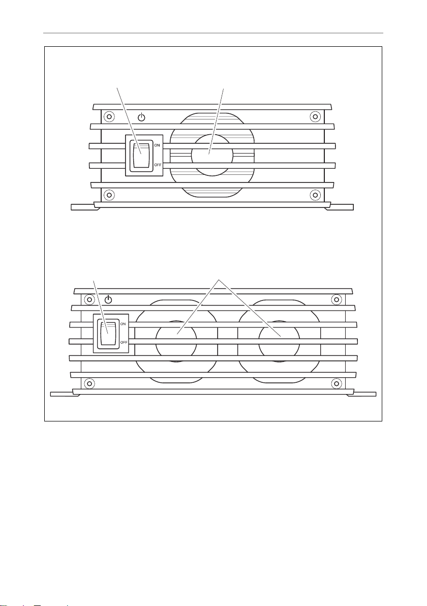
6.2 Connections and controls
NOTE
I
The version for continental Europe is depicted.
No. in
fig. 1, page 3
1 Mains connection
2 LIN2 bus connection
3 TENMP/LIN1 bus connection
4 CN2 socket for Alarm and Fan
5 Status LED
6DIP switch
7 Battery terminals (+)
8 Battery terminals (–)
9 Starter battery connection
16
Explanation/function
(MCA1215, MCA1225, MCA1235 only)
Page 17

EN
MCA1215 – MCA2440 Technical description
U0 U
U
I
I
1
100 %
6 %
234 65
t
U/V
I/A
No. in
fig. 2, page 4
1 On/Off switch
2Fan
Explanation/function
6.3 Battery charging function
The charging characteristics are referred to as modified IU0U characteristics.
1: I phase (bulk)
At the beginning of the charging process, the flat battery is charged with a constant
current (100 % charge current) until the battery voltage reaches the charging voltage. The charging current decreases when the battery has reached this charging
level.
17
Page 18

EN
Installing the device MCA1215 – MCA2440
2, 3, 4: U0 phase (absorption)
Now the three-stage absorption charging process (U0 phase) begins, where the
duration depends on the battery. The voltage remains constant (U0). In the first
2 minutes, the charging of the battery is determined. Then the main charging phase
begins when the battery is fully charged.
Once the battery is completely charged, or the charging current is below 6 % of the
rated charging current for 15 minutes, the U0 phase has finished.
5: U phase (float)
After the U0 phase, the battery charger switches to conservation charging function
(U phase).
If DC loads are connected, they are powered by the device. Only if the power
required exceeds the capacity of the device is this surplus power provided by the
battery. The battery is then discharged until the device re-enters the I phase and
charges the battery.
6: 12-day conditioning
Every 12 days, the battery charger switches back to phase 1 for 85 min in order to
revive the battery. This prevents any fatigue symptoms such as sulphation.
7 Installing the device
When selecting the installation location, observe the following instructions:
• The device can be installed horizontally or vertically.
•Do not install the device
– In wet or damp environments
– In dusty environments
– In the vicinity of combustible materials
– In areas where there is a danger of explosions.
• The place of installation must be well ventilated. A ventilation system must be
available for installations in small, enclosed spaces. The clearance around the
device must be at least 25 cm.
• The air inlet on the underside and the air outlet on the back of the device must
remain clear.
• For ambient temperatures higher than 40 °C (such as in engine or heating
compartments, or direct sunlight), the heat from the device under load can lead
to reduced output.
18
Page 19

EN
MCA1215 – MCA2440 Installing the device
• The device must be installed on a level and sufficiently sturdy surface.
• Do not install the device in the same area as the batteries.
• Do not install the device above batteries, because they can emit corrosive
sulphur fumes that will damage the device.
NOTICE!
A
For installation and mounting you will need the following tools:
• Pen for marking
•Drill bit set
•Drill
• Screwdriver
To secure the device in place you will need:
• Machine bolts (M4) with washers and self-locking nuts or
• self-tapping screws or wood screws.
Fasten the device as follows:
Before drilling any holes, make sure that no electrical cables or other
parts of the vehicle can be damaged by drilling, sawing and filing.
➤ Hold the device against the installation location.
➤ Mark the fastening points.
➤ Fasten the device with one screw through each hole in the holders.
19
Page 20

EN
Connecting the device MCA1215 – MCA2440
8 Connecting the device
8.1 Connecting to battery and power supply
Connecting the battery
Observe the following instructions when connecting the battery:
CAUTION!
!
• Make sure the battery terminals are clean when connecting them.
• Make sure the plug connector is fitted securely.
• Select a connection cable with a sufficient cross-section (see chapter “Technical
data” on page 31).
• Lay the cables in accordance with VDE°100 (Germany).
• Connect the negative cable directly to the negative terminal of the battery, and
not to the chassis of a vehicle or boat.
• Use the following cable colours:
– Red: positive connection
– Black: negative connection
• Do not reverse the polarity. Reversing the polarity can cause damage to the
device.
• Avoid coming into contact with the battery fluid.
• Batteries with a cell short circuit may not be charged, as explosive
gases may form due to overheating of the battery.
➤ Lay the positive cable from the battery charger to the positive terminal of the
battery and connect it.
➤ Lay the negative cable from the battery charger to the negative terminal of the
battery and connect it.
Connecting the 230 V power supply
➤ Plug the 230 V connection cable included in the delivery into the MCA battery
charger‘s “AC INPUT” socket.
➤ Connect the device with the he 230 V connection cable to a 230 V socket which
is protected by a residual current circuit breaker.
20
Page 21

EN
MCA1215 – MCA2440 Connecting the device
8.2 Charge versions
fig. 3, page 5 fig. 4, page 5
Battery sensor
MCA-HS1 (IBS)
(12 V only)
–– ––
✓ – ✓ –
✓✓ – ✓
Perfect Control
MPC01
(12 V only)
Remote control
MCA-RC1
✓✓
Temperature sensor
MCA-TS1 or
Battery sensor
MCA-HS1 (IBS)
(12 V only)
– without; ✓ with
Charging the battery
➤ Connect the battery to the “DC OUTPUT” socket of the MCA battery charger.
• Make sure the polarity of the connections is correct.
Charging the starter battery (MCA1215, 1225, 1235 only)
➤ Connect the starter battery to the “ESB” socket of the MCA battery charger.
• Make sure the polarity of the connections is correct.
Charging using the temperature sensor MCA-TS1 (accessory)
➤ Connect the temperature sensor to the TEMP/LIN connection.
✓ The charging voltage is adjusted according to the temperature measured.
Charging using the IBS battery sensor MCA-HS1 (accessory) (12 V only)
➤ Connect the battery sensor to the TEMP/LIN connection.
✓ The battery sensor transmits the battery temperature and the battery voltage to
the charger via the LIN communication port. The charging voltage is regulated
according to the temperature. Any potential loss of voltage in the connecting
cables is also compensated.
21
Page 22

EN
Connecting the device MCA1215 – MCA2440
Charging using the battery management system PerfectControl MPC01
(accessory) (12 V only)
➤ Set the DIP switches 1 to 3 on the MCA battery charger to “ON” (chapter “Setting
the DIP switches” on page 24).
You can find detailed information in the operating manual for MPC01.
Charging using the remote control MCA-RC1 (accessory)
NOTE
I
➤ Insert one end of the RJ-11 cable into the socket (fig. 0 3, page 7) of the
MCA-RC1.
➤ Insert the other end of the RJ-11 cable into the TEMP/LIN1 socket on the MCA
battery charger.
The length of the RJ-11 cable may not exceed 7 m.
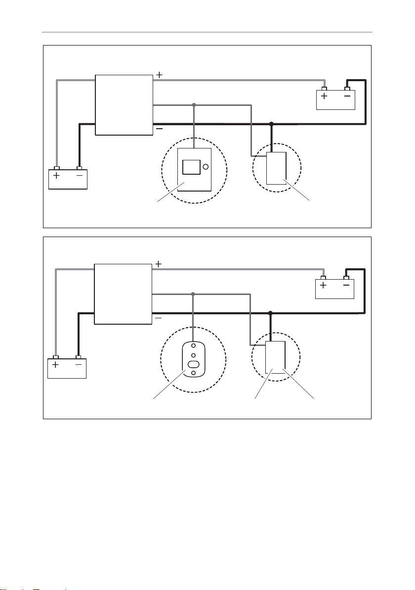
8.3 Wiring diagrams
Example of a wiring diagram, 12 V: see fig. 5, page 6.
No. in
fig. 5, page 6
1 MCA charger
2Consumer
3 PerfectControl MPC01
4 12 V battery sensor IBS
5 12 V battery
6Fuse
7 Starter battery
Example of a wiring diagram, 24 V: see fig. 6, page 6.
No. in
fig. 6, page 6
1 MCA charger
2 12 V battery
3 Starter battery
Explanation/function
Explanation/function
22
Page 23

EN
MCA1215 – MCA2440 Connecting the device
8.4 Pin assignment
The pins for the TEMP/LIN1 bus socket are assigned as follows:
Pin in
fig. 7, page 6
1 R_VCC
2GND
3TEMP
4BAT –
5 LIN BUS DATA I/O
6BAT +
Allocation
The pins for the LIN2 bus socket are assigned as follows:
Pin in
fig. 7, page 6
1 R_VCC
2BAT –
3NC
4BAT –
5 LIN BUS DATA I/O
6BAT +
Allocation
The pins for the CN2 socket (alarm signal and fan control) are assigned as follows:
Pin in
fig. 8, page 6
1 NC (Normally Closed): normally closed contact
2 NO (Normally Open): normally open contact
3 COM (Common): common contact
4 Sleep mode control
5GND
4 – 5 bridged Sleep mode on
4 – 5 open Sleep mode off
Allocation
23
Page 24

EN
Connecting the device MCA1215 – MCA2440
The pins for the ESB socket (starter battery connection) are assigned as follows:
Pin in
fig. 9, page 6
+VCC
–GND
Allocation
8.5 Setting the DIP switches
You can adjust the device using the DIP switch.
S1 is used to set the voltage at which the device switches over from the I phase (bulk)
to the U0 phase (absorption) (also see chapter “Battery charging function” on
page 17). S3 must be set to “OFF”.
S2 is used to set the retention voltage. S3 must be set to “OFF”.
When a battery sensor is connected, the output voltages is adapted to the
temperature for these two functions:
• MCA 12xx: –20 mV/°C
• MCA 24xx: –40 mV/°C
S3 activates the power mode when either S1 or S2, or both, are set to “Off”. In power
mode, the short circuit, overvoltage and overheating protection are controlled by
the internal sensor.
When S1, S2 and S3 are set to “On”, then the function control by external devices is
activated. Among others the type of battery and the charging voltage are set using
the external device in this mode.
S4 regulates the fan function. When S4 is set to “On”, then the fan is switched to
sleep mode (noise-reduced mode). When S4 is set to “Off”, then the fan is not
regulated.
24
Page 25

EN
MCA1215 – MCA2440 Connecting the device
➤ Use the DIP switches (fig. a page 7) to set the required functions and values:
– To set the switchover voltage:
Switch 1 Switch 3 Switchover voltage
ON OFF 14.4 V / 28.8 V
OFF OFF 14.7 V / 29.4 V
– To set the retention voltage:
Switch 2 Switch 3 Retention voltage
ON OFF 13.5 V / 27.0 V
OFF OFF 13.8 V / 27.6 V
– To set the power mode:
Switch 1 Switch 2 Switch 3 Constant voltage
MCA12.. MCA 24..
OFF OFF ON 13.2 V 26.4 V
OFF ON ON 13.8 V 27.6 V
ON OFF ON 14.4 V 28.8 V
– Enabling the control for external devices (such as MPC01, does not apply to
MCA-RC1):
Switch 1 Switch 2 Switch 3
ON ON ON
– To activate sleep mode:
Switch 4
ON
25
Page 26
EN
Using the device MCA1215 – MCA2440
9 Using the device
➤ Set the On/off switch to “On”.
To switch off the device set the On/off switch to “On”.
✓ Depending on the charging condition of the battery, the battery charger starts
charging or supplies a retention voltage.
✓ The “Status” LED (fig. 1 5, page 3) displays the operating status (see following
table and chapter “Battery charging function” on page 17).
Display Meaning
Orange, quickly flashing Phase 1
Orange, slowly flashing Phase 2
Orange, constantly lit Phase 3
Green, constantly lit Phase 4
Green, slowly flashing Phase 5
Red, constantly lit Short circuit or defective fuse
Red, quickly flashing Battery or battery charger is overheating
Red, slowly flashing Battery undervoltage or overload
Red, 1x Quick flash, 2x Long flash
Fan fault
Red, slow double flash Fault at the starter battery connection
NOTE
I
In the event of a fault (the Status LED is red), refer to chapter “Troubleshooting” on page 29).
26
Page 27

EN
MCA1215 – MCA2440 Using the device
When you have connected the remote control MCA-RC1 (accessory)
➤ Activate or deactivate sleep mode (noise reduced mode) using the “Sleep
Mode” button (fig. 0 2, page 7).
The fan is not regulated in sleep mode.
✓ The LED (fig. 0 1, page 7) on the MCA-RC1 indicates the operating status (see
following table).
Mode Display Meaning
Sleep mode activated Orange, constantly lit Phase 1 to 5
Sleep mode
deactivated
Fault Red, constantly lit Short circuit or defective fuse
NOTE
I
In the event of a fault (the Status LED is red), refer to chapter “Troubleshooting” on page 29).
Green, slowly
flashing
Green, constantly lit Phase 5
Red, quickly flashing Battery or battery charger is overheating
Red, slowly flashing Battery undervoltage or overload
Red, double flash Fan fault
Red, slow double
flash
Phase 1 to 4
Fault at the starter battery connection
27
Page 28

EN
Maintaining and cleaning the device MCA1215 – MCA2440
10 Maintaining and cleaning the device
NOTICE!
A
➤ Disconnect the device from the 230 V power supply.
➤ Disconnect the device from the battery.
➤ Prevent the device from being switched on.
➤ Occasionally clean the device with a damp cloth.
➤ Regularly clean the vents.
➤ Check the electrical wiring at least once a year.
Repair any defects such as loose connections or burnt cables.
Do not use any sharp or hard objects for cleaning since they may
damage the device.
28
Page 29

EN
MCA1215 – MCA2440 Troubleshooting
11 Troubleshooting
The “Status” LED (fig. 1 5, page 3) displays the fault:
LED display Cause Remedy
Red, slowly flashing Battery undervoltage or bat-
tery overload
Defective battery Replace the battery.
Red, slowly flashing Overheating Improve the ventilation of the bat-
Red, permanently lit Short circuit or reversed
polarity
Red, double flash Fan fault Check the fan for dirt or damage.
Red, slow double
flash
NOTE
I
If you have detailed questions on the battery specifications, please
contact the battery manufacturer.
Fault at the starter battery
connection
Check the battery.
Switch the battery charger off and
on again.
tery charger or battery.
Make sure that no ventilation open-
ings are covered.
If necessary, reduce the ambient
temperature.
Connect the battery charger with
the correct polarity.
Rectify the short circuit.
Check if the fuse has triggered and
replace it if necessary.
Check the starter battery connection for a short circuit.
29
Page 30

EN
Warranty MCA1215 – MCA2440
12 Warranty
The statutory warranty period applies. If the product is defective, please contact the
manufacturer's branch in your country (see the back of the instruction manual for the
addresses) or your retailer.
For repair and guarantee processing, please include the following documents when
you send in the device:
• A copy of the receipt with purchasing date
• A reason for the claim or description of the fault
13 Disposal
➤ Place the packaging material in the appropriate recycling waste bins wherever
possible.
If you wish to finally dispose of the product, ask your local recycling centre
or specialist dealer for details about how to do this in accordance with the
M
applicable disposal regulations.
30
Page 31

EN
MCA1215 – MCA2440 Technical data
14 Technical data
General technical data
MCA12xx, MCA24xx
Battery types: Lead-acid, gel, AGM, Li-Ion
Heat dissipation: Fan
Charge mode: 5-level
Maximum ambient temperature: –20 °C – +50 °C
Storage temperature: –40 °C – +85 °C
Air humidity: 20 – 90 %
Temperature coefficient: ±0.03%/°C (0 – 50°C)
Temperature compensation (MCA12xx)
Temperature compensation (MCA24xx):
Vibration: 10 – 500 Hz
2 g for 10 min/cycle within 60 minutes for X, Y and
Voltage insulation: I/P – O/P: 4 kVw
Insulation resistance: I/P – O/P: 100 MΩ/500 Vg
Alarm signal: via relay contact
Communication: via LIN-BUS
Sleep mode (noise-reduced mode): via remote control (accessory) or DIP switch
Remote control (accessory): On/off switch, three-colour LED, sleep mode
Testing/certification:
–20 mV/°C (battery sensor)
–40 mV/°C (battery sensor)
Z axis
I/P – FG: 1.7 kVw
O/P – FG : 0.7 kVw
option
31
Page 32

EN
Technical data MCA1215 – MCA2440
Protective devices
MCA12xx, MCA24xx
Output side short circuit: Current is reduced to 25 % of the
maximum current
Overvoltage: 16 V
Battery charger over temperature: 100 °C ± 5 °C (measured internally)
Battery over temperature: 52 °C ± 5 °C (with battery sensor)
Input data
MCA1215 MCA 1225 MCA 1235 MCA 1250 MCA1280
Rated input voltage: 90 – 260 Vw
Output factor correction: > 97% (full load)
Input frequency: 50 Hz – 60 Hz
Efficiency at 230 Vw:87%
Leakage current: < 1 mA at 240 Vw
Input current at 100 Vw: 2.5 A 4.1A 6.2 A 8.24 A 13.3 A
Input current at 240 Vw: 1.07A 1.8A 2.8A 3.6A 5.4A
MCA2415 MCA2425 MCA2440
Rated input voltage: 90 – 260 Vw
Output factor correction: > 97% (full load)
Input frequency: 50 Hz – 60 Hz
Efficiency at 230 Vw:90%
Leakage current: < 1 mA at 240 Vw
Input current at 100 Vw:4.2A8.3A13.3A
Input current at 240 Vw: 1.7 A 3.6 A 5.4 A
32
Page 33

EN
MCA1215 – MCA2440 Technical data
Output data
MCA1215 MCA 1225 MCA 1235 MCA 1250 MCA1280
Charging voltage: 14.4 V / 14.7 V
Retention voltage: 13.8 V
Rated charging current: 15 A 25 A 35 A 50 A 80 A
Charging current: 0 – 15 A 0 – 25 A 0 – 35 A 0 – 50 A 0 – 80 A
Outputs: 12233
ESB outputs
(Starter battery):
ESB charging voltage : 13.8 V 13.8 V 13.8 V – –
ESB charging current: 2 A 2 A 2 A – –
Charging voltage: 28.8 V / 29.4 V
Retention voltage: 27.6 V
Rated charging current: 12.5 A 25 A 40 A
Charging current: 0 – 12.5 A 0 – 25 A 0 – 40 A
Outputs: 233
111––
MCA2415 MCA2425 MCA2440
33
Page 34

EN
Technical data MCA1215 – MCA2440
Dimensions and weight:
MCA1215 MCA 1225 MCA1235
Dimensions L x W x H (mm): 238 x 179 x 63 238 x 179 x 63 274 x 179 x 63
Weight: 1.6 kg 1.7 kg 1.9 kg
MCA1250 MCA1280
Dimensions L x W x H (mm): 283 x 208.5 x 75 303x208.5x75
Wei ght: 3 .1 kg 3. 9 kg
MCA2415 MCA2425 MCA2440
Dimensions L x W x H (mm): 238 x 179 x 63 283 x 208.5 x 75 303x208.5x75
Weight: 1.6 kg 2.9 kg 3.9 kg
Technical data MCA-RC1 (accessory)
MCA-RC1
Rated input voltage: 10.5 – 15 Vg
Standby current consumption: < 40 mA
Maximum ambient temperature: –10 °C – +45 °C
Storage temperature: –30 °C – +70 °C
34
Page 35

DE
MCA1215 – MCA2440
Bitte lesen Sie diese Anleitung vor Einbau und Inbetriebnahme sorgfältig
durch und bewahren Sie sie auf. Geben Sie sie im Falle einer Weitergabe
des Produktes an den Nutzer weiter.
Inhaltsverzeichnis
1 Erklärung der Symbole . . . . . . . . . . . . . . . . . . . . . . . . . . . . . . . . . . . . . . . . . 36
2 Allgemeine Sicherheitshinweise . . . . . . . . . . . . . . . . . . . . . . . . . . . . . . . . . 36
3 Bestimmungsgemäßer Gebrauch . . . . . . . . . . . . . . . . . . . . . . . . . . . . . . . . 42
4 Lieferumfang . . . . . . . . . . . . . . . . . . . . . . . . . . . . . . . . . . . . . . . . . . . . . . . . . 42
5 Zubehör. . . . . . . . . . . . . . . . . . . . . . . . . . . . . . . . . . . . . . . . . . . . . . . . . . . . . 43
6 Technische Beschreibung . . . . . . . . . . . . . . . . . . . . . . . . . . . . . . . . . . . . . . 43
7 Gerät montieren . . . . . . . . . . . . . . . . . . . . . . . . . . . . . . . . . . . . . . . . . . . . . . 46
8 Gerät anschließen . . . . . . . . . . . . . . . . . . . . . . . . . . . . . . . . . . . . . . . . . . . . . 48
9 Gerät benutzen . . . . . . . . . . . . . . . . . . . . . . . . . . . . . . . . . . . . . . . . . . . . . . . 55
10 Gerät pflegen und reinigen . . . . . . . . . . . . . . . . . . . . . . . . . . . . . . . . . . . . . 57
11 Fehlerbeseitigung. . . . . . . . . . . . . . . . . . . . . . . . . . . . . . . . . . . . . . . . . . . . . 58
12 Gewährleistung. . . . . . . . . . . . . . . . . . . . . . . . . . . . . . . . . . . . . . . . . . . . . . . 59
13 Entsorgung . . . . . . . . . . . . . . . . . . . . . . . . . . . . . . . . . . . . . . . . . . . . . . . . . . 59
14 Technische Daten . . . . . . . . . . . . . . . . . . . . . . . . . . . . . . . . . . . . . . . . . . . . . 60
35
Page 36

DE
Erklärung der Symbole MCA 1215 – MCA2440
1 Erklärung der Symbole
GEFAHR!
D
!
!
A
I
Sicherheitshinweis: Nichtbeachtung führt zu Tod oder schwerer
Verletzung.
WARNUNG!
Sicherheitshinweis: Nichtbeachtung kann zu Tod oder schwerer
Verletzung führen.
VORSICHT!
Sicherheitshinweis: Nichtbeachtung kann zu Verletzungen führen.
ACHTUNG!
Nichtbeachtung kann zu Materialschäden führen und die Funktion des
Produktes beeinträchtigen.
HINWEIS
Ergänzende Informationen zur Bedienung des Produktes.
2 Allgemeine Sicherheitshinweise
Der Hersteller übernimmt in folgenden Fällen keine Haftung für Schäden:
• Montage- oder Anschlussfehler
• Beschädigungen am Produkt durch mechanische Einflüsse und Überspannungen
• Veränderungen am Produkt ohne ausdrückliche Genehmigung vom Hersteller
• Verwendung für andere als die in der Anleitung beschriebenen Zwecke
WARNUNG!
!
36
Beachten Sie folgende grundsätzliche Sicherheitsmaßnahmen beim
Gebrauch von elektrischen Geräten zum Schutz vor:
•elektrischem Schlag
• Brandgefahr
•Verletzungen
Page 37

DE
MCA1215 – MCA2440 Allgemeine Sicherheitshinweise
2.1 Grundlegende Sicherheit
GEFAHR!
D
!
• Verwenden Sie im Falle eines Feuers einen Feuerlöscher, der für elektrische Geräte geeignet ist.
WARNUNG!
• Benutzen Sie das Gerät nur zu seinem bestimmungsgemäßen
Gebrauch.
• Trennen Sie das Gerät vom Netz
– vor jeder Reinigung und Pflege
– nach jedem Gebrauch
– vor einem Sicherungswechsel
• Falls Sie das Gerät demontieren:
– Lösen Sie alle Verbindungen.
– Stellen Sie sicher, dass alle Ein- und Ausgänge spannungsfrei sind.
• Wenn das Gerät oder das Anschlusskabel sichtbare Beschädigungen
aufweisen, dürfen Sie das Gerät nicht in Betrieb nehmen.
• Wenn das Anschlusskabel dieses Gerätes beschädigt wird, muss es
durch den Hersteller, seinen Kundendienst oder eine ähnlich qualifizierte Person ersetzt werden, um Gefährdungen zu vermeiden.
• Reparaturen an diesem Gerät dürfen nur von Fachkräften durchgeführt werden. Durch unsachgemäße Reparaturen können erhebliche
Gefahren entstehen.
• Dieses Gerät kann von Kindern ab 8 Jahren und darüber sowie von
Personen mit verringerten physischen, sensorischen oder mentalen
Fähigkeiten oder Mangel an Erfahrung und Wissen benutzt werden,
wenn sie beaufsichtigt oder bezüglich des sicheren Gebrauchs des
Gerätes unterwiesen wurden und die daraus resultierenden Gefahren
verstehen.
• Elektrogeräte sind kein Kinderspielzeug!
Verwahren und benutzen Sie das Gerät außerhalb der Reichweite von
Kindern.
• Kinder sollten beaufsichtigt werden, um sicherzustellen, dass sie nicht
mit dem Gerät spielen.
37
Page 38

DE
Allgemeine Sicherheitshinweise MCA1215 – MCA 2440
ACHTUNG!
A
2.2 Sicherheit bei der Montage des Gerätes
D
!
A
• Vergleichen Sie vor der Inbetriebnahme die Spannungsangabe auf
dem Typenschild mit der vorhandenen Energieversorgung.
• Achten Sie darauf, dass andere Gegenstände keinen Kurzschluss an
den Kontakten des Gerätes verursachen.
• Ziehen Sie den Stecker nie am Anschlusskabel aus der Steckdose.
• Lagern Sie das Gerät an einem trockenen und kühlen Ort.
GEFAHR!
• Montieren Sie das Gerät nicht in Bereichen, in denen die Gefahr einer
Gas- oder Staubexplosion besteht.
VORSICHT!
• Achten Sie auf einen sicheren Stand.
Das Gerät muss so sicher aufgestellt und befestigt werden, dass es
nicht umstürzen oder herabfallen kann.
ACHTUNG!
• Setzen Sie das Gerät keiner Wärmequelle (Sonneneinstrahlung,
Heizung usw.) aus. Vermeiden Sie so zusätzliche Erwärmung des
Gerätes.
• Stellen Sie das Gerät an einem trockenen und gegen Spritzwasser
geschützten Platz auf.
38
Page 39

DE
MCA1215 – MCA2440 Allgemeine Sicherheitshinweise
2.3 Sicherheit beim elektrischen Anschluss des Gerätes
GEFAHR! Lebensgefahr durch Stromschlag!
D
!
!
• Bei Installation auf Booten:
Bei falscher Installation elektrischer Geräte auf Booten kann es zu
Korrosionsschäden am Boot kommen. Lassen Sie die Installation des
Gerätes von einem fachkundigen (Boots-)Elektriker durchführen.
• Wenn Sie an elektrischen Anlagen arbeiten, stellen Sie sicher, dass
jemand in der Nähe ist, um Ihnen im Notfall helfen zu können.
WARNUNG!
• Verwenden Sie stets geerdete und durch FI-Schutzschalter gesicherte
Steckdosen.
• Achten Sie auf einen ausreichenden Leitungsquerschnitt.
• Verlegen Sie die Leitungen so, dass sie nicht durch Türen oder Motorhauben beschädigt werden.
Eingequetschte Kabel können zu lebensgefährlichen Verletzungen
führen.
VORSICHT!
• Verlegen Sie die Leitungen so, dass keine Stolpergefahr entsteht und
eine Beschädigung des Kabels ausgeschlossen ist.
A
ACHTUNG!
• Benutzen Sie Leerrohre oder Leitungsdurchführungen, wenn
Leitungen durch Blechwände oder andere scharfkantige Wände
geführt werden müssen.
• Verlegen Sie die 230-V-Netzleitung und 12/24-V-Gleichstromleitung
nicht im gleichen Kabelkanal (Leerrohr).
• Verlegen Sie Leitungen nicht lose oder scharf abgeknickt.
• Befestigen Sie die Leitungen gut.
• Ziehen Sie nicht an Leitungen.
39
Page 40

DE
Allgemeine Sicherheitshinweise MCA1215 – MCA 2440
2.4 Sicherheit beim Betrieb des Gerätes
GEFAHR! Lebensgefahr durch Stromschlag!
D
!
!
• Fassen Sie nie mit bloßen Händen an blanke Leitungen. Dies gilt vor
allem beim Betrieb am Wechselstromnetz.
• Um bei Gefahr das Gerät schnell vom Netz trennen zu können, muss
sich die Steckdose in der Nähe des Gerätes befinden und leicht
zugänglich sein.
WARNUNG!
• Benutzen Sie das Gerät ausschließlich in geschlossenen, gut belüfteten Räumen.
• Verwenden Sie das Gerät nicht in Anlagen mit Bleisäure-Batterien.
Diese Batterien entlüften explosives Wasserstoffgas, das durch einen
Funken an den elektrischen Verbindungen entzündet werden kann.
VORSICHT!
• Betreiben Sie das Gerät nicht
– in salzhaltiger, feuchter oder nasser Umgebung
– in der Nähe von aggressiven Dämpfen
– in der Nähe brennbarer Materialien
– in explosionsgefährdeten Bereichen
• Achten Sie vor der Inbetriebnahme darauf, dass Zuleitung und Stecker
trocken sind.
• Unterbrechen Sie bei Arbeiten am Gerät immer die Stromversorgung.
• Beachten Sie, dass auch nach Auslösen der Schutzeinrichtung
(Sicherung) Teile des Gerätes unter Spannung bleiben können.
• Lösen Sie keine Kabel, wenn das Gerät noch in Betrieb ist.
A
40
ACHTUNG!
• Achten Sie darauf, dass Luftein- und ausgänge des Geräts nicht verdeckt werden.
• Achten Sie auf gute Belüftung.
Page 41

DE
MCA1215 – MCA2440 Allgemeine Sicherheitshinweise
2.5 Sicherheit beim Umgang mit Batterien
WARNUNG!
!
!
• Batterien können aggressive und ätzende Säuren enthalten. Verhindern Sie jeden Körperkontakt mit der Batterieflüssigkeit. Sollte es
doch zur Berührung mit Batterieflüssigkeit kommen, so spülen Sie das
entsprechende Körperteil gründlich mit Wasser ab.
Suchen Sie bei Verletzungen durch Säure unbedingt einen Arzt auf.
VORSICHT!
• Tragen Sie während der Arbeit an Batterien keine Metallgegenstände
wie Uhren oder Ringe.
Bleisäure-Batterien können Kurzschluss-Ströme erzeugen, die zu
schweren Verbrennungen führen können.
• Explosionsgefahr!
Versuchen Sie nie, eine gefrorene oder defekte Batterie zu laden.
Stellen Sie die Batterie in diesem Fall an einen frostfreien Ort und
warten Sie, bis sich die Batterie der Umgebungstemperatur angepasst hat. Beginnen Sie erst dann mit dem Ladevorgang.
• Tragen Sie eine Schutzbrille und Schutzkleidung, wenn Sie an
Batterien arbeiten. Berühren Sie nicht Ihre Augen, während Sie an
Batterien arbeiten.
• Rauchen Sie nicht und stellen Sie sicher, dass keine Funken in der
Nähe des Motors oder der Batterie entstehen.
A
ACHTUNG!
• Verwenden Sie ausschließlich wieder aufladbare Batterien.
• Verhindern Sie, dass metallische Teile auf die Batterie fallen. Das kann
Funken erzeugen oder die Batterie und andere elektrische Teile kurzschließen.
• Beachten Sie beim Anschluss die korrekte Polarität.
• Beachten Sie die Anleitungen des Batterieherstellers und des
Herstellers der Anlage oder des Fahrzeugs, in denen die Batterie verwendet wird.
• Falls Sie die Batterie ausbauen müssen, trennen Sie als erstes die
Masseverbindung. Trennen Sie alle Verbindungen und alle
Verbraucher von der Batterie, bevor Sie diese ausbauen.
41
Page 42

DE
Bestimmungsgemäßer Gebrauch MCA1215 – MCA2440
3 Bestimmungsgemäßer Gebrauch
Die PerfectCharge MCA-Batterielader können Batterien, die an Bord von Fahrzeugen oder Booten zur Stromerzeugung genutzt werden, laden oder mit einer Erhaltungsspannung versorgen.
Die MCA-Batterielader dienen zum kontinuierlichen Aufladen von Versorgungsoder Starterbatterien. So können die Batterien aufgeladen oder auf hohem
Kapazitätsniveau gehalten werden:
• 12-V-Batterien: MCA1215, MCA1225, MCA1235, MCA 1250, MCA1280
• 24-V-Batterien: MCA2415, MCA2425, MCA 2440
Die MCA-Batterielader dienen zum Aufladen folgender Batterietypen:
• Blei-Starterbatterien
• Blei-Gel-Batterien
• Vliesbatterien (AGM-Batterien)
Verwenden Sie das Gerät keinesfalls zum Laden anderer Batterietypen (z. B. NiCd,
NiMH usw.).
WARNUNG! Explosionsgefahr!
!
• Laden Sie keine Batterien mit einem Zellenschluss. Es besteht hierbei
Explosionsgefahr durch Knallgas-Entwicklung.
• Laden Sie Bleibatterien nicht in unbelüfteten Räumen. Es besteht
hierbei Explosionsgefahr durch Knallgas-Entwicklung.
• Laden Sie mit diesem Gerät keine NiCd-Batterien und nicht aufladbare Batterien. Die Hülle dieser Batterietypen kann explosionsartig
aufplatzen.
4 Lieferumfang
Menge Bezeichnung
1 Batterielader
1 230-V-Anschlusskabel
1 Montage- und Bedienungsanleitung
Prüfen Sie vor Inbetriebnahme des Gerätes, ob alle zum Lieferumfang gehörenden
Teile vorhanden sind.
42
Page 43

DE
MCA1215 – MCA2440 Zubehör
5Zubehör
Als Zubehör erhältlich (nicht im Lieferumfang enthalten):
Bezeichnung Artikel-Nr.
Fernbedienung MCA-RC1 9600000100
Temperatursensor MCA-TS1 9600000099
Batteriesensor MCA-HS1 (IBS) 9600000101
Batteriemanagementsystem Perfect Control MPC01 9600000122
6 Technische Beschreibung
Durch das geringe Gewicht und die kompakte Bauweise lässt sich der Batterielader
problemlos in Wohnmobilen, Nutzfahrzeugen oder Motor- und Segelyachten einbauen. Er lädt Batterien, die an Bord von Fahrzeugen oder Booten zur Stromerzeugung genutzt werden, oder versorgt diese mit einer Erhaltungsspannung, so
dass diese sich nicht entladen.
Eine Kontrollleuchte am Gerät ermöglicht eine ständige Überwachung des Batterieladers.
Das Gerät verfügt über folgende Schutzeinrichtungen:
•Kurzschluss
•Überhitzung
• mit Sensor (Zubehör): Batterieüberhitzung
Zusätzlich kann das Gerät über zwei Anschlüsse in ein LIN-Bus-Kommunikations-
system eingebunden werden.
Die Kühlung erfolgt über Lüfter, deren Geschwindigkeit von der Ladeleistung
abhängt und über einen externen Schalter ausgeschaltet werden können.
43
Page 44

DE
Technische Beschreibung MCA1215 – MCA2440
6.1 Gerätevarianten
Die PerfectCharge MCA-Batterielader werden in unterschiedlichen Gerätevarianten
geliefert.
Ihr MCA-Batterielader kann Batterien bis zu einer festgelegten Batteriekapazität
laden (siehe Kapitel „Technische Daten“ auf Seite 60):
• MCA1215: zum Laden von einer Versorgungsbatterie und einer Starterbatterie
geeignet
• MCA1225, MCA 1235: zum Laden von bis zu zwei Versorgungsbatterien und
einer Starterbatterie geeignet
• MCA1250, MCA1280: zum Laden von bis zu drei Versorgungsbatterien
geeignet
• MCA2415: zum Laden von bis zu zwei Versorgungsbatterien geeignet
• MCA2425, MCA 2440: zum Laden von bis zu drei Versorgungsbatterien
geeignet
Zur Identifikation Ihres Gerätes prüfen Sie die Artikelnummer auf dem Typenschild.
6.2 Bedienelemente und Anschlüsse
HINWEIS
I
Abgebildet ist die Version für Kontinentaleuropa.
Pos. in
Abb. 1, Seite 3
1 Netzanschluss
2 LIN2-Bus-Anschluss
3 TEMP/LIN1-Bus-Anschluss
4 CN2-Buchse für Alarm und Lüfter
5 Status-LED
6 DIP-Schalter
7 Batterieklemmen (+)
8 Batterieklemmen (–)
9 Anschluss für Starterbatterie (nur MCA1215, MCA1225, MCA1235)
44
Erklärung/Funktion
Page 45

DE
MCA1215 – MCA2440 Technische Beschreibung
U0 U
U
I
I
1
100 %
6 %
234 65
t
U/V
I/A
Pos. in
Abb. 2, Seite 4
1 Ein/Aus-Schalter
2Lüfter
Erklärung/Funktion
6.3 Batterielade-Funktion
Die Ladecharakteristik wird als modifizierte IU0U-Kennlinie bezeichnet.
1: I-Phase (Bulk)
Zu Beginn des Ladevorgangs wird die leere Batterie mit konstantem Strom (100 %
Ladestrom) geladen, bis die Batteriespannung die Ladespannung erreicht. Erreicht
die Batterie dieses Spannungsniveau, nimmt der Ladestrom ab.
2, 3, 4: U0-Phase (Absorption)
Nun beginnt die 3-stufige Absorption-Ladephase (U0-Phase), deren Dauer von der
Batterie abhängt. Dabei bleibt die Spannung konstant (U0). In den ersten 2 min wird
die Ladung der Batterie bestimmt. Dann beginnt die Hauptladephase, während der
die Batterie voll geladen wird.
Wenn die Batterie vollständig geladen ist oder der Ladestrom für 15 min unter 6 %
des Nennladestroms liegt, ist die U0-Phase beendet.
45
Page 46

DE
Gerät montieren MCA1215 – MCA2440
5: U-Phase (Float)
Nach der U0-Phase schaltet der Batterielader auf Erhaltungsladung um (U-Phase).
Falls DC-Verbraucher angeschlossen sind, werden diese vom Gerät versorgt. Nur
wenn die benötigte Leistung die Kapazität des Gerätes übersteigt, wird diese
zusätzliche Leistung von der Batterie genommen. Dabei wird die Batterie solange
entladen, bis das Gerät wieder in die I-Phase eintritt und die Batterie auflädt.
6: 12-tägige Konditionierung
Alle 12 Tage schaltet der Batterielader für 85 min zurück in die Phase 1, um die
Batterie zu beleben. Hierbei werden eventuelle Müdigkeitserscheinungen wie
Sulfatierung verhindert.
7Gerät montieren
Beachten Sie bei der Wahl des Montageortes folgende Hinweise:
• Die Montage des Geräts kann horizontal wie auch vertikal erfolgen.
• Montieren Sie das Gerät nicht
– in feuchter oder nasser Umgebung
– in staubiger Umgebung
– in der Nähe brennbarer Materialien
– in explosionsgefährdeten Bereichen
• Der Einbauort muss gut belüftet sein. Bei Installationen in geschlossenen kleinen
Räumen sollte eine Be- und Entlüftung vorhanden sein. Der freie Abstand um das
Gerät muss mindestens 25 cm betragen.
• Der Lufteintritt auf der Unterseite bzw. der Luftaustritt auf der Rückseite des
Geräts muss freibleiben.
• Bei Umgebungstemperaturen, die höher als 40 °C (z. B. in Motor- oder
Heizungsräumen, direkte Sonneneinstrahlung) sind, kann es durch die Eigenerwärmung des Geräts bei Belastung zu Leistungsminderung kommen.
• Die Montagefläche muss eben sein und eine ausreichende Festigkeit aufweisen.
• Montieren Sie das Gerät nicht im selben Bereich wie die Batterien.
• Montieren Sie das Gerät nicht oberhalb von Batterien, weil korrosiver Schwefeldampf von den Batterien aufsteigen kann, der das Gerät beschädigt.
A
46
ACHTUNG!
Bevor Sie irgendwelche Bohrungen vornehmen, stellen Sie sicher, dass
keine elektrischen Kabel oder andere Teile des Fahrzeugs durch Bohren, Sägen und Feilen beschädigt werden.
Page 47

DE
MCA1215 – MCA2440 Gerät montieren
Für den Einbau und Montage benötigen Sie folgende Werkzeuge:
• Stift zum Markieren
•Satz Bohrer
•Bohrmaschine
• Schraubendreher
Zur Befestigung des Gerätes benötigen Sie:
• Maschinenschrauben (M4) mit Unterlegscheiben und selbstsichernden Muttern
oder
• Blech- bzw. Holzschrauben
Befestigen Sie das Gerät wie folgt:
➤ Halten Sie das Gerät an den von Ihnen gewählten Einbauort.
➤ Markieren Sie die Befestigungspunkte.
➤ Schrauben Sie das Gerät fest, indem Sie jeweils eine Schraube durch die
Bohrungen in den Haltern schrauben.
47
Page 48

DE
Gerät anschließen MCA1215 – MCA2440
8 Gerät anschließen
8.1 An Batterie und Spannungsversorgung anschließen
Batterie anschließen
Beachten Sie folgende Hinweise beim Anschluss der Batterie:
VORSICHT!
!
• Achten Sie beim Anklemmen auf saubere Pole der Batterie.
• Achten Sie auf festen Sitz der Steckverbinder.
• Wählen Sie einen ausreichenden Querschnitt für das Anschlusskabel (siehe
Kapitel „Technische Daten“ auf Seite 60).
• Verlegen Sie die Kabel gemäß VDE 100 (Deutschland).
• Schließen Sie das Minus-Kabel direkt an den Minuspol der Batterie an, nicht an
das Chassis eines Fahrzeug oder Schiffes.
• Verwenden Sie folgende Kabelfarbe:
–Rot: Plus-Anschluss
– Schwarz: Minusanschluss
• Achten Sie darauf, dass die Polarität nicht vertauscht wird. Eine Verpolung der
Anschlüsse kann zum Defekt des Gerätes führen.
• Vermeiden Sie unbedingt den Kontakt mit der Batterieflüssigkeit.
• Batterien mit Zellenschluss dürfen nicht geladen werden, da durch
Überhitzung der Batterie explosive Gase entstehen können.
➤ Verlegen Sie das Plus-Kabel vom Batterielader zum Pluspol der Batterie und
schließen Sie es dort an.
➤ Verlegen Sie das Minus-Kabel vom Batterielader zum Minuspol der Batterie und
schließen Sie es dort an.
48
Page 49

DE
MCA1215 – MCA2440 Gerät anschließen
230-V-Spannung anschließen
➤ Stecken Sie das mitgelieferte 230-V-Anschlusskabel in die Buchse „AC INPUT“
des MCA-Batterieladers.
➤ Schließen Sie das Gerät mit dem 230-V-Anschlusskabel an einer geerdeten und
durch einen FI-Schutzschalter gesicherten 230-V-Steckdose an.
8.2 Ladevarianten
Abb. 3, Seite 5 Abb. 4, Seite 5
Batteriesensor
MCA-HS1 (IBS)
(nur 12 V)
–– ––
✓ – ✓ –
✓✓ – ✓
PerfectControl
MPC01
(nur 12 V)
Fernbedienung
MCA-RC1
✓✓
Te m p e r a t u r s e n s o r
MCA-TS1 oder
Batteriesensor
MCA-HS1 (IBS)
(nur 12 V)
– ohne; ✓ mit
Batterie laden
➤ Schließen Sie die Batterie an die Buchse „DC OUTPUT“ des MCA-Batterieladers
an.
• Achten Sie auf die richtige Polarität der Anschlüsse.
Starterbatterie laden (nur MCA 1215, 1225, 1235)
➤ Schließen Sie die Starterbatterie an die Buchse „ESB“ des MCA-Batterieladers
an.
• Achten Sie auf die richtige Polarität der Anschlüsse.
Laden mit Temperatursensor MCA-TS1 (Zubehör)
➤ Schließen Sie den Temperatursensor an den Anschluss TEMP/LIN an.
✓ Die Ladespannung wird nun in Abhängigkeit der gemessenen Temperatur ange-
passt.
49
Page 50

DE
Gerät anschließen MCA1215 – MCA2440
Laden mit IBS-Batteriesensor MCA-HS1 (Zubehör) (nur 12 V)
➤ Schließen Sie den Batteriesensor an den Anschluss TEMP/LIN an.
✓ Der Batteriesensor sendet die Batterietemperatur und die Batteriespannung
über den LIN-Kommunikationsport zum Ladegerät. Nun wird die Ladespannung
in Abhängigkeit der Temperatur geregelt. Ebenfalls wird auch möglicher Spannungsverlust in den Verbindungskabeln kompensiert.
Laden mit Batteriemanagementsystem PerfectControl MPC01 (Zubehör)
(nur 12 V)
➤ Stellen Sie die DIP-Schalter 1 bis 3 am MCA-Batterielader auf „ON“ (siehe Kapitel
„DIP-Schalter einstellen“ auf Seite 53).
Detaillierte Informationen entnehmen Sie bitte der Bedienungsanleitung des
MPC01.
Laden mit Fernbedienung MCA-RC1 (Zubehör)
HINWEIS
I
➤ Stecken Sie eine Seite des RJ-11-Kabels in die Buchse (Abb. 0 3, Seite 7) der
MCA-RC1.
Die Länge des RJ-11-Kabels darf maximal 7 m betragen.
➤ Stecken Sie die andere Seite des RJ-11-Kabels in die Buchse TEMP/LIN1 am MCA-
Batterielader.
50
Page 51

DE
MCA1215 – MCA2440 Gerät anschließen
8.3 Anschlusspläne
Beispiel-Anschlussplan 12 V: siehe Abb. 5, Seite 6
Pos. in
Abb. 5, Seite 6
1MCA-Lader
2 Verbraucher
3 Perfect Control MPC01
4 12 V-Batteriesensor IBS
5 12 V-Batterie
6Sicherung
7 Starterbatterie
Erklärung/Funktion
Beispiel-Anschlussplan 24 V: siehe Abb. 6, Seite 6
Pos. in
Abb. 6, Seite 6
1MCA-Lader
2 12 V-Batterie
3 Starterbatterie
Erklärung/Funktion
51
Page 52

DE
Gerät anschließen MCA1215 – MCA2440
8.4 Pin-Belegungen
Die Pins der TEMP/LIN1-Bus-Buchse sind wie folgt belegt:
Pin in
Abb. 7, Seite 6
1 R_VCC
2GND
3TEMP
4BAT –
5 LIN BUS DATA I/O
6BAT +
Belegung
Die Pins der LIN2-Bus-Buchse sind wie folgt belegt:
Pin in
Abb. 7, Seite 6
1 R_VCC
2BAT –
3NC
4BAT –
5 LIN BUS DATA I/O
6BAT +
Belegung
52
Page 53

DE
MCA1215 – MCA2440 Gerät anschließen
Die Pins der CN2-Buchse (Alarm-Signal und Ventilator-Steuerung) sind wie folgt
belegt:
Pin in
Abb. 8, Seite 6
1 NC (Normally Closed): Ruhekontakt
2 NO (Normally Open): Arbeitskontakt
3 COM (Common): Wechselkontakt
4 Steuerung Schlafmodus
5GND
4 – 5 gebrückt Schlafmodus ein
4 – 5 offen Schlafmodus aus
Belegung
Die Pins der ESB-Buchse (Starter-Batterie Anschluss) sind wie folgt belegt:
Pin in
Abb. 9, Seite 6
+VCC
–GND
Belegung
8.5 DIP-Schalter einstellen
Sie können das Gerät mit Hilfe des DIP-Schalters anpassen.
S1 stellt den Spannungswert ein, bei dem das Gerät von der I-Phase (Bulk) in die
U0-Phase (Absorption) umschaltet (siehe auch Kapitel „Batterielade-Funktion“ auf
Seite 45). S3 muss auf „OFF“ stehen.
S2 stellt die Erhaltungsspannung ein. S3 muss auf „OFF“ stehen.
Wenn ein Batteriesensor angeschlossen ist, wird bei diesen beiden Funktionen die
Ausgangsspannung an die Temperatur angepasst:
• MCA 12xx: –20 mV/°C
• MCA 24xx: –40 mV/°C
S3 schaltet den Power Mode ein, wenn entweder S1 oder S2 oder beide auf „Off“
stehen. Im Power Mode werden der Kurzschluss-, Überspannungs- und
Überhitzungensschutz durch den internen Sensor gesteuert.
53
Page 54

DE
Gerät anschließen MCA1215 – MCA2440
Wenn S1, S2 und S3 auf „On“ stehen, ist die Steuerung für externe
Geräte freigeschaltet. In diesem Modus werden z. B. Batterie-Typ und
Ladespannung durch ein externes Gerät eingestellt.
S4 bestimmt die Lüfterfunktion. Wenn S4 auf „On“ steht, wird der Lüfter in den
Schlafmodus (Geräusch reduzierter Modus) geschaltet. Wenn S4 auf „Off“ steht,
wird der Lüfter nicht geregelt.
➤ Stellen Sie mit den DIP-Schaltern (Abb. a Seite 7) die gewünschten
Funktionen und Werte ein:
– Umschaltsspannung einstellen:
Schalter 1 Schalter 3 Umschaltsspannung
ON OFF 14,4 V / 28,8 V
OFF OFF 14,7 V / 29,4 V
– Erhaltungsspannung einstellen:
Schalter 2 Schalter 3 Erhaltungsspannung
ON OFF 13,5 V / 27,0 V
OFF OFF 13,8 V / 27,6 V
– Power Mode einstellen:
Schalter 1 Schalter 2 Schalter 3 Konstantspannung
MCA12.. MCA 24..
OFF OFF ON 13,2 V 26,4 V
OFF ON ON 13,8 V 27,6 V
ON OFF ON 14,4 V 28,8 V
– Freischalten der Steuerung für externe Geräte (z. B. MPC01, gilt nicht für
MCA-RC1):
Schalter 1 Schalter 2 Schalter 3
ON ON ON
54
Page 55

DE
MCA1215 – MCA2440 Gerät benutzen
– Schlafmodus einschalten:
Schalter 4
ON
9 Gerät benutzen
➤ Stellen Sie den Ein/Aus-Schalter auf „On“.
Zum Ausschalten stellen Sie den Ein/Aus-Schalter auf „Off“.
✓ Je nach Ladezustand der Batterie startet der Batterielader mit der Aufladung oder
liefert einen Erhaltungsladestrom.
✓ Die Status-LED (Abb. 1 5, Seite 3) zeigt den Betriebszustand an (siehe
folgende Tabelle und Kapitel „Batterielade-Funktion“ auf Seite 45).
Anzeige Bedeutung
Orange, schnelles Blinken Phase 1
Orange, langsames Blinken Phase 2
Orange, Dauerleuchten Phase 3
Grün, Dauerleuchten Phase 4
Grün, langsames Blinken Phase 5
Rot, Dauerleuchten Kurzschluss oder Sicherung defekt
Rot, schnelles Blinken Batterie oder Batterielader überhitzt
Rot, langsames Blinken Über- oder Unterspannung der Batterie
Rot, 1x langsames Blinken, schnelles
Blinken
Rot, langsames Doppel-Blinken Fehler am Anschluss der Starterbatterie
HINWEIS
I
Im Fehlerfall (die Status-LED ist rot) lesen Sie bitte im Kapitel „Fehlerbeseitigung“ auf Seite 58).
Lüfterfehler
55
Page 56

DE
Gerät benutzen MCA1215 – MCA2440
Wenn Sie die Fernbedienung MCA-RC1 angeschlossen haben (Zubehör)
➤ Schalten Sie den Schlafmodus (Geräusch reduzierter Modus) mit dem Taster
„Sleep Mode“ (Abb. 0 2, Seite 7) ein oder aus.
Im Schlafmodus wird der Lüfter nicht geregelt.
✓ Die LED (Abb. 0 1, Seite 7) am MCA-RC1 zeigt den Betriebszustand an (siehe
folgende Tabelle).
Modus Anzeige Bedeutung
Schlafmodus
eingeschaltet
Schlafmodus
ausgeschaltet
Fehler Rot, Dauerleuchten Kurzschluss oder Sicherung defekt
HINWEIS
I
Im Fehlerfall (die Status-LED ist rot) lesen Sie bitte im Kapitel „Fehlerbeseitigung“ auf Seite 58).
Orange,
Dauerleuchten
Grün, langsames
Blinken
Grün, Dauerleuchten Phase 5
Rot, schnelles Blinken Batterie oder Batterielader überhitzt
Rot, langsames Blinken Über- oder Unterspannung der Batterie
Rot, Doppel-Blinken Lüfterfehler
Rot, langsames
Doppel-Blinken
Phase 1 bis 5
Phase 1 bis 4
Fehler am Anschluss der Starterbatterie
56
Page 57

DE
MCA1215 – MCA2440 Gerät pflegen und reinigen
10 Gerät pflegen und reinigen
ACHTUNG!
A
➤ Trennen Sie das Gerät von der 230-V-Stromversorgung.
➤ Trennen Sie das Gerät von der Batterie.
➤ Schützen Sie das Gerät gegen Wiedereinschalten.
➤ Reinigen Sie das Gerät gelegentlich mit einem feuchten Tuch.
➤ Reinigen Sie die Lüftungsöffnungen regelmäßig.
➤ Prüfen Sie die elektrische Verkabelung mindestens einmal im Jahr.
Beheben Sie Mängel wie lose Anschlüsse, durchgebrannte Kabel usw.
Keine scharfen oder harten Mittel zur Reinigung verwenden, da dies zu
einer Beschädigung des Gerätes führen kann.
57
Page 58

DE
Fehlerbeseitigung MCA1215 – MCA2440
11 Fehlerbeseitigung
Die LED „Status“ (Abb. 1 5, Seite 3) zeigt den Fehler an:
LED-Anzeige Ursache Behebung
Rotes langsames
Blinken
Rotes schnelles
Blinken
Rotes Dauerleuchten Kurzschluss, Verpolung oder
Rotes Doppel-Blinken Störung des Lüfters Prüfen Sie den Lüfter auf Verschmut-
Rotes langsames
Doppel-Blinken
HINWEIS
I
Bei detaillierten Fragen zu den Batteriedaten wenden Sie sich bitte an
den Batterie-Hersteller.
Batterieunterspannung oder
Batterieüberspannung
Defekte Batterie Tauschen Sie die Batterie aus.
Thermische Überlastung Sorgen Sie für eine bessere
Sicherung defekt
Fehler am Anschluss der
Starterbatterie
Prüfen Sie die Batterie.
Schalten Sie den Batterielader aus
und wieder ein.
Belüftung des Batterieladers oder
der Batterie.
Stellen Sie sicher, dass keine Luftöffnungen verdeckt werden.
Verringern Sie ggf. die Umgebungstemperatur.
Schließen Sie den Batterielader mit
der richtigen Polarität an.
Beheben Sie den Kurzschluss.
Prüfen Sie, ob die Sicherung ausge-
löst hat, und ersetzen Sie diese ggf.
zung oder Beschädigung.
Anschluss der Starterbatterie auf
Kurzschluss prüfen.
58
Page 59

DE
MCA1215 – MCA2440 Gewährleistung
12 Gewährleistung
Es gilt die gesetzliche Gewährleistungsfrist. Sollte das Produkt defekt sein, wenden
Sie sich bitte an die Niederlassung des Herstellers in Ihrem Land (Adressen siehe
Rückseite der Anleitung) oder an Ihren Fachhändler.
Zur Reparatur- bzw. Gewährleistungsbearbeitung müssen Sie folgende Unterlagen
mitschicken:
• eine Kopie der Rechnung mit Kaufdatum,
• einen Reklamationsgrund oder eine Fehlerbeschreibung.
13 Entsorgung
➤ Geben Sie das Verpackungsmaterial möglichst in den entsprechenden
Recycling-Müll.
Wenn Sie das Produkt endgültig außer Betrieb nehmen, informieren Sie
sich bitte beim nächsten Recyclingcenter oder bei Ihrem Fachhändler
M
über die zutreffenden Entsorgungsvorschriften.
59
Page 60

DE
Technische Daten MCA1215 – MCA2440
14 Technische Daten
Allgemeine technische Daten
MCA12xx, MCA24xx
Batterietypen: Bleisäure, Gel, AGM, Li-ion
Wärmeabfuhr: Lüfter
Lademodus: 5-stufig
Maximale Umgebungstemperatur: –20 °C – +50 °C
Lagerungstemperatur: –40 °C – +85 °C
Luftfeuchtigkeit: 20 – 90 %
Temperaturkoeffizient: ± 0,03 %/°C (0 – 50 °C)
Temperatur-Kompensation (MCA12xx)
Temperatur-Kompensation (MCA24xx):
Vibration: 10 – 500 Hz
2 g für 10 min/Zyklus innerhalb von 60 min für die
Spannungsisolation: I/P – O/P: 4 kVw
Isolation Widerstand: I/P – O/P: 100 MΩ/500 Vg
Alarmsignal: über Relaiskontakte
Kommunikation: über LIN-BUS
Schlafmodus (Geräusch reduzierter Modus): über Fernbedienung (Zubehör) oder DIP-Schalter
Fernbedienung (Zubehör): An-/Ausschalter, drei-farbige LED, Schlafmodus
Prüfung/Zertifikat:
–20 mV/°C (Batteriesensor)
–40 mV/°C (Batteriesensor)
X-, Y- und Z-Achse
I/P – FG: 1,7 kVw
O/P – FG : 0,7 kVw
schaltbar
60
Page 61

DE
MCA1215 – MCA2440 Technische Daten
Schutzvorrichtungen
MCA12xx, MCA24xx
Ausgangsseitig Kurzschluss: Strom wird auf 25 % des maximalen Stroms
reduziert
Überspannung: 16 V
Übertemperatur Batterielader: 100 °C ± 5 °C (intern gemessen)
Übertemperatur Batterie: 52 °C ± 5 °C (mit Batteriesensor)
Eingangsdaten
MCA1215 MCA 1225 MCA 1235 MCA 1250 MCA1280
Eingangsnennspannung: 90 – 260 Vw
Leistungsfaktorkorrektur: > 97 % (Volllast)
Eingangsfrequenz: 50 Hz – 60 Hz
Wirkunksgrad bei 230 Vw:87%
Leckstrom: < 1 mA bei 240 Vw
Eingangsstrom bei 100 Vw: 2,5 A 4,1A 6,2 A 8,24 A 13,3 A
Eingangsstrom bei 240 Vw: 1,07A 1,8A 2,8A 3,6A 5,4A
MCA2415 MCA2425 MCA2440
Eingangsnennspannung: 90 – 260 Vw
Leistungsfaktorkorrektur: > 97 % (Volllast)
Eingangsfrequenz: 50 Hz – 60 Hz
Wirkunksgrad bei 230 Vw:90%
Leckstrom: < 1 mA bei 240 Vw
Eingangsstrom bei 100 Vw:4,2A8,3A13,3A
Eingangsstrom bei 240 Vw: 1,7 A 3,6 A 5,4 A
61
Page 62

DE
Technische Daten MCA1215 – MCA2440
Ausgangsdaten
MCA1215 MCA 1225 MCA 1235 MCA 1250 MCA1280
Ladespannung: 14,4 V / 14,7 V
Erhaltungsladung: 13,8 V
Nennladestrom: 15A 25A 35A 50A 80A
Ladestrom: 0 – 15 A 0 – 25 A 0 – 35 A 0 – 50 A 0 – 80 A
Ausgänge: 12233
ESB-Ausgänge
(Starterbatterie):
ESB-Ladespannung : 13,8 V 13,8 V 13,8 V – –
ESB-Ladestrom: 2A 2A 2A – –
Ladespannung: 28,8 V / 29,4 V
Erhaltungsladung: 27,6 V
Nennladestrom: 12,5A 25A 40A
Ladestrom: 0 – 12,5 A 0 – 25 A 0 – 40 A
Ausgänge: 233
111––
MCA2415 MCA2425 MCA2440
62
Page 63

DE
MCA1215 – MCA2440 Technische Daten
Abmessungen und Gewicht
MCA1215 MCA 1225 MCA1235
Maße L x B x H (mm): 238 x 179 x 63 238 x 179 x 63 274 x 179 x 63
Gewicht: 1,6kg 1,7kg 1,9kg
MCA1250 MCA1280
Maße L x B x H (mm): 283 x 208,5 x 75 303 x 208.5 x 75
Gewicht: 3,1 kg 3,9 kg
MCA2415 MCA2425 MCA2440
Maße L x B x H (mm): 238 x 179 x 63 283 x 208,5 x 75 303 x 208.5 x 75
Gewicht: 1,6 kg 2,9 kg 3,9 kg
Technische Daten MCA-RC1 (Zubehör)
MCA-RC1
Eingangsnennspannung: 10,5 – 15 Vg
Standby-Stomaufnahme: < 40 mA
Maximale Umgebungstemperatur: –10 °C – +45 °C
Lagerungstemperatur: –30 °C – +70 °C
63
Page 64

FR
MCA1215 – MCA2440
Veuillez lire attentivement cette notice avant le montage et la mise en
service. Veuillez ensuite la conserver. En cas de passer le produit, veuillez
le transmettre au nouvel acquéreur.
Table des matières
1 Explication des symboles . . . . . . . . . . . . . . . . . . . . . . . . . . . . . . . . . . . . . . . 65
2 Consignes générales de sécurité . . . . . . . . . . . . . . . . . . . . . . . . . . . . . . . . . 65
3 Usage conforme . . . . . . . . . . . . . . . . . . . . . . . . . . . . . . . . . . . . . . . . . . . . . . .71
4 Contenu de la livraison . . . . . . . . . . . . . . . . . . . . . . . . . . . . . . . . . . . . . . . . . 72
5 Accessoires . . . . . . . . . . . . . . . . . . . . . . . . . . . . . . . . . . . . . . . . . . . . . . . . . . 72
6 Description technique . . . . . . . . . . . . . . . . . . . . . . . . . . . . . . . . . . . . . . . . . 73
7 Montage de l’appareil . . . . . . . . . . . . . . . . . . . . . . . . . . . . . . . . . . . . . . . . . 76
8 Raccordement de l’appareil . . . . . . . . . . . . . . . . . . . . . . . . . . . . . . . . . . . . . 78
9 Exploitation de l'appareil . . . . . . . . . . . . . . . . . . . . . . . . . . . . . . . . . . . . . . . 86
10 Entretien et nettoyage de l’appareil. . . . . . . . . . . . . . . . . . . . . . . . . . . . . . . 88
11 Réparation des pannes . . . . . . . . . . . . . . . . . . . . . . . . . . . . . . . . . . . . . . . . . 89
12 Garantie. . . . . . . . . . . . . . . . . . . . . . . . . . . . . . . . . . . . . . . . . . . . . . . . . . . . . 90
13 Retraitement . . . . . . . . . . . . . . . . . . . . . . . . . . . . . . . . . . . . . . . . . . . . . . . . . 90
14 Caractéristiques techniques . . . . . . . . . . . . . . . . . . . . . . . . . . . . . . . . . . . . . . 91
64
Page 65

FR
MCA1215 – MCA2440 Explication des symboles
1 Explication des symboles
DANGER !
D
!
!
A
I
Consigne de sécurité : le non-respect de ces consignes entraîne la
mort ou de graves blessures.
AVERTISSEMENT !
Consigne de sécurité : le non-respect de ces consignes peut entraîner
la mort ou de graves blessures.
ATTENTION !
Consigne de sécurité : le non-respect de ces consignes peut entraîner
des blessures.
AVIS !
Le non-respect de ces consignes peut entraîner des dommages
matériels et des dysfonctionnements du produit.
REMARQUE
Informations complémentaires sur l'utilisation du produit.
2 Consignes générales de sécurité
Le fabricant décline toute responsabilité pour des dommages dans les cas suivants :
• des défauts de montage ou de raccordement
• des influences mécaniques et des surtensions ayant endommagé le matériel
• des modifications apportées au produit sans autorisation explicite de la part du
fabricant
• une utilisation différente de celle décrite dans la notice
AVERTISSEMENT !
!
Lors de l'utilisation d'appareils électriques, les consignes générales de
sécurité suivantes doivent être respectées afin d'éviter
• une décharge électrique,
• un incendie,
• des blessures.
65
Page 66

FR
Consignes générales de sécurité MCA 1215 – MCA2440
2.1 Consignes générales de sécurité
DANGER !
D
!
• En cas d'incendie, utilisez un extincteur adapté aux appareils
électriques.
AVERTISSEMENT !
• Utilisez l'appareil conformément à l'usage pour lequel il a été conçu.
• Débranchez l'appareil du secteur
– avant tout nettoyage et entretien
– après chaque utilisation
– avant le changement d'un fusible
• Si vous démontez l'appareil :
– débranchez tous les raccords,
– assurez-vous qu'aucune entrée ou sortie n'est sous tension.
• Si l’appareil ou le câble de raccordement présentent des dommages
visibles, il est interdit de mettre l'appareil en service.
• Si le câble de raccordement de l'appareil est endommagé, il doit être
remplacé par le fabricant, son service après-vente ou une personne de
qualification similaire, afin d'éviter tout danger.
• Seul un personnel qualifié est habilité à effectuer des réparations sur
l'appareil. Toute réparation mal effectuée risquerait d'entraîner de
graves dangers.
• Les enfants âgés de 8 ans et plus ainsi que les personnes ayant des
déficiences physiques, sensorielles ou mentales ou un manque
d'expérience ou de connaissances peuvent utiliser ce produit à condition d'être sous surveillance ou d'avoir reçu des instructions concernant l'utilisation de l'appareil en toute sécurité et de comprendre les
dangers qui en résultent.
• Les appareils électriques ne sont pas des jouets pour enfants !
Placez et utilisez l'appareil hors de leur portée.
• Les enfants doivent être surveillés pour s'assurer qu'ils ne jouent pas
avec l'appareil.
66
Page 67

FR
MCA1215 – MCA2440 Consignes générales de sécurité
AVIS !
A
2.2 Sécurité lors du montage de l'appareil
D
!
A
• Avant la mise en service, vérifiez que la tension indiquée sur la plaque
signalétique correspond à l'alimentation électrique dont vous disposez.
• Veillez à ce que d'autres objets ne provoquent aucun court-circuit au
niveau des contacts de l'appareil.
• Ne tirez jamais sur le câble de raccordement pour sortir la fiche de la
prise.
• Stockez l'appareil dans un endroit frais et sec.
DANGER !
• Ne montez jamais l'appareil dans des zones où existent des risques
d'explosion de gaz ou de poussières explosives.
ATTENTION !
• Veillez à un positionnement stable de l'appareil.
Veillez à installer et fixer l'appareil de manière à ce qu'il ne puisse ni se
renverser ni tomber.
AVIS !
• N'exposez pas l'appareil à des sources de chaleur (rayonnement
solaire, chauffage, etc.). Vous éviterez ainsi une surchauffe supplémentaire de l'appareil.
• Installez l'appareil dans un endroit sec et à l'abri des éclaboussures
d'eau.
67
Page 68

FR
Consignes générales de sécurité MCA 1215 – MCA2440
2.3 Consignes de sécurité concernant le raccordement
électrique de l'appareil
DANGER ! Danger de mort par électrocution !
D
!
!
• Installation sur des bateaux :
Une mauvaise installation des appareils électriques sur des bateaux
peut entraîner des dommages dus à la corrosion au niveau du bateau.
L'installation de l'appareil doit être effectuée par un électricien
spécialisé.
• Lorsque vous effectuez des travaux sur des installations électriques,
assurez-vous qu'une personne pouvant vous apporter assistance en
cas d'urgence se trouve à proximité.
AVERTISSEMENT !
• Utilisez uniquement des prises de courant mises à la terre protégées
par un disjoncteur différentiel.
• Veillez à obtenir une section de câble suffisante.
• Posez les câbles de manière à ce qu'ils ne puissent pas être
endommagés par les portières ou par le capot du moteur.
Des câbles compressés peuvent entraîner des blessures mortelles.
ATTENTION !
• Posez les câbles de manière à exclure tout risque de trébuchement ou
d'endommagement du câble.
A
68
AVIS !
• Si des lignes électriques doivent traverser des cloisons en tôle ou
autres murs à arêtes vives, utilisez des tubes vides ou des conduits
pour câbles.
• Ne placez pas les câbles 230 V et la ligne de courant continu 12 V
dans le même conduit (tube vide).
•Ne posez pas les lignes sans les fixer ou en les pliant.
• Fixez bien les lignes.
• Ne tirez pas sur les lignes électriques.
Page 69

FR
MCA1215 – MCA2440 Consignes générales de sécurité
2.4 Consignes de sécurité concernant le fonctionnement
de l'appareil
DANGER ! Danger de mort par électrocution !
D
!
!
• Ne touchez jamais les lignes électriques dénudées avec les mains
nues. Cela est surtout valable en cas de fonctionnement sur secteur.
• Afin qu'il soit possible de couper rapidement l'appareil du secteur, la
prise secteur doit se trouver à proximité de l'appareil et être facilement accessible.
AVERTISSEMENT !
• Utilisez l'appareil uniquement dans des pièces fermées et bien
aérées.
• N'utilisez pas l'appareil sur des installations avec batteries au plomb-
acide. Ces batteries dégagent de l'hydrogène explosif et il suffit d'une
étincelle sur les raccordements électriques pour enflammer celui-ci.
ATTENTION !
• N'utilisez pas l'appareil
– en milieu humide, à forte teneur en sel,
– à proximité de vapeurs agressives,
– à proximité de matériaux inflammables,
– ou dans un environnement explosif.
• Avant de mettre l'appareil en service, assurez-vous que la ligne
d'alimentation électrique et le connecteur sont secs.
• Coupez l'alimentation électrique au cours de travaux sur l'appareil.
• Attention : même après déclenchement du dispositif de sécurité
(fusible), il est possible que certaines pièces de l'appareil restent sous
tension.
• Ne débranchez pas de câbles pendant le fonctionnement de
l'appareil.
A
AVIS !
• Assurez-vous que les entrées et sorties d'air de l'appareil ne sont pas
couvertes.
• Veillez à ce que l'aération soit suffisante.
69
Page 70

FR
Consignes générales de sécurité MCA 1215 – MCA2440
2.5 Consignes de sécurité concernant la manipulation de
batteries
AVERTISSEMENT !
!
!
• Les batteries peuvent contenir des acides dangereux et corrosifs.
Evitez tout contact avec le liquide que contient la batterie. En cas de
contact avec le liquide de la batterie, lavez soigneusement à l’eau la
partie du corps concernée.
Faites impérativement examiner par un médecin toute blessure à
l'acide.
ATTENTION !
• Lorsque vous manipulez les batteries, veillez à ne porter aucun objet
métallique tel que montre ou bague.
Les batteries au plomp-acide peuvent générer des courants de courtcircuit susceptibles d'entraîner de graves brûlures.
• Risque d’explosion !
N'essayez jamais de charger une batterie gelée ou défectueuse.
Stockez la batterie dans un endroit à l'abri du gel et attendez qu'elle
ait atteint la température ambiante. Le processus de chargement peut
alors commencer.
• Portez des lunettes ainsi que des vêtements de protection lorsque
vous manipulez la batterie. Ne touchez pas vos yeux pendant le travail
sur la batterie.
• Ne fumez pas et assurez-vous qu'aucune étincelle n'est générée à
proximité du moteur ou de la batterie.
A
70
AVIS !
• Utilisez exclusivement des batteries rechargeables.
• Evitez que des pièces électriques ne tombent sur la batterie. Cela peut
provoquer des étincelles et des courts-circuits sur la batterie ou
d'autres pièces électriques.
• Lors du raccordement, veillez à respecter la polarité indiquée.
• Conformez-vous aux instructions du fabricant de la batterie ainsi que
du fabricant de l'installation ou du véhicule dans lesquels la batterie
est utilisée.
• Si vous devez démonter la batterie, coupez tout d'abord la connexion
à la masse. Débranchez toutes les connexions et tous les consommateurs de la batterie avant de démonter celle-ci.
Page 71

FR
MCA1215 – MCA2440 Usage conforme
3Usage conforme
Les chargeurs de batterie PerfectCharge MCA peuvent charger ou alimenter en
tension d'entretien les batteries utilisées comme source de courant à bord de véhicules ou de bateaux.
Les chargeurs de batterie MCA servent au chargement continu de batteries d'alimentation ou de démarrage. Les batteries peuvent ainsi être chargées ou maintenues à un haut niveau de capacité :
• Batteries 12 V : MCA1215, MCA1225, MCA1235, MCA1250, MCA1280
• Batteries 24 V : MCA2415, MCA 2425, MCA2440
Les chargeurs de batterie MCA permettent de charger les types de batteries suivants
:
• Batteries de démarrage au plomb
• Batteries au gel de plomb
• Batteries à électrolyte liquide (batteries AGM)
Les appareils ne doivent servir en aucun cas à charger des batteries d’autres types
(p. ex.: NiCd, NiMH, etc.)
AVERTISSEMENT ! Risque d’explosion !
!
• Les batteries atteintes d’un court-circuit interne ne doivent pas être
chargées. La formation de gaz détonant entraînerait sinon un risque
d’explosion.
• Ne chargez pas de batteries au plomb dans des espaces non aérés.
La formation de gaz détonant entraînerait sinon un risque d'explosion.
• Les batteries nickel-cadmium et les batteries non rechargeables ne
doivent pas être chargées à l’aide du chargeur de batteries. Leur
enveloppe pourrait sinon éclater.
71
Page 72

FR
Contenu de la livraison MCA1215 – MCA2440
4 Contenu de la livraison
Quantité Désignation
1 Chargeur de batteries
1 Câble de raccordement 230 V
1 Notice de montage et d’utilisation
Avant la mise en service de l'appareil, vérifiez si toutes les pièces fournies à la
livraison ont bien été livrées.
5Accessoires
Disponibles en accessoires (non compris dans la livraison) :
Désignation N° d'article
Télécommande MCA-RC1 9600000100
Capteur de température MCA-TS1 9600000099
Détecteur de batterie MCA-HS1 (IBS) 9600000101
Système de gestion des batteries PerfectControl MPC01 9600000122
72
Page 73

FR
MCA1215 – MCA2440 Description technique
6 Description technique
Le faible poids et la construction compacte permettent de monter facilement le
chargeur de batteries dans des camping-cars, véhicules utilitaires ou yachts à moteur
et à voile. Il charge les batteries utilisées comme source de courant dans les véhicules ou les bateaux, ou les alimente par une tension de compensation, afin qu’elles
ne se déchargent pas.
Un voyant de contrôle situé sur l’appareil permet la surveillance permanente du
chargeur de batteries.
L’appareil dispose des dispositifs de protection suivants :
• Court-circuit
• Surchauffe
• avec détecteur (en accessoire) : surchauffe de la batterie
L'appareil peut, de plus, être relié à un système de communication à bus LIN au
moyen de deux raccordements.
Le refroidissement est effectué par des ventilateurs dont la vitesse dépend de la
puissance de chargement et qui peuvent être mis à l'arrêt au moyen d'un
interrupteur externe.
6.1 Variantes de l'appareil
Les chargeurs de batterie PerfectCharge MCA sont disponibles en plusieurs
variantes.
Votre chargeur de batterie MCA peut charger des batteries jusqu'à une capacité de
batterie fixée (voir chapitre « Caractéristiques techniques », page 91) :
• MCA1215 : pour charge d'une batterie d'alimentation et d'une batterie de
démarrage
• MCA 1225, MCA1235 : pour charge de jusqu'à deux batteries d'alimentation et
d'une batterie de démarrage
• MCA1250, MCA1280 : pour charge de jusqu'à trois batteries d'alimentation
• MCA2415 : pour charge de jusqu'à deux batteries d'alimentation
• MCA2425, MCA 2440 : pour charge de jusqu'à trois batteries d'alimentation
Pour identifier votre appareil, vérifiez la référence de la plaque signalétique.
73
Page 74

FR
Description technique MCA1215 – MCA2440
6.2 Éléments de commande et raccords
REMARQUE
I
La version présentée est celle pour l’Europe continentale.
Pos. dans
fig. 1, page 3
1 Raccordement secteur
2 Raccordement bus LIN2
3 Raccordement bus TEMP/LIN1
4 Prise CN2 pour alarme et ventilateur
5 Voyant d’état
6 Commutateur DIP
7 Pinces de batterie (+)
8 Pinces de batterie (–)
9 Raccordement pour batterie de démarrage (uniquement
Pos. dans
fig. 2, page 4
1 Interrupteur marche / arrêt
2Ventilateur
Explication/fonction
MCA1215, MCA1225, MCA 1235)
Explication/fonction
74
Page 75

FR
MCA1215 – MCA2440 Description technique
U0 U
U
I
I
1
100 %
6 %
234 65
t
U/V
I/A
6.3 Fonction charge de batterie
La caractéristique de charge est désignée comme courbe IU0U modifiée.
1 : Phase I (Bulk)
Au début du processus de charge, la batterie vide est chargée avec un courant
constant (courant de charge 100 %), jusqu’à ce que la tension de la batterie atteigne
la tension de charge. Lorsque la batterie atteint ce niveau de tension, le courant de
charge se réduit.
2, 3, 4 : Phase U0 (absorption)
Alors commence la phase de charge d’absorption en 3 étapes (phase U0), dont la
durée dépend de la batterie. La tension reste quant à elle constante (U0). Dans les
2 premières min, la charge de la batterie est déterminée. Commence alors la phase
principale de chargement, pendant laquelle la batterie est complètement chargée.
Lorsque que la batterie est complètement chargée, ou que le courant de charge est
inférieur de 6 % au courant de charge nominal pendant 15 minutes, la phase U0 est
terminée.
75
Page 76

FR
Montage de l’appareil MCA1215 – MCA2440
5 : Phase U (Float)
Après la phase U0, le chargeur de batteries commute sur la charge de maintien
(phase U).
Si des appareils CC sont connectés, ils sont alimentés par l’appareil. Seulement si la
puissance nécessaire dépasse la capacité de l’appareil, cette puissance supplémentaire est prise en charge par la batterie. La batterie se décharge alors jusqu’à ce que
l’appareil entre à nouveau en phase I et que la batterie se recharge.
6 : Conditionnement tous les 12 jours
Tous les 12 jours, le chargeur de batteries se remet en phase 1 pendant 85 minutes
afin de régénérer la batterie. Cela permet d'éviter d'éventuels effets de fatigue,
comme le sulfatage.
7 Montage de l’appareil
Lisez attentivement les remarques suivantes lors du choix du lieu d’installation :
• Le montage de l’appareil peut être horizontal ou vertical.
• Ne montez pas l’appareil
– en milieu humide,
– dans un environnement poussiéreux,
– à proximité de matériaux inflammables,
– ou dans un environnement explosif.
• Le lieu de montage doit être bien aéré. En cas d’installations dans de petits
locaux fermés, ceux-ci doivent disposer d’un système d’aération et de ventilation. L’espace libre autour de l’appareil doit être d’au moins 25 cm.
• L’entrée d’air située sur la face inférieure de l’appareil et la sortie d’air située à
l’arrière doivent rester libres.
• En cas de températures ambiantes supérieures à 40 °C (p. ex. dans les compartiments moteur ou chauffage, en cas de rayonnement direct du soleil), il est possible que se produise une perte de puissance en raison de l’échauffement
propre de l’appareil en cas de charge.
• La surface de montage doit être plane et présenter une stabilité suffisante.
• Ne montez jamais l’appareil dans la même zone que les batteries.
• Ne montez pas l’appareil au-dessus de batteries, car des vapeurs corrosives de
soufre émanant des batteries pourraient endommager l’appareil.
76
Page 77

FR
MCA1215 – MCA2440 Montage de l’appareil
AVIS !
A
Pour la mise en place et le montage, vous devez disposer des outils suivants :
• Crayon pour le marquage
• Jeu de mèches
•Perceuse
•Tournevis
Pour la fixation de l’appareil, vous avez besoin des éléments suivants :
• Vis d’assemblage (M4) à rondelles et écrous de protection ou
• Vis à tôle ou à bois
Fixez l’appareil comme suit :
➤ Maintenez l’appareil à l’endroit que vous avez choisi pour le montage.
➤ Marquez les points de fixation.
➤ Vissez l’appareil fermement en vissant une vis par perforation dans les supports.
Avant de commencer à effectuer des perçages, assurez-vous qu’aucun
câble électrique ou autre élément du véhicule ne risque d’être endommagé par le perçage, le sciage ou le limage.
77
Page 78

FR
Raccordement de l’appareil MCA1215 – MCA2440
8 Raccordement de l’appareil
8.1 Raccordement à la batterie et l'alimentation
électrique
Raccordement de la batterie
Lors du raccordement de la batterie, tenez compte des conseils suivants :
ATTENTION !
!
• Lors de la connexion, assurez-vous que les pôles de la batterie sont propres.
• Veillez à ce que les connecteurs enfichables soient bien fixés.
• Choisissez une section suffisante pour le câble de raccordement (voir chapitre
« Caractéristiques techniques », page 91).
• Posez les câbles selon les normes en vigueur (VDE 100 pour l’Allemagne).
• Raccordez le câble négatif directement au pôle négatif de la batterie, non pas
au châssis d’un véhicule ou d’un bateau.
• Utilisez les couleurs de câbles suivantes :
– Rouge : raccord positif
– Noir : raccord négatif
• Assurez-vous que la polarité n'est pas inversée. Une erreur de polarité peut
entraîner un endommagement de l'appareil.
• Évitez absolument tout contact avec le liquide contenu dans la
batterie.
• Les batteries dont les éléments sont fermés ne peuvent pas être
chargées, car la surchauffe de la batterie pourrait entraîner la
libération de gaz explosifs.
➤ Montez le câble positif du chargeur de batteries au pôle positif de la batterie et
raccordez-le.
➤ Montez le câble négatif du chargeur de batteries au pôle négatif de la batterie et
raccordez-le.
78
Page 79

FR
MCA1215 – MCA2440 Raccordement de l’appareil
Raccordement 230 V
➤ Branchez le câble de raccordement 230 V compris dans la livraison dans la prise
« AC INPUT » du chargeur de batterie MCA.
➤ Branchez l'appareil à l'aide du câble de raccordement 230 V à une prise
électrique 230 V mise à la terre et protégée par disjoncteur différentiel.
8.2 Variantes de charge
fig. 3, page 5 fig. 4, page 5
Détecteur de batterie
MCA-HS1 (IBS)
(12 V uniquement)
–– ––
✓ – ✓ –
✓✓ – ✓
PerfectControl
MPC01
(12 V uniquement)
Télécommande
MCA-RC1
✓✓
Capteur de
température
MCA-TS1 ou
détecteur de batterie
MCA-HS1 (IBS)
(nur 12 V uniquement)
– sans ; ✓ avec
Charger la batterie
➤ Branchez la batterie à la prise « DC OUTPUT » du chargeur de batterie MCA.
• Veillez à ce que la polarité des raccordements soit correcte.
Charge de la batterie de démarrage (uniquement MCA1215, 1225, 1235)
➤ Branchez la batterie de démarrage à la prise « ESB » du chargeur de batterie
MCA.
• Veillez à ce que la polarité des raccordements soit correcte.
Charge avec capteur de température MCA-TS1 (en accessoire)
➤ Branchez le capteur de température au raccordement TEMP/LIN.
✓ La tension de charge s'adapte selon la température mesurée.
79
Page 80

FR
Raccordement de l’appareil MCA1215 – MCA2440
Charge avec détecteur de batterie IBS MCA-HS1 (en accessoire)
(12 V uniquement)
➤ Branchez le détecteur de batterie au raccordement TEMP/LIN.
✓ Le détecteur de batterie transmet la température et la tension de la batterie au
chargeur via le port de communication LIN. La tension de charge est à présent
réglée selon la température. Une perte de tension dans les câbles de raccordement est aussi compensée.
Charge avec système de gestion des batteries PerfectControl MPC01 (en
accessoire) (12 V uniquement)
➤ Mettez les commutateurs DIP 1 à 3 du chargeur de batterie MCA sur « ON »
(chapitre « Réglage des commutateurs DIP », page 84).
Veuilez vous reporter au manuel d'utilisation MPC 01 pour des informations
détaillées.
Charge avec télécommande MCA-RC1 (en accessoire)
REMARQUE
I
➤ Raccordez une extrémité du câble RJ-1 à la prise (fig. 0 3, page 7) de la télé-
commande MCA-RC1.
La longueur du câble RJ-11 ne doit pas dépasser 7 m.
➤ Branchez l'autre extrémité du câble RJ-11 à la prise TEMP/LIN1 du chargeur de
batterie MCA.
80
Page 81

FR
MCA1215 – MCA2440 Raccordement de l’appareil
8.3 Plans de raccordement
Exemple de plan de raccordement 12 V : voir fig. 5, page 6
Pos. dans
fig. 5, page 6
1 Chargeur MCA
2 Consommateur
3 PerfectControl MPC01
4 Détecteur de batterie IBS 12 V
5 Batterie 12 V
6Fusible
7 Batterie de démarrage
Explication/fonction
Exemple de plan de raccordement 24 V : voir fig. 6, page 6
Pos. dans
fig. 6, page 6
1 Chargeur MCA
5 Batterie 12 V
7 Batterie de démarrage
Explication/fonction
81
Page 82

FR
Raccordement de l’appareil MCA1215 – MCA2440
8.4 Affectation des broches
Les broches de la prise bus TEMP/LIN1 sont affectées comme suit :
Broche dans
fig. 7, page 6
1 R_VCC
2GND
3TEMP
4BAT –
5 LIN BUS DATA I/O
6BAT +
Affectation
Les broches de la prise bus LIN2 sont affectées comme suit :
Broche dans
fig. 7, page 6
1 R_VCC
2BAT –
3NC
4BAT –
5 LIN BUS DATA I/O
6BAT +
Affectation
82
Page 83

FR
MCA1215 – MCA2440 Raccordement de l’appareil
Les broches de la prise CN2 (signal d'alarme et commande des ventilateurs) sont
affectées comme suit :
Broche dans
fig. 8, page 6
1 NC (Normally Closed) : contact d'ouverture
2 NO (Normally Open) : contact de fermeture
3 COM (Common) : contact à permutation
4 Commande mode veille
5GND
4 – 5 pontées Mode veille activé
4 – 5 ouvertes Mode veille désactivé
Affectation
Les broches de la prise ESB (raccordement batterie de démarrage) sont affectées
comme suit :
Broche dans
fig. 9, page 6
+VCC
–GND
Affectation
83
Page 84

FR
Raccordement de l’appareil MCA1215 – MCA2440
8.5 Réglage des commutateurs DIP
Vous pouvez adapter l'appareil à l'aide du commutateur DIP.
S1 sert à régler la valeur de tension à laquelle l'appareil commute de la phase I (Bulk)
à la phase U0 (Absorption) (voir également chapitre « Fonction charge de batterie »,
page 75). S3 doit être en position « OFF ».
S2 permet de régler la tension d'entretien. S3 doit être en position « OFF ».
Si un détecteur de batterie est branché, la tension de sortie est adaptée à la tempé-
rature avec ces deux fonctions :
• MCA 12xx : –20 mV/°C
• MCA 24xx : –40 mV/°C
S3 commute en mode d'alimentation si soit S1 soit S2 soit les deux sont en position
« Off ». En mode d'alimentation, la protection de court-circuit, de surtension et de
surchauffe est commandée par le détecteur interne.
Si S1, S2 et S3 sont en position « On », la commande est activée par des appareils
externes. Dans ce mode, le type de batterie et la tension de charge par exemple sont
configurés par un appareil externe.
S4 détermine la fonction du ventilateur. Quand S4 est en position « On », le ventilateur est mis en mode veille (mode à niveau sonore réduit). Quand S4 est sur « Off »,
le ventilateur n'est pas réglé.
84
Page 85

FR
MCA1215 – MCA2440 Raccordement de l’appareil
➤ Réglez à l'aide des commutateurs DIP (fig. 0 page 7) les fonctions et valeurs de
votre choix :
– réglage de la tension d'interruption :
Commutateur 1 Commutateur 3 Tension d'interruption
ON OFF 14,4 V / 28,8 V
OFF OFF 14,7 V / 29,4 V
– réglage de la tension d'entretien :
Commutateur 2 Commutateur 3 Tension d'entretien
ON OFF 13,5 V / 27,0 V
OFF OFF 13,8 V / 27,6 V
– réglage du mode d'alimentation :
Commu-
tateur 1
OFF OFF ON 13,2 V 26,4 V
OFF ON ON 13,8 V 27,6 V
ON OFF ON 14,4 V 28,8 V
Commu-
tateur 2
Commu-
tateur 3
Tension constante
MCA12.. MCA 24..
– Déconnexion de la commande des appareils externes (ex : MPC 01, ne
s'applique pas au MCA-RC1) :
Commutateur 1 Commutateur 2 Commutateur 3
ON ON ON
– activation du mode veille :
Commutateur 4
ON
85
Page 86

FR
Exploitation de l'appareil MCA1215 – MCA2440
9 Exploitation de l'appareil
➤ Mettez le commutateur marche/arrêt sur « ON ».
Pour éteindre l'appareil, mettez le commutateur marche/arrêt sur « OFF ».
✓ Selon l'état de charge de la batterie, le chargeur de batteries démarre le charge-
ment ou fournit un courant de charge d'entretien.
✓ Le voyant LED d'état (fig. 1 5, page 3) indique l'état de fonctionnement (voir le
tableau suivant et chapitre « Fonction charge de batterie », page 75).
Signal Signification
Clignotement orange rapide Phase 1
Clignotement orange lent Phase 2
Éclairage orange permanent Phase 3
Éclairage vert permanent Phase 4
Clignotement vert lent Phase 5
Éclairage rouge permanent Court-circuit ou fusible défectueux
Clignotement rouge rapide Surchauffe de la batterie ou du chargeur
de batteries
Clignotement rouge lent Surtension ou sous-tension de la batterie
Rouge, 1x clignotement rapide,
2x clignotement long
Clignotement rouge lent double Erreur sur raccordement de la batterie de
Erreur de ventilateur
démarrage
I
86
REMARQUE
En cas d'erreur (le voyant LED d'état est rouge), veuillez consulter
chapitre « Réparation des pannes », page 89).
Page 87

FR
MCA1215 – MCA2440 Exploitation de l'appareil
Si vous avez raccordé la télécommande MCA-RC1 (en accessoire)
➤ Activez ou désactivez le mode veille (mode à niveau sonore réduit) en appuyant
sur la touche « Sleep Mode » (fig.0 2, page 7).
Le ventilateur n'est pas réglé en mode veille.
✓ Le voyant LED (fig. 0 1, page 7) sur MCA-RC1 indique l'état de fonctionnement
(voir le tableau suivant).
Mode Signal Signification
Mode veille activé Éclairage orange perma-
nent
Mode veille
désactivé
Défaut Éclairage rouge permanent Court-circuit ou fusible défectueux
REMARQUE
I
En cas d’erreur (la DEL d’état est rouge), veuillez consulter chapitre
« Réparation des pannes », page 89).
Clignotement vert lent Phase 1 à 4
Éclairage vert permanent Phase 5
Clignotement rouge rapide Surchauffe de la batterie ou du
Clignotement rouge lent Surtension ou sous-tension de la
Clignotement rouge
double
Clignotement rouge lent
double
Phase 1 à 5
chargeur de batteries
batterie
Erreur de ventilateur
Erreur sur raccordement de la
batterie de démarrage
87
Page 88

FR
Entretien et nettoyage de l’appareil MCA1215 – MCA2440
10 Entretien et nettoyage de l’appareil
AVIS !
A
➤ Coupez l’alimentation en courant 230 V de l’appareil.
➤ Déconnectez la batterie de l’appareil.
➤ Protégez l’appareil contre toute mise en marche accidentelle.
➤ Nettoyez de temps en temps l’appareil avec un tissu humide.
➤ Nettoyez régulièrement les orifices de ventilation.
➤ Vérifiez le câblage électrique au moins une fois par an.
Remédiez aux divers défauts tels que raccords desserrés, câbles usés, etc.
N’utilisez aucun objet coupant ou dur pour le nettoyage de l’appareil.
Cela risquerait de l’endommager.
88
Page 89

FR
MCA1215 – MCA2440 Réparation des pannes
11 Réparation des pannes
La DEL « Statut » (fig. 1 5, page 3) indique la panne :
Affichage DEL Cause Solution
Clignotement rouge
lent
Clignotement rouge
rapide
Éclairage rouge
permanent
Clignotement rouge
double
Clignotement rouge
lent double
REMARQUE
I
Pour toute demande d’information complémentaire concernant les
caractéristiques techniques de la batterie, veuillez vous adresser
directement au fabricant de la batterie.
Sous-tension ou surtension
de la batterie
Batterie défectueuse Remplacez la batterie.
Surcharge thermique Améliorez l’aération du chargeur de
Court-circuit ou inversion des
pôles
Panne du ventilateur Vérifiez que le ventilateur n'est pas
Erreur sur raccordement de la
batterie de démarrage
Vérifiez la batterie.
Éteignez et rallumez le chargeur de
batteries.
batteries ou de la batterie.
Assurez-vous que les ouvertures
d’air ne sont pas obstruées.
Réduisez si nécessaire la tempéra-
ture ambiante.
Branchez le chargeur de batteries
avec la polarité correcte.
Remédiez au court-circuit.
Vérifiez si le fusible s’est déclenché
et remplacez-le le cas échéant
sali ni endommagé.
Vérifiez la présence de court-circuit
au niveau du raccordement de la
batterie de démarrage.
89
Page 90

FR
Garantie MCA1215 – MCA2440
12 Garantie
Le délai légal de garantie s'applique. Si le produit s'avérait défectueux, veuillez vous
adresser à la filiale du fabricant située dans votre pays (voir adresses au verso du
présent manuel) ou à votre revendeur spécialisé.
Veuillez y joindre les documents suivants pour la gestion des réparations et de la
garantie :
• une copie de la facture avec la date d'achat,
• le motif de la réclamation ou une description du dysfonctionnement.
13 Retraitement
➤ Jetez les emballages dans les conteneurs de déchets recyclables prévus à cet
effet.
Lorsque vous mettrez votre produit définitivement hors service, informezvous auprès du centre de recyclage le plus proche ou auprès de votre
M
revendeur spécialisé sur les prescriptions relatives au retraitement des
déchets.
90
Page 91

FR
MCA1215 – MCA2440 Caractéristiques techniques
14 Caractéristiques techniques
Caractéristiques techniques générales
MCA12xx, MCA24xx
Types de batterie: plomb-acide, gel, AGM, Li-ion
Evacuation de la chaleur: ventilateur
Mode de charge: 5 niveaux
Température ambiante maximale: –20 °C – +50 °C
Température de stockage: –40 °C – +85 °C
Humidité: 20 – 90 %
Coefficient de température: ± 0,03 %/°C (0 – 50 °C)
Compensation de température (MCA12xx)
Compensation de température (MCA24xx):
Vibration: 10 – 500 Hz
Isolation de tension: I/P – O/P : 4 kVw
Résistance isolation: I/P – O/P : 100 MΩ/500 Vg
Signal d'alarme: par contacts relais
Communication: par bus LIN
Mode veille (mode à niveau sonore réduit): par télécommande (en accessoire) ou
Télécommande (en accessoire): commutateur marche/arrêt, voyants trois
Contrôle / certificat:
–20 mV/°C (détecteur de batterie)
–40 mV/°C (détecteur de batterie)
2 g pendant 10 min/cycle da ns un délai de 60 min
pour les axes X, Y et Z
I/P – FG : 1,7 kVw
I/P – FG : 0,7 kVw
commutateurs DIP
couleurs, mode veille commutable
91
Page 92

FR
Caractéristiques techniques MCA1215 – MCA2440
Dispositifs de protection
MCA12xx, MCA24xx
Court-circuit côté sortie: Le courant est réduit à 25 % du courant maximal
Surtension: 16 V
Surtempérature chargeur de batteries: 100 °C ± 5 °C (mesure interne)
Surtempérature batterie: 52 °C ± 5 °C (avec détecteur de batterie)
Données d'entrée
MCA1215 MCA 1225 MCA 1235 MCA 1250 MCA1280
Tension nominale d'entrée: 90 – 260 Vw
Correction du facteur de
puissance:
Fréquence d'entrée: 50 Hz – 60 Hz
Rendement à 230 Vw:87%
Courant de fuite: < 1 mA à 240 Vw
Courant d'entrée à 100 Vw: 2,5 A 4,1 A 6,2 A 8,24 A 13,3 A
Courant d'entrée à 240 Vw: 1,07A 1,8A 2,8A 3,6A 5,4A
> 97 % (pleine charge)
MCA2415 MCA2425 MCA2440
Tension nominale d'entrée: 90 – 260 Vw
Correction du facteur de
puissance:
Fréquence d'entrée: 50 Hz – 60 Hz
Rendement à 230 Vw:90%
Courant de fuite: < 1 mA à 240 Vw
Courant d'entrée à 100 Vw:4,2A8,3A13,3A
Courant d'entrée à 240 Vw: 1,7 A 3,6 A 5,4 A
> 97 % (pleine charge)
92
Page 93

FR
MCA1215 – MCA2440 Caractéristiques techniques
Données de sortie
MCA1215 MCA 1225 MCA 1235 MCA 1250 MCA1280
Tension de charge: 14,4 V / 14,7 V
Charge d'entretien: 13,8 V
Courant de charge nominale: 15A 25A 35A 50A 80A
Courant de charge: 0 – 15 A 0 – 25 A 0 – 35 A 0 – 50 A 0 – 80 A
Sorties: 12233
Sorties ESB
(batterie de démarrage):
Tension de charge ESB : 13,8 V 13,8 V 13,8 V – –
Courant de charge ESB: 2A 2A 2A – –
Tension de charge: 28,8 V / 29,4 V
Charge d'entretien: 27,6 V
Courant de charge nominale: 12,5 A 25 A 40 A
Courant de charge: 0 – 12,5 A 0 – 25 A 0 – 40 A
Sorties: 233
111––
MCA2415 MCA2425 MCA2440
93
Page 94

FR
Caractéristiques techniques MCA1215 – MCA2440
Dimensions et poids
MCA1215 MCA 1225 MCA1235
Dimensions L x l x h (mm): 238 x 179 x 63 238 x 179 x 63 274 x 179 x 63
Poids: 1,6 kg 1,7 kg 1,9 kg
MCA1250 MCA1280
Dimensions L x l x h (mm): 283 x 208,5 x 75 303 x 208.5 x 75
Poids: 3,1 kg 3,9 kg
MCA2415 MCA2425 MCA2440
Dimensions L x l x h (mm): 238 x 179 x 63 283 x 208,5 x 75 303 x 208.5 x 75
Poids: 1,6 kg 2,9 kg 3,9 kg
Caractéristiques techniques MCA-RC1 (en accessoire)
MCA-RC1
Tension nominale d'entrée: 10,5 – 15 Vg
Intensité absorbée en veille: < 40 mA
Température ambiante maximale: –10 °C – +45 °C
Température de stockage: –30 °C – +70 °C
94
Page 95

ES
MCA1215 – MCA2440
Lea detenidamente estas instrucciones antes de llevar a cabo la instalación
y puesta en funcionamiento, y consérvelas en un lugar seguro. En caso de
vender o entregar el producto a otra persona, entregue también estas
instrucciones.
Índice
1 Aclaración de los símbolos . . . . . . . . . . . . . . . . . . . . . . . . . . . . . . . . . . . . . . 96
2 Indicaciones generales de seguridad . . . . . . . . . . . . . . . . . . . . . . . . . . . . . 96
3 Uso adecuado . . . . . . . . . . . . . . . . . . . . . . . . . . . . . . . . . . . . . . . . . . . . . . . .102
4 Volumen de entrega . . . . . . . . . . . . . . . . . . . . . . . . . . . . . . . . . . . . . . . . . . .102
5 Accesorios. . . . . . . . . . . . . . . . . . . . . . . . . . . . . . . . . . . . . . . . . . . . . . . . . . .103
6 Descripción técnica . . . . . . . . . . . . . . . . . . . . . . . . . . . . . . . . . . . . . . . . . . .103
7 Montaje del aparato . . . . . . . . . . . . . . . . . . . . . . . . . . . . . . . . . . . . . . . . . . .106
8 Conexión del aparato . . . . . . . . . . . . . . . . . . . . . . . . . . . . . . . . . . . . . . . . . .108
9 Utilización del aparato . . . . . . . . . . . . . . . . . . . . . . . . . . . . . . . . . . . . . . . . . 116
10 Mantenimiento y limpieza del aparato. . . . . . . . . . . . . . . . . . . . . . . . . . . . . 118
11 Solución de fallos . . . . . . . . . . . . . . . . . . . . . . . . . . . . . . . . . . . . . . . . . . . . . 119
12 Garantía legal . . . . . . . . . . . . . . . . . . . . . . . . . . . . . . . . . . . . . . . . . . . . . . . .120
13 Gestión de residuos . . . . . . . . . . . . . . . . . . . . . . . . . . . . . . . . . . . . . . . . . . .120
14 Datos técnicos. . . . . . . . . . . . . . . . . . . . . . . . . . . . . . . . . . . . . . . . . . . . . . . . 121
95
Page 96

ES
Aclaración de los símbolos MCA 1215 – MCA2440
1 Aclaración de los símbolos
¡PELIGRO!
D
!
!
A
I
Indicación de seguridad: su incumplimiento acarrea la muerte
o graves lesiones.
¡ADVERTENCIA!
Indicación de seguridad: su incumplimiento puede acarrear la
muerte o graves lesiones.
¡ATENCIÓN!
Indicación de seguridad: su incumplimiento puede acarrear
lesiones.
¡AVISO!
Su incumplimiento puede acarrear daños materiales y perjudicar el
correcto funcionamiento del producto.
NOTA
Información adicional para el manejo del producto.
2 Indicaciones generales de seguridad
El fabricante declina toda responsabilidad ante daños ocurridos en los siguientes
casos:
• errores de montaje o de conexión
• daños en el producto debido a influencias mecánicas y sobretensiones
• modificaciones realizadas en el producto sin el expreso consentimiento del
fabricante
• utilización del aparato para fines distintos a los descritos en las instrucciones
¡ADVERTENCIA!
!
96
Al utilizar los aparatos eléctricos, respete las siguientes normas básicas
de seguridad para protegerse de:
• descargas eléctricas
• peligro de incendio
•lesiones
Page 97

ES
MCA1215 – MCA2440 Indicaciones generales de seguridad
2.1 Seguridad básica
¡PELIGRO!
D
!
• En caso de incendio, utilice un extintor adecuado para aparatos
eléctricos.
¡ADVERTENCIA!
• Utilice el aparato sólo para aquellos fines para los que ha sido
concebido.
• Desconecte el aparato de la red
– antes de realizar cualquier tarea de limpieza o mantenimiento
– después de cada uso.
– antes de cambiar un fusible.
• En caso de que desmonte el aparato:
– Suelte todas la conexiones.
– Asegúrese de que todas las entradas y salidas estén sin tensión.
• Si el aparato o el cable de conexión presentan daños visibles, no debe
poner en marcha el aparato.
• Si se daña el cable de conexión del aparato, el fabricante, su servicio
de atención al cliente o una persona cualificada debe reemplazarlo
para para evitar así posibles peligros.
• Sólo personal especializado puede realizar reparaciones en el
aparato. Las reparaciones que se realicen incorrectamente pueden
dar lugar a situaciones de considerable peligro.
• Los niños mayores de 8 años y las personas de capacidad física,
sensorial o mental disminuida, así como aquellas personas con falta de
experiencia y/o conocimientos suficientes solo podrán utilizar este
aparato si están vigilados o han sido instruidos respecto al uso seguro
del aparato y a los posibles peligros que pueden emanar de él.
• Los aparatos eléctricos no son juguetes.
Mantenga y utilice el aparato fuera del alcance de los niños.
• Controle a los niños para asegurarse de que no jueguen con el
aparato.
97
Page 98

ES
Indicaciones generales de seguridad MCA1215 – MCA2440
¡AVISO!
A
2.2 Seguridad en el montaje del aparato
D
!
A
• Antes de la puesta en funcionamiento, compare el valor de tensión
indicado en la placa de características con el suministro de energía
existente.
• Asegúrese de que otros aparatos no causen un cortocircuito en los
contactos del aparato.
• No desenchufe nunca el cable de conexión tirando de él.
• Almacene el aparato en un lugar seco y fresco.
¡PELIGRO!
• No monte el aparato en áreas donde haya peligro de explosiones a
causa de gases o polvos explosivos.
¡ATENCIÓN!
• ¡Procure mantenerlo en una posición segura.
Instale y fije el aparato de forma segura, de manera que no pueda
caerse ni volcarse.
¡AVISO!
• No exponga el aparato a fuentes de calor (radiación directa del sol,
calefacción, etc.). De este modo, evitará un calentamiento adicional
del aparato.
• Coloque el aparato en un lugar seco y protegido contra posibles
salpicaduras de agua.
98
Page 99

ES
MCA1215 – MCA2440 Indicaciones generales de seguridad
2.3 Seguridad durante la conexión eléctrica del aparato
¡PELIGRO! ¡Peligro de muerte por descarga eléctrica!
D
!
!
• Instalación en embarcaciones:
Una instalación incorrecta de aparatos eléctricos en embarcaciones
puede producir daños de corrosión en la embarcación. Deje que un
electricista especializado en instalaciones en embarcaciones instale el
aparato.
• Al trabajar en instalaciones eléctricas asegúrese de que haya alguien
en las cercanías para que le pueda ayudar en caso de emergencia.
¡ADVERTENCIA!
• Utilice siempre cajas de enchufe con puesta a tierra y protegidas
mediante interruptor de protección FI.
• Asegúrese de que la longitud de la sección de cable sea suficiente.
• Tienda los cables de forma que las puertas o el capó del motor no los
puedan dañar.
Los cables aplastados pueden provocar lesiones que pongan en
peligro la vida.
¡ATENCIÓN!
• Tienda los cables de tal forma que no se pueda tropezar con ellos ni se
pueda dañar el cable.
A
¡AVISO!
• Use tubos corrugados o guías de cables cuando los cables se tengan
que pasar a través de paredes chapa u otras paredes afiladas.
• No tienda el cable de red de 230 V y el cable de corriente continua de
12 V en la misma canaleta (tubo corrugado).
• No tienda los cables de forma que queden sueltos o estén muy
doblados.
• Fije bien los cables.
• No tire de los cables.
99
Page 100

ES
Indicaciones generales de seguridad MCA1215 – MCA2440
2.4 Seguridad durante el funcionamiento del aparato
¡PELIGRO! ¡Peligro de muerte por descarga eléctrica!
D
!
!
• No toque directamente con las manos cables sin aislamiento. Esto
rige especialmente en caso de funcionamiento con la red de corriente
alterna.
• Para poder desconectar rápidamente de la red el aparato en caso de
peligro, el enchufe tiene que estar cerca del aparato y se debe poder
acceder a él con facilidad.
¡ADVERTENCIA!
• Monte el aparato únicamente en recintos cerrados y bien ventilados.
• No utilice el aparato en instalaciones con baterías de plomo-ácido.
Estas baterías desprenden gas de hidrógeno explosivo que se puede
incendiar a partir de una chispa en las uniones eléctricas.
¡ATENCIÓN!
• No utilice este aparato
– en entornos con contenido en sal, húmedos o mojados,
– en las proximidades de vapores agresivos,
– en las proximidades de materiales inflamables,
– en áreas con riesgo de explosión.
• Antes de la puesta en funcionamiento, asegúrese de que el cable de
alimentación y la clavija estén secos.
• Siempre que realice tareas en el aparato desconecte la alimentación
de corriente.
• Tenga en cuenta que incluso después de haberse activado el dispositivo de protección (fusible), algunas partes del aparato pueden seguir
bajo tensión.
• No desconecte ningún cable mientras el aparato aún se encuentre en
funcionamiento.
A
100
¡AVISO!
• Asegúrese de que las entradas y salidas de aire del aparato no queden
tapadas.
• Preste atención a que haya una buena ventilación.
 Loading...