

Page 1
DOMETIC
Dometic
MANUAL REFRIGERATOR
DIAGNOSTIC SERVICE
MANUAL
The
Dometic
Corporation
Corporate Office
Warranty
Department
2320 Industrial Parkway
Elkhart, IN 46515
219-295-5228
205 E. Fenn St.
LaGrange, IN 46761
219-463-2191
Technical Services
Department
509 S. Poplar St.
LaGrange, IN 46761
219-463-4858
OS1286
8/89
D-l
Diagnostic Service Manuals
Manual Compliments of
Northwest RV Supply
Printed From
http://www.nwrvsupply.com
Page 2
NOTES:
D-2
Manual Compliments of
Northwest RV Supply
Printed From
http://www.nwrvsupply.com
Page 3
MANUAL REFRIGERATOR
DIAGNOSTIC SERVICE ‘MANUAL
Table of Contents
Page
Diagnostic Flow Charts
No Operation . . . . . . . . . . . . .
No
12OV
AC Operation . . . . . . . . .
No Gas Operation (Piezo Igniter)
. . . .
No Gas Operation (Automatic Reigniter)
. .
Operation and Diagnosis
Dometic Manual Refrigerators.
. . . . . .
Glossary of Terms
. . . . . . . . . . . .
Service Bulletins
. . . . . . . . . . . .
D-4-l
D-4-2
D-4-3
D-4-4
D-6-
1
D-8-l
D-9-l
D-3
Manual Compliments of
Northwest RV Supply
Printed From
http://www.nwrvsupply.com
Page 4
MANUAL REFRIGERATOR
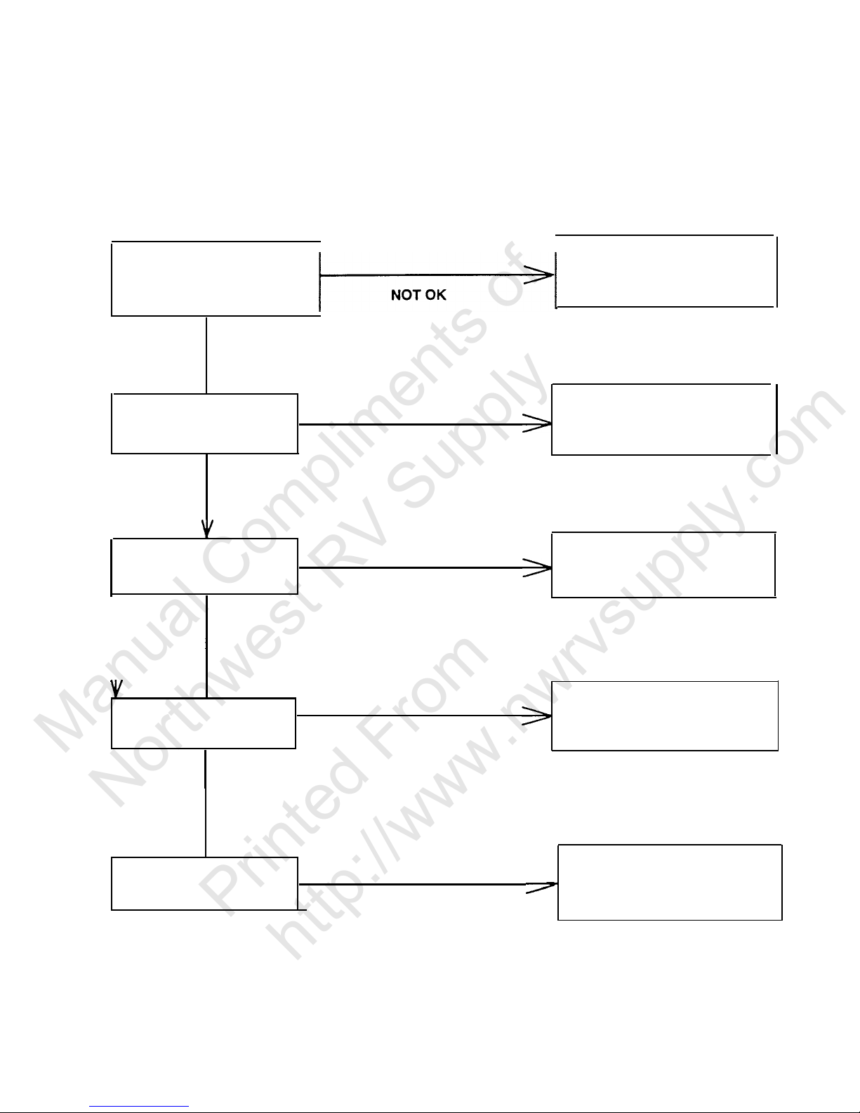
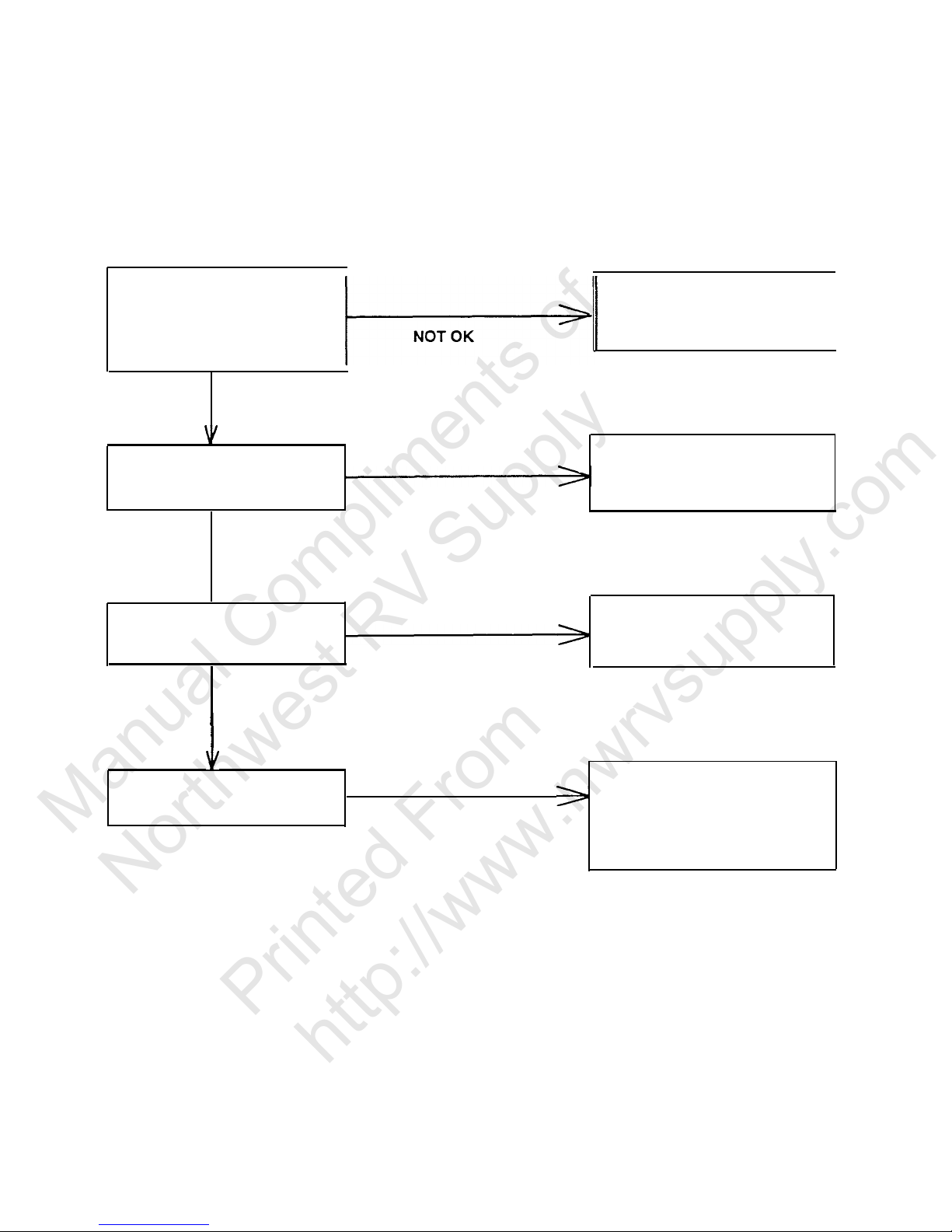
DIAGNOSTIC FLOW CHART
NO OPERATION
A.
1
Check Supply Voltage
1. 110 Volt Plug
2. Wire Size
Correct as Necessary
OK
B.
V
Check Fuse
Correct as Necessary
NOT OK
Replace if Defective
OK
.c.
Check wiring
Correct as Necessary
NOT OK
OK
D.
Check Switch
NOT OK
Correct as Necessary
(Page D-6-20,
Para.
66)
OK
E.
V
Check Thermostat
, Correct as Necessary
NOT OK
Continuity Check
D-4-l
Manual Compliments of
Northwest RV Supply
Printed From
http://www.nwrvsupply.com
Page 5
MANUAL REFRIGERATOR
DIAGNOSTIC FLOW CHART
NO 120 VOLT AC OPERATION
A.
1. Check AC Power
2. Refrigerator Plugged in
3. Breaker
4. Coach
Plug
Correct as Necessary
OK
B.
Check Selector Switch
NOT OK
Correct as Necessary
(Page D-6-20,
Para.
66)
OK
c.
V
Check Thermostat
Correct as Necessary
Continuity Check
NOT OK
OK
D.
Check 120 Volt Heater
NOT OK
Correct as Necessary
Ohm’s Reading
Bulletin
#28
(Page D-9-l 4, D-9-l 5)
D-4-2
Manual Compliments of
Northwest RV Supply
Printed From
http://www.nwrvsupply.com
Page 6
MANUAL REFRIGERATOR
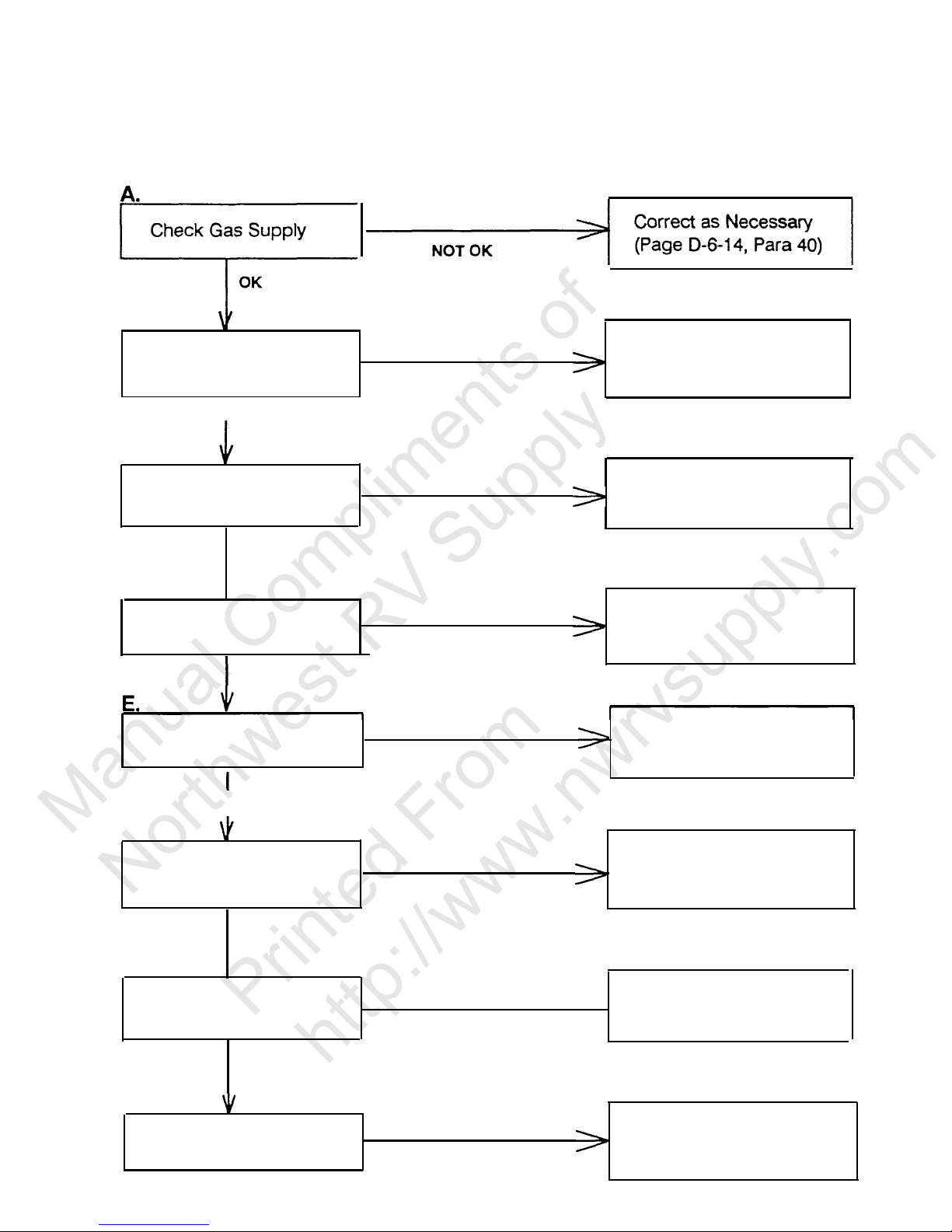
DIAGNOSTIC FLOW CHART
NO GAS OPERATION - Models Equipped with Piezo igniter
.
Check Gas Supply
OK
B.
Check Switch
I
NOT OK
Correct as Necessary
(Page D-6-20,
Para
66)
OK
.C.
Check Thermostat
OK
D.
V
Check Gas Pressure
OK
NOT OK
NOT OK
Correct as Necessary
Continuity Check
Correct as Necessary
(Page D-6-13,
Para.
37)
Check Flue & Burner
NOT OK
Correct as Necessary
No Obstructions
OK
F.
Check Piezo Resistance
I
NOT OK
Correct as Necessary
(Page D-6-l 8,
Para.
58)
OK
G.
V
Check Piezo Electrode
I
r
Replace Electrod
(Page D-6-18, 58)
NOT OK
OK
Check Spark Gap
Correct as Necessary
of Electrode to Burner
NOT OK
(Page D-6-19,
Para.
62)
D-4-3
Manual Compliments of
Northwest RV Supply
Printed From
http://www.nwrvsupply.com
Page 7
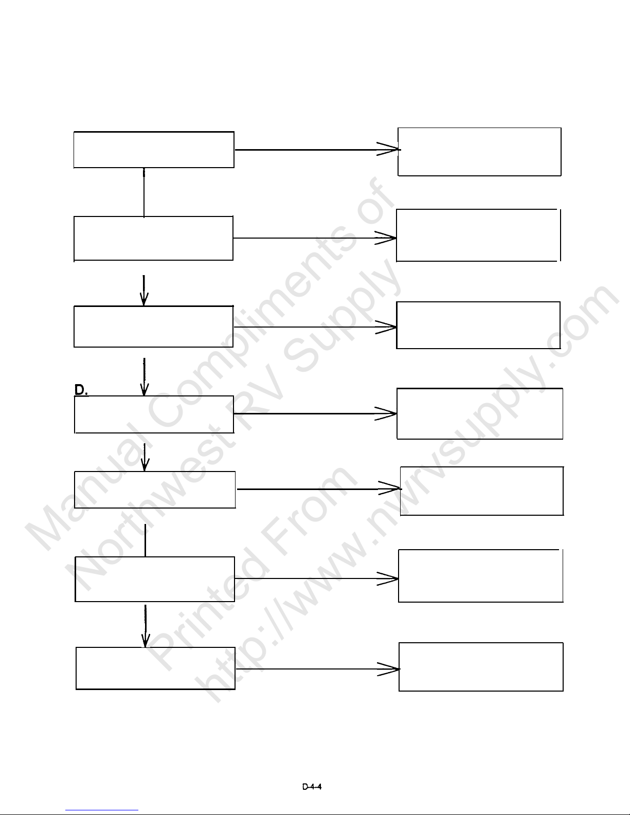
MANUAL REFRIGERATOR
DIAGNOSTIC FLOW CHART
NO GAS OPERATION - Models Equipped with Automatic Reigniter
A.
Check Gas Pressure
NOT OK
Correct as Necessary
(Page D-6-13,
Para
37)
OK
B.
V
Check Gas Supply
I
OK
NOT OK
Correct as Necessary
(Page D-6-14,
Para.
40)
C.
Check 12 Volt D.C.
Supply
Correct as Necessary
NOT OK
I
OK
Check Switch
NOT OK
Correct as Necessary
(Page D-6-20,
Para.
66)
I
OK
_E.
Check Thermostat
NOT OK
Correct as Necessary
Check for Continuity
OK
F.
V
Clean Assembly
&
Check Flue & Burner
Orifice as Necessary
NOT OK
I
OK
,G.
Check Electrode
Replace Electrode
(Page D-6-19,
Para.
62)
NOT OK
Manual Compliments of
Northwest RV Supply
Printed From
http://www.nwrvsupply.com
Page 8
NOTES:
D-5
Manual Compliments of
Northwest RV Supply
Printed From
http://www.nwrvsupply.com
Page 9

OPERATION & DIAGNOSIS
OF
DOMETIC
MANUAL REFRIGERATORS
D-6-1
Manual Compliments of
Northwest RV Supply
Printed From
http://www.nwrvsupply.com
Page 10
(1)
This is Dometic’s Manual Refrigeration Diagnosis and Troubleshooting program. In this program
we will discuss the way an absorption cooling unit operates, and the diagnostic procedures
used to troubleshoot the complete refrigerator system.
(2)
Before we begin extensive troubleshooting
procedures on the cooling unit, let’s take a few
minutes to see how it operates.
THE ABSORPTION SYSTEM
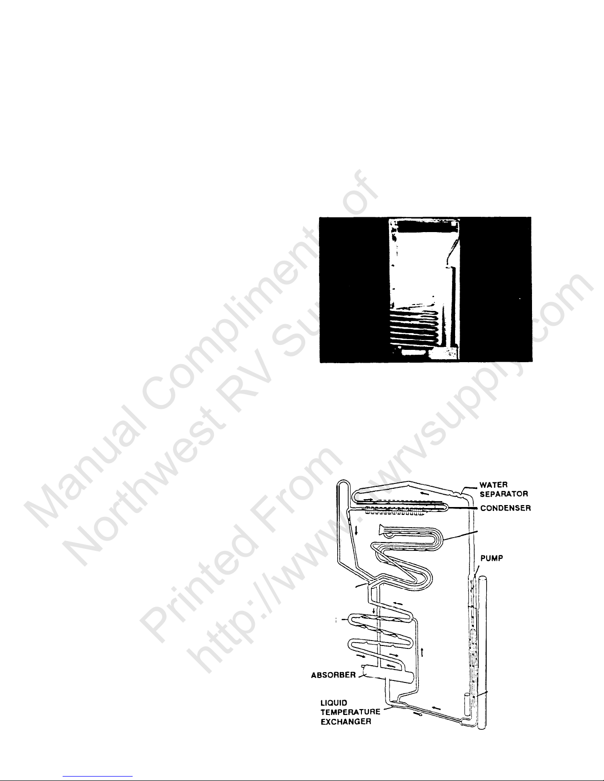
(3)
The sealed combustion unit contains a
mixture of ammonia, water and a rust
inhibiting agent. After this solution is
introduced into the coils, this unit is
pressurized with hydrogen gas. When
this system is in operation, the ammonia vaporizes in the hydrogen atmosphere and absorbs heat from inside
the refrigerator.
EVAPORATOR
GAS
TEMPERATURE
EXCHANGER
ABSORBER
VESSEL
BOILER
.
D-6-2
Manual Compliments of
Northwest RV Supply
Printed From
http://www.nwrvsupply.com
Page 11
(4)
The cooling unit parts that accomplish this
‘cooling’ or heat extraction process, include the:
Boiler or Generator
(5)
Condenser
(6)
Evaporator
PUMP
BOILER
l-------------
WATER
SEPARATOR
I
GAS
TEMPERATUR
EXCHANGER
------------
I
I
1
D-6-3
Manual Compliments of
Northwest RV Supply
Printed From
http://www.nwrvsupply.com
Page 12

(7)
Absorber
ABSORBER
THE ABSORPTION
SYSTEM
CONDENSER
EVAPORATOR
Because the self-contained cooling unit
does not utilize an electric compressor
or pump, the cooling coils can be operated from a variety of heat sources. LP
gas, 120 volts AC and 12 volts DC
heating elements are the most commonly used heat sources for recreational vehicle applications.
TEMPERATURE
EXCHANGER
TEMPERATURE
EXCHANGER
_
(9)
Before this cooling system can properly
extract heat from the cabinet of the
refrigerator, three requirements for proper refrigerator operation must be met.
These are precise heat, specified ventilation and proper leveling.
THREE REQUIREMENTS
FOR PROPER OPERATION
1. Level
2. Air Flow (Ventilation)
3. Heat
D-6-4
Manual Compliments of
Northwest RV Supply
Printed From
http://www.nwrvsupply.com
Page 13
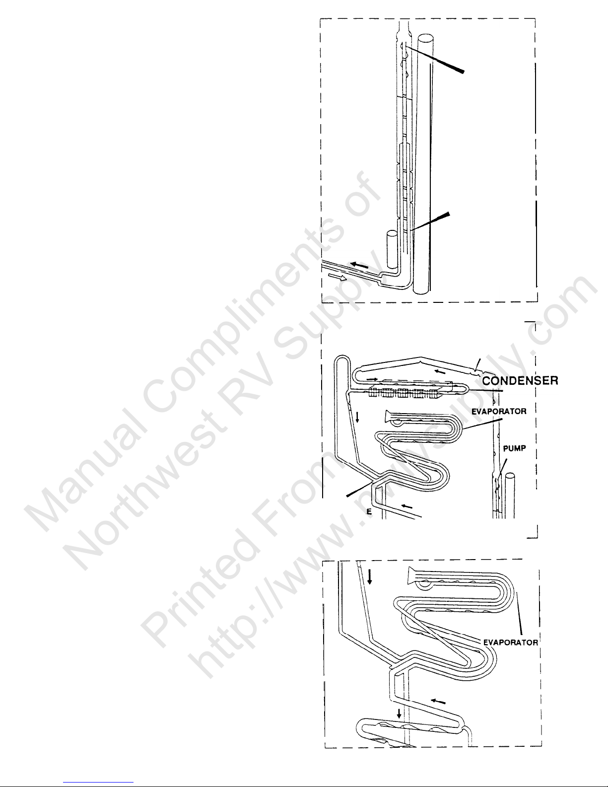
(10)
We will now take a closer look at how the
cooling unit functions in normal operation.
When proper heat is supplied to the boiler,
ammonia vapor is produced and rises in the
siphon pump, carrying with it a weak liquid
ammonia solution. As seen from this drawing,
the siphon pump, or pump tube, is an internal
arrangement within the boiler section. The boiler
section utilizes the ammonia-water liquid solution in the absorber and as it is heated, turns
the solution into a strong ammonia vapor, which
is needed to operate the system. This strong
ammonia vapor rises from the pump tube to the
condenser coil.
Any deviation from the listed amount of
heat to the absorption system will alter the
ammonia to water ratio, which, in turn, will
decrease the cooling unit’s overall efficiency.
The weak ammonia solution which remains
behind is diverted to the top of the absorber
coils to perform a function that we will discuss
in further detail later in the program.
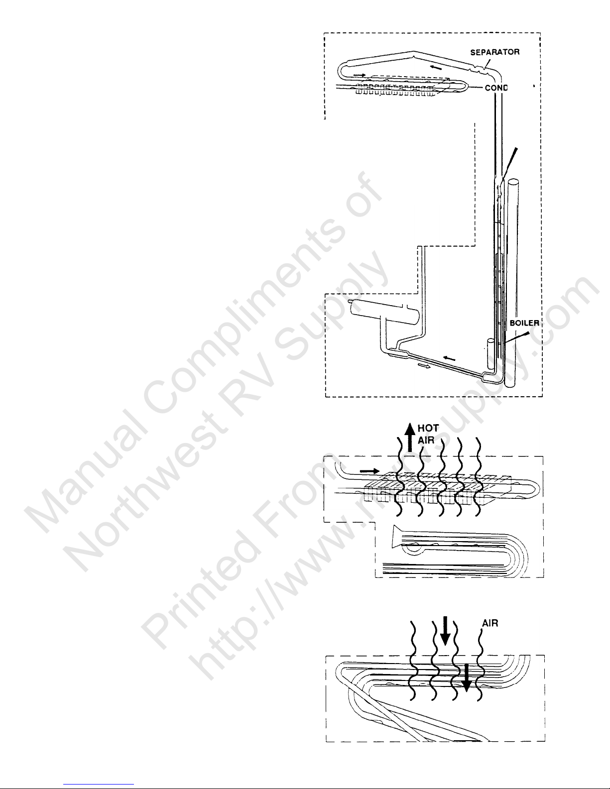
(11)
The air that passes through the condenser fins,
from the venting system, removes heat from the
ammonia vapor, causing it to condense into a
strong liquid ammonia solution. As a liquid, it
then flows to the low temperature evaporator, or
freezer companment, where it comes into
contact with a hydrogen atmosphere. When this
occurs, the ammonia begins to evaporate which
draws heat from inside the freezer section, to
the rear of the cooling unit.
(12)
This heat is then dissipated out through the
upper vent, which allows the refrigerators
interior temperature to properly maintain food
storage requirements. Not all of the liquid
ammonia evaporates in the freezer. What is left
continues to evaporate as it flows to the high
temperature evaporator, or food storage com-
partment.
WATER
I------------------------~
ENSER
PUMP
COLD INTERIOR
D-6-5
Manual Compliments of
Northwest RV Supply
Printed From
http://www.nwrvsupply.com
Page 14
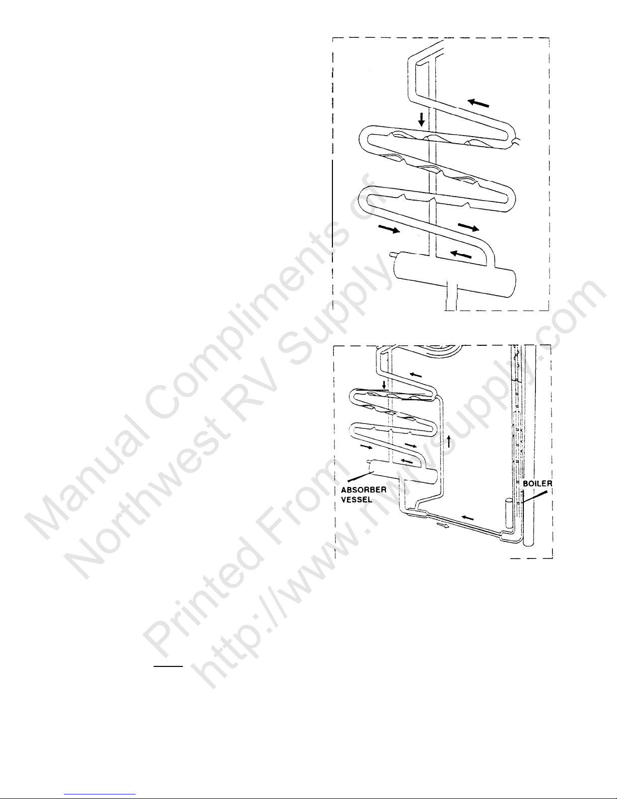
U
3)
As this process continues, the ammonia and
hydrogen vapors become intermixed and flow
downward into the absorber vessel. As the
ammonia vapor comes in close contact to the
liquid ammonia solution in the absorber vessel,
the ammonia is absorbed into the liquid
solution, allowing the hydrogen vapor to rise up
through the absorber coils. After this absorption
process, the vapor consists of mostly hydrogen
with some traces of ammonia.
-------
(14)
To remove the remaining amounts of ammonia
vapor still present in the hydrogen, a
continuous flow of weak ammonia solution is
fed, by gravity, to the top of the absorber coil
from the boiler. As this weak ammonia solution
flows downward through the absorber, it
absorbs the ammonia vapor from the mixture,
allowing the hydrogen vapor to rise through the
absorber coil and return to the evaporator. With
the hydrogen returned to the evaporator and
the ammonia remixed into solution in the
absorber vessel, the cooling process can
continue.
(15)
Now that we have a basic understanding of
proper cooling unit flow and operation, let’s
take a step-by-step look at the three require-
ments for proper cooling unit operation. Please
note it is essential that these three requirements
be diagnosed before attempting to diagnose
the cooling unit. A problem with leveling, heat
input or ventilation may lead you to think that
the cooling unit is faulty, when actually it is not.
This
causes an
increased expense to you, the
customer, and valuable shop time is wasted
because of incorrect diagnosis, By following
and checking the three unit requirements, costly
diagnostic errors can be eliminated.
---
__------
THREE REQUIREMENTS
FOR PROPER OPERATION
1. Level
2.
Air Flow (Ventilation)
3. Heat
D-6-6
Manual Compliments of
Northwest RV Supply
Printed From
http://www.nwrvsupply.com
Page 15
(16)
Since the absorption system utilizes no
mechanical pumps or compressors to circulate
the refrigerant within the system, proper leveling
is required to provide correct refrigerant flow in
the gravity-feed system. Without proper leveling,
refrigerant within the cooling coils will collect
and stagnate at certain areas. When this
happens the cooling process will stop.
(17)
On the older style cooling units equipped with
square boiler box covers, this condition can
cause permanent cooling unit failure. As we can
see from this drawing, square boiler box
cooling units utilize an exposed siphon pump
tube which will become excessively super-
heated in an out-of-level condition. This can
allow the rust inhibiting agent to chemically
break down and permanently block or restrict
the normal refrigerant flow through the pump.
Shaking, tipping or so called ‘burping the
refrigerator will not loosen or dislodge the
blockage. The only recommended service
procedure is to replace the cooling unit. To
prevent this occurrence, proper leveling is of
utmost importance when the RV is parked for
any length of time.
THREE REQUIREMENTS
FOR PROPER OPERATION
1.
Level
REFRIGERATOR IS TO BE LEVEL
(18)
To level these units, the spirit or bubble level
LEVELS
should be placed in the approximate front and
center of the floor of the freezer compartment.
The coach should then be positioned so that at
least 3/4 of the bubble is within the required
mark while the refrigerator is in operation.
REMEMBER: Failure to property
level
a square
boiler box can result in a lack of cooling or
permanent
damage to the coding unit. When
the vehicle is moving, leveling is not critical as
the rolling and pitching movement of the RV will
keep the solution in motion, preventing the
solution from accumulating in the piping.
--
-
D-6-7
Manual Compliments of
Northwest RV Supply
Printed From
http://www.nwrvsupply.com
Page 16
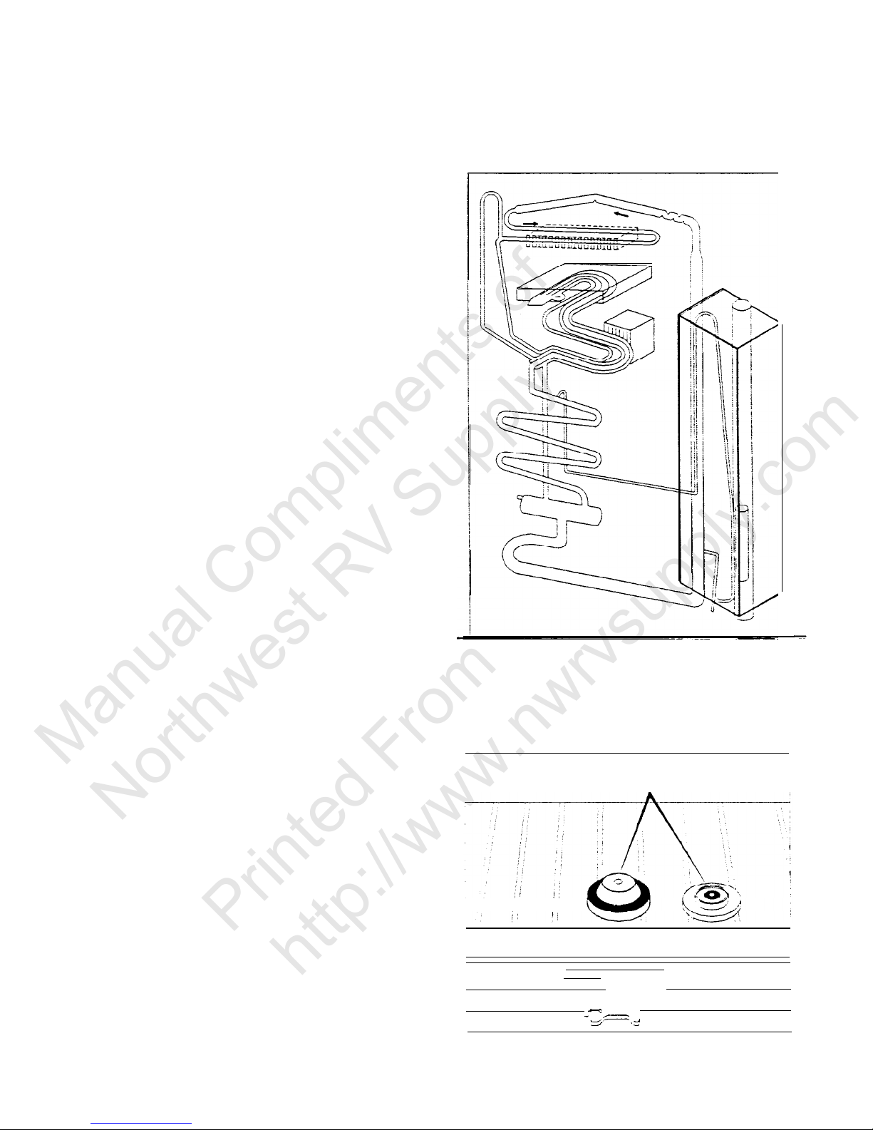
(19)
In recent years
Dometic
has engineered a new
type of cooling unit that utilizes an improved
siphon pump tube design which drastically
reduces the possibility of permanent damage to
the coils if operated in an out-of-level condition,
or too much heat is generated at the boiler
section. As we can see from this drawing, the
siphon pump tube is enclosed in the design
and is surrounded by a weak ammonia solution,
which will protect the pump tube from abnormally over-heating. This type of unit; however,
does not eliminate the need for proper leveling.
The unit still requires gravitational flow to
provide the proper cooling process, and if
leveling is outside the necessary limits, cooling
will dramatically slow down or stop completely.
The cooling coils are not normally damaged in
this fashion and once proper leveling is maintained, the cooling process will resume.
(20)
Spirit or bubble levels are no longer being
supplied with the new style refrigerators as the
RV or vehicle only needs to be leveled so it is
comfortable to live in, with no noticeable sloping
of the floor or walls. For diagnosis, the new
style
cooling
units that incorporate the
protection boiler system, can be differentiated
from the older style coils by the shape and
design of the outer boiler box cover on the rear
of the cooling unit. These units will incorporate
a circular metal cover,
. . .
while the older style utilizes a square
shaped enclosure.
We will discuss diagnosis
and troubleshooting of these units in more
detail later in the program.
PUMP
I
I
I
I
I
I
I
I
I
I
I
I
I
Manual Compliments of
Northwest RV Supply
Printed From
http://www.nwrvsupply.com
Page 17

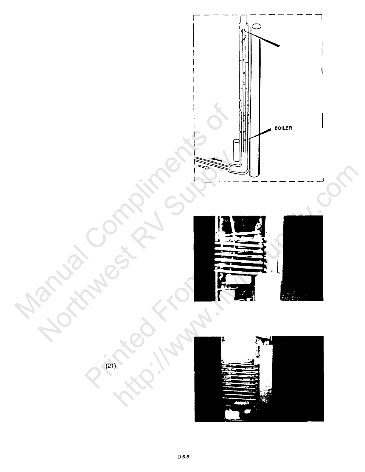
(22)
The coach vent system must be able to provide
a way to direct the hot air, produced by the
action of the cooling unit, out away from the
installation of the refrigerator.
(23)
In a good installation there should be as little
open space as possible surrounding the sides
and top of the refrigerator to achieve proper air
flow. All potential dead air pockets should be
blocked or baffled to insure that heat from the
cooling unit won’t be trapped in these spaces
and reduce efficiency. In addition, the cooling
unit should be at least one inch from the
nearest surface made of combustible materials.
Please follow the installation manual for proper
dimensions and clearances.
RVIA
requires that the refrigerator be
installed in such a manner as to provide
complete separation of the combustion system
and the interior atmosphere of the recreational
vehicle. This regulation requires all seams and
joints in the enclosure be sealed. The under-
counter installation is different. The addition of
a metal chute the width of the enclosure, that
extends from the upper side vent, will help
eliminate the possibility of dead air pockets. It
helps direct the hot air out the exhaust vent.
The best method for venting the absorption
refrigerator is with a lower side vent and a roof
vent. Using proper Dometic vents will give you
sufficient intake and exhaust areas for ventila-
tion
(24)
Heat application to the boiler section of the
cooling unit must be within the designed
BTU’s.
Never oversize the heating element on AC or
DC power source. Always use the proper size
orifice for gas modes. As explained earlier, any
deviation will cause a potential cooling unit
failure.
THREE REQUIREMENTS
FOR PROPER OPERATION
1. Level
2. Air Flow (Ventilation)
--------
----1
I
I
0"
CLEARANCE
1"
FROM
AIR FLOW
I
I
I I
------------
J
THREE REQUIREMENTS
FOR PROPER OPERATION
1. Level
2. Air Flow (Ventilation)
3. Heat
D-6-9
Manual Compliments of
Northwest RV Supply
Printed From
http://www.nwrvsupply.com
Page 18

(25)
Three things must be remembered
when diagnosing a cooling unit:
First, circulation within the cooling unit is totally gravitational. This
means proper leveling is important.
Second, heat - created to boil
the ammonia
-
now has to be dissipated into the surrounding air. Heat
from the absorber and condenser must
also be dissipated so as to cool the
ammonia sufficiently.
Third, proper heat application at
the boiler section.
THE ABSORPTION SYSTEM
(26)
When diagnosing a cooling unit, remember this
is the only part we cannot field check with test
equipment, yet it is the simplest and quickest
part to diagnose.
CONDENSER
EVAPORATOF
TEMPERATURE
EXCHANGER
BOILER
DIAGNOSING
THE
COOLING UNIT
(27)
After the unit has been operating for
approximately one hour, carefully touch the unit
at the boiler box and the absorber area. These
areas should be approximately the same
temperature, regardless
of the
ambient
temperature. Equal heat between the boiler and
the absorber indicates the fluid circulation within
the unit is good.
TEMPERATURE
GOOD CIRCULATION
D-6-10
Manual Compliments of
Northwest RV Supply
Printed From
http://www.nwrvsupply.com
Page 19

(28)
One of the faults with a cooling unit is
a blockage. This can happen when the
unit is operated off-ievel, or if too much
heat has been applied to the boiler
area. To the touch, this unit will be
extremely hot at the boiler with little
warmth at the absorber. In other words,
no circulation.
(29)
This type of fault means a lost charge.
It is known as a ‘leaker’. To the touch,
this unit will be warm at the boiler and
extremely hot at the absorber. In this
condition we are still boiling ammonia
but have no hydrogen for evaporation.
(30)
The following section of the program
examines the Dometic manual refrigerator’s gas and
electrical systems.
Dometic refrigerators are designed for
both piezo and automatic ignition. Both
systems will be covered in this presentation.
T
BOILER
HOT GAS ONLY
WARM
BOILER
D-6-1 1
Manual Compliments of
Northwest RV Supply
Printed From
http://www.nwrvsupply.com
Page 20

(31)
Let’s look at the current Dometic refrigerators
and see how the gas flows.
(32)
Gas flows from the gas line to the shut-off valve
and to the connection piece.
(33)
into the combination gas and electric thermostat
(34)
through the safety valve thermocouple
(35)
test housing
UNDERSTANDING
THE
GAS SYSTEM
SHUT-OFF
VALVE
I
GAS LINE
CONNECTION
PIECE
COMBINATION
GAS & ELECTRIC
THERMOSTAT
SAFETY VALVE/
PRESSURE
TEST
HOUSING
D-6-12
Manual Compliments of
Northwest RV Supply
Printed From
http://www.nwrvsupply.com
Page 21

(36)
and onto the orifice and burner assembly.
Remember that except
for the connection
piece,
all fittings are O-ring sealed. Whenever the
system is separated the O-rings must be
replaced.
ORIFICE & BURNER
ASSEMBLY
(37)
To diagnose the gas system, connect a
manometer to the test point. With the
thermostat on maximum you must have 11
inches water column pressure at this point. If
you have 11 inches pressure, your problem
Is to the right of the test point. If you do not
have 11 inches water column pressure, the
problem Is to the left.
(38)
Let’s take a closer look at the gas thermostat.
In this drawing we will review how a thermostat
functions. When the thermostat is working
properly, the manometer will read line pressure
when set at maximum and the refrigerator is
trying to cool. From this drawing you can see
the gas flow when the refrigerator is trying to
cool. The gas flows through the thermostat at
line pressure without restriction. The valve is
(39)
The valve is now closed and the gas must flow
through the by-pass screw; the gas is now
diverted through the by-pass screw, which
regulates the size of the low flame. This
condition can only exist when the refrigerator is
cold or the thermostat is set to minimum or off.
If the sensing tube has lost its pressure, even
with the thermostat set on maximum, you will
have only low flame.
DIAL SHAFT
open at this time.
VALVE
DIAL SHAFT
SCREW
CLOSED VALVE
D-6-13
Manual Compliments of
Northwest RV Supply
Printed From
http://www.nwrvsupply.com
Page 22

(40)
The most efficient way to diagnose the gas
system would be to first connect the gas
manometer to the pressure test point. With the
thermostat set at maximum you must have 11
to 12 inches water column pressure for the
refrigerator to operate properly. If your
manometer reads higher than 11 to 12 inches
water column pressure, the tank regulator is
adjusted to high, readjust it.
Make sure the
gas system has at least 50% of the coach’s LP
appliances on at the time the system is being
adjusted. If the manometer reads 11 inches, the
problem of no cooling lies in the burner
assembly, flue pipe or venting.
(41)
If you have less than 11 inches water column
pressure, the next step would be to remove the
by-pass screw.
NOTE:
The by-pass screw
reduces the pressure
and
volume of gas to the burner.
(42)
Shut off gas supply at the back of the refrigerator. Remove the by-pass screw from the top of
the thermostat,
Use a by-pass screw that does not have the
small O-ring at the bottom. Reinstall this by-
pass screw into the thermostat.
D-6-14
Manual Compliments of
Northwest RV Supply
Printed From
http://www.nwrvsupply.com
Page 23

Turn on the main gas supply and take a
reading. If the manometer now reads 11 inches,
the thermostat is defective and must be
replaced.
(45)
If the by-pass screw test shows no change in
gas pressure, the problem lies with the gas
supply to the refrigerator. Shut off the gas
supply, remove the by-pass screw, replace it
with one that has an O-ring and turn on gas
supply. Remember to check for a gas leak. At
this time we will take a look at the rest of the
gas system.
(46)
The safety valve, or flame
consists of a brass alloy
failure
safety
device,
valve housing and
cap, an electro-magnet, and a thermocouple,
which generates 14 to 30 millivolts when heat is
applied to the tip. It is used to energize the
electro-magnet in the safety valve. The purpose
of this device is to insure that the flow of gas is
shut off in the event flame is lost at the burner.
If this should occur, the thermocouple cools,
the magnet loses it magnetic field and the
valve closes. Most failures of this device are
related to the magnet, not the thermocouple.
Should this happen, the complete safety valve
should be replaced.
D-6-15
Manual Compliments of
Northwest RV Supply
Printed From
http://www.nwrvsupply.com
Page 24

(47)
Once the gas has been allowed to pass
through the safety valve, it flows to the gas jet
and burner. These have been specifically
designed to eliminate most of the normal maintenance required due to the corrosive contami-
nants in the gas, as well as soot and rust
which fall from the flue pipe. The jet has an
orifice made of an industrial ruby which has
been laser-beam drilled. Each model of
Dometic refrigerator uses a different size orifice
in order to maintain the required amount of
heat at the siphon pump. To clean the jet and
burner, soak them in an alcohol base solvent
and allow to air dry. DO NOT use a pin or
needle. This will distort or shatter the orifice.
(48)
If you determine that disassembly is required,
be aware there are two model designs for
manual refrigerators. The design pictured here
will be discussed first.
(49)
Shut off the main gas supply, then disconnect
at the back of the refrigerator. Remove the
cover over the thermostat and burner protection
cover at the right,
(50)
Now disconnect the 12 volts at the terminal
block and unplug the 120 volt cord. Remove
the two mounting screws on the left and pull
the metal locking arm out from under the
burner housing.
D-6-1
6
Manual Compliments of
Northwest RV Supply
Printed From
http://www.nwrvsupply.com
Page 25

(51)
The control assembly will now drop down and
can be pulled outward for service.
(52)
Pictured here is the other model design. Make
sure the main gas supply has been shut off
and disconnect the gas supply line at the
refrigerator.
I
(53)
Remove 3 screws on the burner cover plate.
The sheet metal assembly should now slide out
from the back of the refrigerator.
Remove the 2 screws from the plastic cover.
Also the 2 screws on the left and 2 screws on
the right of the metal bracket.
Manual Compliments of
Northwest RV Supply
Printed From
http://www.nwrvsupply.com
Page 26

There are 3 screws in the burner area that
must also be removed. Please note - these are
machine screws, not sheet metal type. It is
important for them to be reinstalled in this area
only.
(56)
The control assernbly will now drop down and
can be pulled out..,.,
fnr
On the present line of manual refrigerators we
use one of two methods of igniting the burner
flame. Shown on the right is the piezo system;
on the left is the igniter reigniter.
(58)
The piezo lighter is a self-contained assembly
which generalty -does not need maintenance.
When the button is ‘pushed, a spring loaded
striker creates a spark. If
there is
no resistance
when pressing the button, the
piezo
igniter is
defective and must be replaced. If the
piezo
snaps or has resistance when the button is
pushed, but there is no spark, the problem lies
in the electrode or electrode wire.
D-6-16
Manual Compliments of
Northwest RV Supply
Printed From
http://www.nwrvsupply.com
Page 27

The igniter reigniter, used on certain
Dometic
model refrigerators, operates on 12 volt current.
On gas operation the igniter senses the resistance through the flame between the electrode
and burner. When there is no flame at the
burner, the resistance is high and the igniter
begins sparking to light the burner. As soon as
the flame is lit, the resistance between the
electrode and burner drops and the igniter
stops sparking. The resistance is monitored by
the igniter, and, if for any reason the flame
goes out, the igniter begins sparking until the
burner is lit. This insures that the flame will
always be lit when desired. Each time the
igniter reigniter system sparks, a light will
illuminate on the lower left front corner of the
refrigerator.
If the electrode does not spark first, make sure
the igniter is receiving 12 volts. If the igniter is
receiving 12 volts and produces no spark, it
must be checked for operation.
(61)
Turn the refrigerator off and remove the wire
between the electrode and igniter. Now turn the
refrigerator to the gas mode. If no internal
clicking sound is heard the igniter is defective.
It is important to remove the high voltage wire
that goes to the electrode from the igniter when
you are checking the igniter for operation. The
high voltage wire and the electrode can be
shorted to ground causing the igniter reigniter
to think that the flame is lit, resulting in no
spark on gas operation.
(62)
The distance between the tip of the electrode
and the burner, known as the spark gap,
should be 3/16 of an inch. A greater distance
will create a slow spark causing the light to
blink. A lesser distance will create a fast spark
that may not light the burner.
Burner
SPARK GAP
D-6-19
Manual Compliments of
Northwest RV Supply
Printed From
http://www.nwrvsupply.com
Page 28

(67)
Before an appliance can be sold to a recrea-
tional vehicle manufacturer it must be tested
and approved by a nationally recognized
testing laboratory for the specific end use
intended.
All Dometic refrigerators used in
recreational vehicles have received this certifica-
tion.
If you require additional service assistance on
the basic requirements for the cooling unit
operation or the manual refrigeration, please
refer to the diagnostic manual. For additional
technical service assistance, contact the
Technical Service Department at (219)
463-
4858.
(69)
You are an essential part of a team that contributes greatly to the successful future of the
RV industry, your dealership and
Dometic.
Thank you for participating in the training
program.
D-6-21
Manual Compliments of
Northwest RV Supply
Printed From
http://www.nwrvsupply.com
Page 29

NOTES:
D-7
Manual Compliments of
Northwest RV Supply
Printed From
http://www.nwrvsupply.com
Page 30

Glossary of Terms
MANUAL REFRIGERATION
1.
ABSORBER: Section of the cooling unit where the hydrogen and ammonia vapor are intermixed
in the absorber. Ammonia vapor returns to solution and the hydrogen returns to the
evaporator.
2.
BOILER:
Section of the cooling unit where heat is applied. This is where the ammonia is
partially separated from the water.
3.
BY-PASS SCREW: Small brass screw located on any
Dometic
gas thermostat that regulates gas
flow in the low flame mode. There are three common sizes of this screw: S-17-350 BTU, S-
14-325 BTU, S-l l-300 BTU.
4.
Found on current
Dometic
manual GAS/ELECTRIC THERMOSTAT:
refrigerators, this device is held in place with "0"" ring seals in the gas line and replaces
separate electric and LP gas thermostat controls. On the LP gas mode, full line pressure is
directed through the thermostat to the burner until the thermostat senses that the
refrigerator cabinet has reached proper cooling temperature. At that rime an internal valve
closes and redirects the gas flow through the by-pass screw. This reduces the amount of LP
gas going to the burner assembly. The gas flow remains in this “by-pass” mode until the
thermostat senses that the refrigerator cabinet needs more cooling. Again, the thermostat
directs the LP gas flow through the thermostat at full line pressure until the cabinet
temperature is sufficient. On the electric mode the internal mechanism breaks contact
(continuity) when adequate cabinet temperature has been reached.
5.
CONDENSER:
Section of the cooling unit that cools the ammonia vapor into ammonia liquid.
6.
COOLING UNIT: Self-contained, hermetically sealed set of steel coils where the refrigeration
process takes place. The chemicals involved in the cooling process include hydrogen,
ammonia, water and a rust inhibiting agent.
7.
CUT-OFF VALVE (Shut-Off Valve): Valve where the incoming propane supply is attached.
This valve is direct-coupled to the selector switch by means of a steel clip. When the selector
switch is turned to the electric mode, the cut-off valve is automatically closed. When this
same switch is turned to the LP gas mode, the electric circuit is also automatically
interrupted.
8.
EVAPORATION:
A process that causes a liquid to turn into a vapor. Whenever evaporation
takes place, heat is removed.
9.
EVAPORATOR:
Section of the cooling unit where the cooling effect is produced. Liquid
ammonia evaporating in a hydrogen atmosphere takes place in the evaporator.
10.
HEATING ELEMENTS:
Elements that operate off either AC or DC voltage that create heat to
the cooling unit.
11.
IGNITER-REIGNITER:
The igniter-reigniter, used on certain
Dometic
model refrigerators,
operates on 12 volt current. On gas operation the igniter senses the resistance through the
flame between the electrode and burner. When there is no flame at the burner, the resistance
is high and the igniter begins sparking to light the burner. As soon as the flame is lit, the
resistance between the electrode and burner drops and the igniter stops sparking. The
resistance is monitored by the igniter, and if for any reason the flame goes out, the igniter
begins sparking until the burner is lit. This insures that the flame will always be lit when
desired. Each time the igniter-reigniter system sparks, a light will illuminate on the lower
left front corner of the refrigerator.
12.
L.P. GAS PRESSURE: For the refrigerator to operate properly on LP gas, the gas pressure
should be set at 11” water column pressure.
NOTE: use the test port at the rear of the
refrigerator to take this reading.
D-8-1
Manual Compliments of
Northwest RV Supply
Printed From
http://www.nwrvsupply.com
Page 31

(Glossary of Terms . . continued)
13.
14.
15.
16.
17.
18.
ORIFICE
(JET):
A small brass fitting that is mounted on the gas line just prior to the burner.
This device incorporates a very small opening to greatly reduce gas flow to the burner. The
orifice is cleaned by using an alcohol based solvent and allowing to air dry.
PIEZO LIGHTER: Self-contained lighter assembly that is used to generate a spark to light the
refrigerator on LP gas. This unit contains a quantity of quartz crystals that when pushed or
snapped, produce a spark. There are no serviceable parts on this device.
SAFETY DEVICE: An assembly of parts (safety valve, magnet and thermocouple) that shuts off
the supply of LP gas to the burner assembly if the flame goes out for any reason. This is to
ensure that a concentration of unburned gas does not accumulate in the refrigerator vent
area.
SELECTOR SWITCH: This is also a circuit interrupter on the 12 volt DC, 120 volt AC and gas
sides of operation on the refrigerator. When the customer selects either DC, AC or GAS
operation, the selector switch directs electricity first to the thermostat and on to the heating
element, or igniter-reigniter. When this switch is turned off, the AC or DC circuit is
interrupted.
SPIRAL BAFFLE: Spiral metal device that is hung in the flue tube assembly of the cooling unit.
The baffle causes the heat supplied by the gas burner to stay at the boiler assembly a longer
period of time. This allows the absorption system to work as efficiently on LP gas as other
heat sources.
WATER COLUMN: The pressure rating given to LP gas line pressure. Usually this pressure can
be varied by adjusting the regulator on the LP supply tank. A manometer is the device used
to test LP gas pressure.
D-8-2
Manual Compliments of
Northwest RV Supply
Printed From
http://www.nwrvsupply.com
Page 32

TYPES OF BLOCKAGE
To understand the absorption principle we have set up several refrigerators to inspect and diagnose.
Carefully touch the absorber and boiler sections of each unit and record your findings. Proceed with
caution as some of these units could be extremely
HOT.
Listed below are three types of units you will be testing:
q
GOOD COOLING UNIT
Carefully touch the unit at the boiler box and the absorber area. These areas
should be approximately the same temperature, regardless of the ambient
temperature. The equal heat between the boiler and the absorber indicates the
fluid circulation within the unit is good.
BLOCKAGE
One of the faults with a cooling unit is blockage. This can happen when the unit
is operated off-level, or if too much heat has been applied to the boiler area. To
the touch this unit will be extremely hot at the boiler with little warmth at the
absorber. In other words, NO CIRCULATION.
LEAKER
This type of fault means the unit has lost its charge - it’s known as a “leaker”. To
the touch this unit will be warm at the boiler and extremely hot at the absorber.
In this condition we are still boiling ammonia but have no hydrogen for
evaporation.
D-9-l
Manual Compliments of
Northwest RV Supply
Printed From
http://www.nwrvsupply.com
Page 33

CHANGING THE
HINGE POSITION
q
Refrigerator
Bulletin R54/7A
March 1987
R54/7A
MODELS:
2600,2602,2800,2802,
3600,3601,3800
& 3801
I
WHEN
CHANGING
THE HINGE POSITION:
Insure that the door latch assembly operates
properly after changing the hinge position from
left to right, or vice-versa, with the following
checks:
A. The refrigerator door(s) opens and closes
easily.
B.
The door gasket seals smoothly and completely
on all sides.
C. Slide the latch left to the locked position
and try to open the door(s).
The latch
assembly should keep the door(s) from opening.
NOTE: A
hard
pull will release the door
latch assembly and the door(s) will
open.
This is not a fault.
(If
an
adjustment
is
required,
repeat the
above
procedure to determine the
effectiveness of the repair.)
SMOOTH FIT,
PROPER SEAL
SMOOTH FIT,
FIG. 1
P
ROPER SEAL
If the door(s) open when the latch assembly
is in the locked position, adjust the hinge/door
assembly. Follow the outlined steps to complete
this procedure:
1.
Open the door and remove the two (2)
front decoration screws located underneath
the upper hinge assemblies.
2.
Remove the front decoration by lifting
the decoration upward.
D-9-2
FIG. 2
3.
4.
FlG.
3
Loosen the screws that hold the upper
hinge in place.
Reorient the door so the catch retainer
on the door will engage with the latch
assembly. (Usually lowering the door
will accomplish this.)
MOVABLE
Manual Compliments of
Northwest RV Supply
Printed From
http://www.nwrvsupply.com
Page 34

(Bulletin R54/7A continued)
5.
Hold the door in its new position and
carefully
retighten
the hinge screws,
being careful not to change the hinge
position.
6.
Close the door and again determine if
the latch is now operational.
7.
If more adjustment of the door position
is
necessary,
the center hinge screws
may be loosened to reorient the door in
the proper position.
8.
Again retighten the hinge screws to
allow the latch to operate properly.
SPECIAL
HINTS TO ADJUST DOOR
1.
If there is a large distance between the lower door
catch retainer
and the latch,
adjusting
the hinge
position still may not allow the latch to operate properly.
LATCH
FIG. 5
EXCESSIVE
GAP
2.
Remove the upper, and if necessary, the center hinge
pin(s).
This allows you to remove the refrigerator
door(s).
3.
Place a metal,
1/4"
flat washer (available at any
hardware store) over the lower hinge pin and reinstall
the
door(s).
This will raise the door to engage the
latch assembly. (On very rare occasions two
[2]
washers
may be required.)
If the latch assembly still will not engage, the base can
be repositioned to reorient the door as follows:
1.
Turn the refrigerator on its side to gain access to the
four (4) base screws. Loosen all four (4) screws slightly.
2.
Reposition the base so that the door catch retainer
engages with the latch.
3.
Retighten the base screws
while
holding
the base in
its new position.
By following the above listed procedures you will be able
to correct any door latching problems incurred when
reversing the hinge position on your
Dometic
refrigerator.
If you have any questions concerning
contact our Technical Services Department at:
DOMETIC
SALES CORPORATION
509 South Poplar St.
LaGrange,
IN 46761
this procedure,
FIG. 7
BASE SCREWS
D-9-3
Manual Compliments of
Northwest RV Supply
Printed From
http://www.nwrvsupply.com
Page 35

PROCEDURE FOR
CHANGING COOLING UNIT
The following categories have been established
predicated on similarity of design and procedure
for replacement of cooling units. Most
Dometic
refrigerators are covered in one (1) of these
categories.
SPECIAL NOTE: After the cooling unit has been
installed, the initial
start-up
time can be
shortened by tilting the refrigerator from side
to side and then from front to back before the
refrigerator is turned on.
TILT SIDE-TO-SIDE
Run the refrigerator on a bench for 12 hours
after the cooling unit has been installed (all
food should be removed for testing).
Refrigerator
Bulletin
R55/7A
April 1987
6
WOOD BLOCK
FIG. Al
2
FIG. A2
\I
FC140
Cooling
Unit cannot be replaced
A. Category
#l
RM46
RM46 1
RM663
RM2500
RM360
RM660
RM2300 RM3500
RM460
RM661
RM2400
REMOVAL OF COOLING UNIT
1.
2.
3.
4.
5.
6.
Remove heater(s) from boiler case (FIG. Al).
Disconnect burner from chimney (FIG. A2).
Remove evaporator screws inside refrigerator
and remove cooling flange (FIG. A3).
Remove screws holding clamp for capillary
tube.
Pull capillary gently out of plug (FIG.
A3).
Remove screws
Al).
Apply leverage
Al).
holding unit from rear (FIG.
as shown and pull out (FIG.
FIG. A3
D-9-4
Manual Compliments of
Northwest RV Supply
Printed From
http://www.nwrvsupply.com
Page 36

(Bulletin
R55/7A
continued)
INSTALL REPLACEMENT COOLING UNIT:
1.
2.
3.
4.
5.
6.
7.
Trim the Styrofoam portion of the cooling
unit if
it does not go freely into the
refrigerator.
Apply sealing permagum (sealing tape) on
mounting plate (A; FIG. A4).
Apply thermal mastic on the evaporator coil
(B; FIG. A4).
Tighten screws securely to obtain proper
contact between the evaporator coil and
evaporator flange; otherwise improper cabinet
performance may result.
Install the heating element completely back
into the pocket and plug in.
Reconnect burner assembly to chimney.
Reinstall capillary tube into proper position
(FIG. A3).
FIG.
A4
B. Category #2
RM100
RM763
RM1303
RM760
RM1300
RM2600
RM3600
RM76
1
RM1301
RM2800
RM3800
REMOVAL OF COOLING UNIT:
1.
2.
3.
Remove screw holding clamp for capillary
tube.
Pull capillary tube out gently and
place aside (FIG.
Bl).
a.
RM3600, RM3800 (FIG. B4)
Remove heater(s) from boiler case (FIG.
Bl).
Disconnect burner from chimney (FIG. B2
and B3).
a.
RM2600,
RM2800,
RM3600,
RM3800
(FIG. B3).
D-9-5
4.
Remove
evaporator screws (FIG.
B4).
5.
Remove screws holding unit from rear (FIG.
Bl).
6. Cut tape holding plate (FIG.
B1).
7. Apply leverage as shown and pull unit out
(FIG. B
).
5
6
WOOD BLOCK
FIG.
B3
FIG. 84
INSTALL REPLACEMENT COOLING UNIT:
1. Trim the Styrofoam portion of the cooling
unit if
it does not go freely into the
refrigerator.
Manual Compliments of
Northwest RV Supply
Printed From
http://www.nwrvsupply.com
Page 37

(Bulletin R55/7A) continued)
2.
3.
4.
5.
6.
7.
Apply sealing permagum (sealing tape) on
mounting plate (A; FIG.
B5).
Apply thermal mastic on the evaporator coil
(B; FIG.
B5).
Tighten screws securely to obtain proper
contact between the evaporator coil and
evaporator flange;
otherwise improper cabinet
performance may result.
Install the heater element completely back
into pocket and plug in.
Reinstall capillary tube into proper position.
a.
RMl00,
RM2600 & RM2800 will clamp to
cooling flange. (FIG. B4)
b.
RM760, RM761 & RM763 will extend into
retainer tube approximately 31” (FIG .
Bl)
C.
RM1300, RM1301 ` RM1303 will extend
into retainer tube approximately 36”
(FIG.
Bl)
d.
RM3600
&
RM3800 have internal thermostat
with capillary tube clamped to cooling
flange (FIG. B4)
Reconnect the burner assembly to chimney.
SEALING PERMAGUM
FIG.
B5
C. Category
#3
RC150
RC160
REMOVAL OF COOLING UNIT:
1. Remove screw and disconnect burner
chimney (FIG. Cl).
2. Disconnect heater wires from terminal
(FIG. Cl).
from
block
a.
Remove heaters from boiler case (FIG. Cl).
D-9-6
3.
4.
5.
6.
7.
Remove screws holding unit from rear (FIG.
Cl).
Disconnect green grounding wire (FIG. Cl).
Pull out on cooling flange to remove
fr
evaporator coil (FIG. Cl).
Pull thermostat capillary tube out gently and
move so that cooling unit will clear (FIG. Cl).
Remove cooling unit by hinging out on right
side (FIG. Cl).
INSTALL REPLACEMENT COOLING UNIT:
1.
2.
3.
4.
5.
6.
7.
Trim the Styrofoam portion of the cooling
unit if it does not go freely into the
refrigerator.
Apply sealing permagum (sealing tape) on
window insulation (A; FIG. C2).
Apply thermal mastic on the evaporator coil
(B; FIG. C2).
Tighten screws securely to obtain proper
seal; otherwise improper cabinet performance
may result.
Install the heat elements completely back
into the pocket and attach to terminal block
(FIG. Cl).
Reconnect burner assembly to chimney (FIG.
Cl).
Reinstall capillary tube into proper position
(FIG. Cl).
SEALING PE
(Sealing
(A)
FIG. C2
Manual Compliments of
Northwest RV Supply
Printed From
http://www.nwrvsupply.com
Page 38

(Bulletin
R55/7A
continued)
D. Category
#4
RM190
RM2190
RM2 192
REMOVAL OF COOLING UNIT:
1.
2.
3.
4.
5.
Remove cover and flue tube, then disconnect
burner from chimney (FIG.
D1).
Remove heater(s) from boiler case (FIG.
Dl).
Remove screws and take out evaporator fins
and shelf (FIG. D2).
Release holding clamp for thermostat capillary
tube and pull tube out gently (FIG. D2).
Remove one (1) screw and bend two (2) tabs
and then pull cooling unit out (FIG.
Dl).
FIG.
D1
INSTALL REPLACEMENT COOLING UNIT:
1.
Trim the Styrofoam portion of the cooling
unit if it does not go freely into the
refrigerator.
2. Apply thermal mastic on the evaporator coil
(B; FIG. D3).
D-9-7
3.
4.
5.
6.
7.
Apply sealing permagum (sealing tape) on
window
insulation
(A; FIG. D3).
Tighten screws securely to obtain proper seal.
Install the heating elements completely back
into the pocket.
Reinstall capillary tube into proper position.
Reconnect burner assembly to chimney and
replace cover.
FIG. D3
E. Category
#5
REMOVAL
OF COOLING UNIT:
1.
2.
3.
4.
Remove
chimney
Remove
Remove
rear (FIG. E 1).
cover and disconnect burner
from
(FIG. El).
heater from boiler case (FIG. El).
three (3) screws holding unit from
Pull cooling unit part way out and then
disconnect thermostat capillary tube and pull
out
(1;
FIG. E2).
5.
Complete removal of cooling unit.
6.
Remove evaporator fins and shelf (2; FIG. E2).
A)
SEALING
PERMAGUM
(Sealing
Tape)
RM211
INSTALL REPLACEMENT COOLING UNIT:
1.
2.
3.
4.
5.
6.
7.
Apply thermal mastic on the evaporator coil
(B; FIG. E2).
Install evaporator fins and shelf (FIG. E2).
Apply sealing permagum (sealing tape) on
window insulation (A; FIG. E2).
Reinstall capillary tube into proper position
(FIG. E2).
Tighten screws securely to obtain proper
sealing.
Reconnect burner assembly to chimney and
replace cover (FIG. El).
Install the heating elements completely back
into the pocket (FIG. El).
Manual Compliments of
Northwest RV Supply
Printed From
http://www.nwrvsupply.com
Page 39

(Bulletin
R55/7A
continued)
3
FIG. El
(A)
SEALING
PERMAGUM
(Sealing Tape)
FIG. E2
F.
Category
#6
3
RM75
RM76
RM77
REMOVAL OF COOLING UNIT:
1.
2.
3.
3.
5.
Remove burner protection cover and remove
burner from chimney (FIG.
Fl).
Remove heaters from boiler case (FIG.
Fl).
Remove evaporator screws (FIG. F2).
Remove two (2) screws holding clamp for
thermostat
capillary
tube.
Pull capillary
tube out gently (FIG. F2).
Remove ten (10) screws holding unit from
rear (FIG.
Fl).
6.
Pull out on cooling unit and remove.
5
2
5
INSTALL REPLACEMENT COOLING UNIT:
1.
3
_.
3.
Trim the Styrofoam portion of the cooling
unit
if it does not go freely into the
refrigerator.
Thermal mastic is not used on these units.
Apply sealing permagum (sealing tape) on
mounting plate (FIG. F3).
FIG.
F1
D-9-8
Manual Compliments of
Northwest RV Supply
Printed From
http://www.nwrvsupply.com
Page 40

(Bulletin
R55/7A
continued
4. Tighten screws securely to obtain proper seal.
5.
Install heating elements completely back into
the pocket and plug in (FIG.
Fl).
6. Reconnect burner assembly to chimney (FIG.
Fl
).
7. Reinstall capillary tube into proper position
(FIG. F2).
FIG. F3
REMOVAL OF COOLING UNIT:
1.
2.
3.
4.
5.
6.
Remove six (6) screws from burner cover
(FIG.
Gl).
Disconnect burner from chimney (4 screws)
(FIG.
Gl).
Remove heaters from boiler case (FIG.
G1).
Carefully pull out thermostat capillary tube
(FIG.
G1).
Remove two
(2)
evaporator screws and take
out ice tray support (FIG. G2).
Remove eight (8) screws holding unit from
rear (FIG.
G1).
Remove
two (2) screws holding gas line
gasket (FIG.
Gl).
6
/
l THERMAL MASTIC IS NOT USED
G.
Category
#7
RM182
5.
6.
7.
Tighten screws securely to obtain proper seal.
Install the heating elements completely back
into the pocket.
Reconnect burner assembly to chimney and
replace cover.
FIG.
G1
FIG.
G2
INSTALL REPLACEMENT COOLING UNIT:
1.
2.
3.
4.
Trim the Styrofoam portion of the cooling
unit if
it does not go freely into the
refrigerator.
Apply thermal mastic on the evaporator coil
(B; FIG. G3).
Apply sealing permagum (sealing tape) (A;
FIG. G3).
Reinstall thermostat capillary tube.
D-9-9
(A
SEALING PERMAGUM
(Sealing
Tape)
FIG. G3
Manual Compliments of
Northwest RV Supply
Printed From
http://www.nwrvsupply.com
Page 41

Before You Change
That
Cooling Unit
PART I. PROPER DIAGNOSIS
Cooling units are sometimes diagnosed as being
defective when the actual problem is something
else.
Cooling units are expensive to replace, so
it is important to make the correct diagnosis. By
using the proper test procedures, you can eliminate
all other possibilities before condemning the
cooling unit.
Any time the cooling unit is a possible suspect,
use the following step-by-step procedure before
replacing it.
A.
1.
2.
3.
4.
PRELIMINARY
CHECKS
Check for an ammonia smell around the
cooling
unit and
inside
the refrigerator.
This could indicate a possible refrigerant
leak.
Check for any deposits of yellow
powder on the tubing which will sometimes
form around the area of a leak. NOTE: A
yellow deposit in the area of the fill valve
could be due to splashing of refrigerant
during manufacture,
and would not indicate
a leak.
Determine if the refrigerator works on one
heat source but not another by testing it in
the alternate modes. Also, ask the customer
if he gets better cooling results from one
energy source than another. If this is true,
it indicates the problem is
NOT
in the cooling
unit.
Make sure the refrigerator is level. Sometimes
the vehicle is level but the refrigerator is
not, due to improper installation.
Place a
level on the bottom of the freezer compartment and check side-to-side and front-to-back
levels (see FIG. Al).
Use a mirror, if
necessary to read the level.
Carefully check door gaskets for proper
seal.
A leaking gasket can allow enough
warm air inside the refrigerator to overcome
most of the cooling being produced.
D-9-l
0
REFRlGERATOR
BULLETIN
R61/7A
DEC.
1987
For a simple method to check gaskets, close
the door on a dollar bill, then pull the dollar
bill out.
If no resistance is felt, the gasket
is not sealing properly.
This should be done
on all four sides of the door.
FIG. Al
CHECK
LEVEL
BOTH
WAY.
5.
Check the venting system to insure that
ample air flow is provided at the back of
the refrigerator.
A. Check for, and remove, any restrictions
in the vents, such as filters installed by
the customer, bird nests in the roof
vent,
or smashed louvers in the wall
vents (see FIG. A2).
B.
Make sure the correct roof vent has
been installed.
Larger models such as
RM100, 760, 761, 1300, 1303, 2600, 2800,
2802, 3600, 3800, 3802 and 4801, require
a 5” X 24” opening for the roof vent
Smaller models will also use the
5”
24” roof opening. To check this, measure
the actual opening in the roof - DO
NOT measure the roof vent itself.
See
FIG. A2.
Manual Compliments of
Northwest RV Supply
Printed From
http://www.nwrvsupply.com
Page 42

(Bulletin continued)
FIG.
A2
Also,
make sure the distance from
the bottom of the refrigerator to the
roof
vent is
at least the minimum
dimension
given
in
the Installation
Instructions for each model.
See FIG.
A2.
FOR MINIMUM
DIMENSION.
SEE INSTALLATION
INSTRUCTIONS
MIN. 5
C.
MAXIMUM OPEN
SPACE 1
1/2
IN.
(See 5D)
CHECK FOR RESTRICTIONS
IN AIR DUCTS OR VENTS
(See
5A)
Some smaller models may be installed
with two side wall vents instead of
using a roof vent.
For this type of
installation make sure the top of the
upper vent is the correct distance above
the refrigerator.
See FIG. A3.
The
minimum dimension for this measurement
is listed in the Installation Instructions
for each model.
FIG. A3
CHECK MINIMUM
HEIGHT (See
Installation
Instructions)
D. Check the open space above the refrigera-
tor. If this space is 1
1/2
inches or
more it must be blocked off to prevent
hot air from being trapped above the
refrigerator. See FIG. A2.
If venting is suspected as a problem, run the
performance test described below with
the refrig-
erator installed, then run the same test with
the refrigerator removed. If there is a definite
improvement in performance, a venting problem
is indicated.
Also, see Section B. PERFORMANCE
TEST, Item 9.
L
D-9-1 1
SPECIAL VENTING FOR DIRECT-VENT MODELS
RM
182, 215, 2192
These models are designed to be installed in
small vans and are usually placed in a cabinet
that is not open to the outside of the vehicle.
This means that air from within the vehicle
must be used to cool the condenser.
Customers with this type of installation must be
made aware that the vehicle interior must be
kept from getting too hot.
If the vehicle is
left parked in the sun, with all doors and windows
closed, the inside temperature can quickly exceed
100 degrees,
and the cooling process will slow
down or stop completely.
REAR VIEW OF REFRIGERATOR
Arrows indicate direction
Alternative positions
SIDE VIEW OF
upper
ventilator
Arrows indicate
direction
of air flow over Cooling
Unit
Lower
Ventilator
Manual Compliments of
Northwest RV Supply
Printed From
http://www.nwrvsupply.com
Page 43

[Bulletin
R61/7A
continued)
B.
1.
3
3.
4.
PERFORMANCE
TEST
First perform
all the preliminary
checks
described previously.
Remove all food from the refrigerator and
place all controls in the OFF position.
Place an accurate thermometer in an ice
cube tray, half filled with water, and place
the tray in the center of the lower food
storage compartment. NOTE: If a
remote-
reading thermometer
is
used (allowing
temperature readings without opening the
door) the tray of water is not required.
Make sure the AC heating element is the
correct wattage for the model being tested,
and that the resistance reading is correct.
(See
“Checking Resistance of a Heating
Element” below.)
Connect 120 volt AC power directly to
the heating element leads (make sure the
leads are not connected to the refrigerator
circuit),
then check
the voltage at the
element with a volt meter.
Reading must
show at least 115 volts.
CHECKING RESISTANCE OF A HEATING
ELEMENT
A simple test to check a heating element is to
measure
the resistance through
the element
with an ohmmeter.
The correct resistance, in
ohms,
can be calculated if the wattage and
voltage ratings are known.
(These ratings are
stamped on all
Dometic
heating elements.)
Use this Formula:
Volts (Watts Volts) = Ohms
Example:
Heating element rated 135 Watts at 110 Volts.
110 (13.5 110) or,
110
1.23 = 89.4 ohms
The ohm reading should be within 10% of this
figure, or between 80.46 and 98.34 ohms.
Use
the lowest setting on the ohmmeter which will
give an accurate reading.
When testing a 12 volt heating element, a
very accurate ohmmeter must be used because
of the very low readings that will be found.
For example, a 200 watt element will have a
reading of
.72
ohms (less than 1 ohm).
5.
After two hours of operation, check
temperature on the back of the cooling
with your hand, at the locations shown.
FIG.
Bl
(TEMPERATURE
TEST AREA)
the
unit
CONDENSER
ENCLOSURE
(TEMPERATURE
TEST AREA)
Under normal operation the temperature at
the absorber coils (A) and the boiler (B)
should be approximately the same.
If the
temperature at the absorber coils (A) is
much hotter it indicates loss of refrigerant
and the cooling unit must be replaced.
If
the temperature at the boiler (B) is very hot
and the absorber coils (A) are cool it indicates
that the refrigerant is not circulating properly.
This could indicate:
A. Liquid trapped in the evaporator sections,
caused by out-of-level operation for a
period of time.
Resetting the refrigerator
to a level position will not necessarily
correct the problem as liquid can remain
trapped even after level is corrected.
Shut off the heat source and let the
system cool down,
then re-start it and
observe the temperatures at A and B
again after several hours.
If the same
condition exists it could indicate:
B.
A permanent blockage within the boiler
pump tube,
caused by too much heat
applied to the burner (oversized orifice
or heating element) or prolonged operation
of the unit when out-of-level or with
restricted ventilation.
This type of
blockage consists of hard deposits inside
the boiler pump tube. This condition is
not repairable and the cooling unit must
be replaced.
D-9-12
Manual Compliments of
Northwest RV Supply
Printed From
http://www.nwrvsupply.com
Page 44

(Bulletin
R61/7A
continued)
NOTE:
The cooling units currently being used
are specially designed to prevent overheating of
the boiler tube even when operated out-of-level.
This special design can be identified by the
round insulation box around the boiler, rather
than the square-cornered box used on older units.
FIG. B2
Older Style
Current Style
Boiler Enclosure Boiler Enclosure
Blockage symptoms on the newer cooling units
almost always, indicate
trapped liquid in the
evaporator, which can be corrected by proper
leveling and allowing the cooling unit to cool
off before restarting.
6.
If the temperatures are satisfactory in Step
5, continue operating the unit, with power
directly to the heating element, for a total
of
10-12
hours.
The doors must be kept
closed for this entire period.
7.
If the temperature is within the previously
mentioned guidelines the problem is not in
the cooling unit. See Section II. OTHER
CAUSES for additional items that could be
causing a loss of cooling.
8.
If the temperature in the food compartment
is higher than the acceptable limit, the
cooling unit is probably defective.
If you
are still in question as to the performance
of the cooling unit, please contact our Technical Service Department (219) 463-4858.
See
the next paragraph before changing the
cooling unit.
9. The importance of adequate air flow across
the cooling unit cannot be emphasized too
much. A minor restriction in the venting
system will not create a problem on cooler
days
-
the available air flow
will
still provide
adequate cooling due to the lower temperature.
However, on a hot day (90” or more) even
a minor restriction will cause overheating of
the cooling unit and the cooling process will
slow down or stop.
ONE LASTCHECK
If the previously mentioned test was performed
in air
temperatures above and the
temperature in the refrigerator is above the
acceptable ranges, it may indicate a restricted
air flow. To make sure there is no problem
with the venting system repeat the performance test with the refrigerator removed
from its installed location and placed on
the floor, or in your service shop. If the
second test indicates satisfactory performance,
re-check the venting and installation.
PART II.
OTHER CAUSES FOR
LOSS OF COOLING
If the previously
mentioned performance test
shows that the refrigerator is working satisfac-
torily, and the customer still experiences loss of
cooling, the following items need to be considered:
1.
Make sure the customer is using the refrigerator properly.
The cooling capacity of the
absorption refrigerator is usually much lower
than the refrigerator the customer has in his
home, so the customer should be advised to
follow the instructions for proper use in his
Owner’s Manual.
A.
B.
C.
D.
Start the refrigerator the day before it
is to be filled with food.
When the refrigerator is being filled
when preparing for a trip, the food
should be pre-cooled, and frozen foods
should be pre-frozen,
before placing
them in the refrigerator.
Ice making
should be avoided until the refrigerator
has cooled the lower compartment to the
desired temperature.
Air circulation within the food compartment is important for proper cooling.
DO NOT place paper on the shelves or
over-fill the compartment
with large
cartons, etc.
Do not put hot food in the refrigerator.
Allow it to cool in room air first.
D-9-13
Manual Compliments of
Northwest RV Supply
Printed From
http://www.nwrvsupply.com
Page 45

REFRIGERATOR TECHNICAL DATA
RAK1 00
RAK1302
l
RC15
RC65G
RC65K
l
RC150
l
RC150A
RC1 50TEG
RC 150TEG
l RC152
RC160E
RC 160E
RC1
60TEG
RC 1
60TEG
l M52
l
M70
9286111001 Kerosene
9286179008 Kerosene
2922000000
- - - - - - - -
N/A
50 (0061667002)
N/A Kerosene
2922302001
- - - - - - - -
2922471020 - - - - - - - 2942312022 (2928787031)
2922441015 -------2942312022 (2928787031)
2942312121 (2928787031)
N/A
________
N/A
________
l
RM45,46,47
9283171008 51 (2002660179)
l
RM45,46,47
RM46E
9283191006 43 (2002660161)
RM46E
l
RM60,66
9283521004 52 (2002660187)
l
RM60,66
RM66E
9283571009 52 (2002660187)
RM66E
RM66F
9283599000 51 (2002660179)
RM66F
*
RM67 928352 1004 52 (2002660187)
l RM67
RM67D
9283521004 52 (2002660187)
l
RM67D
9283521004 52 (2002660187)
l
RM75,76,77,76D
9285134004 53 (2002660195)
l
RM100
9286109005 58 (2002660211)
l
RM100
RM182 2929302004 24 (2928787049)
RM182B
2929302053 24 (2928787506)
RM182B
I I
RM190 9281
152000 F (2902540059)
l
RM211
9282740010
4 (2901860010)
l
RM2llB
19282743005
1
4 (2901860010)
RM215 19282761000 J (2902540075)
l Models that use brass heating elements approximately in diameter.
D-9-14
Manual Compliments of
Northwest RV Supply
Printed From
http://www.nwrvsupply.com
Page 46

(Bulletin continued)
RM3601 0173757022
17.9
RM3604 2934803996
53
(2007419191)
0173754045
2.5
48 ___
0173757022
17.9
RM3800 2934901097
58 (2007419217)
0173742081
2.7
44 ___
l Models that use brass heating elements in diameter.
D-9-15
Manual Compliments of
Northwest RV Supply
Printed From
http://www.nwrvsupply.com
Page 47

(Bulletin continued)
l Models that use brass heating elements approximately in diameter.
NOTE: The
formula for calculating amps
Watts Volts = AMPS
Volts (120) Amps =
D-9-16
Manual Compliments of
Northwest RV Supply
Printed From
http://www.nwrvsupply.com
Page 48

BULLETIN 4
MAY 1983
Replacement of cooling units in RM760.
Cooling unit will replace 530A in production and service.
When installing as replacement for 530A three new holes should be drilled in the cooling
flange.
New holes
1 (29 mm)
down.
0
Furthermore the hole for the air channel (no longer necessary) in the burner box should be covered
by a piece of aluminium tape (No combustible material must be used).
Cover this hole
D-9-17
Manual Compliments of
Northwest RV Supply
Printed From
http://www.nwrvsupply.com
Page 49

CROSS REFERENCE OF
REFRIGERATORS MANUFACTURED BY
A.B. ELECTROLUX AND
PROCEDURE CHANGES
REFRIGERATOR BULLETIN
REVISED AUGUST, 1984
SUBJECT: Dometicare Procedure
An out of warranty cooling unit purchased from for installation on
an Instamatic, Magic Chef, Hadco or GE refrigerator does not qualify for our
three year Dometicare cooling unit coverage.
We will warrant cooling units purchased from for installation on
other than refrigerators for two (2) years providing the installation is
within our established installation specifications.
We will offer our three year Dometicare coverage on the following cooling
units purchased from for out of warranty refrigerators only,
for $35.00.
150
RM 215 RM
361
RM 66 RM
663
RM 763
100
RM
182
RM 235 RM 46
RM
66E
RM
76 RM
100
1302
RM
RM 36C
RM 46E RM 66F RM 77
RM 13C0 1300
RM
211
RM
36E
RM
460
RM
660
RM
760
RM 1303
1302
RM
RM 360 RM
461
RM
661
RM
761
RA
100
RC 65
All cooling units for refrigerators manufactured prior to
these models will no longer qualify for our coverage.
CROSS REFERENCE OF REFRIGERATORS MANUFACTURED BY
A.B. ELECTROLUX
HADCO
HR-2 same as RM 24
HR-3 same as RM 36C
same as RM
HR-6 same as RM
HR-7 same as RM 760
GE
same as RM 36
same as RM
same as RM 60
MAGIC CHEF
MKM
DOM
same as M-28
INSTAMATIC
IM-2
same as 211
MKM-110
MKM-150
R-82, 83,
R-87
same as M-40
same as M-52
same as RM 75
same as RM 77
same as RM 760
IM-3
same as Rhl 36E
IM-4
same as
Rhl
IM-6
same as
same as 77
IM-10 same as 100
D-9-1
Manual Compliments of
Northwest RV Supply
Printed From
http://www.nwrvsupply.com
Page 50

HEATING ELEMENTS 360-460-660-760
Previous literature covering the following models, lists the wattage of 110 volt
heading elements as follows:
RM
360
120
watts
RM
460
135
watts
RM
660 175
watts
RM
760 250
watts
The ratings that are actually stamped on the replacement heating elements are
as follows:
RM
360
135
watts
RM
460 150
watts
RM
660
190
watts
RM
760 275
watts
These elements are identical and are covered under the same part numbers.
The difference being that the newer elements have been rated at 115 volt input
rather than 110 volt input.
The American Gas Association now requires that every refrigerator be
supplied with a spare parts list included inside the cabinet. They are also
requiring that all literature packaged inside the cabinet, from this point on, rate
electrical input at 120 volt A.C. Therefore, the new spare parts list supplied with
the refrigerator will list the wattage, at 120 volt input, as follows:
R M 360-150 watts
RM460
160 watts
RM
660 210
watts
RM760 295 watts
Once again, these elements are identical to the previous elements and are
covered under the same part numbers which are as follows:
RM
360 173734-01
RM460 173736-0118
R M
660-173738-0114
R M
760-173740-0110
Should a customer be concerned that the wattage stamped on the heating
element does not correspond to that shown in his spare parts list, the above
information should be passed on to him.
D-9-19
Manual Compliments of
Northwest RV Supply
Printed From
http://www.nwrvsupply.com
Page 51

THE ABSORPTION SYSTEM
WATER SEPARATOR
VAPOR PIPE
SOLUTION
B
SOLUTION
c
LIQUID
D
VAPOR
E
HYDROGEN GAS
F
VAPOR
D-9-20
Manual Compliments of
Northwest RV Supply
Printed From
http://www.nwrvsupply.com
Page 52

Manual Compliments of
Northwest RV Supply
Printed From
http://www.nwrvsupply.com
This Manual is Compliments of
Northwest RV Supply
86325 College View Road
Eugene, OR 97405
Local: 541-746-9092
Toll-Free: 866-678-7467
Fax: 541-736-5573
http://www.nwrvsupply.com
mail@nwrvsupply.com
Northwest RV Supply carries a large spectrum of surplus, used, and new
RV parts and components. Please feel free to visit our website for
additional information.
 Loading...