

Page 1
Page 2

Information in this document is subjec t to change without notice. Reproduction of this document in any manner , without the written
permission of the D-Link Corporation, is strictly forbidden.
Trademarks used in this text: D-Link and the D-Link logo are trademarks of the D -Link Corporation; Microsoft and W indows are
registered trademarks of the Microsoft Corporation.
Other trademarks and trade names may be used in this document to refer to eit her as the entities claiming the marks and the
names or their products. D-Link Corporation disclaims any proprietary interest in trademarks and trade names other than its own.
© 2016 D-Link Corporation. All rights res erved.
November, 2016. P/N 651XS3400015G
Page 3

DXS-3400 Series Lite Layer 3 Stackable 10GbE Managed Switch Web UI Reference Guide
Table of Contents
1. Introduction ........................................................................................................................................................... 1
Intended Readers ................................................................................................................................................... 1
Other Documentation .............................................................................................................................................. 1
Typographical Conventions .................................................................................................................................... 1
Notes and Cautions ................................................................................................................................................ 1
2. Web-based Switch Configuration ....................................................................................................................... 2
Management Options ............................................................................................................................................. 2
Logging into the Web UI ......................................................................................................................................... 2
Web User Interface (Web UI) ................................................................................................................................. 3
Areas of the User Interface................................................................................................................................ 3
3. System ................................................................................................................................................................... 5
Device Information .................................................................................................................................................. 5
System Information Settings ................................................................................................................................... 5
Peripheral Settings ................................................................................................................................................. 6
Port Configuration ................................................................................................................................................... 7
Port Settings ...................................................................................................................................................... 7
Port Status ....................................................................................................................................................... 10
Port GBIC ........................................................................................................................................................ 10
Port Auto Negotiation ...................................................................................................................................... 11
Error Disable Settings ...................................................................................................................................... 12
Jumbo Frame .................................................................................................................................................. 13
Loopback Test ...................................................................................................................................................... 14
System Log ........................................................................................................................................................... 16
System Log Settings ........................................................................................................................................ 16
System Log Discriminator Settings ................................................................................................................. 17
System Log Server Settings ............................................................................................................................ 18
System Log ...................................................................................................................................................... 19
System Attack Log ........................................................................................................................................... 19
Time and SNTP .................................................................................................................................................... 20
Clock Settings .................................................................................................................................................. 20
Time Zone Settings ......................................................................................................................................... 20
SNTP Settings ................................................................................................................................................. 22
Time Range .......................................................................................................................................................... 23
PTP (Precise Time Protocol) ................................................................................................................................ 24
PTP Global Settings ........................................................................................................................................ 24
USB Console Settings .......................................................................................................................................... 24
SRM ...................................................................................................................................................................... 25
SRM Prefer Current Settings ........................................................................................................................... 25
SRM Prefer Mode ............................................................................................................................................ 25
4. Management ........................................................................................................................................................ 27
Command Logging ............................................................................................................................................... 27
User Account Settings .......................................................................................................................................... 27
Password Encryption ............................................................................................................................................ 29
Password Recovery .............................................................................................................................................. 29
Login Method ........................................................................................................................................................ 30
SNMP .................................................................................................................................................................... 31
SNMP Global Settings ..................................................................................................................................... 32
SNMP Linkchange Trap Settings .................................................................................................................... 33
SNMP View Table Settings ............................................................................................................................. 34
i
Page 4

DXS-3400 Series Lite Layer 3 Stackable 10GbE Managed Switch Web UI Reference Guide
SNMP Community Table Settings ................................................................................................................... 35
SNMP Group Table Settings ........................................................................................................................... 36
SNMP Engine ID Local Settings ...................................................................................................................... 37
SNMP User Table Settings .............................................................................................................................. 37
SNMP Host Table Settings .............................................................................................................................. 39
RMON ................................................................................................................................................................... 40
RMON Global Settings .................................................................................................................................... 40
RMON Statistics Settings ................................................................................................................................ 40
RMON History Settings ................................................................................................................................... 41
RMON Alarm Settings ..................................................................................................................................... 42
RMON Event Settings ..................................................................................................................................... 43
Telnet/Web............................................................................................................................................................ 44
Session Timeout ................................................................................................................................................... 45
DHCP .................................................................................................................................................................... 45
Service DHCP ................................................................................................................................................. 45
DHCP Class Settings ...................................................................................................................................... 46
DHCP Server ................................................................................................................................................... 47
DHCPv6 Server ............................................................................................................................................... 54
DHCP Relay .................................................................................................................................................... 58
DHCPv6 Relay ................................................................................................................................................ 67
DHCP Auto Configuration ..................................................................................................................................... 69
DNS ...................................................................................................................................................................... 69
DNS Global Settings ........................................................................................................................................ 70
DNS Name Server Settings ............................................................................................................................. 70
DNS Host Settings ........................................................................................................................................... 71
NTP ....................................................................................................................................................................... 71
NTP Global Settings ........................................................................................................................................ 71
NTP Server Settings ........................................................................................................................................ 73
NTP Peer Settings ........................................................................................................................................... 73
NTP Access Group Settings ............................................................................................................................ 74
NTP Key Settings ............................................................................................................................................ 75
NTP Interface Settings .................................................................................................................................... 76
NTP Associations ............................................................................................................................................ 77
NTP Status ...................................................................................................................................................... 78
IP Source Interface ............................................................................................................................................... 78
File System ........................................................................................................................................................... 80
Stacking ................................................................................................................................................................ 81
Physical Stacking ............................................................................................................................................ 85
Stacking Bandwidth ......................................................................................................................................... 86
Virtual Stacking (SIM) ........................................................................................................................................... 86
Single IP Settings ............................................................................................................................................ 88
Topology .......................................................................................................................................................... 90
Firmware Upgrade ........................................................................................................................................... 96
Configuration File Backup/Restore .................................................................................................................. 96
Upload Log File ............................................................................................................................................... 97
D-Link Discovery Protocol .................................................................................................................................... 97
SMTP Settings ...................................................................................................................................................... 99
NLB FDB Settings ............................................................................................................................................... 100
5. Layer 2 Features ............................................................................................................................................... 102
FDB ..................................................................................................................................................................... 102
Static FDB...................................................................................................................................................... 102
MAC Address Table Settings ........................................................................................................................ 103
ii
Page 5

DXS-3400 Series Lite Layer 3 Stackable 10GbE Managed Switch Web UI Reference Guide
MAC Address Table ...................................................................................................................................... 105
MAC Notification ............................................................................................................................................ 105
VLAN ................................................................................................................................................................... 107
802.1Q VLAN ................................................................................................................................................ 107
802.1v Protocol VLAN ................................................................................................................................... 107
GVRP ............................................................................................................................................................. 109
Asymmetric VLAN ......................................................................................................................................... 112
MAC VLAN .................................................................................................................................................... 113
VLAN Interface .............................................................................................................................................. 113
L2VLAN Interface Description ....................................................................................................................... 120
Subnet VLAN ................................................................................................................................................. 121
Auto Surveillance VLAN ................................................................................................................................ 122
Voice VLAN ................................................................................................................................................... 124
Private VLAN ................................................................................................................................................. 128
VLAN Tunnel ...................................................................................................................................................... 129
Dot1q Tunnel ................................................................................................................................................. 129
VLAN Mapping .............................................................................................................................................. 131
VLAN Mapping Profile ................................................................................................................................... 132
STP ..................................................................................................................................................................... 137
STP Global Settings ...................................................................................................................................... 137
STP Port Settings .......................................................................................................................................... 139
MST Configuration Identification ................................................................................................................... 140
STP Instance ................................................................................................................................................. 141
MSTP Port Information .................................................................................................................................. 142
ERPS (G.8032) ................................................................................................................................................... 143
ERPS ............................................................................................................................................................. 143
ERPS Profile .................................................................................................................................................. 147
Loopback Detection ............................................................................................................................................ 148
Link Aggregation ................................................................................................................................................. 150
L2 Protocol Tunnel .............................................................................................................................................. 152
L2 Multicast Control ............................................................................................................................................ 154
IGMP Snooping ............................................................................................................................................. 154
MLD Snooping ............................................................................................................................................... 163
Multicast VLAN .............................................................................................................................................. 172
PIM Snooping ................................................................................................................................................ 176
Multicast Filtering ........................................................................................................................................... 178
LLDP ................................................................................................................................................................... 179
LLDP Global Settings .................................................................................................................................... 179
LLDP Port Settings ........................................................................................................................................ 181
LLDP Management Address List ................................................................................................................... 182
LLDP Basic TLVs Settings ............................................................................................................................ 182
LLDP Dot1 TLVs Settings .............................................................................................................................. 183
LLDP Dot3 TLVs Settings .............................................................................................................................. 184
LLDP-MED Port Settings ............................................................................................................................... 185
LLDP-DCBX Port Settings ............................................................................................................................. 185
LLDP Statistics Information ........................................................................................................................... 186
LLDP Local Port Information ......................................................................................................................... 187
LLDP Neighbor Port Information ................................................................................................................... 189
6. Layer 3 Features ............................................................................................................................................... 190
ARP ..................................................................................................................................................................... 190
ARP Aging Time ............................................................................................................................................ 190
Static ARP ..................................................................................................................................................... 190
iii
Page 6

DXS-3400 Series Lite Layer 3 Stackable 10GbE Managed Switch Web UI Reference Guide
Proxy ARP ..................................................................................................................................................... 191
ARP Table ..................................................................................................................................................... 192
Gratuitous ARP ................................................................................................................................................... 192
IPv6 Neighbor ..................................................................................................................................................... 193
Interface .............................................................................................................................................................. 194
IPv4 Interface ................................................................................................................................................ 194
IPv6 Interface ................................................................................................................................................ 196
Loopback Interface ........................................................................................................................................ 199
Null Interface ................................................................................................................................................. 201
UDP Helper ......................................................................................................................................................... 201
IP Forward Protocol ....................................................................................................................................... 201
IP Helper Address ......................................................................................................................................... 202
IPv4 Static/Default Route .................................................................................................................................... 202
IPv4 Static Route BFD ........................................................................................................................................ 203
IPv4 Route Table ................................................................................................................................................ 204
IPv6 Static/Default Route .................................................................................................................................... 205
IPv6 Static Route BFD ........................................................................................................................................ 205
IPv6 Route Table ................................................................................................................................................ 206
Route Preference ................................................................................................................................................ 207
IPv6 General Prefix ............................................................................................................................................. 207
RIP ...................................................................................................................................................................... 208
RIP Settings ................................................................................................................................................... 208
RIP Distribute List .......................................................................................................................................... 210
RIP Interface Settings .................................................................................................................................... 210
RIP Database ................................................................................................................................................ 211
RIPng .................................................................................................................................................................. 212
RIPng Settings ............................................................................................................................................... 212
RIPng Interface Settings ................................................................................................................................ 213
RIPng Database ............................................................................................................................................ 214
IP Multicast Routing Protocol.............................................................................................................................. 214
IPMC .............................................................................................................................................................. 214
IPv6MC .......................................................................................................................................................... 216
BFD ..................................................................................................................................................................... 217
BFD Settings ................................................................................................................................................. 217
BFD Neighbor Table ...................................................................................................................................... 218
IP Route Filter ..................................................................................................................................................... 219
Route Map ..................................................................................................................................................... 219
Policy Route ........................................................................................................................................................ 222
VRRP Settings .................................................................................................................................................... 222
VRRPv3 Settings ................................................................................................................................................ 224
7. Quality of Service (QoS) ................................................................................................................................... 227
Basic Settings ..................................................................................................................................................... 227
Port Default CoS ............................................................................................................................................ 227
Port Scheduler Method .................................................................................................................................. 227
Queue Settings .............................................................................................................................................. 229
CoS to Queue Mapping ................................................................................................................................. 229
Port Rate Limiting .......................................................................................................................................... 230
Queue Rate Limiting ...................................................................................................................................... 231
Advanced Settings .............................................................................................................................................. 232
DSCP Mutation Map ...................................................................................................................................... 232
Port Trust State and Mutation Binding .......................................................................................................... 233
DSCP CoS Mapping ...................................................................................................................................... 233
iv
Page 7

DXS-3400 Series Lite Layer 3 Stackable 10GbE Managed Switch Web UI Reference Guide
CoS Color Mapping ....................................................................................................................................... 234
DSCP Color Mapping .................................................................................................................................... 235
Class Map ...................................................................................................................................................... 236
Aggregate Policer .......................................................................................................................................... 237
Policy Map ..................................................................................................................................................... 241
Policy Binding ................................................................................................................................................ 244
QoS PFC ............................................................................................................................................................. 245
Network QoS Class Map ............................................................................................................................... 245
Network QoS Policy Map ............................................................................................................................... 246
Network QoS Policy Binding.......................................................................................................................... 247
PFC Port Settings .......................................................................................................................................... 248
WRED ................................................................................................................................................................. 249
WRED Profile ................................................................................................................................................ 249
WRED Queue ................................................................................................................................................ 250
WRED Drop Counter ..................................................................................................................................... 251
ETS ..................................................................................................................................................................... 251
ETS Port Settings .......................................................................................................................................... 251
ETS Recommend Settings ............................................................................................................................ 253
QCN .................................................................................................................................................................... 254
QCN CNPV Status ........................................................................................................................................ 254
QCN CNPV Settings ...................................................................................................................................... 254
QCN CNPV Interface Settings ...................................................................................................................... 256
QCN CNPV Interface Simple......................................................................................................................... 257
QCN CP Interface Settings ............................................................................................................................ 258
QCN CP Counters ......................................................................................................................................... 259
QCN CPID Table ........................................................................................................................................... 259
iSCSI ................................................................................................................................................................... 260
iSCSI Settings ............................................................................................................................................... 260
iSCSI Sessions .............................................................................................................................................. 261
8. Access Control List (ACL) ............................................................................................................................... 262
ACL Configuration Wizard .................................................................................................................................. 262
Step 1 - Create/Update .................................................................................................................................. 262
Step 2 - Select Packet Type .......................................................................................................................... 263
Step 3 - Add Rule .......................................................................................................................................... 263
Step 4 - Apply Port ........................................................................................................................................ 271
ACL Access List .................................................................................................................................................. 272
Standard IP ACL ............................................................................................................................................ 274
Extended IP ACL ........................................................................................................................................... 275
Standard IPv6 ACL ........................................................................................................................................ 278
Extended IPv6 ACL ....................................................................................................................................... 279
Extended MAC ACL ...................................................................................................................................... 281
Extended Expert ACL .................................................................................................................................... 283
ACL Interface Access Group .............................................................................................................................. 287
ACL VLAN Access Map ...................................................................................................................................... 288
ACL VLAN Filter ................................................................................................................................................. 290
CPU ACL ............................................................................................................................................................ 290
9. Security .............................................................................................................................................................. 293
Port Security ....................................................................................................................................................... 293
Port Security Global Settings......................................................................................................................... 293
Port Security Port Settings ............................................................................................................................ 294
Port Security Address Entries........................................................................................................................ 296
802.1X ................................................................................................................................................................. 296
v
Page 8

DXS-3400 Series Lite Layer 3 Stackable 10GbE Managed Switch Web UI Reference Guide
802.1X Global Settings .................................................................................................................................. 301
802.1X Port Settings ...................................................................................................................................... 301
Authentication Sessions Information ............................................................................................................. 302
Authenticator Statistics .................................................................................................................................. 303
Authenticator Session Statistics .................................................................................................................... 304
Authenticator Diagnostics .............................................................................................................................. 304
AAA ..................................................................................................................................................................... 305
AAA Global Settings ...................................................................................................................................... 305
Application Authentication Settings ............................................................................................................... 306
Application Accounting Settings .................................................................................................................... 306
Authentication Settings .................................................................................................................................. 308
Accounting Settings ....................................................................................................................................... 310
RADIUS .............................................................................................................................................................. 312
RADIUS Global Settings ................................................................................................................................ 312
RADIUS Server Settings ............................................................................................................................... 313
RADIUS Group Server Settings .................................................................................................................... 314
RADIUS Statistic ........................................................................................................................................... 315
TACACS+ ........................................................................................................................................................... 316
TACACS+ Global Settings ............................................................................................................................ 316
TACACS+ Server Settings ............................................................................................................................ 317
TACACS+ Group Server Settings ................................................................................................................. 317
TACACS+ Statistic ........................................................................................................................................ 319
IMPB ................................................................................................................................................................... 319
IPv4 ................................................................................................................................................................ 319
IPv6 ................................................................................................................................................................ 332
DHCP Server Screening ..................................................................................................................................... 337
DHCP Server Screening Global Settings ...................................................................................................... 338
DHCP Server Screening Port Settings .......................................................................................................... 339
ARP Spoofing Prevention ................................................................................................................................... 339
BPDU Attack Protection ...................................................................................................................................... 340
NetBIOS Filtering ................................................................................................................................................ 341
MAC Authentication ............................................................................................................................................ 342
Web-based Access Control ................................................................................................................................ 344
Web Authentication ....................................................................................................................................... 346
WAC Port Settings ......................................................................................................................................... 346
WAC Customize Page ................................................................................................................................... 347
Network Access Authentication .......................................................................................................................... 348
Guest VLAN ................................................................................................................................................... 348
Network Access Authentication Global Sett i ngs ........................................................................................... 348
Network Access Authentication Port Sett ings ............................................................................................... 350
Network Access Authentication Sessions Information .................................................................................. 351
Safeguard Engine ............................................................................................................................................... 352
Safeguard Engine Settings ............................................................................................................................ 353
CPU Protect Counters ................................................................................................................................... 354
CPU Protect Sub-Interface ............................................................................................................................ 354
CPU Protect Type .......................................................................................................................................... 355
Trusted Host ....................................................................................................................................................... 356
Traffic Segmentation Settings ............................................................................................................................ 356
Storm Control ...................................................................................................................................................... 357
DoS Attack Prevention Settings ......................................................................................................................... 359
SSH ..................................................................................................................................................................... 360
SSH Global Settings ...................................................................................................................................... 361
vi
Page 9

DXS-3400 Series Lite Layer 3 Stackable 10GbE Managed Switch Web UI Reference Guide
Host Key ........................................................................................................................................................ 361
SSH Server Connection ................................................................................................................................ 362
SSH User Settings ......................................................................................................................................... 363
SSL ..................................................................................................................................................................... 363
SSL Global Settings ...................................................................................................................................... 364
Crypto PKI Trustpoint .................................................................................................................................... 365
SSL Service Policy ........................................................................................................................................ 366
SFTP Server Settings ......................................................................................................................................... 367
10. OAM .................................................................................................................................................................... 369
CFM .................................................................................................................................................................... 369
CFM Settings ................................................................................................................................................. 369
CFM Port Settings ......................................................................................................................................... 379
CFM Loopback Test ...................................................................................................................................... 380
CFM Linktrace Settings ................................................................................................................................. 381
CFM Packet Counter ..................................................................................................................................... 382
CFM Counter CCM ........................................................................................................................................ 383
CFM MIP CCM Table .................................................................................................................................... 383
CFM MEP Fault Table ................................................................................................................................... 383
Cable Diagnostics ............................................................................................................................................... 383
Ethernet OAM ..................................................................................................................................................... 384
Ethernet OAM Settings .................................................................................................................................. 384
Ethernet OAM Configuration Settings ........................................................................................................... 386
Ethernet OAM Event Log Table .................................................................................................................... 389
Ethernet OAM Statistics Table ...................................................................................................................... 389
Ethernet OAM DULD Settings ....................................................................................................................... 390
DDM .................................................................................................................................................................... 391
DDM Settings ................................................................................................................................................ 392
DDM Temperature Threshold Settings .......................................................................................................... 393
DDM Voltage Threshold Settings .................................................................................................................. 393
DDM Bias Current Threshold Settings .......................................................................................................... 394
DDM TX Power Threshold Settings .............................................................................................................. 394
DDM RX Power Threshold Settings .............................................................................................................. 395
DDM Status Table ......................................................................................................................................... 396
11. Monitoring ......................................................................................................................................................... 397
VLAN Counter ..................................................................................................................................................... 397
Utilization ............................................................................................................................................................ 398
Port Utilization ............................................................................................................................................... 398
History Utilization ........................................................................................................................................... 399
Statistics .............................................................................................................................................................. 400
Port ................................................................................................................................................................ 400
CPU Port........................................................................................................................................................ 401
Interface Counters ......................................................................................................................................... 402
Interface History Counters ............................................................................................................................. 404
Counters ........................................................................................................................................................ 406
Mirror Settings .................................................................................................................................................... 408
sFlow ................................................................................................................................................................... 410
sFlow Agent Information ................................................................................................................................ 410
sFlow Receiver Settings ................................................................................................................................ 411
sFlow Sampler Settings ................................................................................................................................. 411
sFlow Poller Settings ..................................................................................................................................... 412
Device Environment ............................................................................................................................................ 413
External Alarm Settings ...................................................................................................................................... 413
vii
Page 10

DXS-3400 Series Lite Layer 3 Stackable 10GbE Managed Switch Web UI Reference Guide
12. Green .................................................................................................................................................................. 415
Power Saving ...................................................................................................................................................... 415
EEE ..................................................................................................................................................................... 416
13. Save and Tools ................................................................................................................................................. 418
Save Configuration ............................................................................................................................................. 418
Firmware Upgrade & Backup.............................................................................................................................. 418
Firmware Upgrade from HTTP ...................................................................................................................... 418
Firmware Upgrade from TFTP ...................................................................................................................... 419
Firmware Upgrade from FTP ......................................................................................................................... 419
Firmware Upgrade from RCP ........................................................................................................................ 420
Firmware Backup to HTTP ............................................................................................................................ 421
Firmware Backup to TFTP ............................................................................................................................. 421
Firmware Backup to FTP ............................................................................................................................... 422
Firmware Backup to RCP .............................................................................................................................. 423
Configuration Restore & Backup ........................................................................................................................ 423
Configuration Restore from HTTP ................................................................................................................. 423
Configuration Restore from TFTP ................................................................................................................. 424
Configuration Restore from FTP ................................................................................................................... 424
Configuration Restore from RCP ................................................................................................................... 425
Configuration Backup to HTTP ...................................................................................................................... 426
Configuration Backup to TFTP ...................................................................................................................... 426
Configuration Backup to FTP ........................................................................................................................ 427
Configuration Backup to RCP ....................................................................................................................... 428
Log Backup ......................................................................................................................................................... 428
Log Backup to HTTP ..................................................................................................................................... 428
Log Backup to TFTP ...................................................................................................................................... 429
Log Backup to RCP ....................................................................................................................................... 429
Ping ..................................................................................................................................................................... 430
Trace Route ........................................................................................................................................................ 433
Reset ................................................................................................................................................................... 434
Reboot System ................................................................................................................................................... 434
DLMS Settings .................................................................................................................................................... 435
Appendix A - Password Recovery Procedure .......................................................................................................... 436
Appendix B - System Log Entries ............................................................................................................................. 437
Appendix C - Trap Entries .......................................................................................................................................... 466
Appendix D - RADIUS Attributes Assignment ......................................................................................................... 476
Appendix E - IETF RADIUS Attributes Support ........................................................................................................ 479
viii
Page 11

DXS-3400 Series Lite Layer 3 Stackable 10GbE Managed Switch Web UI Reference Guide
1. Introduction
This manual’s feature descriptions are based on t he software release 2.00. The features listed here are the sub set of
features that are supported by the DXS-3400 Series Switch.
Intended Readers
This reference manual is intended for network adm inistrators and other IT networking professionals responsible for
managing the Switch by using the Web User Interface (Web UI). The Web UI is the secondary management interface
to the Switch, which will be generally be referred to simply as t he “Switch” within this manual. This manual is written in
a way that assumes that you already have the ex perience and knowledge of Ethernet and modern networking
principles for Local Area Networks. This manual is using the DXS-3400-24TC switche for screen shots.
Other Documentation
The documents below are a further source of information in regards to configuring and troubleshooting the Switch. All
the documents are available either from the CD, bundled with the Switch, or from the D-Link website. Other
documents related to the Switch are:
• DXS-3400 Series Hardware Installation Guide
• DXS-3400 Series CLI Reference Guide
Typographical Conventions
Convention Description
Boldface Font
Initial capital letter Indicates a window name. Names of keys on the keyboard have initial capitals.
Menu Name > Menu Option
Blue Courier Font
Indicates a button, a toolbar icon, menu, or menu item. For example: Open the
File menu and choose Cancel. Used for emphasis. May also indicate system
messages or prompts appearing on screen. For example: You have mail. Bold
font is also used to represent filenames, program names and commands. For
example: use the copy command.
For example: Click Enter.
Indicates the menu structure. Device > Port > Port Properties means the Port
Properties menu option under the Port menu option that is located under the
Device menu.
This convention is used to represent an example of a screen console display
including example entries of CLI command input with the corresponding output.
Notes and Cautions
NOTE: A note indicates important information that helps you make better u se of your device.
CAUTION: A caution indicates a potenti al for property damage, personal injury, or death.
1
Page 12

DXS-3400 Series Lite Layer 3 Stackable 10GbE Managed Switch Web UI Reference Guide
2. Web-based Switch Configuration
Management Options
Logging into the Web UI
Web User Interface (Web UI)
Management Options
The Switch provides multiple access platform s that can be used to configure, manage, and moni tor networking
features available on this Switch. Current l y there are three management platforms available which are described
below.
Command Line Interface (CLI)
The Switch can be managed, out-of-band, by using the console port or the MGMT port on the front panel of the Switch.
Alternatively, the Switch can also be managed, in-band, by using a Telnet connection to any o f the LAN ports on the
Switch. The command line interface provi des complete access to all Switch management features.
For more detailed information about the CLI, refer to the DXS-3400 Series CLI Reference Guide.
SNMP-based Management
The Switch can be managed with an SNMP-compatible console program. The Switch supports S NM P v1/v2c/v3. The
SNMP agent decodes the incoming SNMP messages and responds to requests with MIB objects stored in the
database. The SNMP agent updates the MIB object s to generate statistics and counters.
Web User Interface (Web UI)
The Web UI can be accessed from any computer run ning web browsing software from its MGMT port or LAN port
when it is connected to any of the RJ45 or SFP/SFP + ports. The Web UI on the Switch can also be accessed using an
HTTPS (SSL) connection.
This management interface is a more graphical representation of the features that can be vie wed and configured on
the Switch. Most of the features available t hrough the CLI can be accessed through the Web UI . Web browsers like
Microsoft’s Internet Explorer, Mozilla Fir efox, or Google Chrome can be used.
NOTE: The Command Line Interface (CLI) provides the functionality of m anagi ng, configuring, and
monitoring all of the software features that are availabl e on the Switch.
Logging into the Web UI
To access the Web UI open a standard web browser and ent er the IP address of the Switch into the address bar of
the browser and press the ENTER key.
NOTE: The default IP address of the Switch is 10.90.90.90, with a subnet mask of 255.0.0.0.
Figure 2-1 Displays entering the IP address in Internet Explorer
2
Page 13
DXS-3400 Series Lite Layer 3 Stackable 10GbE Managed Switch Web UI Reference Guide
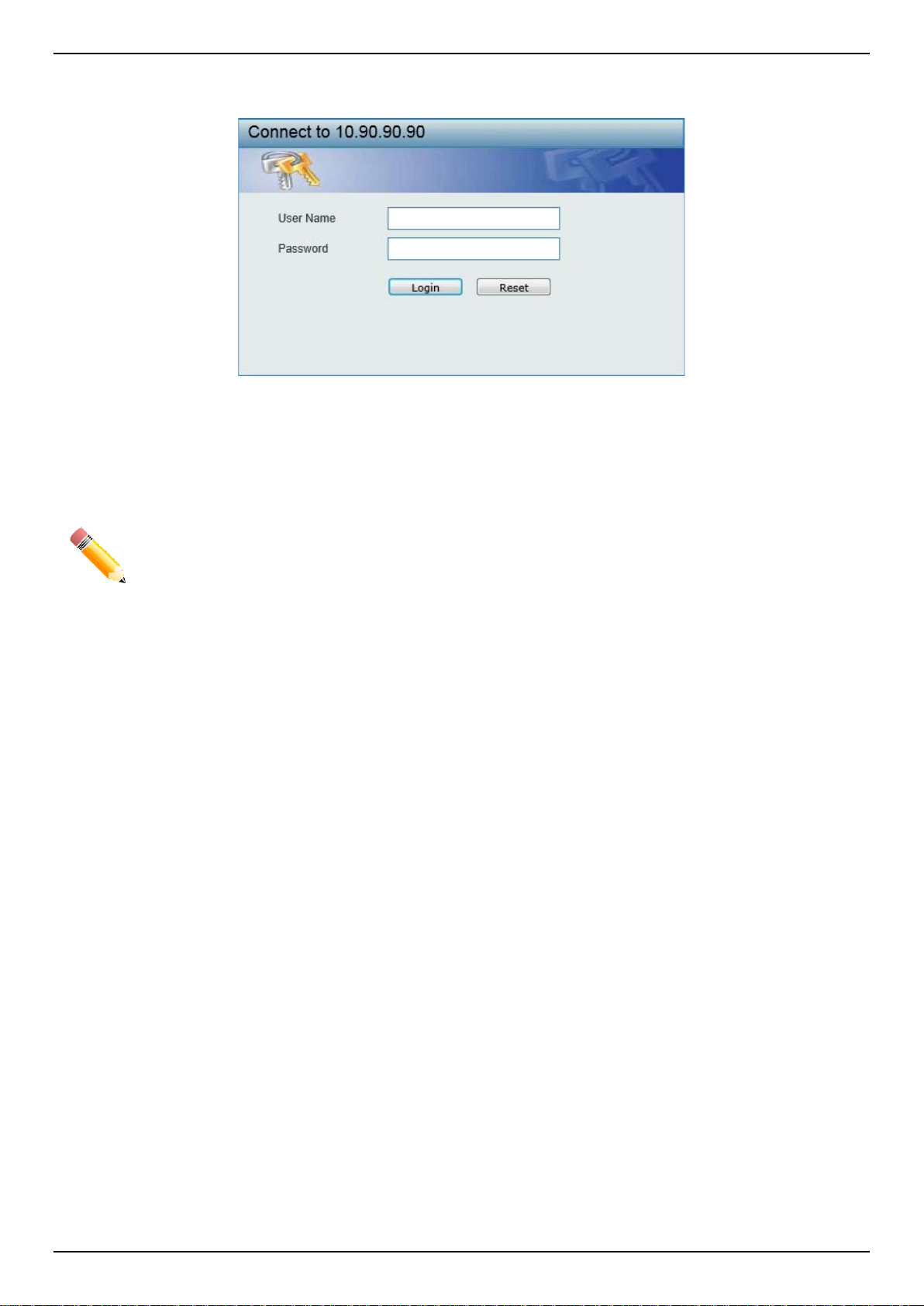
After pressing the ENTER key, the following aut hentication window should appear, as shown below.
Figure 2-2 Web UI Login Window
When connecting to the Web UI of the Switch for the first time, leave the User Name and Password fields blank and
click Login since there are no login user accounts creat ed by default on the Switch.
NOTE: After a user account was created, login credentials will be required t o access the Web UI.
During the sending and receiving of the login password to and from the Switch, this information
will be protected using a strong encryption algorithm to prevent attackers from snooping thi s
information to gain unauthorized access to t he Switch.
Web User Interface (Web UI)
The Web UI provides access to various Switch configuration and management windows. It all ows the user to view
performance statistics, and permits graphical monitoring of the system’s status.
Areas of the User Interface
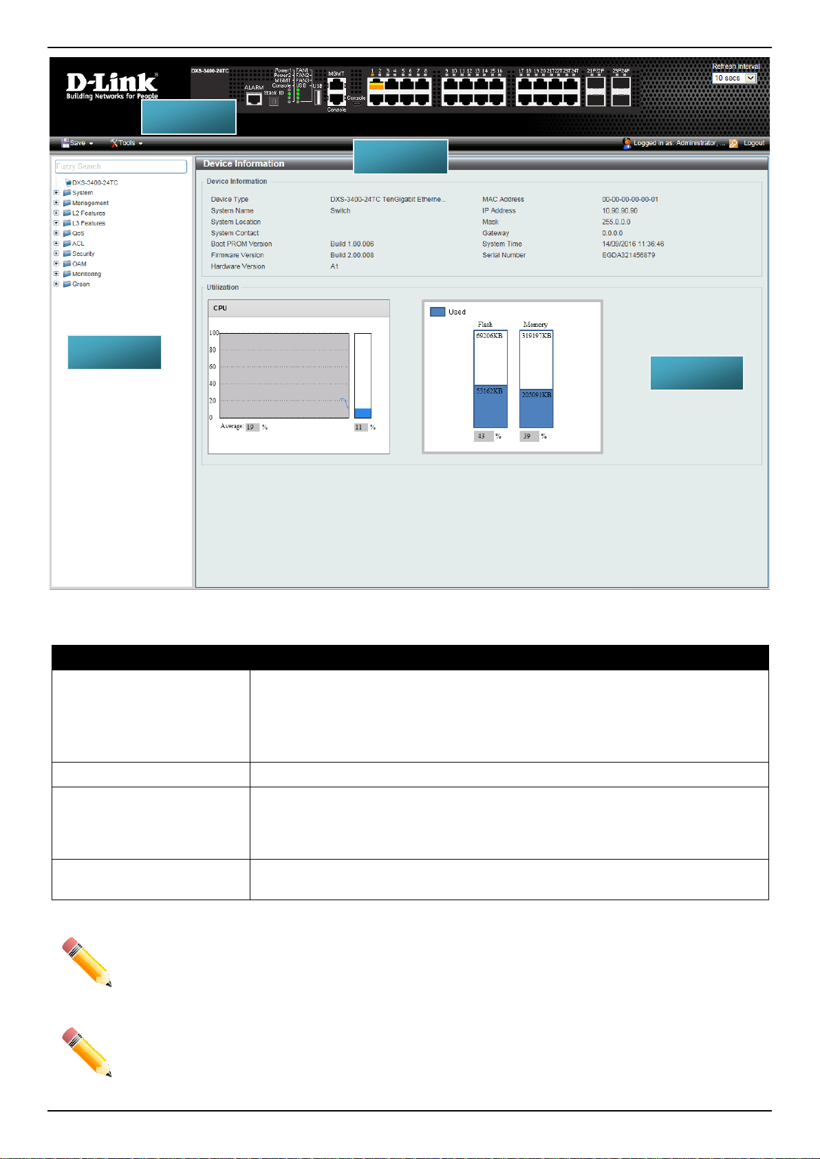
The figure below shows the user interface. Four distinct areas that divide the user interface, as described in the table.
3
Page 14
DXS-3400 Series Lite Layer 3 Stackable 10GbE Managed Switch Web UI Reference Guide
AREA 3
AREA 1
AREA 4
AREA 2
Area Number Description
AREA 1
This area displays a graphical, near real-time im age of the front panel of the
Switch. This area displays the Switch’s ports and ex pansion modules. It also
shows port activity based on a specific mode. S om e management functions,
including port monitoring, are accessible from here.
Click the D-Link logo to go to the D-Link website.
AREA 2
AREA 3
This area displays a toolbar used to access Save and Tools menus.
This area displays a file explorer-type menu tree with all configurable options.
Select the folder or window to display. Open folders and click the hyperlinked
window buttons and subfolders contained withi n them to display information
pertaining to that category.
AREA 4
In this area, the Switch’s configuration page c an be found, based on the selection
made in AREA 3.
NOTE: The Switch only supports ASCII characters for input values.
Figure 2-3 Main Web UI Window
NOTE: The best screen resolution for viewing the Web UI is 1280 x 1024 pixel s.
4
Page 15
DXS-3400 Series Lite Layer 3 Stackable 10GbE Managed Switch Web UI Reference Guide
3. System
Device Information
System Information Settings
Peripheral Settings
Port Configuration
Loopback Test
System Log
Time and SNTP
Time Range
PTP (Precise Time Protocol)
USB Console Settings
SRM
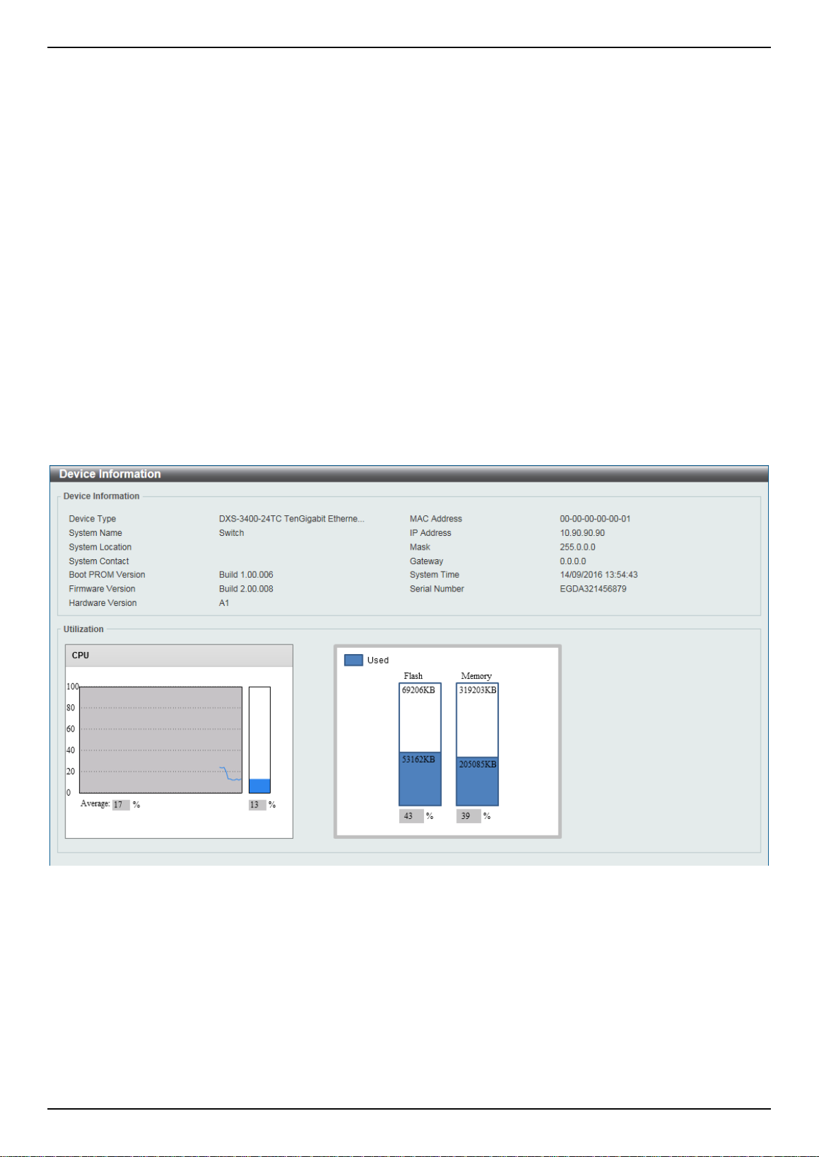
Device Information
In the Device Information section, the us er can view a list of basic information regarding the Switch. It appears
automatically when you log on to the Switch. To return to the Device Information window after viewing other windows,
click the DXS-3400-24TC link.
Figure 3-1 Device Information Win dow
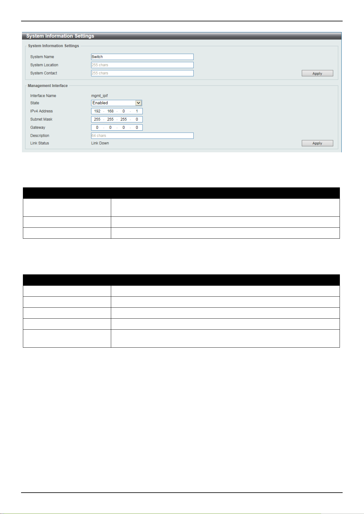
System Information Settings
This window is used to display and configure the system information settings and manageme nt interface configuration
settings.
To view the following window, click System > System Information Settings, as shown below:
5
Page 16
DXS-3400 Series Lite Layer 3 Stackable 10GbE Managed Switch Web UI Reference Guide
.
Figure 3-2 System Information Settings Window
The fields that can be configured in System Information Settings are described below:
Parameter Description
System Name
System Location
System Contact
Click the Apply button to accept the changes made.
The fields that can be configured in Management I nterface are described below:
Parameter Description
State
IPv4 Address
Subnet Mask
Gateway
Description
Click the Apply button to accept the changes made.
Enter a system name for the Switch, if so desired. This name will identify it in the
Switch network.
Enter the location of the Switch, if so desired.
Enter a contact name for the Switch, if so desired.
Select to enable or disable this interface here.
Enter the IPv4 address for this interface here.
Enter the IPv4 subnet mask for this interf ace here.
Enter the gateway IPv4 address for this interface here .
Enter the description for the management interface here. This can be up to 64
characters long.
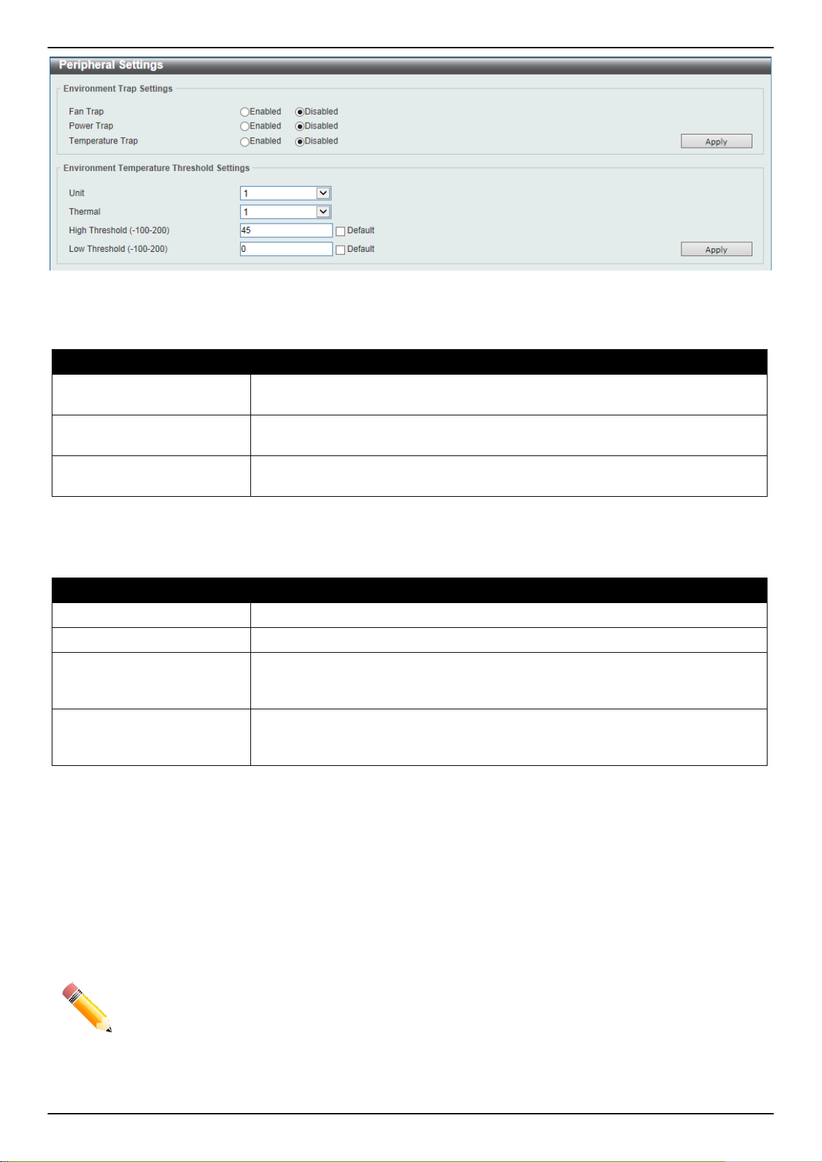
Peripheral Settings
This window is used to display and configure the environment trap settings and environment temperature threshold
settings.
To view the following window, click System > Peripheral Settings, as shown below:
6
Page 17
DXS-3400 Series Lite Layer 3 Stackable 10GbE Managed Switch Web UI Reference Guide
Figure 3-3 Peripheral Settings Window
The fields that can be configured in Environment Trap Settings a re described below:
Parameter Description
Fan Trap
Power Trap
Temperature Trap
Click the Apply button to accept the changes made.
The fields that can be configured in Environment Temperature Threshold Settings are described below:
Parameter Description
Unit
Thermal
High Threshold
Low Threshold
Click the Apply button to accept the changes made.
Click to enable or disable the fan trap state for warning fan event (fan failed or fan
recover).
Click to enable or disable the power trap state for warning power event (power
failed or power recover).
Click to enable or disable the temperature trap state for warning temperature
event (temperature exceeds the thresholds or temperature recover).
Select the Switch unit that will be used for this configuration here.
Select the thermal sensor ID.
Enter the high threshold value of the warning t em perature setting. The range is
from -100 to 200 Celsius degree. Tick the Default check box to return to the
default value.
Enter the low threshold value of the warning tempe rature setting. The range is
from -100 to 200 Celsius degree. Tick the Default check box to return to the
default value.
Port Configuration
Port Settings
This window is used to display and configure the Switch’s port settings.
NOTE: The 10M and 100M speed options are only applicable when connecting to the Management
Port (Mgmt 0) is used.
To view the following window, click System > Port Configuration > Port Settings, as shown below:
7
Page 18
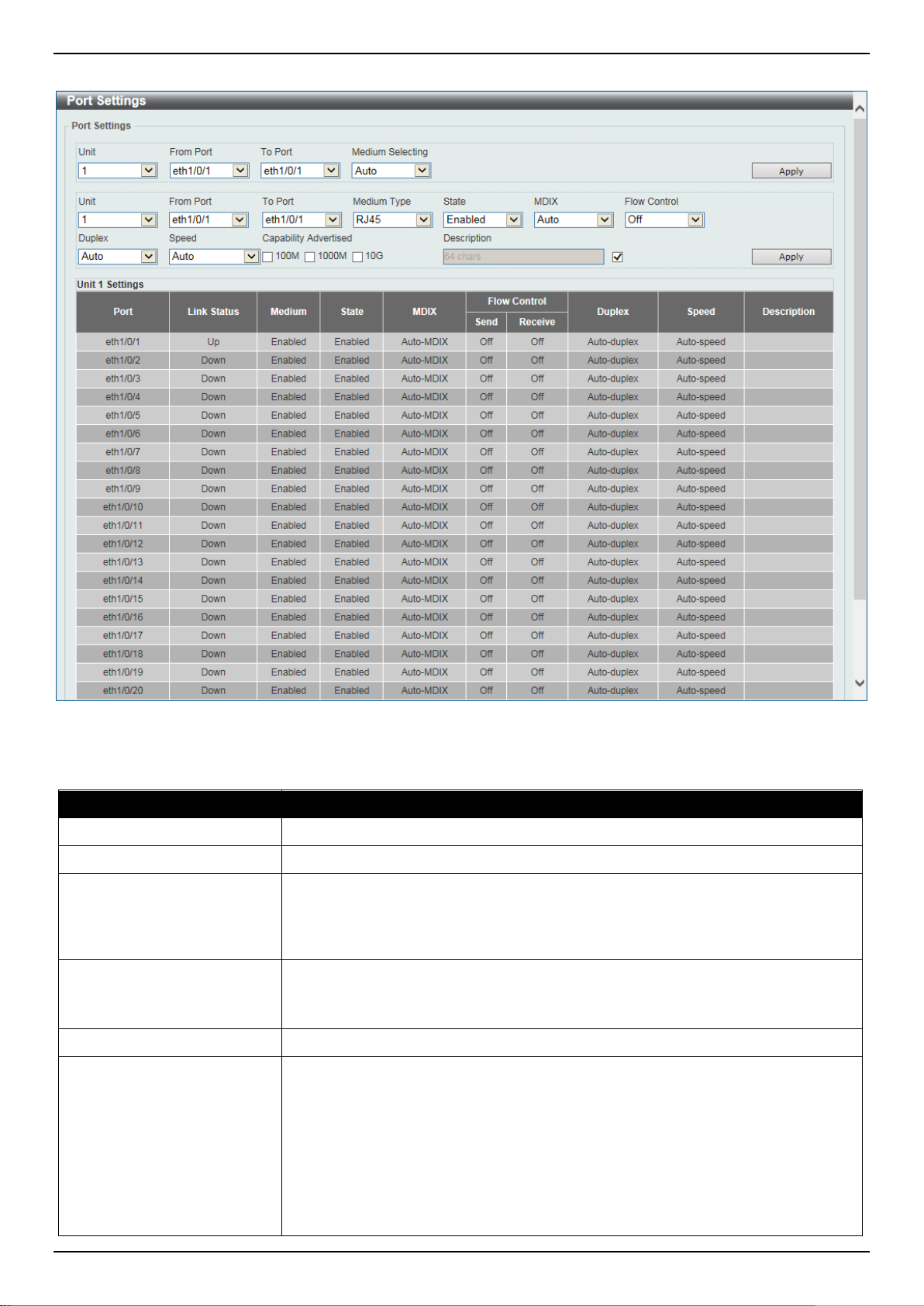
DXS-3400 Series Lite Layer 3 Stackable 10GbE Managed Switch Web UI Reference Guide
• Cross - Select this option for cross cabling. I f this option is selected, the port
Figure 3-4 Port Settings Window
The fields that can be configured are described below:
Parameter Description
Unit
From Port ~ To Port
Medium Selecting
Select the stacking unit ID of the Switch that will be configured he re.
Select the appropriate port range used for the configuration here.
Select the port medium type here. Options to ch oose from are Auto, RJ45 and
SFP.
Note: Selecting the SFP option, includes the use of SFP+ tran sceivers for 10G
connectivity.
Medium Type
Select the port medium type here. Options to ch oose from are RJ45 and SFP.
Note: Selecting the SFP option, includes the use of SFP+ tran sceivers for 10G
connectivity.
State
MDIX
Select this option to enable or disabled the physical port here.
Select the Medium Dependent Interface Cros sov er (MDIX) option here. Options to
choose from are Auto, Normal, and Cross.
• Auto - Select this option for auto-sensing of the optimal type of cabling.
• Normal - Select this option for normal cabling. If this option is selected, the
port is in the MDIX mode and can be connected to a PC’s NIC using a
straight-through cable or a port (in the MDI mode) on another switch through
a cross-over cable.
8
Page 19

DXS-3400 Series Lite Layer 3 Stackable 10GbE Managed Switch Web UI Reference Guide
is in the MDI mode and can be connected to a port (in the MDIX mode) on
Parameter Description
another switch through a straight cable.
Flow Control
Duplex
Speed
Select to either turn flow control On or Off here. Port s configured for full-duplex
use 802.3x flow control, half-duplex ports use bac k-pressure flow control, and
Auto ports use an automatic selection of the two.
Select the duplex mode used here. Options to choo se from are Auto and Full.
Select the port speed option here. This option will manually force the connection
speed on the selected port to only connect at the speed specified here.
Options to choose from are Auto, 100M, 1000M, 1000M Master, 1000M S lave,
10G, 10G Master, and 10G Slave.
The Master setting will allow the port to advert i se capabilities related to duplex,
speed and physical layer type. The master setting will also determine the master
and slave relationship between the two connected physical layers. This
relationship is necessary for establishing the timing control between the two
physical layers. The timing control is set on a mast er physical layer by a local
source.
The Slave setting uses loop timing, where the timing comes from a data st ream
received from the master. If one connection i s s et for master, the other side of the
connection must be set for slave. Any other configuration will result in a link down
status for both ports.
• Auto - Specifies that for copper ports, auto-negotiation wil l st art to negotiate
the speed and flow control with its link partner. F or fiber ports, autonegotiation will start to negotiate the clock a nd flow control with its link
partner.
• 100M - Specifies to force the port speed t o 100M bps. This option is only
available for 100Mbps copper connections.
• 1000M - Specifies to force the port speed to 1Gbps. This option is only
available for 1Gbps fiber connections.
• 1000M Master - Specifies to force the port speed to 1Gbps and operates as
the master, to facilitate the timing of transmit and receive operations. This
option is only available for 1Gbps copper connections.
• 1000M Slave - Specifies to force the port speed t o 1Gbps and operates as
the slave, to facilitate the timing of transm it and receive operations. This
option is only available for 1Gbps copper connections.
• 10G - Specifies to force the port speed to 10Gbps. This option is only
available for 10Gbps fiber connections.
• 10G Master - Specifies to force the port speed to 10Gbps and operates as
the master, to facilitate the timing of transmit and receive operations. This
option is only available for 10Gbps copper connections.
• 10G Slave - Specifies to force the port speed to 10Gbps and operates as the
slave, to facilitate the timing of transmit and receive operations. This option is
only available for 10Gbps copper connect ions.
Capability Advertised
When the Speed is set to Auto, these capabilities are advertised during autonegotiation.
Description
Enter a 64 characters description for the corresponding port here.
Click the Apply button to accept the changes made.
NOTE: When the state of a port is disabled, settings associated with the port can still be configured.
However, the modified settings will only take effect when the state of the port is enabled.
9
Page 20
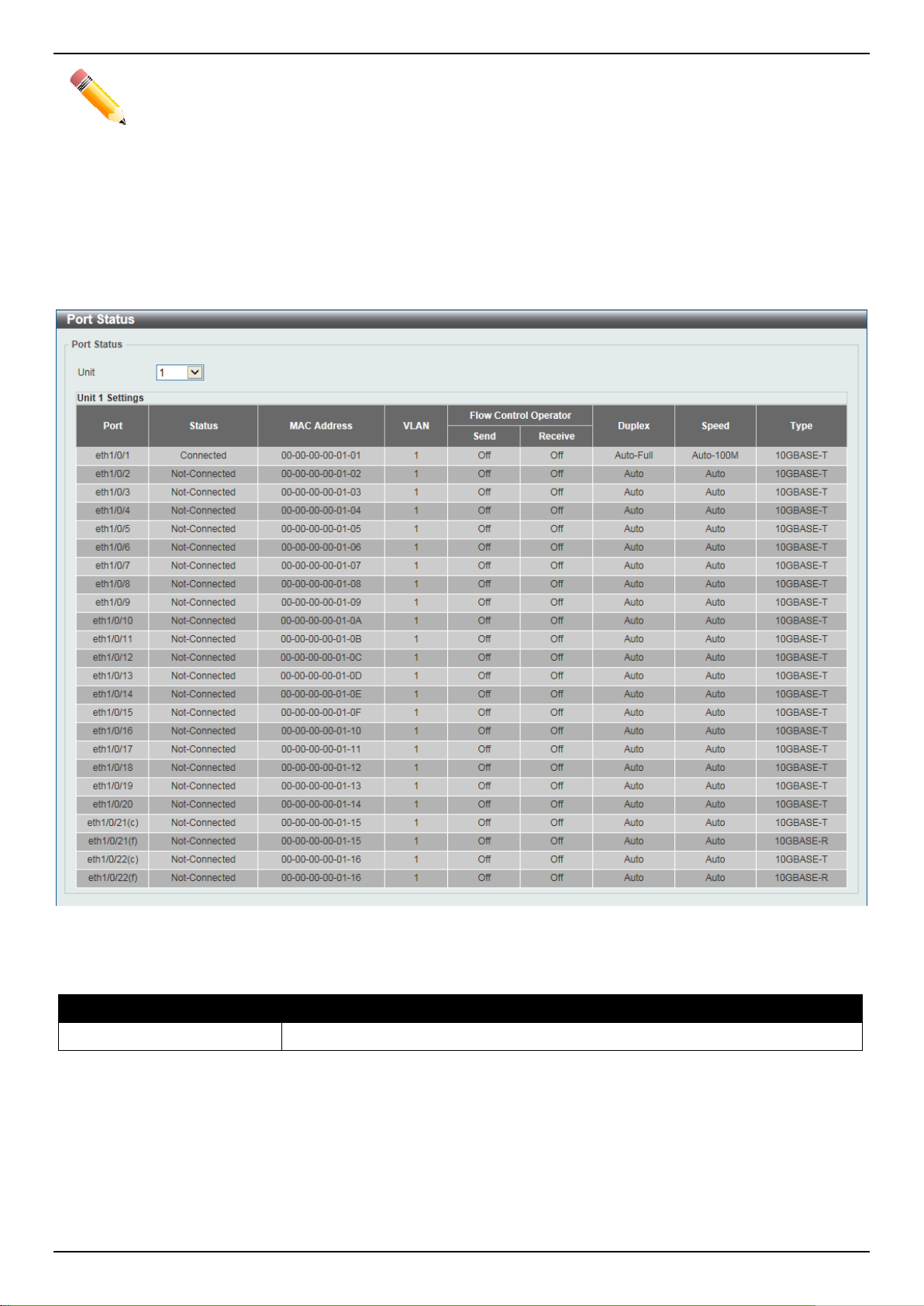
DXS-3400 Series Lite Layer 3 Stackable 10GbE Managed Switch Web UI Reference Guide
NOTE: When the state of a combo port is enabled/disabled, regardless of the Medium Type selected,
both the RJ45 and SFP ports will be enabled/disabled.
Port Status
This window is used to display the Switch’s physical port status and settings.
To view the following window, click System > Port Configuration > Port Status, as shown below:
Figure 3-5 Port Status Window
The fields that can be configured are described below:
Parameter Description
Unit
Select the stacking unit ID of the Switch that will be displayed her e.
Port GBIC
This window is used to display active GBIC information found on each applicable physical port of the Switch.
To view the following window, click System > Port Configuration > Port GBIC, as shown below:
10
Page 21

DXS-3400 Series Lite Layer 3 Stackable 10GbE Managed Switch Web UI Reference Guide
Figure 3-6 Port GBIC Window
The fields that can be configured are described below:
Parameter Description
Unit
Select the Switch unit that will be used for this display here.
Port Auto Negotiation
This window is used to display detailed port auto-negotiation information.
To view the following window, click System > Port Configuration > Port Auto Negotiation, as shown below:
11
Page 22
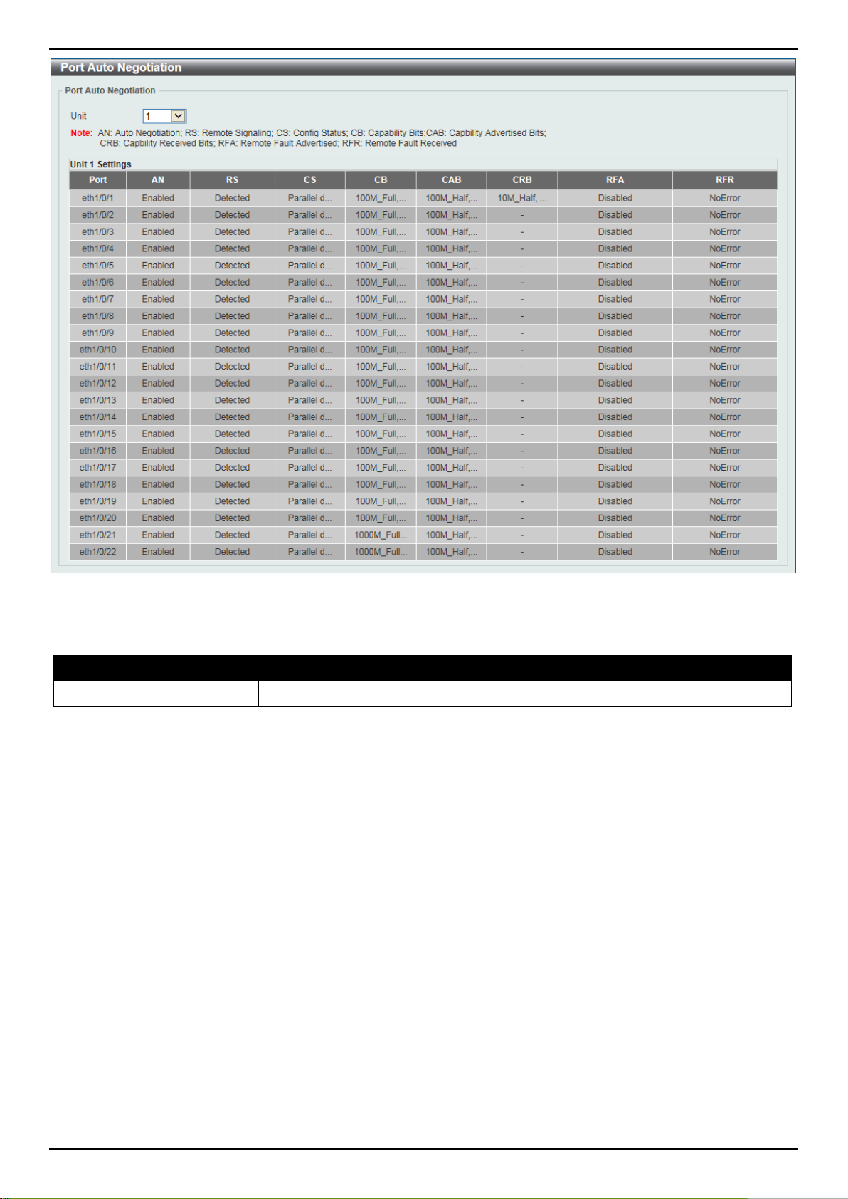
DXS-3400 Series Lite Layer 3 Stackable 10GbE Managed Switch Web UI Reference Guide
Figure 3-7 Port Auto Negotiation Window
The fields that can be configured are described below:
Parameter Description
Unit
Select the stacking unit ID of the Switch that will be displayed her e.
Error Disable Settings
This window is used to display and configure the e rror recovery for causes and to configure the recovery interval.
To view the following window, click System > Port Configuration > Error Disable Settings, as shown below:
12
Page 23
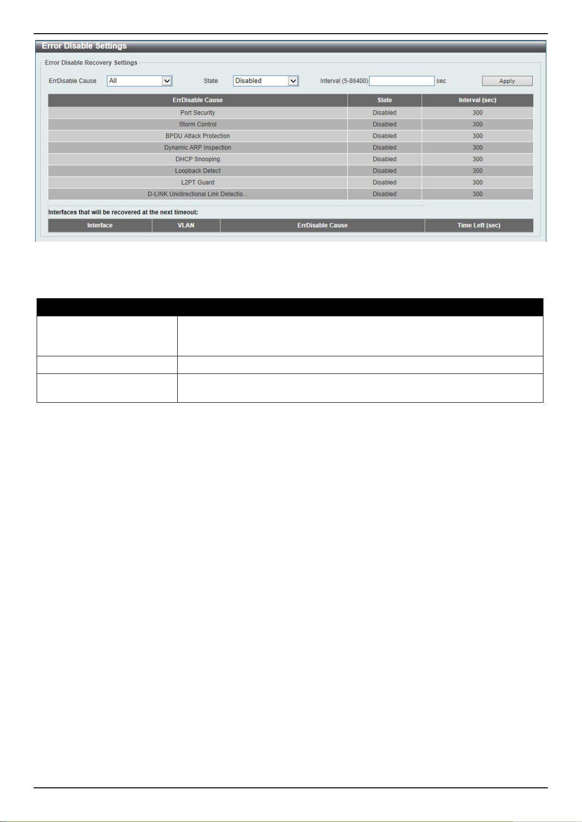
DXS-3400 Series Lite Layer 3 Stackable 10GbE Managed Switch Web UI Reference Guide
Figure 3-8 Error Disable Settings Window
The fields that can be configured are described below:
Parameter Description
ErrDisable Cause
State
Interval
Click the Apply button to accept the changes made.
Select the error disabled cause here. Options to choose from are Port Security,
Storm Control, BPDU Attack Protection, Dynamic ARP Inspection, DHCP
Snooping, and Loopback Detect.
Select the enable or disable the error disabled re covery feature here.
Enter the time, in seconds, to recover the port from th e error state caused by the
specified module. The range is from 5 to 86400.
Jumbo Frame
This window is used to display and configure the Jumbo Frame size and settings. The Switch supports jumbo frames.
Jumbo frames are Ethernet frames with more tha n 1,518 bytes of payload. The Switch supports jumbo frames with a
maximum frame size of up to 12288 bytes.
To view the following window, click System > Port Configuration > Jumbo Frame, as shown below:
13
Page 24
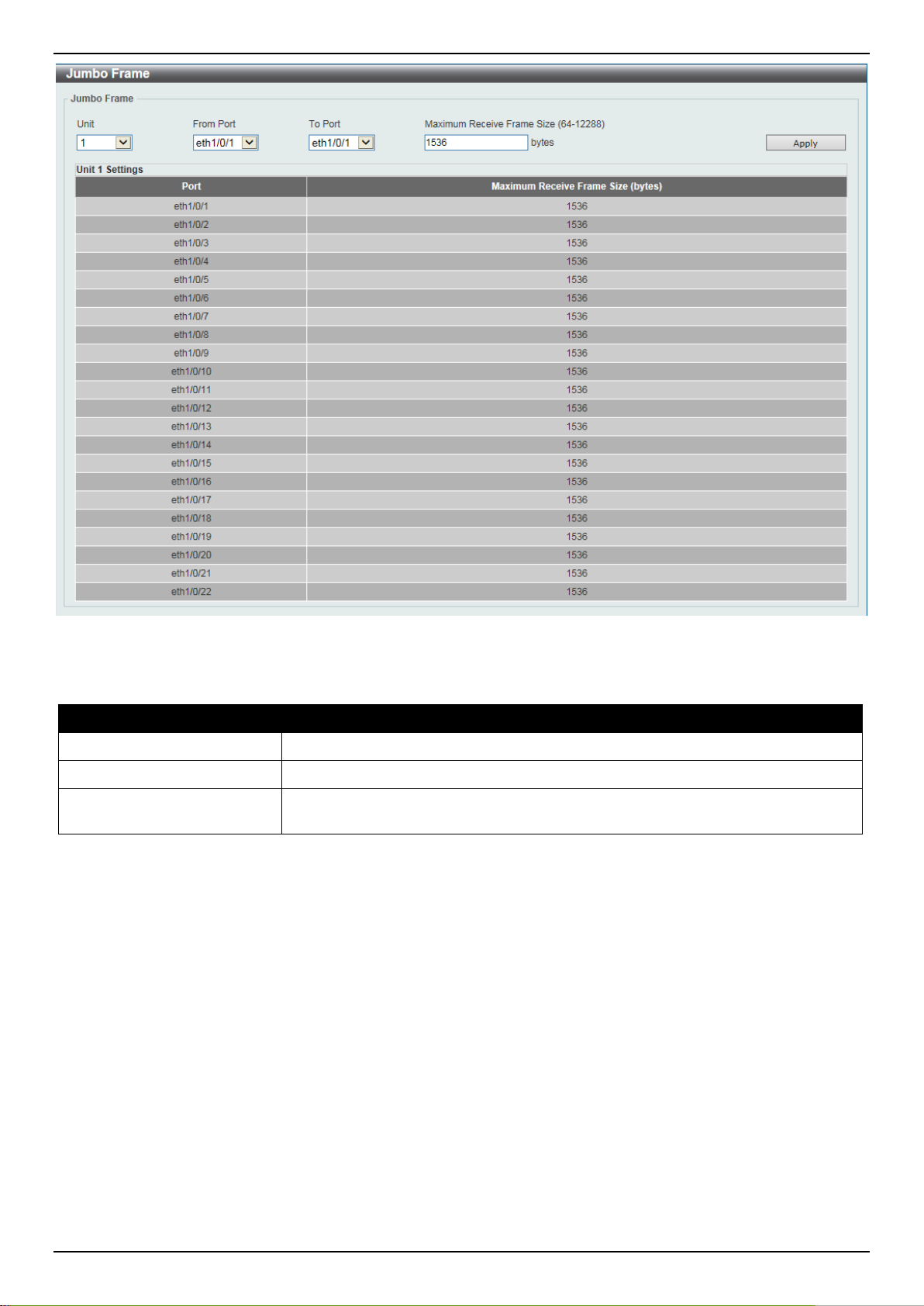
DXS-3400 Series Lite Layer 3 Stackable 10GbE Managed Switch Web UI Reference Guide
Figure 3-9 Jumbo Frame Window
The fields that can be configured are described below:
Parameter Description
Unit
From Port ~ To Port
Maximum Receive Frame
Size
Click the Apply button to accept the changes made.
Select the stacking unit ID of the Switch that will be configured here.
Select the appropriate port range used for the configuration here.
Enter the maximum receive frame size value her e. This value must be between
64 and 12288 bytes. By default, this value is 1536 bytes.
Loopback Test
This window is used to display and configure the loopback settings of the physical port interfaces and to start testing.
To view the following window, click System > Loopback Test, as shown below:
14
Page 25
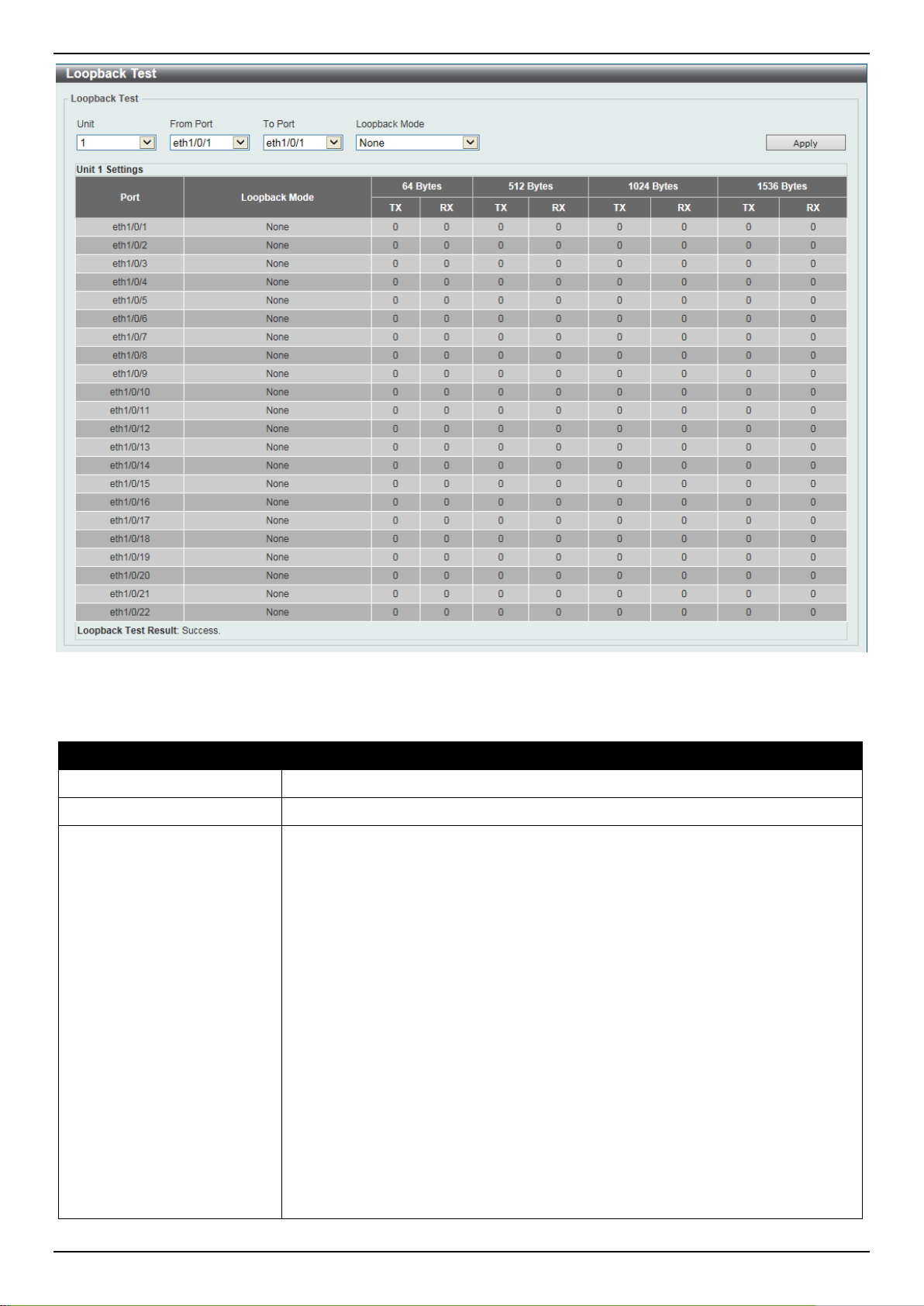
DXS-3400 Series Lite Layer 3 Stackable 10GbE Managed Switch Web UI Reference Guide
Figure 3-10 Loopback Test Window
The fields that can be configured are described below:
Parameter Description
Unit
From Port ~ To Port
Loopback Mode
Select the Switch unit that will be used for this configuration here.
Select the appropriate port range used for the configuration here.
Select the loopback mode here. Options to choo se f rom are:
• None - Specifies not to enable the loopback mode.
• Internal MAC - Specifies the internal loopback mode at the MAC layer.
• Internal PHY Default - Specifies the internal loopback mode at the PHY
layer to test the default medium.
• Internal PHY Copper - Specifies the internal loopback mode at the PHY
layer to test the copper medium.
• Internal PHY Fiber - Specifies the internal loopback mode at the PHY layer
to test the fiber medium.
• External MAC - Specifies the external loopb ack mode at the MAC layer.
• External PHY Default - Specifies the external loopback mode at the PHY
layer to test the default medium.
• External PHY Copper - Specifies the external loopback mode at the PHY
layer to test the copper medium.
• External PHY Fiber - Specifies the external loopback mode at the PHY layer
to test the fiber medium.
15
Page 26
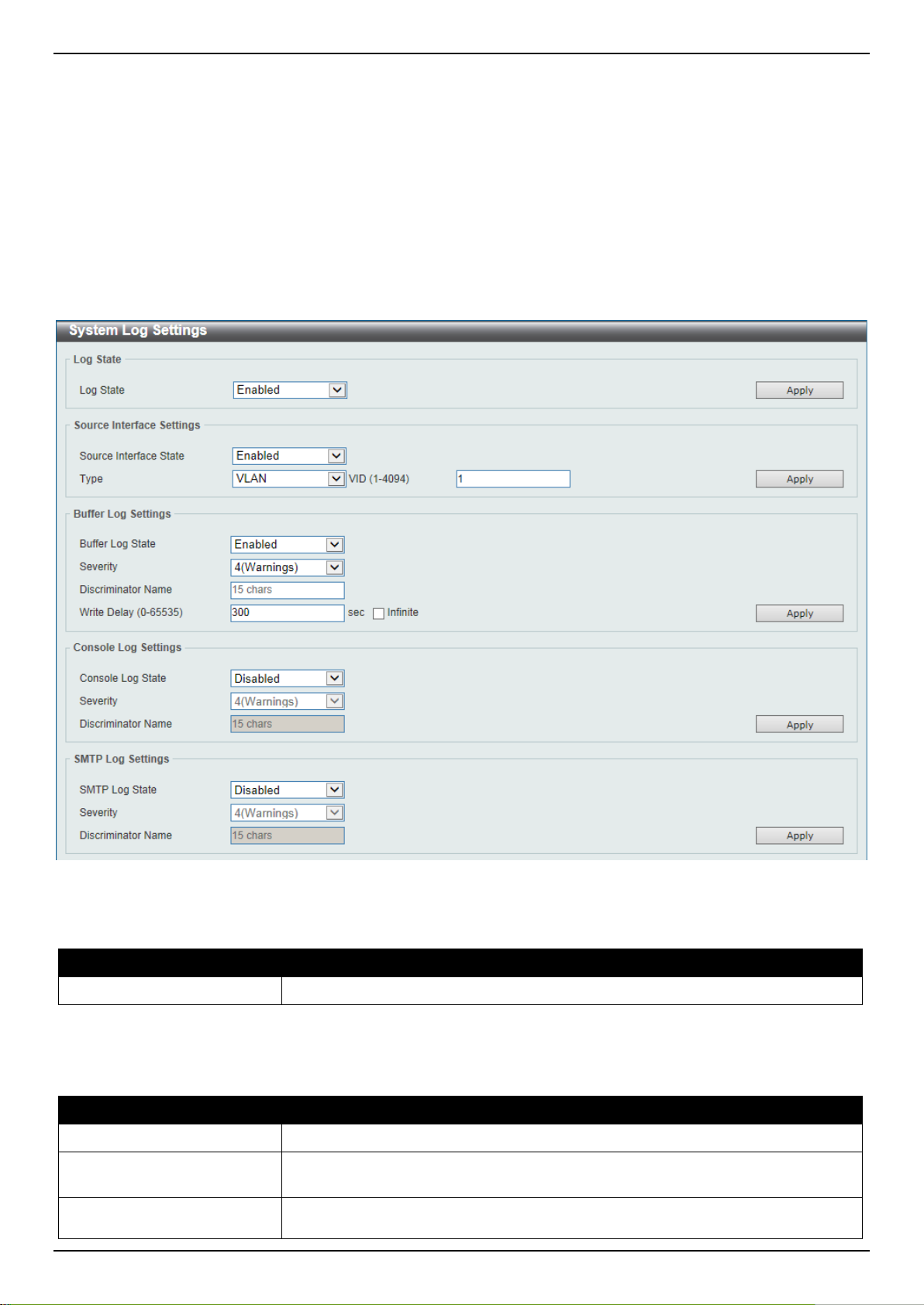
DXS-3400 Series Lite Layer 3 Stackable 10GbE Managed Switch Web UI Reference Guide
to 8. For the management (Mgmt) interface this val ue is always 0. For VLAN
Click the Apply button to accept the changes made.
System Log
System Log Settings
This window is used to display and configure the sy st em’s log setti ngs.
To view the following window, click System > System Log > System Log Settings, as shown below:
Figure 3-11 System Log Settings Window
The fields that can be configured for Log State are described below:
Parameter Description
Log State
Click the Apply button to accept the changes made.
The fields that can be configured for Source Interface Settings are described below:
Parameter Description
Source Interface State
Type
VID
Select the enable or disable the system log feature’s global state here.
Select this option to enable or disable the source i nterface’s global state.
Select the type of interface that will be used. Options to cho ose from are
Loopback, Mgmt, and VLAN.
Enter the interface’s VID used here. For loopba ck interfaces this ID can be from 1
16
Page 27

DXS-3400 Series Lite Layer 3 Stackable 10GbE Managed Switch Web UI Reference Guide
interfaces this value is from 1 to 4094.
Parameter Description
Click the Apply button to accept the changes made.
The fields that can be configured for Buffer Log Settings are described below:
Parameter Description
Buffer Log State
Severity
Discriminator Name
Write Delay
Click the Apply button to accept the changes made.
The fields that can be configured for Console Log Settings are described below:
Parameter Description
Console Log State
Severity
Discriminator Name
Select whether the enable or disable the buff er l og’ s global state here. Options to
choose from are Enable, Disabled, and Default. When selecting the Default
option, the buffer log’s global state will fol l ow the default behavior.
Select the severity value of the type of informati on that will be logged. Options to
choose from are 0 (Emergencies), 1 (Alerts), 2 (Critical), 3 (Errors), 4
(Warnings), 5 (Notifications), 6 (Inform ational ), and 7 (Debugging).
Enter the discriminator name used here. This nam e can be up to 15 characters
long.
Enter the log’s write delay value here. This value must be between 0 and 65535
seconds. By default, this value is 300 second s. T ick the Infinite option, to disable
the write delay feature.
Select whether the enable or disable the console log’s global state here.
Select the severity value of the type of information that will be logged. Options to
choose from are 0 (Emergencies), 1 (Alerts), 2 (Critical), 3 (Errors), 4
(Warnings), 5 (Notifications), 6 (Inform ational ), and 7 (Debugging).
Enter the discriminator name used here. This nam e can be up to 15 characters
long.
Click the Apply button to accept the changes made.
The fields that can be configured for SMTP Log Settings are described below:
Parameter Description
SMTP Log State
Severity
Discriminator Name
Click the Apply button to accept the changes made.
Select whether the enable or disable the SMTP log’ s global state here.
Select the severity value of the type of informati on that will be logged. Options to
choose from are 0 (Emergencies), 1 (Alerts), 2 (Critical), 3 (Errors), 4
(Warnings), 5 (Notifications), 6 (Inform ational ), and 7 (Debugging).
Enter the discriminator name used here. This nam e can be up to 15 characters
long.
System Log Discriminator Settings
This window is used to display and configure the system log’s discriminator settings.
To view the following window, click System > System Log > System Log Discriminator Settings, as shown below:
17
Page 28
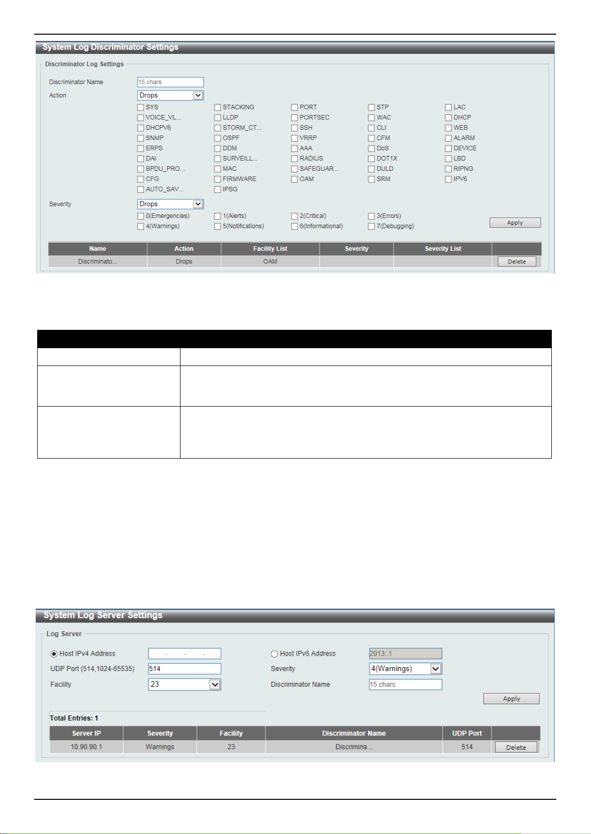
DXS-3400 Series Lite Layer 3 Stackable 10GbE Managed Switch Web UI Reference Guide
Figure 3-12 System Log Discriminator Settings Window
The fields that can be configured are described bel ow:
Parameter Description
Discriminator Name
Action
Severity
Click the Apply button to accept the changes made.
Click the Delete button to delete the specified entry.
Enter the discriminator name here. This name ca n be up to 15 characters long.
Select the facility’s behavior option and the type of facility that will be associated
with the selected behavior here. Behavior options to choos e from are Drops and
Includes.
Select the severity behavior option and the value of the type of information that
will be logged. Behavior options to choose from a re Drops and Includes. Severity
value options to choose from are 0 (Emergencies), 1 (Alerts), 2 (Critical), 3
(Errors), 4 (Warnings), 5 (Notifications), 6 (Informational), and 7 (Debugging).
System Log Server Settings
This window is used to display and configure sy stem l og’s serve r setti ngs.
To view the following window, click System > System Log > System Log Server Settings, as shown below:
Figure 3-13 System Log Server Settings Window
18
Page 29
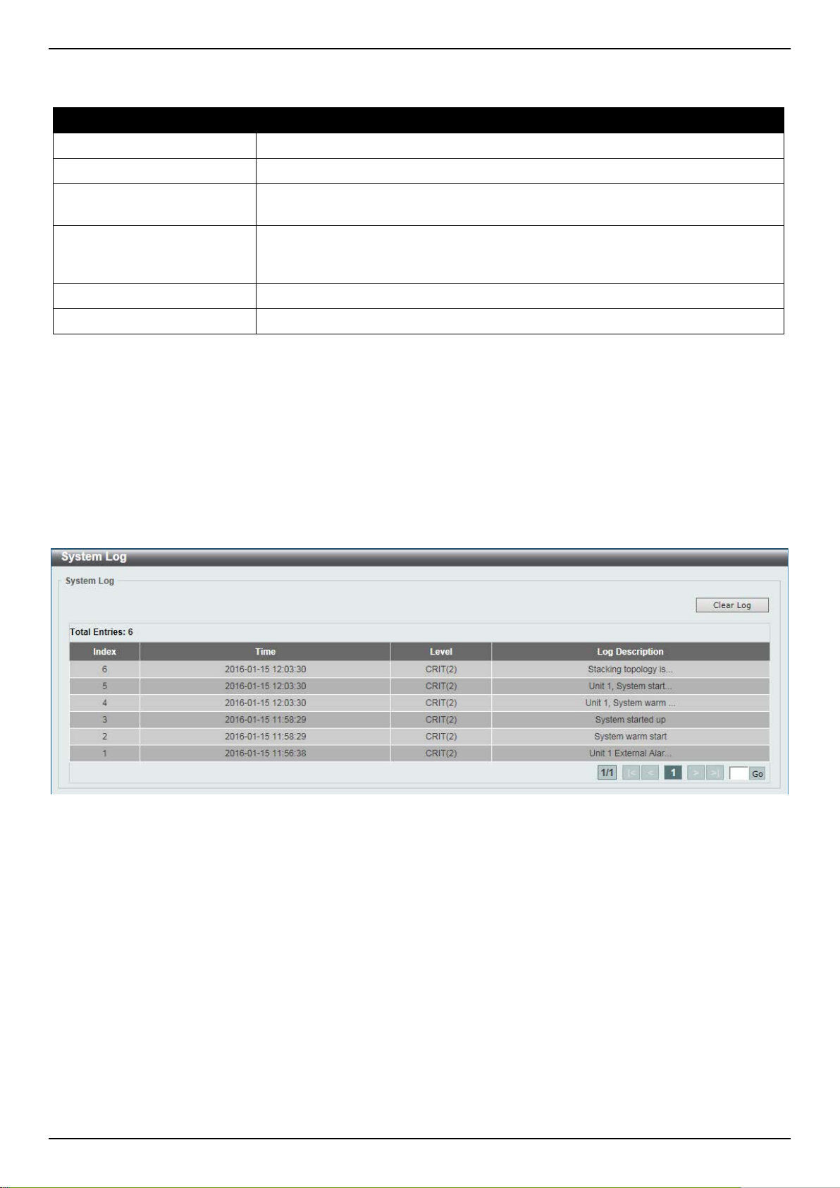
DXS-3400 Series Lite Layer 3 Stackable 10GbE Managed Switch Web UI Reference Guide
The fields that can be configured are described below:
Parameter Description
Host IPv4 Address
Host IPv6 Address
UDP Port
Severity
Facility
Discriminator Name
Click the Apply button to accept the changes made.
Click the Delete button to delete the specified entry.
Enter the system log server’s IPv4 address here.
Enter the system log server’s IPv6 address here.
Enter the system log server’s UDP port number here. This value must be either
514 or between 1024 and 65535. By default, t his value is 514.
Select the severity value of the type of informati on that will be logged. Options to
choose from are 0 (Emergencies), 1 (Alerts), 2 (Critical), 3 (Errors), 4
(Warnings), 5 (Notifications), 6 (Inform ational ), and 7 (Debugging).
Select the facility value here. Options to choo se from are 0 to 23.
Enter the discriminator name here. This name ca n be up to 15 characters long.
System Log
This window is used to display and clear the system log.
To view the following window, click System > System Log > System Log, as shown below:
Figure 3-14 System Log Window
Click the Clear Log button to clear the system log entries displ ayed in the table.
Enter a page number and click the Go button to navigate to a specific page when multiple pages exist.
System Attack Log
This window is used to display and clear the system attack log.
To view the following window, click System > System Log > System Attack Log, as shown below:
19
Page 30
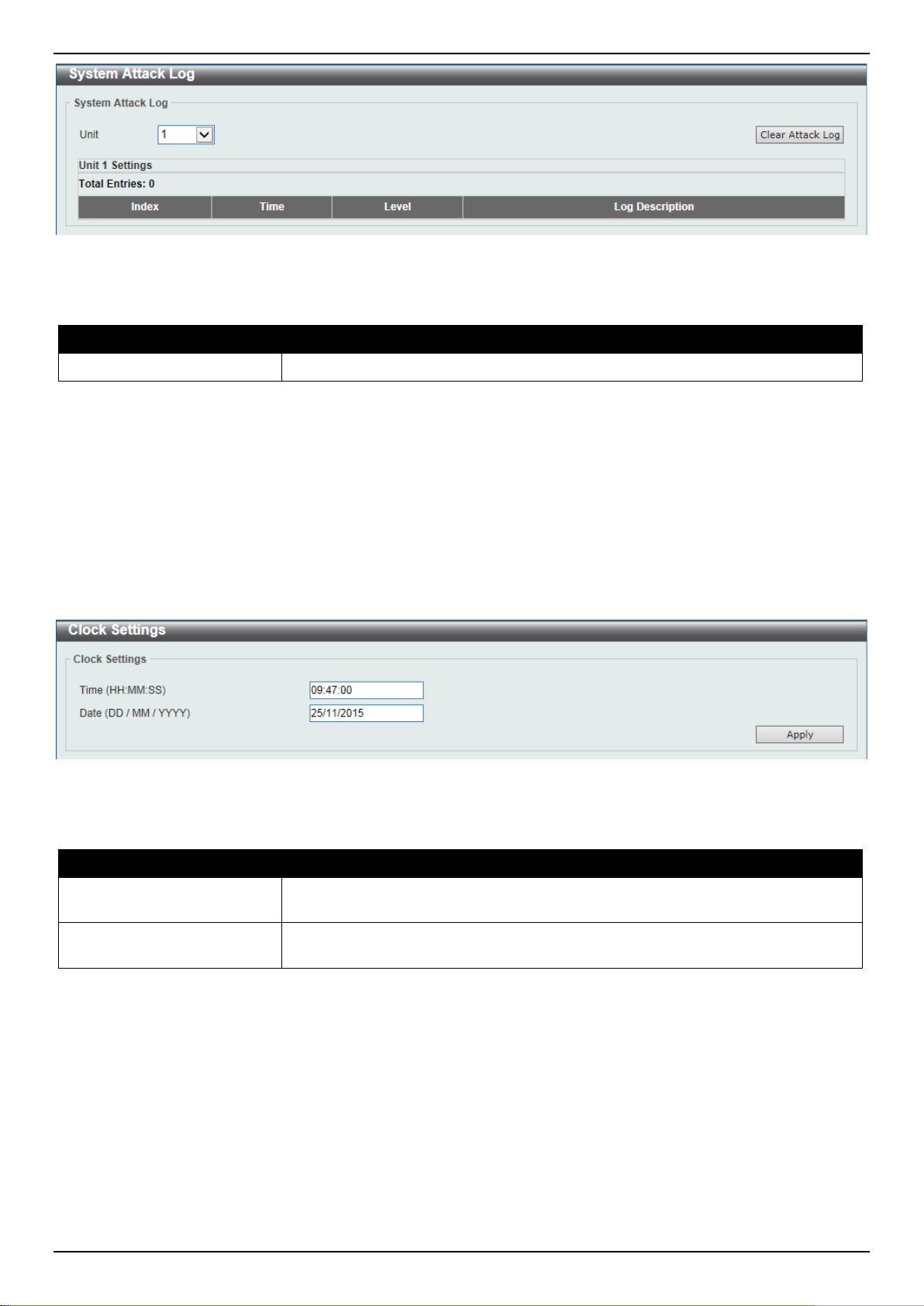
DXS-3400 Series Lite Layer 3 Stackable 10GbE Managed Switch Web UI Reference Guide
Figure 3-15 System Attack Log Window
The fields that can be configured are described below:
Parameter Description
Unit
Click the Clear Attack Log button to clear the system attack log entries displayed in the table.
Select the stacking unit ID of the Switch that will be displayed her e.
Time and SNTP
Clock Settings
This window is used to display and configure the time settings for the Switch.
To view the following window, click System > Time and SNTP > Clock Settings, as shown below:
Figure 3-16 Clock Settings Window
The fields that can be configured are described below:
Parameter Description
Time
Date
Click the Apply button to accept the changes made.
Enter the current time in hours (HH), minutes (MM), and seconds (SS) here. For
example, 18:30:30.
Enter the current day (DD), month (MM), and year (YY) here. For ex am ple,
30/04/2015.
Time Zone Settings
This window is used to display and configure tim e zones and Daylight Savings Time settings for S NTP .
To view the following window, click System > Time and SNTP > Time Zone Settings, as shown below:
20
Page 31

DXS-3400 Series Lite Layer 3 Stackable 10GbE Managed Switch Web UI Reference Guide
Figure 3-17 Time Zone Settings Window
The fields that can be configured are described below:
Parameter Description
Summer Time State
Select the summer time setting. Options t o choose from are Disabled, Recurring
Setting, and Date Setting.
• Disabled - Select to disable the summer ti m e set ting.
• Recurring Setting - Select to configure the summer tim e that should start
and end on the specified week day of the specified month.
• Date Setting - Select to configure the summer ti m e that should start and end
on the specified date of the specified month.
Time Zone
Select to specify your local time zone’s offset f rom Coordinated Universal Time
(UTC).
The fields that can be configured in Recurring Settings are d escribed below:
Parameter Description
From: Week of the Month
Select week of the month that summer time will start.
From: Day of the Week
From: Month
From: Time
Select the day of the week that summer time will st art.
Select the month that summer time will start.
Select the time of the day that summer time will st art.
21
Page 32

DXS-3400 Series Lite Layer 3 Stackable 10GbE Managed Switch Web UI Reference Guide
Parameter Description
To: Week of the Month
To: Day of the Week
To: Month
To: Time
Offset
The fields that can be configured in Date Settin g s are described below:
Parameter Description
From: Date of the Month
From: Month
From: Year
From: Time
To: Date of the Month
To: Month
To: Year
To: Time
Select week of the month that summer time will end.
Select the day of the week that summer time will end.
Select the month that summer time will end.
Select the time of the day that summer time will end.
Enter the number of minutes to add during summer time. The default value is 60.
The range of this offset is 30, 60, 90 and 120.
Select date of the month that summer time will start.
Select the month that summer time will start.
Enter the year that the summer time will start .
Select the time of the day that summer time will st art.
Select date of the month that summer time will end.
Select the month that summer time will end.
Enter the year that the summer time will end.
Select the time of the day that summer time will end.
Offset
Click the Apply button to accept the changes made.
Enter the number of minutes to add during summer time. The default value is 60.
The range of this offset is 30, 60, 90 and 120.
SNTP Settings
This window is used to display configure the SNTP settings for the Switch.
To view the following window, click System > Time and SNTP > SNTP Settings, as shown below:
Figure 3-18 SNTP Settings Window
The fields that can be configured in SNTP Global Settings are described below:
Parameter Description
SNTP State
Select this option to enable or disable SNTP.
22
Page 33

DXS-3400 Series Lite Layer 3 Stackable 10GbE Managed Switch Web UI Reference Guide
Parameter Description
Poll Interval
Click the Apply button to accept the changes made.
The fields that can be configured in SNTP Server Settings are described below:
Parameter Description
IPv4 Address
IPv6 Address
Click the Add button to add the SNTP server.
Click the Delete button to remove the specified entry.
Enter the synchronizing interval in seconds. The value is from 30 to 99999
seconds. The default interval is 720 seconds.
Enter the IPv4 address of the SNTP server which provides the clock
synchronization.
Enter the IPv6 address of the SNTP server whi ch provides the clock
synchronization.
Time Range
This window is used to display and configure the time profile settings.
To view the following window, click System > Time Range, as shown below:
Figure 3-19 Time Range Window
The fields that can be configured are described below:
Parameter Description
Range Name
From Week ~ To Week
From Time ~ To Time
Click the Apply button to accept the changes made.
Click the Find button to locate a specific entry based on the information enter ed.
Click the Delete Periodic button to delete the periodic entry.
Enter the time profile’s range name here. This name can be up to 32 characters
long.
Select the starting and ending days of the week t hat will be used for this time
profile. Tick the Daily option to use this time profile for every day of the week. Tick
the End Week Day option to use this time profile from the starting day of the
week until the end of the week, which is Sunday .
Select the starting and ending time of the day that will be used for this time profile.
The first drop-down menu selects the hour and the second drop-down menu
selects the minute.
23
Page 34

DXS-3400 Series Lite Layer 3 Stackable 10GbE Managed Switch Web UI Reference Guide
Click the Delete button to delete the specified entry.
PTP (Precise Time Protocol)
PTP Global Settings
This window is used to display and configure the Precise Time Protocol (PTP) feature’s global settings.
To view the following window, click System > PTP (Precise Time Protocol) > PTP Global Settings, as shown below:
Figure 3-20 PTP Global Settings Window
The fields that can be configured are described below:
Parameter Description
PTP State
PTP Mode
Click the Apply button to accept the changes made.
Select to enable or disable the PTP feature here. When the PTP function is
enabled, the Switch port will add residence time to correct the fiel d. When the
PTP function is disabled, all Switch ports will forward the PTP packets according
to the multicast filtering configuration.
Select the PTP mode here.
USB Console Settings
This window is used to display and configure the USB console settings.
To view the following window, click System > USB Console Settings, as shown below:
Figure 3-21 USB Console Settings Window
The fields that can be configured are described below:
Parameter Description
USB Console State
USB Inactivity Timeout
Click the Apply button to accept the changes made.
Select to enable or disable the USB console state here.
Enter the USB inactivity timeout value here. The range is from 1 to 240 minutes.
Select the Active option to disable the timeout feature.
24
Page 35

DXS-3400 Series Lite Layer 3 Stackable 10GbE Managed Switch Web UI Reference Guide
SRM
SRM Prefer Current Settings
This window is used to display and configure the Switch Resource Management (SRM) settings. This window is used
to specify the SRM mode to be used on the Switch for optimizing resources for various functions.
To view the following window, click System > SRM > SRM Prefer Current Settings, as shown below:
Figure 3-22 SRM Prefer Current Settings Window
The fields that can be configured are described below:
Parameter Description
SRM Prefer Mode
Click the Apply button to accept the changes made.
Select the SRM prefer mode here. Options to choose f rom are:
• LAN - Specifies that the Switch prefers the LAN s witch mode.
• IP - Specifies that the Switch prefer the IP rout e m ode.
• L2VPN - Specifies that the Switch prefer the Layer 2 V P N m ode.
SRM Prefer Mode
This window is used to display the SRM preferred mode settings. The entries in this table are f ixed values indicating
the maximum number of entries allowed per feat ure.
To view the following window, click System > SRM > SRM Prefer Mode, as shown below:
Figure 3-23 SRM Prefer Mode Window
25
Page 36

DXS-3400 Series Lite Layer 3 Stackable 10GbE Managed Switch Web UI Reference Guide
The fields that can be configured are described below:
Parameter Description
SRM Prefer Mode
Select the SRM prefer mode that will be used in the display here. Options to
choose from are LAN, IP, and L2VPN.
Click the Find button to generate the display based on the selections made.
26
Page 37

DXS-3400 Series Lite Layer 3 Stackable 10GbE Managed Switch Web UI Reference Guide
4. Management
Command Logging
User Account Settings
Password Encryption
Password Recovery
Login Method
SNMP
RMON
Telnet/Web
Session Timeout
DHCP
DHCP Auto Configuration
DNS
NTP
IP Source Interface
File System
Stacking
Virtual Stacking (SIM)
D-Link Discovery Protocol
SMTP Settings
NLB FDB Settings
Command Logging
This window is used to display and configure enable or disable the command logging function. The command logging
function is used to log the commands that have su cc essfully been configured to the Switch via the command line
interface. The requirement is to log the command itself, along with information about the use r account that entered the
command into the system log. Commands that do not cause a change in the Switch configuration or operation (such
as show) will not be logged.
To view the following window, click Management > Command Logging, as shown below:
Figure 4-1 Command Logging Window
The fields that can be configured are described below:
Parameter Description
Command Logging State
Click the Apply button to accept the changes made.
Select to enable or disable the command logging function here.
User Account Settings
On this page, user accounts can be created and conf igured. Also on this page active user account ses sions can be
viewed.
There are several configuration options available in the Web User Interface (Web UI). The set of configuration options
available to the user depends on the account’s Privilege Level.
27
Page 38

DXS-3400 Series Lite Layer 3 Stackable 10GbE Managed Switch Web UI Reference Guide
NOTE: By default, there is no user account created on the Switch.
To view the following window, click Management > User Account Settings, as shown below:
After selecting the User Management Settings tab, the following page will appear.
Figure 4-2 User Management Settings Window
The fields that can be configured are described below:
Parameter Description
User Name
Privilege
Enter the user account name here. This name can be up to 32 characters long.
Enter the privilege level for this account here. T his value must be between 1 and
15.
Password Type
Select the password type for this user account here. Options to choose from are
None, Plain Text, and Encrypted.
Password
After selecting either Plain Text or Encrypted as the password type, enter the
password for this user account here.
Click the Apply button to accept the changes made.
Click the Delete button to delete the specified user account entry.
Enter a page number and click the Go button to navigate to a specific page when multiple pages exist.
After selecting the Session Table tab, the following page will appear.
Figure 4-3 Session Table Window
On this page, a list of active user account ses sion will be displayed.
Enter a page number and click the Go button to navigate to a specific page when multiple pages exist.
28
Page 39

DXS-3400 Series Lite Layer 3 Stackable 10GbE Managed Switch Web UI Reference Guide
Password Encryption
This window is used to display and configure whet her to save the encryption of the password in the configuration file.
To view the following window, click Management > Password Encryption, as shown below:
Figure 4-4 Password Encryption Window
The fields that can be configured are described below:
Parameter Description
Password Encryption
State
Click the Apply button to accept the changes made.
Select this option to enable or disable the encrypt i on of the password before stored in
the configuration file.
Password Recovery
This window is used to display and configure the password recovery settings. Under certain c i rcu m st ances, the
administrator may have the need to update a use r’s account because the password of the account was forgotten.
To view the following window, click Management > Password Recovery, as shown below:
Figure 4-5 Password Reco very Window
The fields that can be configured are described below:
Parameter Description
Password Recovery State
Click the Apply button to accept the changes made.
Select to enable or disable the password recovery feature here. Enabling this
feature allows access to the reset configuration mode in the CLI. From the reset
configuration mode, in the CLI, user accounts can be updated, the enable
password feature can be updated for administrator privilege levels, and the AAA
feature can be disabled to allow local authenti cat i on. The running configuration
can then be saved as the startup configuration. A reboot is required.
Also from the reset configuration mode, in the CLI, a factory reset c an be
performed if needed by clearing the startup configuration.
29
Page 40

DXS-3400 Series Lite Layer 3 Stackable 10GbE Managed Switch Web UI Reference Guide
Login Method
This window is used to display and configure the login method for each management interfac e that this Switch
supports.
To view the following window, click Management > Login Method, as shown below:
Figure 4-6 Login Method Window
The fields that can be configured in Enable Password are described below:
Parameter Description
Level
Password Type
Password
Click the Apply button to accept the changes made.
Click the Edit button to re-configure the specified entry.
The fields that can be configured in Login Method are des cribed below:
Select the privilege level for the user here. The range is from 1 to 15.
Select the password type for the user here. Options to choose from are:
• Plain Text - Specifies that the password will be in the plain-text form. This is
the default option.
• Encrypted - Specifies that the password will be in the encrypted form based
on SHA-1.
Enter the password for the user account here. In the plain-text form, the password
can be up to 32 characters long, is case-sensitive, an d can contain spaces. In the
encrypted form, the password must be 35 byt es long and is case-sensitive.
Parameter Description
Login Method
Click the Apply button to accept the changes made.
The fields that can be configured in Login Password are described below:
After clicking the Edit button this parameter can be configured. Select the login
method for the specified application here. O ptions to choose from are No Login,
Login and Login Local. No Login, as the name implies, requires no login
authentication to access the specified applicat i on. Login will require the user to at
least enter a password when trying to access the appli cat ion specified. Login
Local requires the user to enter a username and a password to access the
specified application.
30
Page 41

DXS-3400 Series Lite Layer 3 Stackable 10GbE Managed Switch Web UI Reference Guide
Parameter Description
Application
Password Type
Password
Click the Apply button to accept the changes made.
Click the Delete button to remove the password from t he specified application.
Select the application that will be configured here. Opt i ons t o choose from are
Console, Telnet and SSH.
Select the password encryption type that will be used here. Options to choose
from are Plain Text and Encrypted.
Enter the password for the selected application here. This password will be used
when the Login Method for the specified application is set as Login.
SNMP
Simple Network Management Protocol (SNMP) is an OSI Layer 7 (Application Layer) desi gned specifically for
managing and monitoring network devices. S NMP enables network management stations to read and modify the
settings of gateways, routers, switches, and other network devices. Use SNMP to configure system features for proper
operation, monitor performance and detect potential problems in the Switch, switch group or network.
Managed devices that support SNMP include software (referred to as an agent), which runs locally on t he device. A
defined set of variables (managed objects) is mai ntained by the SNMP agent and used to manage the de vice. These
objects are defined in a Management Inform ation Base (MIB), which provides a standard p resentation of the
information controlled by the on-board SNMP agent. SNMP defines both the format of the MIB specif ications and the
protocol used to access this information over t he network.
The Switch supports the SNMP versions 1, 2c, and 3. The three versions of SNMP vary in the level of sec urity
provided between the management station and the network device.
In SNMPv1 and SNMPv2c, user authentication is accomplished using ‘community strings’, which function li ke
passwords. The remote user SNMP application and the Switch SNMP must use the same community string. SNMP
packets from any station that has not been aut henticated are ignored (dropped).
The default community strings for the Switch used for SNMPv1 and SNMPv2c management access are:
• public - Allows authorized management stations to retrieve MIB objects.
• private - Allows authorized management stations to retrieve and modify MIB objects.
SNMPv3 uses a more sophisticated authentic ation process that is separated into two parts. The fi rst part is to
maintain a list of users and their attributes that are allowed to act as SNMP managers. The second part describes
what each user on that list can do as an SNMP mana ger.
The Switch allows groups of users to be listed and configured with a shared set of privileges. The SNMP version may
also be set for a listed group of SNMP managers. T hus, you may create a group of SNMP managers that are allowed
to view read-only information or receive traps using SNMPv1 while assigning a higher level of security to another
group, granting read/write privileges using S NMPv3.
Using SNMPv3 individual users or groups of SNMP managers can be allowed to perform or be re st ricted from
performing specific SNMP management funct i ons. The functions allowed or restricted are def i ned using the Object
Identifier (OID) associated with a specific MIB. An additional layer of security is avail abl e for SNMPv3 in that SNMP
messages may be encrypted. To read more about how to configure SNMPv3 settings for the Switch read the next
section.
Traps
31
Page 42

DXS-3400 Series Lite Layer 3 Stackable 10GbE Managed Switch Web UI Reference Guide
Traps are messages that alert network personnel of events that occur on the Switch. The events ca n be as serious as
a reboot (someone accidentally turned OFF the Switch), or less serious like a port status change. T he Switch
generates traps and sends them to the trap recipient (or network manager). Typical traps include trap messages for
Authentication Failure, Topology Change and Broadcast\Multicast Storm.
MIBs
The Switch in the Management Information B ase (MIB) stores management and counter informati on. The Switch uses
the standard MIB-II Management Information Base m odul e. Consequently, values for MIB objects can b e retrieved
from any SNMP-based network management sof tware. In addition to the standard MIB-II, the Switch also supports its
own proprietary enterprise MIB as an extended Management Information Base. Specifying the M IB Object Identifier
may also retrieve the proprietary MIB. M IB values can be either read-only or read-write.
The Switch incorporates a flexible SNMP m anagement for the Switching environment. SNMP management can be
customized to suit the needs of the networks and the preferences of the network administrator. Use the SNMPv3
menus to select the SNMP version used for specif ic tasks.
The administrator can specify the SNMP version us ed to monitor and control the Switch. The three versions of SNMP
vary in the level of security provided between the m anagement station and the network device.
SNMP settings are configured using the menu s located on the SNMP V3 folder of the Web manager. Workstations on
the network that are allowed SNMP privileged acces s t o the Switch can be restricted with the Manageme nt Station IP
Address menu.
SNMP Global Settings
This window is used to display and configure the SNMP global settings and trap settings.
To view the following window, click Management > SNMP > SNMP Global Settings, as shown below:
Figure 4-7 SNMP Global Settings Window
The fields that can be configured in SNMP Global Settings are described below:
Parameter Description
SNMP Global State
SNMP Response Broadcast
Request
SNMP UDP Port
Trap Source Interface
Select this option to enable or disable the SNMP feature.
Select this option to enable or disable the server t o response to broadcast SNMP
GetRequest packets.
Enter the SNMP UDP port number.
Enter the interface whose IP address will be used as the source address for
32
Page 43

DXS-3400 Series Lite Layer 3 Stackable 10GbE Managed Switch Web UI Reference Guide
sending the SNMP trap packet.
Parameter Description
The fields that can be configured in Trap Settings are described below:
Parameter Description
Trap Global State
SNMP Authentication Trap
Port Link Up
Port Link Down
Coldstart
Warmstart
Click the Apply button to accept the changes made.
Select this option to enable or disable the sending of all or specific SNMP
notifications.
Tick this option to control the sending of SNMP authentication failure notifications.
An authenticationFailuretrap is generated when the device receives an SNMP
message that is not properly authenticated. T he authentication method depends
on the version of SNMP being used. For SNMPv1 or SNMPv2c, authentication
failure occurs if packets are formed with an i ncorrect community string. For
SNMPv3, authentication failure occurs if packets are formed with an incorrect
SHA/MD5 authentication key.
Tick this option to control the sending of port link up n otifications. A linkup trap is
generated when the device recognizes that one of the communication links has
come up.
Tick this option to control the sending of port link down notifications. A linkDown
trap is generated when the device recognizes a fai l ure in one of the
communication links.
Tick this option to control the sending of SNMP coldStart not i fications.
Tick this option to control the sending of SNMP warmStart notifications.
SNMP Linkchange Trap Settings
This window is used to display and configure the SNMP link change trap settings.
To view the following window, click Management > SNMP > SNMP Linkchange Trap Settings, as shown below:
Figure 4-8 SNMP Linkchange Trap Settings Window
The fields that can be configured are described below:
Parameter Description
Unit
From Port ~ To Port
Trap Sending
Select the Switch unit that will be used for this configuration here.
Select the appropriate port range used for the configuration here.
Select this option to enable or disable the sending of the SNMP notification traps
33
Page 44

DXS-3400 Series Lite Layer 3 Stackable 10GbE Managed Switch Web UI Reference Guide
that is generated by the system.
Parameter Description
Trap State
Click the Apply button to accept the changes made.
Select this option to enable or disable the SNMP link change trap.
SNMP View Table Settings
This window is used to assign views to communit y strings that define which MIB objects can be accessed by a remote
SNMP manager. The SNMP Group created with this table maps SNMP users (identified in the SNM P User Table) to
the views created in the previous window.
To view the following window, click Management > SNMP > SNMP View Table Settings, as shown below:
Figure 4-9 SNMP View Table Settings Window
The fields that can be configured are described below:
Parameter Description
View Name
Subtree OID
View Type
Click the Add button to add a new entry based on the information entered.
Click the Delete button to remove the specified entry.
Type an alphanumeric string of up to 32 characte rs. This is used to identify the
new SNMP view being created.
Type the Object Identifier (OID) sub-tree f or the view. The OID identifies an object
tree (MIB tree) that will be included or excluded from access by an SNMP
manager.
Select the view type here. Options to choose from are Included, and Excluded.
• Included - Select to include this object in the list of objects that an SNMP
manager can access.
• Excluded - Select to exclude this object f rom the list of objects that an
SNMP manager can access.
34
Page 45

DXS-3400 Series Lite Layer 3 Stackable 10GbE Managed Switch Web UI Reference Guide
SNMP Community Table Settings
This window is used to create an SNMP community string to define the relationship between the S NM P m anager and
an agent. The community string acts like a password to permit access to the agent on the Sw i tch. One or more of the
following characteristics can be associated with the community string:
• An Access List of IP addresses of SNMP manage rs that are permitted to use the community string t o gain
access to the Switch’s SNMP agent.
• Any MIB view that defines the subset of all M IB objects will be accessible to the SNMP community .
• Read/write or read-only level permission for the MIB objects accessible to the SNMP community.
To view the following window, click Management > SNMP > SNMP Community Table Settings, as shown below:
Figure 4-10 SNMP Community Table Settings Window
The fields that can be configured are described below:
Parameter Description
Key Type
Community Name
View Name
Access Right
Select the key type for the SNMP community. Options to choose from are Plain
Text, and Encrypted.
Enter an alphanumeric string of up to 32 characters t hat is used to identify
members of an SNMP community. This string is used like a password to give
remote SNMP managers access to MIB object s in the Switch’s SNMP agent.
Enter an alphanumeric string of up to 32 characters t hat is used to identify the
group of MIB objects that a remote SNMP m anager is allowed to access on the
Switch. The view name must exist in the SNMP View Table.
Select the access right here. Options to choose from are Read Only , and Read
Write.
• Read Only - SNMP community members using the community string created
can only read the contents of the MIBs on the Switch.
• Read Write - SNMP community members using the communit y string
created can read from, and write to the contents of the MIBs on the Switch.
IP Access-List Name
Click the Add button to add a new entry based on the information entered.
Click the Delete button to remove the specified entry.
Enter the name of the standard access list to control the user to use this
community string to access to the SNMP agent.
35
Page 46

DXS-3400 Series Lite Layer 3 Stackable 10GbE Managed Switch Web UI Reference Guide
SNMP Group Table Settings
An SNMP Group created with this table maps SNMP user s (identified in the SNMP User Table) to the views created in
the previous window.
To view the following window, click Management > SNMP > SNMP Group Table Settings, as shown below:
Figure 4-11 SNMP Group Table Settings Window
The fields that can be configured are described below:
Parameter Description
Group Name
Read View Name
User-based Security Model
Write View Name
Security Level
Enter the group name of a maximum of 32 characters. The sy ntax is general
string that does not allow space.
Enter the read view name that the group user can access.
Select the security model here. Options to choose fro m are SNMPv1, SNMPv2c,
and SNMPv3.
• SNMPv1 - Select to allow the group user to use the SNMPv1 security model.
• SNMPv2c - Select to allow the group user to use the SNMPv2c security
model.
• SNMPv3 - Select to allow the group user to use the SNMPv3 secur it y model.
Enter the write view name that the group user can access.
When selecting SNMPv3 in the User-based Security Model drop-down list, this
option is available.
• NoAuthNoPriv - Specify that there will be no authorizat i on and no
encryption of packets sent between the Swit ch and a remote SNMP
manager.
• AuthNoPriv - Specify that authorization will be required, but there will be no
encryption of packets sent between the Swit ch and a remote SNMP
manager.
• AuthPriv - Specify that authorization will be required, and that packets sent
between the Switch and a remote SNMP manger will be encrypted.
Notify View Name
IP Address-List Name
Click the Add button to add a new entry based on the information entered.
Enter a write view name that the group user can access. The not i fy view
describes the object that can be reported its st atus via trap packets to the group
user.
Enter the standard IP access control list (ACL) to associate with the group.
36
Page 47

DXS-3400 Series Lite Layer 3 Stackable 10GbE Managed Switch Web UI Reference Guide
Click the Delete button to remove the specified entry.
SNMP Engine ID Local Settings
The Engine ID is a unique identifier used for SNM P V 3 i m plem entations on the Switch.
To view the following window, click Management > SNMP > SNMP Engine ID Local Settings, as shown below:
Figure 4-12 SNMP Engine ID Local Settings Window
The fields that can be configured are described below:
Parameter Description
Engine ID
Click the Default button to revert the engine ID to the default.
Click the Apply button to accept the changes made.
Enter the engine ID string with the maximum of 24 characters.
SNMP User Table Settings
This window is used to configure and display the SNMP users that are currently configured on the Switch.
To view the following window, click Management > SNMP > SNMP User Table Settings, as shown below:
Figure 4-13 SNMP User Table Settings Window
The fields that can be configured are described below:
Parameter Description
User Name
Enter an alphanumeric string of up to 32 characters. T his i s used to identify the
SNMP users.
37
Page 48

DXS-3400 Series Lite Layer 3 Stackable 10GbE Managed Switch Web UI Reference Guide
Parameter Description
Group Name
SNMP Version
SNMP V3 Encryption
Auth-Protocol by Password
Password
Priv-Protocol by Password
Enter the SNMP group name to which the user belongs. The sy ntax is general
string that does not allow spaces.
Select the SNMP version. Options to choose f rom are v1, v2c, and v3.
When selecting v3 in the SNMP Version drop-down list, this option is available.
Options to choose from are None, Password, and Key.
When selecting v3 in the SNMP Version drop-down list, and selecting Password
in the SNMP V3 Encryption drop-down list, this opt i on is available. Select the
authentication level. Options to choose from are the following:
• MD5 - Select to use the HMAC-MD5-96 authentication level. This fiel d wil l
require the user to enter a password or a key.
• SHA - Specify that the HMAC-SHA authentication protocol will be used. This
field will require the user to enter a password or a key.
Enter the authentication protocol password here. For MD5 this password must be
between 8 and 16 characters long. For SHA this password must be between 8
and 20 characters long.
When selecting v3 in the SNMP Version drop-down list, and selecting Password
in the SNMP V3 Encryption drop-down list, this option is availabl e. Select the
private protocol. Options to choose from are the following:
• None - Specify that no authorization protocol is in use.
• DES56 - Specify that DES 56-bit encryption is in use, based on the CBC-
DES (DES-56) standard. This field will require the user to enter a password
or a key.
Password
Auth-Protocol by Key
Key
Priv-Protocol by Key
Key
Enter the private protocol password here . For none, this field will be disabled. For
DES56 this password must be between 8 and 16 characters long.
When selecting v3 in the SNMP Version drop-down list, and selecting Key in the
SNMP V3 Encryption drop-down list, this option is available. Select the
authentication level. Options to choose from are the following:
• MD5 - Select to use the HMAC-MD5-96 authentication level. This field will
require the user to enter a password or a key.
• SHA - Specify that the HMAC-SHA authentication protocol will be used. This
field will require the user to enter a password or a key.
Enter the authentication protocol key here. For MD5 this key must be 32
characters long. For SHA this key must be 40 characters long.
When selecting v3 in the SNMP Version drop-down list, and selecting Key in the
SNMP V3 Encryption drop-down list, this option is available. Select the private
protocol. Options to choose from are the f oll owing:
• None - Specify that no authorization protocol is in use.
• DES56 - Specify that DES 56-bit encryption is in use, based on the CBC-
DES (DES-56) standard. This field will require the user to enter a password
or a key.
Enter the private protocol key here. For none, this field will be disabled. For
DES56 this key must be 32 characters long.
IP Address-List Name
Enter the standard IP access control list (ACL) to associate with the user.
Click the Add button to add a new entry based on the information ent ered.
Click the Delete button to remove the specified entry.
38
Page 49

DXS-3400 Series Lite Layer 3 Stackable 10GbE Managed Switch Web UI Reference Guide
SNMP Host Table Settings
This window is used to display and configure the recipient of the SNMP notification.
To view the following window, click Management > SNMP > SNMP Host Table Settings, as shown below:
Figure 4-14 SNMP Host Table Settings Window
The fields that can be configured are described below:
Parameter Description
Host IPv6 Address
Host IPv6 Address
User-based Security Model
Security Level
Enter the IPv4 address of the SNMP notifi cat ion host.
Enter the IPv6 address of the SNMP notification host.
Select the security model here. Options to choose from are SNMPv1, SNMPv2c,
and SNMPv3.
• SNMPv1 - Select to allow the group user to use the SNMPv1 security model.
• SNMPv2c - Select to allow the group user to use the SNMPv2c security
model.
• SNMPv3 - Select to allow the group user to use the SNMPv3 security model.
When selecting SNMPv3 in the User-based Security Model drop-down list, this
option is available.
• NoAuthNoPriv - Specify that there will be no authoriz ation and no
encryption of packets sent between the Swit ch and a remote SNMP
manager.
• AuthNoPriv - Specify that authorization will be re qui red, but there will be no
encryption of packets sent between the Swit ch and a remote SNMP
manager.
• AuthPriv - Specify that authorization will be required, and that packets sent
between the Switch and a remote SNMP manger will be encrypted.
UDP Port
Community String /
SNMPv3 User Name
Click the Add button to add a new entry based on the information entered.
Click the Delete button to remove the specified entry.
Enter the UDP port number. The default trap UDP port number is 162. The range
of UDP port numbers is from 1 to 65535. Some port numbers may conflict with
other protocols.
Enter the community string to be sent with the notification packet.
39
Page 50

DXS-3400 Series Lite Layer 3 Stackable 10GbE Managed Switch Web UI Reference Guide
RMON
RMON Global Settings
This window is used to enable or disable remote m oni toring (RMON) for the rising and falling alarm trap feature for the
SNMP function on the Switch.
To view the following window, click Management > RMON > RMON Global Settings, as shown below:
Figure 4-15 RMON Global Settings Window
The fields that can be configured are described below:
Parameter Description
RMON Rising Alarm Trap
RMON Falling Alarm Trap
Click the Apply button to accept the changes made.
Select this option to enable or disable the RMON Ri sing Alarm Trap Feature.
Select this option to enable or disable the RMON Falling Alarm Trap F eature.
RMON Statistics Settings
This window is used to configure and display the RMON statistics on the specified port.
To view the following window, click Management > RMON > RMON Statistics Settings, as shown below:
Figure 4-16 RMON Statistics Settings Window
The fields that can be configured are described below:
Parameter Description
Unit
Port
Index
Owner
Click the Add button to add a new entry based on the information entered.
Click the Delete button to remove the specified entry.
Click the Show Detail button to see the detail information of the specific port.
Select the Switch unit that will be used for this configuration here.
Select to choose the port.
Enter the RMON table index. The value is from 1 to 65535
Enter the owner string. The string can be up to 127 chara ct ers.
40
Page 51

DXS-3400 Series Lite Layer 3 Stackable 10GbE Managed Switch Web UI Reference Guide
Enter a page number and click the Go button to navigate to a specific page when multiple pages exist.
After clicking the Show Detail button, the following window will appear.
Figure 4-17 RMON Statistics Settings (Show Detail) Window
Click the Back button to return to the previous window.
RMON History Settings
This window is used to display and configure RMON MIB history statistics gathered on the specified port.
To view the following window, click Management > RMON > RMON History Settings, as shown below:
Figure 4-18 RMON History Settings Window
The fields that can be configured are described below:
Parameter Description
Unit
Port
Select the Switch unit that will be used for this configuration here.
Select the port that will be used here.
Index
Bucket Number
Interval
Owner
Click the Add button to add a new entry based on the information entered.
Click the Delete button to remove the specified entry.
Click the Show Detail button to see the detail information of the specific port.
Enter a page number and click the Go button to navigate to a specific page when multiple pages exist.
After clicking the Show Detail button, the following window will appear.
Enter the history group table index. The value is from 1 to 65535
Enter the number of buckets specified for the RMON collection history group of
statistics. The range is from 1 to 65535. The default v al ue is 50.
Enter the time in seconds in each polling cycle. The range is from 1 to 3600.
Enter the owner string. The string can be up to 127 chara ct ers.
41
Page 52

DXS-3400 Series Lite Layer 3 Stackable 10GbE Managed Switch Web UI Reference Guide
Figure 4-19 RMON History Settings (Show Detail) Window
Click the Back button to return to the previous window.
RMON Alarm Settings
This window is used to display and configure alarm entries to monitor an interface.
To view the following window, click Management > RMON > RMON Alarm Settings, as shown below:
Figure 4-20 RMON Alarm Settings Window
The fields that can be configured are described below:
Parameter Description
Index
Interval
Variable
Type
Rising Threshold
Falling Threshold
Rising Event Number
Falling Event Number
Owner
Enter the alarm index. The range is from 1 to 65535.
Enter the interval in seconds for the sampling of the variable and checking against
the threshold. The valid range is from 1 to 2147483648 seconds.
Enter the object identifier of the variable to be sampled.
Select the monitoring type. Options to choose from are Absolute and Delta.
Enter the rising threshold value between 0 and 2147483647.
Enter the falling threshold value between 0 and 21 47483647.
Enter the index of the event entry that is used to notify the rising threshold
crossing event. The valid range is from 1 to 65535. If not specified, no action is
taken while crossing the ringing threshold.
Enter the index of the event entry that is used to notify the falling threshold
crossing event. The valid range is from 1 to 65535. If not specified, no action is
taken while crossing the falling threshold.
Enter the owner string up to 127 characters.
Click the Add button to add a new entry based on the information entered.
Click the Delete button to remove the specified entry.
Enter a page number and click the Go button to navigate to a specific page when multiple pages exist.
42
Page 53

DXS-3400 Series Lite Layer 3 Stackable 10GbE Managed Switch Web UI Reference Guide
RMON Event Settings
This window is used to display and configure event entries.
To view the following window, click Management > RMON > RMON Event Settings, as shown below:
Figure 4-21 RMON Event Settings Window
The fields that can be configured are described below:
Parameter Description
Index
Description
Type
Community
Owner
Click the Add button to add a new entry based on the information entered.
Click the Delete button to remove the specified entry.
Click the View Logs button to see the detail information of the specific port.
Enter a page number and click the Go button to navigate to a specific page when multiple pages exist.
Enter the index of the alarm entry between 1 and 65535.
Enter a description for the RMON event entry. The string is up to 127 characters
long.
Select the RMON event entry type. Options to c hoose from are None, Log, Trap,
and Log and Trap.
Enter the community string. The string can be up t o 127 characters.
Enter the owner string. The string can be up to 127 chara ct ers.
After clicking the View Logs button, the following window will appear.
Figure 4-22 RMON Event Settings (View Logs) Window
Click the Back button to return to the previous window.
43
Page 54

DXS-3400 Series Lite Layer 3 Stackable 10GbE Managed Switch Web UI Reference Guide
Telnet/Web
This window is used to display and configure Tel net and Web settings on the Switch.
To view the following window, click Management > Telnet/Web, as shown below:
Figure 4-23 Telnet/Web Window
The fields that can be configured in Telnet Settings are described below:
Parameter Description
Telnet State
Port
Click the Apply button to accept the changes made.
The fields that can be configured in Source Interface are described below:
Parameter Description
Source Interface State
Type
VID
Click the Apply button to accept the changes made.
Select this option to enable or disable the configurati on through Telnet.
Enter the TCP port number used for Telnet managem ent of the Switch. The “well-
known” TCP port for the Telnet protocol is 23.
Select to enable or disable the source interface’ s state here.
Select the type of source interface that will be used here. Options to choose from
are Loopback, Mgmt, and VLAN.
Enter the interface’s ID here. For loopba ck int erfaces the range is from 1 to 8. For
the management (Mgmt) interface this value c an onl y be 0. For VLAN interfaces
the range is from 1 to 4094.
The fields that can be configured in Web Setti n g s are described below:
Parameter Description
Web State
Port
Click the Apply button to accept the changes made.
Select this option to enable or disable the configurati on through the web.
Enter the TCP port number used for Telnet managem ent of the Switch. The “well-
known” TCP port for the Telnet protocol is 80.
44
Page 55

DXS-3400 Series Lite Layer 3 Stackable 10GbE Managed Switch Web UI Reference Guide
Session Timeout
This window is used to display and configure the session timeout settings.
To view the following window, click Management > Session Timeout, as shown below:
Figure 4-24 Session Timeout Window
The fields that can be configured are described below:
Parameter Description
Web Session Timeout
Console Session Timeout
Telnet Session Timeout
SSH Session Timeout
Click the Apply button to accept the changes made.
Enter the time in seconds of the web session tim eout. Tick the Default check box
to return to the default setting. The value is from 60 to 36000 seconds. The
default value is 180 seconds.
Enter the time in minutes of the web session timeout. Tick the Default check box
to return to the default setting. The value is from 0 to 1439 minutes. 0 means
never timeout. The default value is 3 minutes.
Enter the time in minutes of the Telnet session tim eout. Tick the Default check
box to return to the default setting. The value i s f rom 0 to 1439 minutes. 0 means
never timeout. The default value is 3 minutes.
Enter the time in minutes of the SSH session timeout. Tick the Default check box
to return to the default setting. The value is from 0 to 1439 minutes. 0 means
never timeout. The default value is 3 minutes.
DHCP
Service DHCP
This window is used to display and configure the DHCP relay and server service on the Switch.
To view the following window, click Management > DHCP > Service DHCP, as shown below:
Figure 4-25 Service DHCP Window
The fields that can be configured in Service DHCP are described below:
45
Page 56

DXS-3400 Series Lite Layer 3 Stackable 10GbE Managed Switch Web UI Reference Guide
Parameter Description
Service DHCP State
Click the Apply button to accept the changes made.
The fields that can be configured in Service IPv6 DHCP are described below:
Parameter Description
Service IPv6 DHCP State
Click the Apply button to accept the changes made.
Select this option to enable or disable the DHCP relay and server service.
Select this option to enable or disable the IPv6 DHCP relay and server service.
DHCP Class Settings
This window is used to display and configure the DHCP class and the DHCP option matching pattern for t he DCHP
class.
To view the following window, click Management > DHCP > DHCP Class Settings, as sho wn below:
Figure 4-26 DHCP Class Settings Window
The fields that can be configured are described below:
Parameter Description
Class Name
Click the Apply button to accept the changes made.
Click the Edit button to modify the DHCP option matching pattern for the corresponding DCHP class.
Click the Delete button to remove the specified entry.
Enter a page number and click the Go button to navigate to a specific page when multiple pages exist.
After clicking the Edit button, the following window will appear.
Enter the DHCP class name with a maximum of 32 chara ct ers.
Figure 4-27 DHCP Class Settings (Edit) Window
46
Page 57

DXS-3400 Series Lite Layer 3 Stackable 10GbE Managed Switch Web UI Reference Guide
The fields that can be configured are described below:
Parameter Description
Option
Hex
Bitmask
Click the Apply button to accept the changes made.
Click the Delete button to remove the specified entry.
Click the Back button to return to the previous window.
Enter the DHCP option number. The range is fro m 1 to 255.
Enter the hex pattern of the specified DHCP opti on. Tick the * check box not to
match the remaining bits of the option.
Enter the hex bit mask for masking of the pattern. The m asked pattern bits will be
matched. If not specified, all bits entered in Hex will be checked.
DHCP Server
DHCP, or Dynamic Host Configuration P rot ocol, allows the Switch to delegate IP addresses, subnet masks, default
gateways and other IP parameters to devices that request this information. This occurs when a DH CP enabled device
is booted on or attached to the locally attach ed network. This device is known as the DHCP client and when enabled,
it will emit query messages on the network bef ore any IP parameters are set. When the DHCP server receives this
request, it will allocate an IP address to the client. The DHCP client may be then utilize the IP address allocated by the
DHCP server as its local configuration.
The user can configure many DHCP related para m eters that it will utilize on its locally attach ed network, to control and
limit the IP settings of clients desiring an automatic IP configuration, such as the lease time of the allotted IP address,
the range of IP addresses that will be allowed in i ts DHCP pool, the ability to exclude various IP addres ses within the
pool so as not to make identical entries on its network, or to assign the IP address of an important device (such as a
DNS server or the IP address of the default route) to another device on the network.
Users also have the ability to bind IP addresses within the DHCP pool to specific MAC addresses in order to keep
consistent the IP addresses of devices that m ay be important to the upkeep of the network that require a static IP
address.
DHCP Server Global Settings
This window is used to display and configure the DHCP server global parameters.
To view the following window, click Management > DHCP > DHCP Server > DHCP Server Global Settings, as
shown below:
Figure 4-28 DHCP Server Global Settings Window
The fields that can be configured in DHCP Use Class State are described below:
Parameter Description
DHCP Use Class State
Click the Apply button to accept the changes made.
Select to enable or disable the feature where the DHCP server uses a class.
47
Page 58

DXS-3400 Series Lite Layer 3 Stackable 10GbE Managed Switch Web UI Reference Guide
The fields that can be configured in DHCP Server Settings are described below:
Parameter Description
DHCP Ping Packet
DHCP Ping Timeout
Click the Apply button to accept the changes made.
Enter the number of ping packets that the Switch will send out on the network
containing the IP address to be allotted. If the ping request is not returned, the IP
address is considered unique to the local network an d then allotted to the
requesting client. 0 means there is no ping test. The range is from 0 to 10. The
default value is 2.
Enter the amount of time the DHCP server must waits before timing out a ping
packet. The range is from 100 to 10000 milliseconds. The default value is 100
milliseconds.
DHCP Server Pool Settings
This window is used to display and configure the DHCP server pool settings.
To view the following window, click Management > DHCP > DHCP Server > DHCP Server Pool S ettings, as shown
below:
Figure 4-29 DHCP Server Pool Settings Window
The fields that can be configured are described below:
Parameter Description
Pool Name
Click the Apply button to accept the changes made.
Click the Edit Class button to configure the DHCP class.
Click the Edit Option button to configure the DHCP server pool’s op tion settings.
Click the Configure button to configure the DHCP server pool’s settings.
Click the Delete button to remove the specified entry.
Enter a page number and click the Go button to navigate t o a specific page when multiple pages exist.
After clicking the Edit Class button, the following page will appear.
Enter the DHCP server’s pool name here. Thi s name can be up to 32 characters
long.
48
Page 59

DXS-3400 Series Lite Layer 3 Stackable 10GbE Managed Switch Web UI Reference Guide
IP, enter the IPv4 address(es) in the space(s) provided. Up to 8 IPv4 address can
Figure 4-30 DHCP Server Pool Settings (Edit Class) Window
The fields that can be configured are described below:
Parameter Description
Class Name
Select an existing DHCP class’ name here that will be associat ed with this DHCP
pool.
Start Address
Enter the starting IPv4 address that will be associated with the DHCP class in the
DHCP pool here.
End Address
Enter the ending IPv4 address that will be asso ciated with the DHCP class in the
DHCP pool here.
Click the Apply button to accept the changes made.
Click the Delete by Name button to remove the DHCP class as sociation by name.
Click the Delete by Address button to remove the DHCP class association by address.
Click the Back button to return to the previous window.
After clicking the Edit Option button, the following page will ap pear.
Figure 4-31 DHCP Server Pool Settings (Edit Option) Window
The fields that can be configured are described below:
Parameter Description
Option
Type
Enter the DHCP option number here. The range is f rom 1 to 254.
Select the DHCP option type here. Options to choo se from are ASCII, HEX, and
IP. After selecting ASCII, enter the ASCII string in the space provided. This string
can be up to 255 characters long. After selecting HEX, enter the hexadecimal
string in the space provided. This string can b e up to 254 characters long. Select
the None option to specify to use a zero-length hexa decimal string. After selecting
49
Page 60

DXS-3400 Series Lite Layer 3 Stackable 10GbE Managed Switch Web UI Reference Guide
be entered.
node system uses only point-to-point name queries to a name server (WINS). An
Parameter Description
Click the Apply button to accept the changes made.
Click the Delete button to remove the specified entry.
Click the Back button to return to the previous window.
After clicking the Configure button, the following page will appear.
Figure 4-32 DHCP Server Pool Settings (Configure) Window
The fields that can be configured are described below:
Parameter Description
Boot File
Domain Name
Enter the boot file’s name here. This name can be up to 64 characters long.
Enter the domain name for the DHCP client here. This name can be up to 64
characters long.
Network (IP/Mask)
Next Server
Enter the network IPv4 address and subnet m ask for the DHCP client here.
Enter the next server’s IPv4 address here. Thi s parameter is used to specify the
server IP address for the client to boot the image. The server is typically a TFTP
server. Only one boot server can be specified.
Default Router
Enter the IPv4 address of the default router for the DHCP client here. Up to 8 IPv4
address can be entered here. The IP address of the router should be on the same
subnet as the client’s subnet. Routers are list ed i n the order of preference. If
default routers are already configured, the default routers configured later will be
added to the default interface list.
DNS Server
Enter the IPv4 address to be used by the DHCP client as the DNS server here.
Up to 8 IPv4 address can be entered here. Servers are listed in the order of
preference. If DNS servers are already configured, the DNS servers configured
later will be added to the DNS server list.
Netbios Name Server
Enter the WINS name server’s IPv4 address for the DHCP client here. Up to 8
IPv4 address can be entered here. Servers are listed in the order of preference. If
name servers are already configured, the name server configured later will be
added to the default interface list.
Netbios Node Type
Select the NetBIOS node type for Microsoft DHCP client s here. Options to choose
from are Broadcast, Peer To Peer, Mixed, and Hybrid. The node type of the hnode (Hybrid) is recommended. The node type determines the method NetBIOS
use to register and resolve names. The broadcast sy stem uses broadcasts. A p-
50
Page 61

DXS-3400 Series Lite Layer 3 Stackable 10GbE Managed Switch Web UI Reference Guide
m-node system broadcasts first, and the n queries the name server. A hybrid
Parameter Description
system queries the name server first, and then br oadcasts.
Lease
Click the Apply button to accept the changes made.
Click the Back button to return to the previous window.
Enter and select the lease time for an IPv4 address t hat is assigned from the
address pool here. Enter the Days in the range from 0 to 365. Select the Hours
and Minutes from the drop-down menus. A l ternatively, the Infinite option can be
selected to specify that the lease time is unlimit ed.
DHCP Server Exclude Address
This window is used to display and exclude a range of I P v4 addresses from being allocated to the DHCP client. The
DHCP server automatically allocates addresses in DHCP address pools to DHCP clients. All the addresses except the
interface’s IP address on the router and the exclu ded address(es) specified here are available for allocation. M ul tiple
ranges of addresses can be excluded. To remove a r ange of excluded addresses, administrators m ust specify the
exact range of addresses previously configure d.
To view the following window, click Management > DHCP > DHCP S e rver > DHCP Server Exclude Address, as
shown below:
Figure 4-33 DHCP Server Exclude Address Window
The fields that can be configured are described below:
Parameter Description
Begin Address
End Address
Click the Apply button to accept the changes made.
Click the Delete button to remove the specified entry.
Enter the first IPv4 address of a range of addresses to be excluded here.
Enter the last IPv4 address of a range of addresses to be excluded here.
DHCP Server Manual Binding
This window is used to display and configure the DHCP server feature’s manual binding settings. With a manual
binding entry, the IP address can be either be boun d with a client-identifier or bound with the hardware address of the
host.
To view the following window, click Management > DHCP > DHCP Server > DHCP Server Manual Binding, as
shown below:
51
Page 62

DXS-3400 Series Lite Layer 3 Stackable 10GbE Managed Switch Web UI Reference Guide
Figure 4-34 DHCP Server Manual Binding Window
The fields that can be configured are described below:
Parameter Description
Pool Name
Host
Mask
Hardware Address
Client Identifier
Click the Apply button to accept the changes made.
Click the Delete button to remove the specified entry.
Enter the DHCP server’s pool name here. Thi s name can be up to 32 characters
long.
Enter the DHCP host’s IPv4 address here.
Enter the DHCP host’s network subnet mask here.
Enter the DHCP host’s MAC address here.
Enter the DHCP host's identifier in hexadecimal notation here. The client identifier
is formatted by the media type and the MAC address.
DHCP Server Dynamic Binding
This window is used to display and clear the DHCP server’s dynamic binding entries.
To view the following window, click Management > DHCP > DHCP Server > DHCP Server Dynamic Binding, as
shown below:
Figure 4-35 DHCP Server Dynamic Binding Window
The fields that can be configured are described below:
Parameter Description
IP Address
Pool Name
Click the Find button to locate a specific entry based on the information entered.
Enter the binding entry’s IPv4 address here.
Enter the DHCP server’s pool name here. Thi s name can be up to 32 characters
long. Select the All option to clear the binding entries for all pools.
52
Page 63

DXS-3400 Series Lite Layer 3 Stackable 10GbE Managed Switch Web UI Reference Guide
Click the Clear button to clear the entries based on the information specified.
DHCP Server IP Conflict
This window is used to display and clear the DHCP conflict entries from the DHCP server database.
To view the following window, click Management > DHCP > DHCP Server > DHCP Server IP Conflict, as shown
below:
Figure 4-36 DHCP Server IP Conflict Window
The fields that can be configured are described below:
Parameter Description
IP Address
Pool Name
Click the Find button to locate a specific entry based on the information entered.
Click the Clear button to clear the entries based on the information specified.
Enter the IPv4 address of the conflict entry to be located or cleared.
Enter the DHCP server’s pool name here. Thi s name can be up to 32 characters
long. Select the All option to clear the conflict entries for all pool s.
DHCP Server Statistic
This window is used to display DHCP server stati st i cs.
To view the following window, click Management > DHCP > DHCP Server > DHCP Server Stat istic , as shown below:
53
Page 64

DXS-3400 Series Lite Layer 3 Stackable 10GbE Managed Switch Web UI Reference Guide
Figure 4-37 DHCP Server Statistic Window
Click the Clear button to clear the statistics information displayed here.
DHCPv6 Server
DHCPv6 Server Pool Settings
This window is used to display and configure the DHCPv6 server pool settings.
To view the following window, click Management > DHCP > DHCPv6 Server > DHCPv6 Server Pool Settings, as
shown below:
Figure 4-38 DHCPv6 Server Pool Settings Window
The fields that can be configured are described below:
Parameter Description
Pool Name
Click the Apply button to accept the changes made.
Click the Configure button to configure the DHCPv6 server pool’s settings.
Click the Delete button to remove the specified entry.
Enter the DHCPv6 server’s pool name here. This name can be up to 12
characters long.
54
Page 65

DXS-3400 Series Lite Layer 3 Stackable 10GbE Managed Switch Web UI Reference Guide
Enter a page number and click the Go button to navigate to a specific page when multiple pages exist.
After clicking the Configure button, the following page will appear.
Figure 4-39 DHCPv6 Server Pool Settings (Configure) Window
The fields that can be configured in DHCPv6 Server Pool Configure are described below:
Parameter Description
Address Prefix
Select and enter the DHCPv6 server pool’s IP v6 network address and prefix
length here. For example, 2015::0/64.
Prefix Delegation Pool
Select and enter the DHCPv6 server pool’s prefix delegation name here. This
name can be up to 12 characters long.
Valid Lifetime
Enter the valid lifetime value here. The range i s f rom 60 to 4294967295 seconds.
The valid lifetime should be greater than prefe rred lifetime. If this value is not
specified, then the default valid lifetime will be 2592000 seconds (30 days).
Preferred Lifetime
Enter the preferred lifetime value here. The range i s f rom 60 to 4294967295
seconds. If this value is not specified, then t he default preferred lifetime will be
604800 seconds (7 days).
DNS Server
Enter the DNS server’s IPv6 address to be assigned to requesting DHCPv6
clients here.
Domain Name
Enter the domain name to be assigned to requesting DHCPv6 clients here.
Click the Apply button to accept the changes made.
Click the Back button to return to the previous window.
The fields that can be configured in Static Bindings are described below:
Parameter Description
Static Bindings Address
Static Bindings Prefix
Client DUID
Enter the static binding IPv6 address assign to the specific client here.
Enter the static binding IPv6 network addre ss and prefix length here.
Enter the client DHCP Unique Identifier (DUID) here. This string can be up to 28
characters long.
IAID
Enter the Identity Association Identifier (IAID) here. The IAID here uniquely
identifies a collection of non-temporary addresses (IANA) assigned on the client.
55
Page 66

DXS-3400 Series Lite Layer 3 Stackable 10GbE Managed Switch Web UI Reference Guide
Parameter Description
Valid Lifetime
Preferred Lifetime
Click the Apply button to accept the changes made.
Enter the valid lifetime value here. The valid lifetime should be greater than the
preferred lifetime. The range is from 60 to 4294967295 seconds. By default, this
value is 2592000 seconds (30 days).
Enter the preferred lifetime value here. The range i s f rom 60 to 4294967295
seconds. By default, this value is 604800 seconds (7 days).
DHCPv6 Server Local Pool Settings
This window is used to display and configure the DHCPv6 server’s local pool settings.
To view the following window, click Management > DHCP > DHCPv6 Server > DHCPv6 Server Loc al Po ol Sett ings,
as shown below:
Figure 4-40 DHCPv6 Server Local Pool Settings Window
The fields that can be configured are described below:
Parameter Description
Pool Name
IPv6 Address / Prefix
Length
Assigned Length
Click the Apply button to accept the changes made.
Click the Find button to locate a specific entry based on the information enter ed.
Click the User Detail button to view the user information displayed in the lower table.
Click the Delete button to remove the specified entry.
Enter a page number and click the Go button to navigate to a specific page when multiple pages exist.
Enter the DHCPv6 server’s pool name here. This name can be up to 12
characters long.
Enter the IPv6 prefix address and prefix length of the local pool here.
Enter the prefix length to be delegated to the user from the pool here. The value
of the assigned length cannot be less than the v al ue of the prefix length.
DHCPv6 Server Exclude Address
This window is used to specify IPv6 addresses that a DHCPv6 server should not assign to DHCPv6 clients. The
DHCPv6 server assumes that all addresses (excluding the Switch’s IPv6 address) can be assigned to clients. Use this
window to exclude a single IPv6 address or a range of IPv6 addresses. The excluded addres ses are only applied to
the pool(s) for address assignment.
56
Page 67

DXS-3400 Series Lite Layer 3 Stackable 10GbE Managed Switch Web UI Reference Guide
To view the following window, click Management > DHCP > DHCPv6 Server > DHCPv6 Server Exclude Address,
as shown below:
Figure 4-41 DHCPv6 Server Exclude Address Window
The fields that can be configured are described below:
Parameter Description
Low IPv6 Address
High IPv6 Address
Click the Apply button to accept the changes made.
Click the Delete button to remove the specified entry.
Enter the excluded IPv6 address or first IPv6 address in an excluded address
range here.
Optionally, enter the last IPv6 address in the excluded addres s range.
DHCPv6 Server Binding
This window is used to display and clear the DHCPv6 server’s binding entries.
To view the following window, click Management > DHCP > DHCPv6 Server > DHCPv6 Server Binding, as shown
below:
Figure 4-42 DHCPv6 Server Binding Window
The fields that can be configured are described below:
Parameter Description
IPv6 Address
Click the Find button to locate a specific entry based on the information entered.
Click the Clear button to clear the entries based on the information specified.
Enter the binding entry’s IPv6 address to be displayed or cleared here. Select the
All option to display or clear all DHCPv6 client prefix bi ndings in or from the
binding table.
DHCPv6 Server Interface Settings
This window is used to display and configure the DHCPv6 server’s interface settings.
57
Page 68

DXS-3400 Series Lite Layer 3 Stackable 10GbE Managed Switch Web UI Reference Guide
To view the following window, click Management > DHCP > DHCPv6 Server > DHCPv6 Server Interface S etti n gs,
as shown below:
Figure 4-43 DHCPv6 Server Interface Settings Window
The fields that can be configured are described below:
Parameter Description
Interface VLAN
Pool Name
Rapid Commit
Preference
Interface Name
Click the Apply button to accept the changes made.
Click the Find button to locate a specific entry based on the information enter ed.
Click the Delete button to remove the specified entry.
Enter a page number and click the Go button to navigate to a specific page when multiple pages exist.
Enter the interface’s VLAN ID here. The range is from 1 to 4094.
Enter the DHCPv6 server’s pool name here. This name can be up to 12
characters long.
Select to allow the proceeding of two-message exchanges or not by enabling or
disabling this option. By default, two-message exchange is not allowed.
Enter the preference value here. Select the Allo w Hint option to allow hints.
Enter the interface’s name here.
DHCPv6 Server Operational Information
This window is used to display the DHCPv6 server’s operational information.
To view the following window, click Management > DHCP > DHCPv6 Server > DHCPv6 Server Operational
Information, as shown below:
Figure 4-44 DHCPv6 Server Operational Information Window
DHCP Relay
DHCP Relay Global Settings
This window is used to display and configure the DHCP relay feature’s global settings.
58
Page 69

DXS-3400 Series Lite Layer 3 Stackable 10GbE Managed Switch Web UI Reference Guide
To view the following window, click Management > DHCP > DHCP Relay > DHCP Relay Global Settings, as shown
below:
Figure 4-45 DHCP Relay Global Settings Window
The fields that can be configured are described below:
Parameter Description
DHCP Relay Unicast State
Click the Apply button to accept the changes made.
Select to globally enable the DHCP relay unicast st ate here.
DHCP Relay Pool Settings
This window is used to display and configure the DHCP relay pool on a DHCP relay agent.
To view the following window, click Management > DHCP > DHCP Relay > DHCP Relay Pool Settings, as shown
below:
Figure 4-46 DHCP Relay Pool Settings Window
The fields that can be configured are described below:
Parameter Description
Pool Name
Click the Apply button to accept the changes made.
Click the Edit button to modify the corresponding information of the specific DHCP pool.
Click the Delete button to remove the specified entry.
Enter a page number and click the Go button to navigate to a specific page when multiple pages exist.
After clicking the Edit button under Source, the following window wi l l appear.
Enter the address pool name with a maximum of 32 characters.
59
Page 70

DXS-3400 Series Lite Layer 3 Stackable 10GbE Managed Switch Web UI Reference Guide
Figure 4-47 DHCP Relay Pool Settings (Source Edit) Window
The fields that can be configured are described below:
Parameter Description
Source IP Address
Subnet Mask
Enter the source subnet of client packets.
Enter the network mask of the source subnet.
Click the Apply button to accept the changes made.
Click the Delete button to remove the specified entry.
Click the Back button to return to the previous window.
After clicking the Edit button under Destination, the following window will appear.
Figure 4-48 DHCP Relay Pool Settings (Destination Edit) Window
The fields that can be configured are described below:
Parameter Description
Relay Destination
Enter the relay destination DHCP server IP address.
Click the Apply button to accept the changes made.
Click the Delete button to remove the specified entry.
Click the Back button to return to the previous window.
After clicking the Edit button under Class, the following window will appear.
60
Page 71

DXS-3400 Series Lite Layer 3 Stackable 10GbE Managed Switch Web UI Reference Guide
Figure 4-49 DHCP Relay Pool Settings (Class Edit) Window
The fields that can be configured are described below:
Parameter Description
Class Name
Click the Apply button to accept the changes made.
Click the Edit button to edit more information.
Click the Delete button to remove the specified entry.
Click the Back button to return to the previous window.
After clicking the Edit button, the following window will appear.
Select the DHCP class name.
Figure 4-50 DHCP Relay Pool Settings (Class Edit, Edit) Window
The fields that can be configured are described below:
Parameter Description
Relay Target
Click the Apply button to accept the changes made.
Click the Delete button to remove the specified entry.
Click the Back button to return to the previous window.
Enter the DHCP relay target for relaying packets that matche s the value patt ern of
the option defined in the DHCP class.
DHCP Relay Information Settings
This window is used to display and configure the DHCP relay information.
To view the following window, click Management > DHCP > DHCP Relay > DHCP Relay Information S ettings, as
shown below:
61
Page 72

DXS-3400 Series Lite Layer 3 Stackable 10GbE Managed Switch Web UI Reference Guide
Figure 4-51 DHCP Relay Information Settings Window
The fields that can be configured are described below:
Parameter Description
Information Trust All
information Check
Information Policy
Information Option
Click the Apply button to accept the changes made.
Click the Edit button to modify the corresponding interface.
Enter a page number and click the Go button to navigate to a specific page when multiple pages exist.
Select this option to enable or disable the DHCP relay agent to trust the IP DHCP
relay information for all interfaces.
Select this option to enable or disable the DHCP relay agent to validate and
remove the relay agent information option i n the received DHCP reply packet.
Select the Option 82 re-forwarding policy for t he DH CP relay agent. Options to
choose from are Keep, Drop, and Replace.
• Keep - Select that the DHCP request packet t hat already has the relay
option is left unchanged and directly relayed t o the DHCP server.
• Drop - Select to discard the packet that already has the relay option.
• Replace - Select that the DHCP request packet that already has the rel ay
option will be replaced by a new option.
Select this option to enable or disable the insertion of relay agent information
(Option 82) during the relay of DHCP request packets.
DHCP Relay Information Option Format Settings
This window is used to display and configure the DHCP information format.
To view the following window, click Management > DHCP > DHCP Relay > DHCP Relay Information Option
Format Settings, as shown below:
62
Page 73

DXS-3400 Series Lite Layer 3 Stackable 10GbE Managed Switch Web UI Reference Guide
Figure 4-52 DHCP Relay Information Option Format Settings Window
The fields that can be configured in DHCP Relay Information Option Format Global are described below:
Parameter Description
Information Format Remote
ID
Select the DHCP information remote ID sub-option. Options to choose from are
Default, User Define, and Vendor2.
• Default - Select to use the Switch's system MAC address as the remote ID.
• User Define - Select to use a user-defined remote ID. Enter the user-defined
string with the maximum of 32 characters in the text box.
• Vendor2 - Select to use vender 2 as the remote ID.
• Expert UDF - Select to use the expert UDF remote ID. Select the stand-
alone unit format after this selection here.
Information Format Circuit
ID
Select the DHCP information circuit ID sub-option. Options to choose from are
Default, User Define, and Vendor1.
• Default - Select to use the default circuit ID sub-option.
• User Define - Select to use a user-defined circuit ID. Enter the user-defined
string with the maximum of 32 characters in the text box.
• Vendor1 - Select to use vender 1 as the circuit ID.
• Expert UDF - Select to use the expert UDF circuit ID. Select the stand-alone
unit format after this selection here.
Click the Apply button to accept the changes made.
The fields that can be configured in DHCP Relay Information Option Format Global are described below:
Parameter Description
Unit
From Port ~ To Port
Format
Type
Value
Select the Switch unit that will be used for this configuration here.
Select the range of ports that will be used for this configuration here.
Specifies that the expert UDF format will be used.
Select to use the Remote ID type or Circuit ID type here.
Enter the vendor-defined string for Option 82 information in the remote/circuit ID
sub-option here. This string can be up to 32 characters long.
63
Page 74

DXS-3400 Series Lite Layer 3 Stackable 10GbE Managed Switch Web UI Reference Guide
Click the Apply button to accept the changes made.
DHCP Relay Information Profile Settings
This window is used to display and configure the DHCP relay information profile settings.
To view the following window, click Management > DHCP > DHCP Relay > DHCP Relay Information Profile
Settings, as shown below:
Figure 4-53 DHCP Relay Information Profile Settings Window
The fields that can be configured in DHCP Relay Information Option M A C Format are described below:
Parameter Description
Case
Delimiter
Select the case that will be used here. Options to choose from are:
• Lowercase - Specifies that when using the low ercase format, the Option 82
MAC address for the user-defined profile will be formatted as: aa-bb-cc-ddee-ff.
• Uppercase - Specifies that when using the uppercase format, the Option 82
MAC address for the user-defined profile usernam e will be formatted as: AABB-CC-DD-EE-FF.
Select the delimiter that will be used here. Options to choose from are:
• Hyphen - Specifies that the format will be AA-BB-CC-DD-EE-FF.
• Colon - Specifies that the format will be AA:BB:CC:DD:EE:FF.
• Dot - Specifies that the format will be AA.BB.CC.DD.EE.FF.
• None - Specifies that when not using any delimit er, the format will be
AABBCCDDEEFF.
Delimiter Number
Click the Apply button to accept the changes made.
The fields that can be configured in DHCP Relay Information Profile Settings are described below:
Select the delimiter number here. Options to cho ose from are:
• 1 - Single delimiter, the format is: AABBCC.DDEEFF.
• 2 - Double delimiters, the format is: AABB.CCDD.EEFF.
• 5 - Multiple delimiters, the format is: AA.BB.CC.DD.EE.FF.
64
Page 75

DXS-3400 Series Lite Layer 3 Stackable 10GbE Managed Switch Web UI Reference Guide
port - Indicates the local port number. This can be either an ASCII
Parameter Description
Profile Name
Format String
Enter the Option 82 profile name here. The profile can be used to define the
flexible user-defined Option 82 entry.
After clicking the Edit button, enter the user-defined DHCP Option 82 format
string here. This string can be up to 251 characters long.
The following rules need to be considered:
• This string can be a hexadecimal value, an ASCII string, or any combination
of hexadecimal values and ASCII character s. An ASCII string needs to be
enclosed with quotation marks (“”) like “Ethernet”. Any ASCII characters
outside of the quotation marks will be interpreted as hexadecimal values.
• A formatted key string is a string that should be translated before being
encapsulated in the packet. A formatted key string can be contained both
ASCII strings and hexadecimal values. For ex am ple, “%” +“$”+“1~32”+
“keyword”+ “:”:
○ % - Indicates that the string that follows this character i s a formatted
key string.
○ “$” or “0” - (Optional) Indicates a fill indicator. This option specifies
how to fill the formatted key string to meet t he l ength option. This option
can be either “$” or “0”, and cannot be specified as both at the same
time.
“$” - Indicates to fill the leading space (0x20).
“0” - Indicates to fill the leading 0. The fill the leading 0 (0) is the
default setting.
○ 1~32 - (Optional) Indicates a length option. This specifies how many
characters or bytes the translated key string should occupy. If the
actual length of the translated key string i s less than the length
specified by this option, a fill indicator will be used to fill. Otherwise, this
length option and fill indicator will be ignored and the actual string will
be used directly.
○ keyword - Indicates that the keyword will be translated based on the
actual value of the system. The following keyword definitions specifies
that a command will be refused if an unknown or un supported keyword
is detected:
devtype - The model name of the device. Only an ASCII string is
allowed.
sysname - Indicates the System name of the S witch. Only an
ASCII string is allowed.
ifdescr - Derived from ifDescr (IF-MIB). Only an ASCII string is
allowed.
portmac - Indicates the MAC address of a port. Thi s can be either
an ASCII string or a hexadecimal value. Whe n i n the format of an
ASCII string, the MAC address format can be customized using
special CLI commands. When in the format of a hexadecimal
value, the MAC address will be encapsulated by order in
hexadecimal.
sysmac - Indicates the system MAC address. T his can be either
an ASCII string or a hexadecimal value. In the ASCII string format,
the MAC address format can be customized using special CLI
commands. In the hexadecimal format, the M AC address will be
encapsulated by order in hexadecimal.
unit - Indicates the unit ID. This can be either an A SCII string or a
hexadecimal value. For a standalone device, t he uni t ID is 0.
module - Indicates the module ID number. This can be either an
ASCII string or a hexadecimal value.
65
Page 76

DXS-3400 Series Lite Layer 3 Stackable 10GbE Managed Switch Web UI Reference Guide
string or a hexadecimal value.
Parameter Description
svlan - Indicates the outer VLAN ID. This can be ei ther an ASCII
string or a hexadecimal value.
cvlan - Indicates the inner VLAN ID. This can be either an ASCII
string or a hexadecimal value.
○ : - Indicates the end of the formatted key st ing. If a formatted key string
is the last parameter of the command, its endi ng character (“:”) can be
ignored. The space (0x20) between “%” and “:” wil l be ignored. Other
spaces will be encapsulated.
• ASCII strings can be any combination of formatted key strings and 0~9, a~z,
A~Z, !@#$%^&*()_+|-=\[]{};:'"/?.,<>`, and space characters. “\” is the escape
character. The special character after “\” is t he character itself, for example,
“\%” is “%” itself, not the start indicator of a formatted key string. Spaces not
in the formatted key string will also be encapsulated.
• Hexadecimal values can be any combination of formatted key strings and
0~9, A~F, a~f, and space characters. The formatted key strings only support
keywords that support hexadecimal values. Spaces not in the formatted key
string will be ignored.
Click the Apply button to accept the changes made.
Click the Find button to locate a specific entry based on the information enter ed.
Click the Edit button to re-configure the specific entry.
Click the Delete button to delete the specified entry.
Enter a page number and click the Go button to navigate to a specific page when multiple pages exist.
DHCP Local Relay VLAN
This window is used to display and configure local relay on a VLAN or a group of VLANs.
To view the following window, click Management > DHCP > DHCP Relay > DHCP Local Relay VLAN, as shown
below:
Figure 4-54 DHCP Local Relay VLAN Window
The fields that can be configured are described below:
Parameter Description
DHCP Local Relay VID List
State
Click the Apply button to accept the changes made.
Enter the VLAN ID for DHCP local relay. Tick the All VLANs check box to select
all VLANs.
Select this option to enable or disable the DHCP local relay on the specific
VLAN(s).
66
Page 77

DXS-3400 Series Lite Layer 3 Stackable 10GbE Managed Switch Web UI Reference Guide
DHCPv6 Relay
DHCPv6 Relay Global Settings
This window is used to display and configure the DHCPv6 relay remote ID settings.
To view the following window, click Management > DHCP > DHCPv6 Relay > DHCPv6 Relay Global Settings, as
shown below:
Figure 4-55 DHCPv6 Relay Global Settings Window
The fields that can be configured are described below:
Parameter Description
IPv6 DHCP Relay Remote
ID Format
IPv6 DHCP Relay Remote
ID UDF
IPv6 DHCP Relay Remote
ID Policy
IPv6 DHCP Relay Remote
ID Option
Click the Apply button to accept the changes made.
Select to choose the sub-type of the remote ID. Options to choose from are
Default, CID with User Define, and U ser Define.
Select to choose the User Define Field (UDF) for remote ID. Options to choose
from are ASCII, and Hex.
• ASCII - Select to enter the ASCII string with a maximum of 128 characters in
the text box.
• HEX - Select to enter the hexadecimal string with a maximum of 256
characters in the text box.
Select to choose Option 37 forwarding policy for the DHCPv6 relay agent. Options
to choose from are Keep, and Drop.
• Keep - Select that the DHCPv6 request packet that already has the relay
agent Remote-ID option is left unchanged and directly relayed to the
DHCPv6 server.
• Drop - Select to discard the packet that already has the relay agent Remote-
ID Option 37.
Select this option to enable or disable the insertion of the relay agent remote ID
Option 37 during the relay of DHCP for IPv6 request packets.
DHCPv6 Relay Interface Settings
This window is used to display and configure the DHCPv6 relay interface settings.
To view the following window, click Management > DHCP > DHCPv6 Relay > DHCPv 6 Rel ay Interface Settings, as
shown below:
67
Page 78

DXS-3400 Series Lite Layer 3 Stackable 10GbE Managed Switch Web UI Reference Guide
VLAN(s). When DHCPv6 local relay is enabled, the Switch will add Option 37 and
Figure 4-56 DHCPv6 Relay Interface Settings Window
The fields that can be configured are described below:
Parameter Description
Interface VLAN
Destination IPv6 Address
Output Interface VLAN
Click the Apply button to accept the changes made.
Click the Find button to locate a specific entry based on the inf ormation entered.
Click the Delete button to remove the specified entry.
Enter a page number and click the Go button to navigate to a specific page when multiple pages exist.
Enter the interface’s VLAN ID used in the DHCPv6 relay here. The range is from
1 to 4094.
Enter the DHCPv6 relay destination address.
Enter the output interface’s VLAN ID for the relay destination here. The ra nge is
from 1 to 4094.
DHCPv6 Local Relay VLAN
This window is used to display and configure the DHCPv6 local relay VLAN settings. This window is used to enable
DHCPv6 local relay on a VLAN or a group of VLANs.
To view the following window, click Management > DHCP > DHCPv6 Relay > DHCPv6 Local Relay VLAN, as
shown below:
Figure 4-57 DHCPv6 Local Relay VLAN Window
The fields that can be configured are described below:
Parameter Description
DHCPv6 Local Relay VID
List
State
Enter the DHCPv6 local relay VLAN ID(s) here. A series of VLAN IDs can be
entered, separated by commas, or a range of VLAN IDs can be entered,
separated by a hyphen. Select the All VLANs option to use all the c onfigured
VLANs.
Select to enable or disable the DHCPv6 local relay feature on the specified
68
Page 79

DXS-3400 Series Lite Layer 3 Stackable 10GbE Managed Switch Web UI Reference Guide
Option 18 to the request packets from the client. If the Option 37 check state is
Parameter Description
enabled, the Switch will check the request packet from the client and drop the
packet if it contains Option 37 as specified in the DHCPv6 relay function. If the
Option 37 check state is disabled, the local rel ay function will always add Option
37 to the request packet, regardless whether the state of Option 37 is enabled or
disabled. The DHCPv6 local relay function will dir ect ly forward the packet from the
server to the client after which no more processing is done.
Click the Apply button to accept the changes made.
DHCP Auto Configuration
This window is used to display and configure the DHCP auto-configuration function.
To view the following window, click Management > DHCP Auto Configuration, as shown below:
Figure 4-58 DHCP Auto Configuration Window
The fields that can be configured are described below:
Parameter Description
Auto Configuration State
Click the Apply button to accept the changes made.
Select this option to enable or disable the auto-configuration function.
DNS
Computer users usually prefer to use text nam es f or computers for which they may want to open a connection.
Computers themselves, require 32 bit IP addresses. Somewhere, a database of network devices’ text names and their
corresponding IP addresses must be maintaine d.
The Domain Name System (DNS) is used to map names to I P addresses throughout the Internet and has been
adapted for use within intranets. For two DNS serv ers to communicate across different subnet s, the DNS Relay of the
Switch must be used. The DNS servers are identified by IP addresses.
Mapping Domain Names to Addresses
Name-to-address translation is performed by a program called a Name server. The client program is called a Name
resolver. A Name resolver may need to contact several Name servers to translate a name to an address.
The Domain Name System (DNS) servers are organized in a somewhat hierarchical fashion. A single server often
holds names for a single network, which is connected to a root DNS server - usually maintained by an IS P .
Domain Name Resolution
The domain name system can be used by contact ing the name servers one at a time, or by asking the d omain name
system to do the complete name translation. The cli ent makes a query containing the name, the t ype of answer
required, and a code specifying whether the domain name system should do the entire name translati on, or simply
return the address of the next DNS server if the serv er receiving the query cannot resolve the name.
When a DNS server receives a query, it checks to see if the name is in its sub domain. If it is, the server translat es the
name and appends the answer to the query, and sends it back to the client. If the DNS server cannot translate the
69
Page 80

DXS-3400 Series Lite Layer 3 Stackable 10GbE Managed Switch Web UI Reference Guide
name, it determines what type of name resoluti on the client requested. A complete translat i on is called recursive
resolution and requires the server to contact other DNS servers until the name is resolved. Iterative resolution
specifies that if the DNS server cannot supply an answer, it returns the address of the next DNS server the client
should contact.
Each client must be able to contact at least one DNS server, and each DNS server must be able to contact at least
one root server.
The address of the machine that supplies domain name service is often supplied by a DHCP or BOOTP server, or can
be entered manually and configured into the operat i ng system at startup.
DNS Global Settings
This window is used to display and configure the DNS global settings.
To view the following window, click Management > DNS > DNS Global Settings, as shown below:
Figure 4-59 DNS Global Settings Window
The fields that can be configured are described below:
Parameter Description
IP DNS Lookup Static State
IP DNS Lookup Cache State
IP Domain Lookup
IP Name Server Timeout
IP DNS Server
Click the Apply button to accept the changes made.
Select to enable or disable the IP DNS lookup static state here.
Select to enable or disable the IP DNS lookup c ache state here.
Select to enable or disable the IP domain lookup state here.
Enter the maximum time to wait for a response from a specified name server. This
value is between 1 and 60 seconds.
Select the globally enable or disable the DNS server feature here.
DNS Name Server Settings
This window is used to display and configure the IP address of a domain name server.
To view the following window, click Management > DNS > DNS Name Server Settings, as shown below:
Figure 4-60 DNS Name Server Settings Window
70
Page 81

DXS-3400 Series Lite Layer 3 Stackable 10GbE Managed Switch Web UI Reference Guide
The fields that can be configured are described below:
Parameter Description
Name Server IPv4
Name Server IPv6
Click the Apply button to accept the changes made.
Click the Delete button to remove the specified entry.
Select and enter the IPv4 address of the DNS serv er.
Select and enter the IPv6 address of the DNS serv er.
DNS Host Settings
This window is used to display and configure the static mapping entry for the host name and the I P address in the host
table.
To view the following window, click Management > DNS > DNS Host Settings, as shown below:
Figure 4-61 DNS Host Settings Window
The fields that can be configured are described below:
Parameter Description
Host Name
IP Address
IPv6 Address
Click the Apply button to accept the changes made.
Click the Clear All button to clear the information entered in all the fields on this page.
Click the Delete button to remove the specified entry.
Enter a page number and click the Go button to navigate to a specific page when multiple pages exist.
Enter the host name of the equipment.
Select and enter the IPv4 address of the equipment.
Select and enter the IPv6 address of the equipment.
NTP
NTP Global Settings
This window is used to display and configure the global Network Time Protocol (NTP) settings.
To view the following window, click Management > NTP > NTP Global Settings, as shown below:
71
Page 82

DXS-3400 Series Lite Layer 3 Stackable 10GbE Managed Switch Web UI Reference Guide
Figure 4-62 NTP Global Settings Window
The fields that can be configured in NTP State are described below:
Parameter Description
NTP State
Select to globally enable or disable the NTP feature here.
Click the Apply button to accept the changes made.
The fields that can be configured in NTP Authen tication State are described below:
Parameter Description
NTP Authentication State
Select to enable or disable the NTP authenticat i on state here. When this feature
is enabled, networking nodes will not synchronize with the Switch unless it carries
one of the authentication keys.
Click the Apply button to accept the changes made.
The fields that can be configured in NTP Update Calendar are described below:
Parameter Description
NTP Update Calendar
Select to enable or disable the NTP update cale ndar feature here. This is used to
periodically update the hardware clock from an NTP source.
Click the Apply button to accept the changes made.
The fields that can be configured in NTP Settings are described below:
Parameter Description
NTP Master Stratum
Enter the NTP master stratum value here. This is used to configure RTC as an
NTP master clock when an external NTP is not avail able. The range is from 1 to
15. Select the Default option to use the default value.
NTP Max Associations
Enter the NTP maximum association value here. This is used to configure the
maximum number of NTP peers and clients on the Switch. The range is from 1 to
64.
Click the Apply button to accept the changes made.
72
Page 83

DXS-3400 Series Lite Layer 3 Stackable 10GbE Managed Switch Web UI Reference Guide
NTP Server Settings
This window is used to display and configure the NTP server settings. This is used to enable the S witch to
synchronize the time with an NTP server.
To view the following window, click Management > NTP > NTP Server Settings, as shown below:
Figure 4-63 NTP Server Settings Window
The fields that can be configured are described below:
Parameter Description
IP Address
IPv6 Address
Version
Key ID
Min Poll
Max Poll
Prefer
Click the Apply button to accept the changes made.
Click the Delete button to delete the specified entry.
Select and enter the IPv4 address of the NTP server here.
Select and enter the IPv6 address of the NTP server here.
Enter the NTP version number here. The range is from 1 to 4.
Enter the authentication key ID here. The ran ge i s f rom 1 to 255.
Enter the minimum poll value here. This specifies the minimum poll interval for
NTP messages. This value is calculated as 2 to t he power of the minimum poll
interval value specified. For example, if the value specified here is 6, the minimum
poll interval that will be used is 64 seconds (2
Enter the maximum poll value here. This specifies the maximum poll interval for
NTP messages. This value is calculated as 2 to t he power of the maximum poll
interval value specified. For example, if the value specified here is 6, the
maximum poll interval that will be used is 64 seconds (2
to 17.
Select whether or not this entry will be the prefe rred server for synchronization.
Options to choose from are True and False.
6
=64). The range is from 3 to 16.
6
=64). The range is from 4
Enter a page number and click the Go button to navigate to a specific page when multiple pages exist.
NTP Peer Settings
This window is used to display and configure the NTP peer settings.
To view the following window, click Management > NTP > NTP Peer Settings, as shown below:
73
Page 84

DXS-3400 Series Lite Layer 3 Stackable 10GbE Managed Switch Web UI Reference Guide
Figure 4-64 NTP Peer Settings Window
The fields that can be configured are described below:
Parameter Description
IP Address
IPv6 Address
Version
Key ID
Min Poll
Select and enter the IPv4 address of the NTP peer here.
Select and enter the IPv6 address of the NTP peer here.
Enter the NTP version number here. The range is from 1 to 4.
Enter the authentication key ID here. The ran ge i s f rom 1 to 255.
Enter the minimum poll value here. This specifies the minimum poll interval for
NTP messages. This value is calculated as 2 to the power of the minimum poll
Max Poll
interval value specified. For example, if the value specified here is 6, the minimum
poll interval that will be used is 64 seconds (2
Enter the maximum poll value here. This specifies the maximum poll interval for
6
=64). The range is from 3 to 16.
NTP messages. This value is calculated as 2 to t he power of the maximum poll
interval value specified. For example, if the value specified here is 6, the
maximum poll interval that will be used is 64 seconds (2
6
=64). The range is from 4
to 17.
Prefer
Select whether or not this entry will be the preferred peer for synchronization.
Options to choose from are True and False.
Click the Apply button to accept the changes made.
Click the Delete button to delete the specified entry.
Enter a page number and click the Go button to navigate to a specific page when multiple pages exist.
NTP Access Group Settings
This window is used to display and configure the NTP access group settings. The NTP implements a general purpo se
Access Control List (ACL) containing address/match entries sorted first by increasing address values and then by
increasing mask values. A match occurs when the bitwise AND of the mask and the packet sour ce address is equal to
the bitwise AND of the mask and address in the list. The list is searched in order with the last match found defining the
restriction flags associated with the entry.
To view the following window, click Management > NTP > NTP Access Group Settings, as shown below:
74
Page 85

DXS-3400 Series Lite Layer 3 Stackable 10GbE Managed Switch Web UI Reference Guide
Figure 4-65 NTP Access Group Settings Window
The fields that can be configured are described below:
Parameter Description
Default
IP Address
Netmask
IPv6 Address
IPv6 Mask
Ignore
No Serve
No Trust
Version
No Peer
No Query
No Modify
Click the Apply button to accept the changes made.
Select this option to specify to use the default IPv4 (0.0.0.0/0.0.0.0) or IPv6 (::/::)
address. The default IP address is always included with the lowest priority in the
list.
Select and enter the host IPv4 address here.
Enter the IPv4 netmask of the host network here.
Select and enter the host IPv6 address here.
Enter the IPv6 prefix length of the host network here.
Select this option to deny all packets, including NTP control queries.
Select this option to deny all packets except NTP control queries.
Select this option to deny packets that are not cry ptographically authenticated.
Select this option to deny packets that mismatc h the current NTP version
Select this option to deny packets that might mobi l i ze an association unless
authenticated. The packets include broadcast, symmetric-active and manycast
server packets when a configured associ ation does not exist. Note that this flag
does not apply to packets that do not attempt t o m obi lize an association.
Select this option to deny all NTP control queries.
Select this option to deny the NTP control queries that attempt to modify the state
of the server.
Click the Edit button to re-configure the specific entry.
Click the Delete button to delete the specified e ntry.
Enter a page number and click the Go button to navigate to a specific page when multiple pages exist.
NTP Key Settings
This window is used to display and configure the NTP key settings.
To view the following window, click Management > NTP > NTP Key Settings, as shown below:
75
Page 86

DXS-3400 Series Lite Layer 3 Stackable 10GbE Managed Switch Web UI Reference Guide
Figure 4-66 NTP Key Settings Window
The fields that can be configured in NTP Control Key are described below:
Parameter Description
NTP Control Key
Click the Apply button to accept the changes made.
The fields that can be configured in NTP Request Ke y are described below:
Parameter Description
NTP Request Key
Click the Apply button to accept the changes made.
The fields that can be configured in NTP Key Settings are described below:
Parameter Description
Key ID
MD5
Enter the NTP control key here. This is used to define the key ID for the NTP
control messages. The range is from 1 to 255. Select the None option to disable
this feature.
Enter the NTP request key here. This is used to def i ne the key ID for NTP mode 7
packets, used by the ntpdc utility program. The ra nge is from 1 to 255. Select the
None option to disable this feature.
Enter the NTP key ID here. The range is from 1 to 255.
Enter the MD5 authentication key string here. T his string must be 32 characters
long.
Trusted Key
Click the Apply button to accept the changes made.
Click the Delete button to delete the specified entry .
Enter a page number and click the Go button to navigate to a specific page when multiple pages exist.
Select this option to specify that the key for a peer NTP system is trusted to
authenticate.
NTP Interface Settings
This window is used to display and configure NTP i nterface settings. This is used to either prevent or allow an
interface from receiving NTP packets.
76
Page 87

DXS-3400 Series Lite Layer 3 Stackable 10GbE Managed Switch Web UI Reference Guide
To view the following window, click Management > NTP > NTP Interface Settings, as shown below:
Figure 4-67 NTP Interface Settings Window
The fields that can be configured are described below:
Parameter Description
NTP State
Click the Edit button to re-configure the specific entry.
Click the Apply button to accept the changes made.
Enter a page number and click the Go button to navigate to a specific page when multiple pages exist.
After click the Edit button, select to enable or disable the NTP state for the
specified VLAN interface here.
NTP Associations
This window is used to display NTP association i nformation.
To view the following window, click Management > NTP > NTP Associations, as shown below:
Figure 4-68 NTP Associations Window
Click the Show Detail button to view more detailed information about the entry.
After clicking the Show Detail button, the following window will appear:
77
Page 88

DXS-3400 Series Lite Layer 3 Stackable 10GbE Managed Switch Web UI Reference Guide
Figure 4-69 NTP Associations (Show Detail) Window
NTP Status
This window is used to display NTP status infor m ation.
To view the following window, click Management > NTP > NTP Status, as shown below:
Figure 4-70 NTP Status Window
IP Source Interface
This window is used to display and configure the I P source interface settings.
To view the following window, click Management > IP Source Interface, as shown below:
78
Page 89

DXS-3400 Series Lite Layer 3 Stackable 10GbE Managed Switch Web UI Reference Guide
Figure 4-71 IP Source Interface Window
The fields that can be configured in IP TFTP Source Interface are descri bed bel ow:
Parameter Description
Source Interface State
Interface Type
Select to enable or disable the IP TFTP source interface’s stat e here.
After enabling the Source Interface State option, select the interface type here.
Options to choose from are Loopback, Mgmt, and VLAN.
VID
Enter the interface’s ID here. For loopback interfaces this value is from 1 to 8. For
the management interface (Mgmt) this va l ue can only be 0. For VLAN interfaces
this value is from 1 to 4094.
Click the Apply button to accept the changes made.
The fields that can be configured in IP FTP Source Interface are described below:
Parameter Description
Source Interface State
Interface Type
Select to enable or disable the IP FTP source interface’s stat e here.
After enabling the Source Interface State option, select the interface type here.
Options to choose from are Loopback, Mgmt, and VLAN.
VID
Enter the interface’s ID here. For loopba ck int erfaces this value is from 1 to 8. For
the management interface (Mgmt) this va l ue can only be 0. For VLAN interfaces
this value is from 1 to 4094.
Click the Apply button to accept the changes made.
The fields that can be configured in IP RCP Source Interface are described below:
Parameter Description
Source Interface State
Interface Type
Select to enable or disable the IP RCP source interface’s state here.
After enabling the Source Interface State option, select the interface type here.
Options to choose from are Loopback, Mgmt, and VLAN.
VID
Enter the interface’s ID here. For loopba ck int erfaces this value is from 1 to 8. For
the management interface (Mgmt) this va l ue can only be 0. For VLAN interfaces
this value is from 1 to 4094.
Click the Apply button to accept the changes made.
79
Page 90

DXS-3400 Series Lite Layer 3 Stackable 10GbE Managed Switch Web UI Reference Guide
File System
This window is used to display, manage and configure the Switch’s file system.
To view the following window, click Management > File System, as shown bel ow:
Figure 4-72 File System Window
The fields that can be configured are described below:
Parameter Description
Unit
Path
Click the Go button to navigate to the path entered.
Click the Copy button to copy a specific file to the Switch.
Click the c: hyperlink to navigate the C: drive
After clicking the c: hyperlink, the following window will appear:
Select the Switch unit that will be used for this configuration here.
Enter the path string
Figure 4-73 File System (Drive) Window
Click the Go button to navigate to the path entered.
Click the Previous button to return to the previous window.
Click the Create Directory to create a new directory within the file system of the Switch.
Click the Copy button to copy a specific file to the Switch.
Click the Boot Up button to set a specific runtime image as the boot up image.
Click the Rename button to rename a specific file’s name.
Click the Delete button to remove a specific file from the fil e sy st em.
80
Page 91

DXS-3400 Series Lite Layer 3 Stackable 10GbE Managed Switch Web UI Reference Guide
NOTE: If the boot configuration file is damaged, the Switch will automat icall y revert back to the default
configuration.
NOTE: If the boot image file is damaged, the Switch will automatically use the b ackup image file in the
next boot up.
Click the Copy button to see the following window.
Figure 4-74 File System (Copy) Window
The fields that can be configured in Copy File are described below:
Parameter Description
Source
Destination
Click the Apply button to initiate the copy.
Click the Cancel button the discard the process.
Select the source file’s Switch Unit ID. Select the type of source fi l e that will be
copied next. Options to choose from are startup-config and Source File. Only
after selecting the Source File option can the source file’s path and filename be
entered in the space provided.
Select the destination file’s Switch Unit ID. Select the type of destination file that
will be copied next. Options to choose from are startup-config, running-config,
and Destination File. Only after selecting the Destination File option can the
destination file’s path and filename be entered in the space provided. Tick the
Replace check box to replace the current running configuration with the indicated
configuration file.
Stacking
The Switch supports stacking 4 Switches together while being man aged by one console connection to any one of the
console ports on the master Switch, or by an IP address th rough the MGMT port, or by multiple IP addresses through
any of the RJ45/SFP+ ports using Telnet, the Web User Interface, and SNMP. This cost effect ive Switch provides an
affordable solution for administrators to upgrade their networks using the combo RJ45/SFP+ ports t o scale and stack
the Switches. This increases overall reliability, serviceability, and availability.
• Duplex Chain – The Duplex Chain topology stacks Switches together i n a chain-link format. Using this method,
data transfer is only possible in one direction and i f there is a break in the chain, then data transf er will
obviously be affected.
• Duplex Ring – The Duplex Ring stacks Switches in a ring or circle format where data can be transferred in two
directions. This topology is very resilient due to the fact that if there is a break in the ring, data can still be
transferred through the stacking cables between Switches in the stack.
81
Page 92

DXS-3400 Series Lite Layer 3 Stackable 10GbE Managed Switch Web UI Reference Guide
Switches in the series can be physically stacked using standard Category 6a cables with RJ45 con nectors, optical
fiber cables connected to SFP+ transceivers, or Direct Attached Cables (DAC) with SFP + c onnectors. Only the last 4
ports can be used for physical stacking.
Physical stacking needs to be enabled and can be c onfigured to support either a 2-port or a 4-port stacking
configuration. When the 2-port stacking configuration is used, a full-duplex speed of up to 40Gbps will be used
between two Switches. When the 4-port stacking configuration is used, a full-duplex speed of up to 80Gbps will be
used between two Switches.
The figure below illustrates how Switches can be stacked in a Duplex Chain formation using Category 6a cables with
RJ45 connectors where the 2-port stacking configuration is used.
Figure 4-75 Duplex Chain stacking topology (RJ45)
The figure below illustrates how Switches can be stacked in a Duplex Chain formation using optical fiber cables
connected to SFP+ transceivers or DAC with SF P + connectors where the 2-port stacking configuration is used.
Figure 4-76 Duplex Chain stacking topology (SFP+)
The figure below illustrates how Switches can be stacked in a Duplex Ring formation using Category 6a cables with
RJ45 connectors where the 2-port stacking configur ation is used.
82
Page 93

DXS-3400 Series Lite Layer 3 Stackable 10GbE Managed Switch Web UI Reference Guide
Figure 4-77 Duplex Ring stacking topology (RJ45)
The figure below illustrates how Switches can be stacked in a Duplex Ring formation using optical fiber cabl es
connected to SFP+ transceivers or Direct A ttached Cables (DAC) with SFP+ connectors where the 2-port stacking
configuration is used.
Figure 4-78 Duplex Ring stacking topology (SFP+)
NOTE: SIO1 is a logical stacking port pair. SIO2 is also a logical stacking port pair. A logical stacking
port pair must always be connected to the same Switch in the stack. Splitting logical stacking
port pairs between different Switches in the stack might not guarantee a stable stacking
connection.
Within each of these topologies, each Switch plays a role in the Switch stack. These roles can be set by the user per
individual Switch, or if desired, can be autom atically determined by the Switch stack. Three pos sibl e roles exist when
stacking with the Switch.
Primary Master - The Primary Master is t he l eader of the stack. It will maintain normal operations, monitor operations
and the running topology of the Stack. The Switch will also assign Stack Unit IDs, synchronize configurations and
transmit commands to remaining Switches in the Switch stack. The Primary Master can be manually set by assigning
83
Page 94

DXS-3400 Series Lite Layer 3 Stackable 10GbE Managed Switch Web UI Reference Guide
this Switch the highest priority (a lower numbe r denotes a higher priority) before physically assembling the stack, or it
can be determined automatically by the stack t hrough an election process which determine s t he lowest MAC address
and then will assign that Switch as the Primary Master, if al l priorities are the same. The Primary master are phy sically
displayed by the seven segment LED to the far left on the front panel of the Switch where this LED will flash between
its given Box ID and ‘H’.
Backup Master - The Backup Master is the backup to the Primary Master, and will take over the funct i ons of the
Primary Master if the Primary Master fails or is removed from the Stack. It also monitors the status of neighboring
Switches in the stack, will perform commands assigned to it by the Primary Master and will monitor the running st atus
of the Primary Master. The Backup Master can be set by the user by assigning this Switch the second highest priority
before physically assembling the stack, or i t can be determined automatically by the stack through an election process
which determines the second lowest MAC address and then will assign that Switch as the Backup Master, if all
priorities are the same. The Backup master are physically displayed by the seven segment LED to t he far left on the
front panel of the Switch where this LED will flash between its give n Box ID and ‘h’.
Slave - Slave Switches constitute the rest of the Switch stack and although not Primary or Backup Mast ers, they can
be placed into these roles when these other two r ol es fail or are removed from the stack. Slav e Switches perform
operations requested by the master, monitor the status of neighbor Switches in the stack and the stack topology and
adhere to the Backup Master’s commands once it becomes a Primary Master. Slave Switches will do a self-check to
determine if it is to become the Backup Master if the Backup Master is promoted to the Primary M ast er, or if the
Backup Master fails or is removed from the Switch stack. If both Primary and Backup masters fail, or are removed
from the Switch stack, it will determine if it is to become the Primary Master. These roles will be determined, first by
priority and if the priority is the same, the lowest MAC address.
Once Switches have been assembled in the topology desired by the user and powered on, the stack will undergo
three processes until it reaches a functioning stat e.
• Initialization State - This is the first state of the stack, where the runtime codes are set and initialized and the
system conducts a peripheral diagnosis to det erm ine each individual Switch is functioning properly.
• Master Election State - Once the codes are loaded and i nitialized, the stack will undergo the Maste r E l ect ion
State where it will discover the type of topology used, elect a Primary Master and then a Backup M ast er.
• Synchronization State - Once the Primary Master and the Backup Master have been established, the Primary
Master will assign Stacking Unit IDs to Switches in the stack, synchronize configurations for all Switches and
then transmit commands to the rest of the Switches based on the users conf i gurations of the Primary Master.
Once these steps have been completed, the Switch stack will enter a norm al operating mode.
Stack Switch Swapping
The stacking feature of the Switch supports “ hot swapping” of Switches in and out of the running stack. Users may
remove or add Switches to the stack without powering down or largely affecting the transfer of data between Switches
in the stack, with a few minor provisions.
When Switches are “hot inserted” into the running stack, the new Switch may take on the Primary Master, Backup
Master or Slave role, depending on configurations set on the newly added Switch, such as configured priority or MAC
address. Yet, if adding two stacks together that have both previously undergone the election p roc ess, and therefore
both have a Primary Master and a Backup master, a new Primary Master will be elected from one of t he al ready
existing Primary Masters, based on priority or MAC address. This Primary Master will take over all of the Primary
Master’s roles for all new Switches that were hot inserted. This process is done using discovery packets that circulate
through the Switch stack every 1.5 seconds until the discovery process has been completed.
The “hot remove” action means removing a device from the stack while the stack is still running . The hot removal is
detected by the stack when it fails to receive he art beat packets during its specified interval from a device, or when one
of the stacking ports links is down. Once the dev i ce has been removed, the remaining Switches will update their
stacking topology database to reflect the cha nge. Any one of the three roles, Primary Master, Backup Master or Slave,
may be removed from the stack, yet different pro cesses occur for each specific device removal.
If a Slave device has been removed, the Primary M aster will inform other Switches of the hot remove of this device
through the use of unit leave messages. Switches in the stack will clear the configurations of the unit removed, and
dynamically learned databases, such as A RP , will be cleared as well.
If the Backup Master has been hot removed, a new Backup Master will be chosen through the elect i on process
previously described. Switches in the stack will clear the configurations of the unit removed, and dynamically learned
databases, such as ARP, will be cleared as well. Then the Backup Master will begin backing up the Prim ary Master
when the database synchronization has been completed by the stack.
If the Primary Master is removed, the Backup Master will assume the Primary Master’s role and a new Backup Master
will be chosen using the election process. Switches in the stack will clear the configurations of the unit removed, and
84
Page 95

DXS-3400 Series Lite Layer 3 Stackable 10GbE Managed Switch Web UI Reference Guide
dynamically learned databases, such as A RP , will be cleared as well. The new Primary Master will inherit the MAC
and IP address of the previous Primary M ast er to avoid conflict within the stack and the network itself.
If both the Primary Master and the Backup Mast er are removed, the election process is immediately processed, and a
new Primary Master and Backup Master are determined. Switches in the stack will clear the configurations of the units
removed, and dynamically learned databases, such as ARP, will be cleared as well. Stati c Switch configurati ons still
remain in the database of the remaining Switches in the stack and those functions will not be affected.
NOTE: If there is a Box ID conflict when the stack is in the discovery phase, the device will enter a
special standalone topology mode. Users can only get device information, configure Box IDs,
save and reboot. All stacking ports will be disabled and an error message will be produced on
the local console port of each device in the stack. Users must reconfigure Box IDs and reboot
the stack.
Physical Stacking
This window is used to display and configure the physical stacking settings.
To view the following window, click Management > Physical Stacking, as shown below:
Figure 4-79 Physical Stacking Window
The fields that can be configured in Physical Stacki ng are described below:
Parameter Description
Stacking Mode
Stack Preempt
Trap State
Click the Apply button to accept the changes made.
The fields that can be configured in Stack ID are described below:
Parameter Description
Current Unit ID
Select this option to enable or disable the stacking m ode.
Select this option to enable or disable preemption of t he m ast er role to come into
play when a unit with a better priority is added to the Switch later.
Select this option to enable or disable sending of sta cking related traps.
Select the unit ID of the Switch in the stack.
85
Page 96

DXS-3400 Series Lite Layer 3 Stackable 10GbE Managed Switch Web UI Reference Guide
Parameter Description
New Box ID
Priority
Click the Apply button to accept the changes made.
Select the new box ID for the Switch that is selected in the Current Unit ID. The
user may choose any number between 1 and 4 to identify the Switch in the Switch
stack. Auto will automatically assign a box number to the Switch in the Switch
stack.
Enter the priority of the Switch stacking unit. The range is from 1 to 63.
Stacking Bandwidth
This window is used to display and configure the stacking bandwidth settings. Physical stackin g needs to be enabled
and can be configured to support either a 2-port or a 4-port stacking configuration.
• When the 2-port stacking configuration is used, a full-duplex speed of up to 40Gbps will be used betw een two
Switches using the physical ports 23 and 24. Port 23 will act as S IO1 and port 24 will act as SIO2.
• When the 4-port stacking configuration is used, a full-duplex speed of up to 80Gbps will be used betw een two
Switches using ports 21 to 24 aggregated into two virtual stacking ports. Ports 21 and 23 will act as SIO1 and
ports 22 and 24 will act as SIO2.
SIO1 is a logical stacking port pair and SIO2 is a logical stacking port pair. A logical stacking port pair must always be
connected to the same Switch in the stack. Splitt i ng logi cal stacking port pairs between different Switches in the stack
might not guarantee a stable stacking connecti on.
The stacking bandwidth must be configured before the Switch is stacked with other Switches.
To view the following window, click Management > Stacking > Stacking Bandwidt h , as shown below:
Figure 4-80 Stacking Bandwidth Window
The fields that can be configured are described below:
Parameter Description
Stack Bandwidth
Select the stacking bandwidth here. Option to choose from ar e:
• 2-Port - Specifies 2 Switch ports to be used for stacking.
• 4-Port - Specifies 4 Switch ports to be used for stacking.
Click the Apply button to accept the changes made.
Virtual Stacking (SIM)
D-Link Single IP Management (SIM) is a concept that will stack Switches together over Ethernet instead of using
stacking ports or modules. There are some advantages in implementing the Single IP Management feature:
86
Page 97

DXS-3400 Series Lite Layer 3 Stackable 10GbE Managed Switch Web UI Reference Guide
• SIM can simplify management of small workgroups or wiring closets while scaling the networ k to handle
increased bandwidth demand.
• SIM can reduce the number of IP address needed i n your network.
• SIM can eliminate any specialized cables for stacking connectivity and remove the distance barriers that
typically limit your topology options when using other stacking technology.
Switches using D-Link Single IP Management (labeled here as SIM) must conform to the following rules:
• SIM is an optional feature on the Switch and can easily be enabled or disabled through the Command Line
Interface or Web Interface. SIM grouping has no effect on the normal operation of the Swit ch in the user’s
network.
• There are three classifications for Switches using SIM. The Commander Switch (CS), whic h i s t he m aster
Switch of the group, Member Switch (MS), which is a Switch that is recognized by the CS a member of a S IM
group, and a Candidate Switch (CaS), which is a S witch that has a physical link to the SIM group but has not
been recognized by the CS as a member of the SIM group.
• A SIM group can only have one Commander Switch (CS).
• A SIM group accepts up to 32 Switches (numbered 1-32), not including the Commander Switch (numbered 0).
• Members of a SIM group cannot cross a router.
• There is no limit to the number of SIM groups in the same IP subnet (broadcast domain); however a single
Switch can only belong to one group.
• If multiple VLANs are configured, the SI M group will only utilize the management VLAN on any Switch.
• SIM allows intermediate devices that do not sup port SIM. This enables the user to manage Switches that are
more than one hop away from the CS.
The SIM group is a group of Switches that are managed as a single ent i ty. The Switch may take on three different
roles:
1. Commander Switch (CS) - This is a Switch that has been manually configured as the controlling device for a
group, and takes on the following charact erist i cs:
It has an IP Address.
It is not a command Switch or member Switch of another Single IP group.
It is connected to the member Switches through its management VLAN.
2. Member Switch (MS) - This is a Switch that has joined a single IP group and is accessible from the CS, and it
takes on the following characteristics:
It is not a CS or MS of another IP group.
It is connected to the CS through the CS management VLAN.
3. Candidate Switch (CaS) - This is a Switch that is ready to join a S IM group but is not yet a member of the SIM
group. The Candidate Switch may join the SIM group of the Switch by manually configuring it to be a M S of a
SIM group. A Switch configured as a CaS is not a member of a SIM group and will take on the following
characteristics:
It is not a CS or MS of another Single IP group.
It is connected to the CS through the CS management VLAN
The following rules also apply to the above roles:
• Each device begins in a Candidate state.
• A CS must change its role to CaS and then to MS, t o become a MS of a SIM group. Thus, the CS cannot
directly be converted to a MS.
• The user can manually configure a CS to become a CaS.
• A MS can become a CaS by:
Being configured as a CaS through the CS.
If report packets from the CS to the MS time out.
• The user can manually configure a CaS to become a CS
87
Page 98

DXS-3400 Series Lite Layer 3 Stackable 10GbE Managed Switch Web UI Reference Guide
• The CaS can be configured through the CS to become a MS.
After configuring one Switch to operate as the CS of a SIM group, additional Switches may join the group b y manually
configuring the Switch to be a MS. The CS will then s erve as the in band entry point for access to the MS. The CS’s IP
address will become the path to all MS’s of the group and the CS’s Administrator’s password, and/or authe ntication
will control access to all MS’s of the SIM group.
With SIM enabled, the applications in the CS wil l redirect the packet instead of executing the packets. The
applications will decode the packet from the adm ini strator, modify some data, and then send it t o the MS. After
execution, the CS may receive a response pac ket from the MS, which it will encode and send it back to the
administrator.
When a CaS becomes a MS, it automatically becomes a member of the first SNMP community (includes read/writ e
and read only) to which the CS belongs. However, if a MS has its own IP address, it can belong to SNMP
communities to which other Switches in the group, including the CS, do not belong.
Upgrade to v1.61
To better improve SIM management, the Switches have been upg raded to version 1.61 in this release. Many
improvements have been made, including the Commander Switch (CS) now has the capability to automatically
rediscover member Switches that have left the SIM group, ei ther through a reboot or web malfunction. This f eature is
accomplished through the use of Discover pack ets and Maintenance packets that previously set S IM members will
emit after a reboot. Once a MS has had its MAC address and password saved to the CS’s database, i f a reboot
occurs in the MS, the CS will keep this MS inform ation in its database and when a MS has been rediscov ered, it will
add the MS back into the SIM tree automatically. No configuration will be necessary to rediscover these Switches.
There are some instances where pre-saved MS Switches cannot b e rediscovered. For example, if the Switch is still
powered down, if it has become the member of another group, or if it has been configured to be a Commander Switch,
the rediscovery process cannot occur.
The topology map now includes new features fo r connections that are a member of a port trunking group. It will
display the speed and number of Ethernet connecti ons creating this port trunk group, as shown in the adjacent picture.
This version will support Switch upload and downloads for firmware, configuration files and log files, as follows:
• Firmware - The Switch now supports MS firmware downl oads from a TFTP server.
• Configuration Files - The Switch now supports downloading and uploading of configuration files both to (for
configuration restoration) and from (for configuration backup) MS’s, using a TFTP server.
• Log - The Switch now supports uploading MS log files to a TFTP server.
The user may zoom in and zoom out when utilizing the t opol ogy window to get a better, more defined view of the
configurations.
Single IP Settings
This window is used to display and configure the S IM settings. The Switch is set as a Candidate (CaS) as the factory
default configuration and Single IP Management is disabled.
To view the following window, click Management > Virtual Stacking (SIM) > Single IP Settings, as shown below:
88
Page 99

DXS-3400 Series Lite Layer 3 Stackable 10GbE Managed Switch Web UI Reference Guide
Figure 4-81 Single IP Settings Window
The fields that can be configured in SIM State Configure are described below:
Parameter Description
SIM State
Select this option to enable or disable the SIM state on the Switch. Select
Disabled to render all SIM functions on the S witch inoperable.
Click the Apply button to accept the changes made.
The fields that can be configured in SIM Role Configure are described below:
Parameter Description
Role State
Select to change the SIM role of the Switch. Options to choose from are
Candidate, and Commander.
• Candidate - A Candidate Switch (CaS) is not the member of a SIM group but
is connected to a Commander Switch. This is the def aul t setting for the SIM
role of the Switch.
• Commander - Select to make the Switch a Commander Switch (CS). The
user may join other Switches to this Switch, over Ethernet, to be part of its
SIM group. Choosing this option will also enable t he Switch to be configured
for SIM.
Group Name
Enter a group name. This is optional. This name i s us ed to segment Switches into
different SIM groups.
Click the Apply button to accept the changes made.
The fields that can be configured in SIM Settings are described below:
Parameter Description
Trap State
Interval
Hold Time
Management VLAN
Select to enable or disable the SIM trap state here.
Enter the interval in seconds. The range is from 30 to 90.
Enter the hold-time in seconds. The range is from 100 to255.
Enter the single IP management message VLAN ID.
Click the Apply button to accept the changes made.
89
Page 100

DXS-3400 Series Lite Layer 3 Stackable 10GbE Managed Switch Web UI Reference Guide
After enabling the Switch to be a Commande r S witch (CS), the Single IP Management folder will then contain four
added links to aid the user in configuring SIM through the web, including Topology, Firmware Upgrade,
Configuration Backup/Restore and Upload Log File.
Topology
This window is used to display, manage and configure the Switch within the SIM group and requires Java script to
function properly on your computer.
To view the following window, click Management > Virtual Stacking (SIM) > Topology, as shown below:
Figure 4-82 Topology Window
The fields that can be configured are described below:
Parameter Description
Device Name
Local Port
Display the Device Name of the Switches in the SIM group configured by the
user. If no device is configured by the name, it wil l be gi ven the name default and
tagged with the last six digits of the MAC Address t o identify it.
Display the number of the physical port on the CS tha t the MS or CaS is
connected to. The CS will have no entry in this f iel d.
90
 Loading...