

D-Link DXS-3326GSR User Manual

D-Link ™ DXS-3326GSR
Managed 24-port Gigabit and 4 1000Base-T Combo Ports
Layer 3 Stackable Ethernet Switch
Manual

DXS-3326GSR Gigabit Layer 3 Switch
__________________________________________________________________________________
Information in this document is subject to change without notice.
© 2004 D-Link Computer Corporation. All rights reserved.
Reproduction in any manner whatsoever without the written permission of D-Link Computer Corporation is strictly forbidden.
Trademarks used in this text: D-Link and the D-LINK logo are trademarks of D-Link Computer Corporation; Microsoft and Windows are registered
trademarks of Microsoft Corporation.
Other trademarks and trade names may be used in this document to refer to either the entities claiming the marks and names or their products. D-Link
Computer Corporation disclaims any proprietary interest in trademarks and trade names other than its own.
July 2004 P/N 651XS3326015
ii

DXS-3326GSR Gigabit Layer 3 Switch
Table of Contents
Preface.....................................................................................................................................................................................ix
Intended Readers......................................................................................................................................................................x
Typographical Conventions.................................................................................................................................................x
Notes, Notices, and Cautions ...................................................................................................................................................x
Safety Instructions...................................................................................................................................................................xi
Safety Cautions...................................................................................................................................................................xi
General Precautions for Rack-Mountable Products.......................................................................................................... xii
Protecting Against Electrostatic Discharge ..................................................................................................................... xiii
Introduction..............................................................................................................................................................................1
Fast Ethernet........................................................................................................................................................................1
Gigabit Ethernet Technology ..............................................................................................................................................1
Switching Technology.........................................................................................................................................................2
Switch Description ..............................................................................................................................................................2
Features.............................................................................................................................................................................................. 2
Ports................................................................................................................................................................................................... 4
Installing the SFP ports .......................................................................................................................................................4
Front-Panel Components.....................................................................................................................................................5
LED Indicators ....................................................................................................................................................................5
Rear Panel Description........................................................................................................................................................6
Side Panel Description ........................................................................................................................................................6
Installation................................................................................................................................................................................8
Package Contents ................................................................................................................................................................8
Before You Connect to the Network ...................................................................................................................................8
Installing the Switch Without the Rack...............................................................................................................................9
Installing the Switch in a Rack............................................................................................................................................9
Mounting the Switch in a Standard 19" Rack.................................................................................................................................. 10
Power On...........................................................................................................................................................................10
Optional Module................................................................................................................................................................10
External Redundant Power System ...................................................................................................................................11
Connecting the Switch ...........................................................................................................................................................14
Switch To End Node .........................................................................................................................................................14
Switch To Hub or Switch ..................................................................................................................................................14
Connecting To Network Backbone or Server....................................................................................................................15
Stacking and the DXS-3326GSR ......................................................................................................................................16
Stacking Limitations Utilizing a Ring or Star Toplogy ................................................................................................................... 18
Stacking In a Star Topology ............................................................................................................................................................ 21
Introduction To Switch Management.....................................................................................................................................22
iii

DXS-3326GSR Gigabit Layer 3 Switch
Management Options ........................................................................................................................................................22
Web-based Management Interface................................................................................................................................................... 22
SNMP-based Management .............................................................................................................................................................. 22
Command Line Console Interface Through the Serial Port............................................................................................................. 22
Connecting the Console Port (RS-232 DCE)................................................................................................................................... 22
First Time Connecting to the Switch ............................................................................................................................................... 24
Password Protection......................................................................................................................................................................... 25
SNMP Settings ................................................................................................................................................................................ 26
Traps................................................................................................................................................................................................ 26
MIBs................................................................................................................................................................................................ 27
IP Address Assignment .....................................................................................................................................................27
Connecting Devices to the Switch................................................................................................................................................... 28
Introduction to Web-based Switch Configuration..................................................................................................................29
Login to Web Manager......................................................................................................................................................29
Web-based User Interface .................................................................................................................................................30
Web Pages.........................................................................................................................................................................31
Configuration .........................................................................................................................................................................32
Switch Information............................................................................................................................................................33
IP Address .........................................................................................................................................................................34
Box Information ................................................................................................................................................................35
Advanced Settings.............................................................................................................................................................36
Port Configuration.............................................................................................................................................................38
Port Description.................................................................................................................................................................40
Port Mirroring ...................................................................................................................................................................41
Link Aggregation ..............................................................................................................................................................42
LACP Port Setting.............................................................................................................................................................45
MAC Notification..............................................................................................................................................................47
MAC Notification Global Settings .................................................................................................................................................. 47
MAC Notification Port Settings....................................................................................................................................................... 47
IGMP Snooping.................................................................................................................................................................49
IGMP Snooping Settings ................................................................................................................................................................. 49
Static Router Port Settings............................................................................................................................................................... 51
Spanning Tree ...................................................................................................................................................................52
STP Bridge Global Settings............................................................................................................................................................. 54
MST Configuration Table................................................................................................................................................................ 56
MSTI Port Settings .......................................................................................................................................................................... 58
STP Instance Settings ...................................................................................................................................................................... 59
STP Port Settings............................................................................................................................................................................. 60
Forwarding & Filtering .....................................................................................................................................................63
Unicast Forwarding ......................................................................................................................................................................... 63
Static Multicast Forwarding............................................................................................................................................................. 63
iv

DXS-3326GSR Gigabit Layer 3 Switch
VLANs ..............................................................................................................................................................................65
Static VLAN Entry .......................................................................................................................................................................... 71
GVRP Setting .................................................................................................................................................................................. 73
Traffic Control...................................................................................................................................................................75
Port Security......................................................................................................................................................................77
Port Lock Entries...............................................................................................................................................................79
QoS....................................................................................................................................................................................81
Bandwidth Control........................................................................................................................................................................... 82
QoS Scheduling Mechanism............................................................................................................................................................ 84
QoS Output Scheduling ................................................................................................................................................................... 84
802.1p Default Priority .................................................................................................................................................................... 86
802.1p User Priority......................................................................................................................................................................... 87
Traffic Segmentation ....................................................................................................................................................................... 88
System Log Server ............................................................................................................................................................90
SNTP Setting.....................................................................................................................................................................92
Time Setting .................................................................................................................................................................................... 92
Time Zone and DST ........................................................................................................................................................................ 94
Access Profile Table..........................................................................................................................................................95
Port Access Entity ...........................................................................................................................................................109
Configure Authenticator ................................................................................................................................................................ 111
Local users..................................................................................................................................................................................... 114
PAE System Control...................................................................................................................................................................... 114
RADIUS Server............................................................................................................................................................................. 120
Layer 3 IP Networking.........................................................................................................................................................121
L3 Global Advanced Settings..........................................................................................................................................122
IP Interfaces Table...........................................................................................................................................................122
MD5 Key Table Configuration........................................................................................................................................125
Route Redistribution Settings..........................................................................................................................................125
Static/Default Route ........................................................................................................................................................127
Route Preference Setting .................................................................................................................................................128
Static ARP Settings .........................................................................................................................................................131
RIP...................................................................................................................................................................................131
RIP Global Settings ....................................................................................................................................................................... 133
RIP Interface Settings.................................................................................................................................................................... 133
OSPF ...............................................................................................................................................................................135
OSPF Global Settings.................................................................................................................................................................... 150
OSPF Area ID Setting ................................................................................................................................................................... 151
OSPF Interface Settings................................................................................................................................................................. 152
OSPF Virtual Interface Settings..................................................................................................................................................... 154
OSPF Area Aggregation Settings .................................................................................................................................................. 156
OSPF Host Route Settings............................................................................................................................................................. 157
v

DXS-3326GSR Gigabit Layer 3 Switch
DHCP/BOOTP Relay......................................................................................................................................................158
DHCP/BOOTP Global Settings..................................................................................................................................................... 158
DHCP/BOOTP Relay Settings ...................................................................................................................................................... 158
DNS Relay.......................................................................................................................................................................159
DNS Global Settings...................................................................................................................................................................... 159
DNS Relay Static Setting............................................................................................................................................................... 160
VRRP ..............................................................................................................................................................................161
VRRP Global Settings ................................................................................................................................................................... 161
VRRP Configuration ..................................................................................................................................................................... 161
IP Multicast Routing Protocol.........................................................................................................................................165
IGMP Interface Settings ................................................................................................................................................................ 165
DVMRP Global Settings ............................................................................................................................................................... 167
DVMRP Interface Settings ............................................................................................................................................................ 167
PIM................................................................................................................................................................................................ 168
Security Management...........................................................................................................................................................171
Security IP .......................................................................................................................................................................171
User Accounts .................................................................................................................................................................172
Access Authentication Control........................................................................................................................................173
Policy and Parameters.................................................................................................................................................................... 174
Application Authentication Settings.............................................................................................................................................. 175
Authentication Server Group......................................................................................................................................................... 175
Authentication Server Host............................................................................................................................................................ 177
Login Method Lists........................................................................................................................................................................ 178
Enable Method Lists...................................................................................................................................................................... 180
Local Enable Password.................................................................................................................................................................. 182
Enable Admin................................................................................................................................................................................ 182
Secure Socket Layer (SSL) .............................................................................................................................................183
Download Certificate..................................................................................................................................................................... 184
Configuration................................................................................................................................................................................. 184
Secure Shell (SSH)..........................................................................................................................................................186
SSH Configuration......................................................................................................................................................................... 186
SSH Algorithm .............................................................................................................................................................................. 187
SSH User Authentication............................................................................................................................................................... 189
SNMP Manager....................................................................................................................................................................192
SNMP User Table ...........................................................................................................................................................193
SNMP View Table ..........................................................................................................................................................195
SNMP Group Table.........................................................................................................................................................196
SNMP Community Table................................................................................................................................................198
SNMP Host Table ...........................................................................................................................................................199
SNMP Engine ID.............................................................................................................................................................200
Monitoring ...........................................................................................................................................................................201
vi

DXS-3326GSR Gigabit Layer 3 Switch
Port Utilization ................................................................................................................................................................202
CPU Utilization ...............................................................................................................................................................203
Packets.............................................................................................................................................................................204
Received (RX) ............................................................................................................................................................................... 204
UMB Cast (RX)............................................................................................................................................................................. 206
Transmitted (TX)........................................................................................................................................................................... 208
Errors...............................................................................................................................................................................210
Received (RX) ............................................................................................................................................................................... 210
Transmitted (TX)........................................................................................................................................................................... 212
Size..................................................................................................................................................................................214
Stacking Information.......................................................................................................................................................216
Device Status...................................................................................................................................................................217
MAC Address..................................................................................................................................................................218
Switch History Log .........................................................................................................................................................219
IGMP Snooping Group ...................................................................................................................................................220
IGMP Snooping Forward ................................................................................................................................................221
Browse Router Port .........................................................................................................................................................222
Port Access Control.........................................................................................................................................................222
Authenticator State ........................................................................................................................................................................ 222
Authenticator Statistics.................................................................................................................................................................. 225
Authenticator Session-Statistics..................................................................................................................................................... 226
Authenticator Diagnostics.............................................................................................................................................................. 227
RADIUS Authentication................................................................................................................................................................ 229
RADIUS Accounting..................................................................................................................................................................... 230
Layer 3 Feature................................................................................................................................................................232
Browse IP Address ........................................................................................................................................................................ 232
Browse Routing Table ................................................................................................................................................................... 233
Browse ARP Table ........................................................................................................................................................................ 234
Browse IP Multicast Forwarding Table......................................................................................................................................... 234
Browse IGMP Group Table........................................................................................................................................................... 235
OSPF Monitor................................................................................................................................................................................ 235
DVMRP Monitor........................................................................................................................................................................... 237
PIM Monitor.................................................................................................................................................................................. 238
Maintenance .........................................................................................................................................................................240
TFTP Services .................................................................................................................................................................240
Download Firmware ...................................................................................................................................................................... 240
Download Configuration File ........................................................................................................................................................ 241
Upload Configuration .................................................................................................................................................................... 241
Upload Log.................................................................................................................................................................................... 241
Multiple Image Services..................................................................................................................................................242
Firmware Information.................................................................................................................................................................... 242
vii

DXS-3326GSR Gigabit Layer 3 Switch
Config Firmware Image................................................................................................................................................................. 243
Ping Test..........................................................................................................................................................................243
Save Changes ..................................................................................................................................................................244
Reset................................................................................................................................................................................245
Reboot Device .................................................................................................................................................................246
Logout .............................................................................................................................................................................247
Single IP Management .........................................................................................................................................................248
SIM Settings....................................................................................................................................................................249
Topology .........................................................................................................................................................................250
Firmware Upgrade...........................................................................................................................................................259
Configuration File Backup/Restore.................................................................................................................................260
Appendix A..........................................................................................................................................................................261
Technical Specifications..................................................................................................................................................261
Appendix B ..........................................................................................................................................................................263
Cables and Connectors ....................................................................................................................................................263
Appendix C ..........................................................................................................................................................................264
Cable Lengths..................................................................................................................................................................264
Glossary ...............................................................................................................................................................................265
viii

DXS-3326GSR Gigabit Layer 3 Switch
Preface
The DXS-3326GSR Manual is divided into sections that describe the system installation and operating instructions with
examples.
Section 1, “Introduction” – Describes the Switch and its features.
Section 2, “Installation” – Helps you get started with the basic installation of the Switch and also describes the front
panel, rear panel, side panels, and LED indicators of the Switch.
Section 3, “Connecting the Switch” – Tells how you can connect the Switch to your Ethernet network.
Section 4, “Introduction to Switch Management” – Introduces basic Switch management features, including password
protection, SNMP settings, IP address assignment and connecting devices to the Switch.
Section 5, “Introduction to Web-based Switch Management” – Talks about connecting to and using the Web-based
switch management feature on the Switch.
Section 6, “Configuration” – A detailed discussion about configuring some of the basic functions of the Switch, including
accessing the Switch information, using the Switch's utilities and setting up network configurations, such as Quality of
Service, The Access Profile Table, port mirroring and configuring the Spanning Tree.
Section 7, “Layer 3 IP Networking” – A discussion about Layer 3 IP Networking features including RIP, OSPF,
DHCP/BOOTP Relay, DNS Relay, VRRP, IP Multicast Routing Protocol, and PIM-DM.
Section 8, “Security Management” – A discussion of the security features of the Switch, including Security IP, User
Accounts, and Access Authentication Control.
Section 9, “SNMP Manager” – A detailed discussion regarding the Simple Network Monitoring Protocol including
description of features and a brief introduction to SNMP.
Section 10, “Monitoring” – Features graphs and windows used in monitoring features and packets on the Switch.
Section 11, “Maintenance” – Features information on Switch utility functions, including TFTP Services, Switch History,
Ping Test Save Changes and Rebooting Services.
Section 12, “Single IP Management” – Discussion on the Single IP Management function of the Switch, including
functions and features of the Java based user interface and the utilities of the SIM function.
Appendix A, “Technical Specifications” – The technical specifications of the DGS-3324SRi
Appendix B, “Cables and Connectors” – Describes the RJ-45 receptacle/connector, straight-through and crossover
cables and standard pin assignments.
Appendix C, “Cable Lengths” – Information on cable types and maximum distances.
Glossary – Lists definitions for terms and acronyms used in this document.
ix

DXS-3326GSR Gigabit Layer 3 Switch
Intended Readers
The DXS-3326GSR Manual contains information for setup and management of the Switch. It is intended for network
managers familiar with network management concepts and terminology.
Typographical Conventions
Convention Description
[ ]
Bold font
Boldface
Typewriter Font
Initial capital letter
Italics
Menu Name > Menu
Option
In a command line, square brackets indicate an optional entry. For example: [copy
filename] means that optionally you can type copy followed by the name of the file.
Do not type the brackets.
Indicates a button, a toolbar icon, menu, or menu item. For example: Open the File
menu and choose Cancel. Used for emphasis. May also indicate system messages
or prompts appearing on your screen. For example: You have mail. Bold font is also
used to represent filenames, program names and commands. For example: use the
copy command.
Indicates commands and responses to prompts that must be typed exactly as printed
in the manual.
Indicates a window name. Names of keys on the keyboard have initial capitals. For
example: Click Enter.
Indicates a window name or a field. Also can indicate a variables or parameter that is
replaced with an appropriate word or string. For example: type filename means that
you should type the actual filename instead of the word shown in italic.
Menu Name > Menu Option Indicates the menu structure. Device > Port > Port
Properties means the Port Properties menu option under the Port menu option that
is located under the Device menu.
Notes, Notices, and Cautions
A NOTE indicates important information that helps you make better use of
your device.
A NOTICE indicates either potential damage to hardware or loss of data
and tells you how to avoid the problem.
A CAUTION indicates a potential for property damage, personal injury, or
death.
x

DXS-3326GSR Gigabit Layer 3 Switch
Safety Instructions
Use the following safety guidelines to ensure your own personal safety and to help protect your system from potential
damage. Throughout this safety section, the caution icon (
) is used to indicate cautions and precautions that you
need to review and follow.
Safety Cautions
To reduce the risk of bodily injury, electrical shock, fire, and damage to the equipment, observe the following precautions.
•
Observe and follow service markings.
•
Do not service any product except as explained in your system documentation.
•
Opening or removing covers that are marked with the triangular symbol with a lightning bolt may expose you to
electrical shock.
•
Only a trained service technician should service components inside these compartments.
•
If any of the following conditions occur, unplug the product from the electrical outlet and replace the part or contact
your trained service provider:
•
The power cable, extension cable, or plug is damaged.
•
An object has fallen into the product.
•
The product has been exposed to water.
•
The product has been dropped or damaged.
•
The product does not operate correctly when you follow the operating instructions.
•
Keep your system away from radiators and heat sources. Also, do not block cooling vents.
•
Do not spill food or liquids on your system components, and never operate the product in a wet environment. If the
system gets wet, see the appropriate section in your troubleshooting guide or contact your trained service provider.
•
Do not push any objects into the openings of your system. Doing so can cause fire or electric shock by shorting out
interior components.
•
Use the product only with approved equipment.
•
Allow the product to cool before removing covers or touching internal components.
•
Operate the product only from the type of external power source indicated on the electrical ratings label. If you are
not sure of the type of power source required, consult your service provider or local power company.
•
To help avoid damaging your system, be sure the voltage selection switch (if provided) on the power supply is set to
match the power available at your location:
•
115 volts (V)/60 hertz (Hz) in most of North and South America and some Far Eastern countries such as South
Korea and Taiwan
•
100 V/50 Hz in eastern Japan and 100 V/60 Hz in western Japan
•
230 V/50 Hz in most of Europe, the Middle East, and the Far East
•
Also, be sure that attached devices are electrically rated to operate with the power available in your location.
•
Use only approved power cable(s). If you have not been provided with a power cable for your system or for any ACpowered option intended for your system, purchase a power cable that is approved for use in your country. The power
cable must be rated for the product and for the voltage and current marked on the product's electrical ratings label.
The voltage and current rating of the cable should be greater than the ratings marked on the product.
•
To help prevent electric shock, plug the system and peripheral power cables into properly grounded electrical outlets.
These cables are equipped with three-prong plugs to help ensure proper grounding. Do not use adapter plugs or
xi

DXS-3326GSR Gigabit Layer 3 Switch
remove the grounding prong from a cable. If you must use an extension cable, use a 3-wire cable with properly
grounded plugs.
•
Observe extension cable and power strip ratings. Make sure that the total ampere rating of all products plugged into
the extension cable or power strip does not exceed 80 percent of the ampere ratings limit for the extension cable or
power strip.
•
To help protect your system from sudden, transient increases and decreases in electrical power, use a surge
suppressor, line conditioner, or uninterruptible power supply (UPS).
•
Position system cables and power cables carefully; route cables so that they cannot be stepped on or tripped over. Be
sure that nothing rests on any cables.
•
Do not modify power cables or plugs. Consult a licensed electrician or your power company for site modifications.
Always follow your local/national wiring rules.
•
When connecting or disconnecting power to hot-pluggable power supplies, if offered with your system, observe the
following guidelines:
•
Install the power supply before connecting the power cable to the power supply.
•
Unplug the power cable before removing the power supply.
•
If the system has multiple sources of power, disconnect power from the system by unplugging all power cables
from the power supplies.
•
Move products with care; ensure that all casters and/or stabilizers are firmly connected to the system. Avoid sudden
stops and uneven surfaces.
General Precautions for Rack-Mountable Products
Observe the following precautions for rack stability and safety. Also, refer to the rack installation documentation
accompanying the system and the rack for specific caution statements and procedures.
Systems are considered to be components in a rack. Thus, "component" refers to any system as well as to various
•
peripherals or supporting hardware.
Before working on the rack, make sure that the stabilizers are secured to the rack, extended to the floor, and that the
•
full weight of the rack rests on the floor. Install front and side stabilizers on a single rack or front stabilizers for joined
multiple racks before working on the rack.
•
Always load the rack from the bottom up, and load the heaviest item in the rack first.
•
Make sure that the rack is level and stable before extending a component from the rack.
CAUTION: Installing systems in a rack without the front and side
stabilizers installed could cause the rack to tip over, potentially resulting in
bodily injury under certain circumstances. Therefore, always install the
stabilizers before installing components in the rack. After installing
system/components in a rack, never pull more than one component out of
the rack on its slide assemblies at one time. The weight of more than one
extended component could cause the rack to tip over and may result in
serious injury.
•
Use caution when pressing the component rail release latches and sliding a component into or out of a rack; the slide
rails can pinch your fingers.
•
After a component is inserted into the rack, carefully extend the rail into a locking position, and then slide the
component into the rack.
•
Do not overload the AC supply branch circuit that provides power to the rack. The total rack load should not exceed
80 percent of the branch circuit rating.
•
Ensure that proper airflow is provided to components in the rack.
xii

DXS-3326GSR Gigabit Layer 3 Switch
Do not step on or stand on any component when servicing other components in a rack. •
NOTE: A qualified electrician must perform all connections to DC power
and to safety grounds. All electrical wiring must comply with applicable
local or national codes and practices.
CAUTION: Never defeat the ground conductor or operate the equipment
in the absence of a suitably installed ground conductor. Contact the
appropriate electrical inspection authority or an electrician if you are
uncertain that suitable grounding is available.
CAUTION: The system chassis must be positively grounded to the rack
cabinet frame. Do not attempt to connect power to the system until
grounding cables are connected. Completed power and safety ground
wiring must be inspected by a qualified electrical inspector. An energy
hazard will exist if the safety ground cable is omitted or disconnected.
Protecting Against Electrostatic Discharge
Static electricity can harm delicate components inside your system. To prevent static damage, discharge static electricity
from your body before you touch any of the electronic components, such as the microprocessor. You can do so by
periodically touching an unpainted metal surface on the chassis.
You can also take the following steps to prevent damage from electrostatic discharge (ESD):
1. When unpacking a static-sensitive component from its shipping carton, do not remove the component from the
antistatic packing material until you are ready to install the component in your system. Just before unwrapping the
antistatic packaging, be sure to discharge static electricity from your body.
2. When transporting a sensitive component, first place it in an antistatic container or packaging.
3. Handle all sensitive components in a static-safe area. If possible, use antistatic floor pads, workbench pads and an
antistatic grounding strap.
xiii

Introduction
Fast Ethernet
Gigabit Ethernet Technology
Switching Technology
Switch Description
Features
Ports
Front-Panel Components
LED Indicators
Rear Panel Description
Side Panel Description
DXS-3326GSR Gigabit Layer 3 Switch
Section 1
Fast Ethernet
The growing importance of LANs and the increasing complexity of desktop computing applications are fueling the need
for high performance networks. A number of high-speed LAN technologies are proposed to provide greater bandwidth and
improve client/server response times. Among them, Fast Ethernet, or 100BASE-T, provides a non-disruptive, smooth
evolution from 10BASE-T technology.
100Mbps Fast Ethernet is a standard specified by the IEEE 802.3 LAN committee. It is an extension of the 10Mbps
Ethernet standard with the ability to transmit and receive data at 100Mbps, while maintaining the Carrier Sense Multiple
Access with Collision Detection (CSMA/CD) Ethernet protocol.
Gigabit Ethernet Technology
Gigabit Ethernet is an extension of IEEE 802.3 Ethernet utilizing the same packet structure, format, and support for
CSMA/CD protocol, full duplex, flow control, and management objects, but with a tenfold increase in theoretical
throughput over 100Mbps Fast Ethernet and a one hundred-fold increase over 10Mbps Ethernet. Since it is compatible with
all 10Mbps and 100Mbps Ethernet environments, Gigabit Ethernet provides a straightforward upgrade without wasting a
company's existing investment in hardware, software, and trained personnel.
The increased speed and extra bandwidth offered by Gigabit Ethernet are essential to coping with the network bottlenecks
that frequently develop as computers and their busses get faster and more users use applications that generate more traffic.
Upgrading key components, such as your backbone and servers to Gigabit Ethernet can greatly improve network response
times as well as significantly speed up the traffic between your subnetworks.
Gigabit Ethernet enables fast optical fiber connections to support video conferencing, complex imaging, and similar dataintensive applications. Likewise, since data transfers occur 10 times faster than Fast Ethernet, servers outfitted with Gigabit
Ethernet NIC's are able to perform 10 times the number of operations in the same amount of time.
In addition, the phenomenal bandwidth delivered by Gigabit Ethernet is the most cost-effective method to take advantage
of today and tomorrow's rapidly improving switching and routing internetworking technologies.
1

DXS-3326GSR Gigabit Layer 3 Switch
Switching Technology
Another key development pushing the limits of Ethernet technology is in the field of switching technology. A switch
bridges Ethernet packets at the MAC address level of the Ethernet protocol transmitting among connected Ethernet or Fast
Ethernet LAN segments.
Switching is a cost-effective way of increasing the total network capacity available to users on a local area network. A
switch increases capacity and decreases network loading by making it possible for a local area network to be divided into
different segments, which are not competing with each other for network transmission capacity, and therefore decreasing
the load on each segment.
The Switch acts as a high-speed selective bridge between the individual segments. Traffic that needs to go from one
segment to another (from one port to another) is automatically forwarded by the Switch, without interfering with any other
segments (ports). This allows the total network capacity to be multiplied, while still maintaining the same network cabling
and adapter cards.
For Fast Ethernet or Gigabit Ethernet networks, a switch is an effective way of eliminating problems of chaining hubs
beyond the "two-repeater limit." A switch can be used to split parts of the network into different collision domains, for
example, making it possible to expand your Fast Ethernet network beyond the 205-meter network diameter limit for
100BASE-TX networks. Switches supporting both traditional 10Mbps Ethernet and 100Mbps Fast Ethernet are also ideal
for bridging between existing 10Mbps networks and new 100Mbps networks.
Switching LAN technology is a marked improvement over the previous generation of network bridges, which were
characterized by higher latencies. Routers have also been used to segment local area networks, but the cost of a router and
the setup and maintenance required make routers relatively impractical. Today's switches are an ideal solution to most
kinds of local area network congestion problems.
Switch Description
The DXS-3326GSR is a manageable Gigabit stackable switch designed to uplink network backbones, servers,
workstations, and internetwork systems. The DXS-3326GSR is equipped with 24 SFP (Small Form Factor Portable) ports,
which are to be used with fibre optical transceiver cabling in order to uplink various other networking devices for a gigabit
link that may span great distances. These 24 SFP ports support full-duplex transmissions, have auto-negotiation and can be
used with DEM-310GT (1000BASE-LX), DEM-311GT (1000BASE-SX), DEM-314GT (1000BASE-LH) and
DEM-315GT (1000BASE-ZX) transceivers.
In addition, the Switch has four 1000BASE-T combo ports that may be used in uplinking various network devices to the
Switch, including PCs, hubs and other switches to provide a gigabit Ethernet uplink in full-duplex mode. These four ports
are referred to as “combo” ports which means that both the SFP ports and the 1000BASE-T ports are numbered the same
(21-24) and cannot be used simultaneously.
Also included at the rear of the Switch are two 10-gigabit stacking ports used to stack up to eight other switches. The
DXS-3326GSR may be used as a slave or master unit of a switch stack when utilizing these two ports and can be
configured in a Star or Ring topology, and in total, may provide a stacking solution of up to 288 gigabit ports. More
information will be provided later in this manual concerning stacking and the DXS-3326GSR.
This Switch may also be equipped with an optional 2-port 10-gigabit XFP module utilizing the module slot at the rear of
the Switch. This optional module can provide a 10-gigabit fiber-optic networking solution for network administrators and
is operational in full duplex only. This optional module is only compliant with XPF MSA transceivers.
NOTE: The four 1000BASE-T combo ports on the Switch, numbered 2124 cannot be used simultaneously with the corresponding SFP ports,
numbered 21-24. If both ports are in use at the same time (ex. port 21 of
the SFP and port 21 of the 1000BASE-T), the SFP ports will take priority
over the combo ports and render the 1000BASE-T ports inoperable.
Features
IEEE 802.3z compliant •
• IEEE 802.3x Flow Control in full-duplex compliant
2

DXS-3326GSR Gigabit Layer 3 Switch
IEEE 802.3u compliant •
•
IEEE 802.3ab compliant
•
IEEE 802.3ae compliant (for optional XFP module)
•
IEEE 802.1p Priority Queues
•
IEEE 802.3ad Link Aggregation Control Protocol support.
•
IEEE 802.1x Port-based and MAC-based Access Control
•
IEEE 802.1Q VLAN
•
IEEE 802.1D Spanning Tree, IEEE 802.1W Rapid Spanning Tree and IEEE 802.1s Multiple Spanning Tree
support
•
Stacking support in either Ring or Star topology
•
Access Control List (ACL) support
•
IP Multinetting support
•
Protocol VLAN support
•
Single IP Management support
•
Access Authentication Control utilizing TACACS, XTACACS, TACACS+ and RADIUS protocols
•
Dual Image Firmware
•
Simple Network Time Protocol support
•
MAC Notification support
•
System and Port Utilization support
•
System Log Support
•
High performance switching engine performs forwarding and filtering at full wire speed up to 128Gbps.
•
Full- and half-duplex for all gigabit ports. Full duplex allows the switch port to simultaneously transmit and
receive data. It only works with connections to full-duplex-capable end stations and switches. Connections to a
hub must take place at half-duplex.
•
Support broadcast storm filtering
•
Non-blocking store and forward switching scheme capability to support rate adaptation and protocol conversion
•
Supports by-port Egress/Ingress rate control
•
Efficient self-learning and address recognition mechanism enables forwarding rate at wire speed
•
Support port-based enable and disable
•
Address table: Supports up to 8K MAC addresses per device
•
Supports a packet buffer of up to 3 Mbits
•
Supports Port-based VLAN Groups
•
Port Trunking with flexible load distribution and fail-over function
•
IGMP Snooping support
•
Layer 3 support including DVMRP, OSPF and RIP
•
SNMP support
•
Secure Sockets Layer (SSL) and Secure Shell (SSH) support
•
Port Mirroring support
•
MIB support for:
•
RFC1213 MIB II
•
RFC1493 Bridge
3

•
•
•
•
•
•
•
•
Ports
•
•
•
DXS-3326GSR Gigabit Layer 3 Switch
RFC1757 RMON •
RFC1643 Ether-like MIB
RFC2233 Interface MIB
IF MIB
Private MIB
RFC2674 for 802.1p
IEEE 802.1x MIB
RS-232 DCE console port for Switch management
Provides parallel LED display for port status such as link/act, speed, etc.
Twenty-four high-performance SFP ports for a fiber-optic connection to various network connections, for use
over great distances.
Four 1000BASE-T combo ports that may be used in uplinking various network devices to the Switch, including
PCs, hubs and other switches to provide a gigabit Ethernet uplink in full-duplex mode.
Two 10 gigabit stacking ports at the rear of the Switch for stacking switches utilizing either a ring or star
topology.
•
An optional module slot at the rear of the Switch to add an optional 2-port 10-gigabit XFP module for
uplionking using fibre optic cabling.
•
RS-232 DCE Diagnostic port (console port) for setting up and managing the Switch via a connection to a
console terminal or PC using a terminal emulation program.
NOTE: For customers interested in D-View, D-Link Corporation's
proprietary SNMP management software, go to the D-Link Website
(www.dlink.com.cn) and download the software and manual.
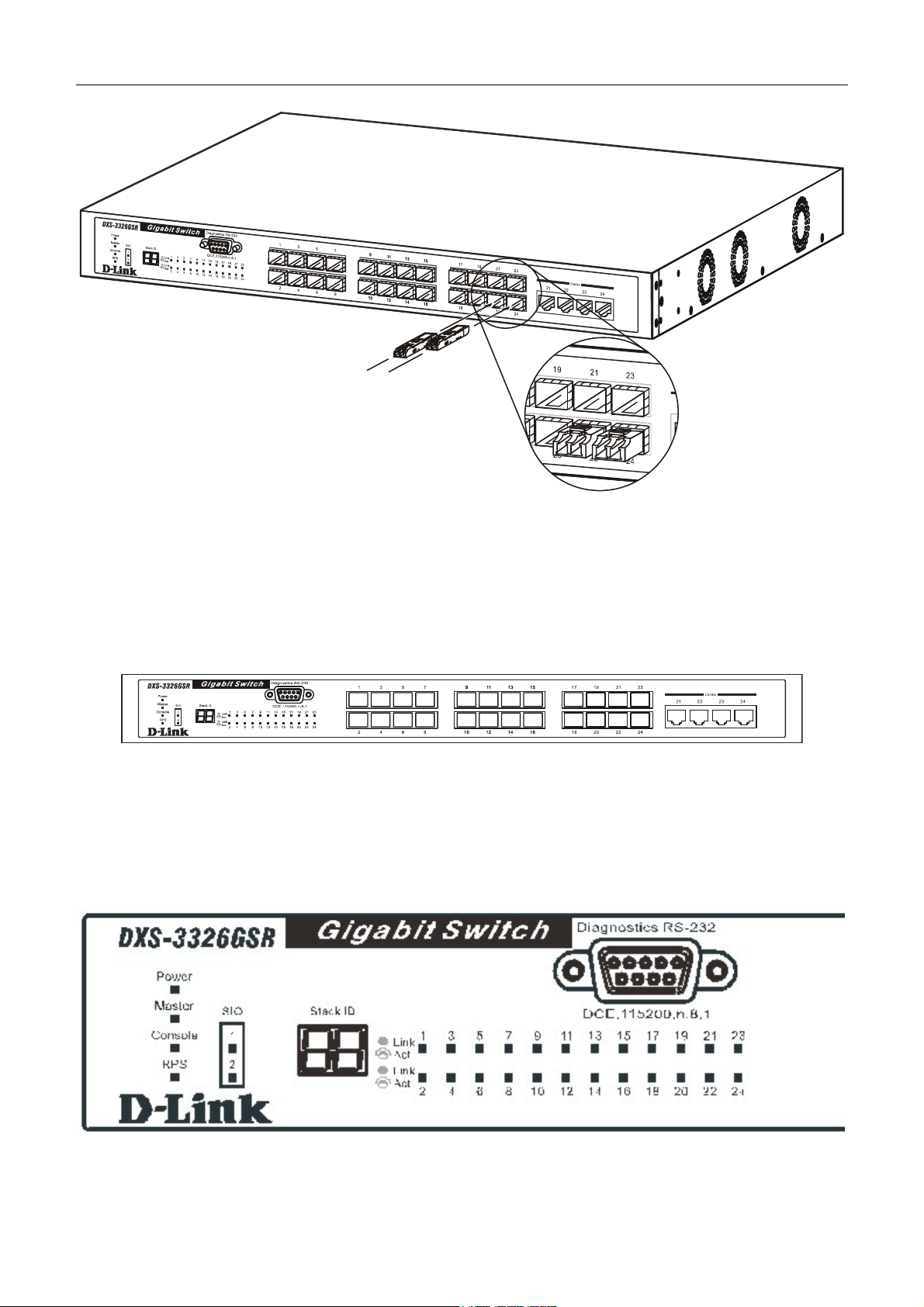
Installing the SFP ports
The Switch is equipped with 24 SFP (Small Form Factor Portable) ports, which are to be used with fiber optical transceiver
cabling in order to uplink various other networking devices for a gigabit link that may span great distances. These 24 SFP
ports support full-duplex transmissions, have auto-negotiation and can be used with DEM-310GT (1000BASE-LX),
DEM-311GT (1000BASE-SX), DEM-314GT (1000BASE-LH) and DEM-315GT (1000BASE-ZX) transceivers. See the
figure below for installing the SFP ports in the Switch.
4
DXS-3326GSR Gigabit Layer 3 Switch
Figure 1- 1. Inserting the fibe-optic transceivers into the DXS-3326GSR
Front-Panel Components
The front panel of the Switch consists of LED indicators for Power, Master, Console RPS, SIO (stacking), and Link/Act
for each port on the Switch. The front panel also includes a seven-segment LED indicating the Stack ID number, as well as
24 SFP ports, four 1000BASE-T gigabit Ethernet ports and a RS-232 DCE console port for Switch management.
DXS-3326GSR
Figure 1- 2. Front Panel View of the DXS-3326GSR as shipped
Comprehensive LED indicators display the status of the Switch and the network.
LED Indicators
The Switch supports LED indicators for Power, Master, Console, RPS, SIO (stacking indicators), and Port LEDs. The
following shows the LED indicators for the Switch along with an explanation of each indicator.
Figure 1- 3. LED Indicators
5

LED Description
DXS-3326GSR Gigabit Layer 3 Switch
Power
Master
Console
RPS
Port LEDs
Stacking Ports
(SIO)
This LED will light green after the Switch is powered on to indicate the ready state of the
device. The indicator is dark when the Switch is powered off.
This LED will light solid green when the Switch is configured to be a master switch of a
switch stack in a ring topology or when it is in use as a stand-alone switch. This LED will
remain dark if the Switch is not configured to be a master switch of a switch stack.
This LED should blink during the Power-On Self Test (POST). When the POST is finished
successfully, the LED goes dark. This indicator will light solid green when the Switch is
being logged into via out-of-band/local console management through the RS-232 console
port in the front of the Switch using a straight-through serial cable.
This LED will light solid amber if the Power-On-Self-Test has failed.
This LED will be lit when the internal power has failed and the RPS has taken over the
power supply to the Switch. Otherwise, it will remain dark.
One row of LEDs for each port is located above the ports on the front panel. The first LED is
for the top port and the second one is for the bottom ports. A solid light denotes activity on
the port while a blinking light indicates a valid link. These LEDs will remain dark if there is
no link/activity on the port.
There are two LEDs in the front of the Switch marked SIO, and they relate to the two 10gigabit stacking ports at the rear of the Switch. These LEDs are marked 1 and 2 and will
light solid green to denote activity on the port, while a blinking light will indicate a valid link.
Stack ID
These two seven segment LEDs display the current switch stack order of the Switch while
in use. Possible numbers to be displayed range from 1-12.
Rear Panel Description
The rear panel of the Switch contains an AC power connector, an optional module slot for uplinking two XFP fiber-optic
ports, two 10-gigabit stacking ports, a redundant power supply connector, and a system fan.
Figure 1- 4. Rear panel view of the Switch
The AC power connector is a standard three-pronged connector that supports the power cord. Plug-in the female connector
of the provided power cord into this socket, and the male side of the cord into a power outlet. The Switch automatically
adjusts its power setting to any supply voltage in the range from 100 ~ 240 VAC at 50 ~ 60 Hz.
The rear panel also includes an outlet for an optional external power supply. When power fails, the optional external RPS
will take over all the power immediately and automatically.
Side Panel Description
The right-hand side panel of the Switch contains three system fans, while the left hand panel includes two heat vents.
The system fans are used to dissipate heat. The sides of the system also provide heat vents to serve the same purpose. Do
not block these openings, and leave at least 6 inches of space at the rear and sides of the Switch for proper ventilation. Be
reminded that without proper heat dissipation and air circulation, system components might overheat, which could lead to
system failure.
6

DXS-3326GSR Gigabit Layer 3 Switch
Figure 1- 5. Side Panels
7

DXS-3326GSR Gigabit Layer 3 Switch
SECTION 2
Installation
Package Contents
Before You Connect to the Network
Installing the Switch Without the Rack
Installing the Switch In a Rack
Optional Module
External Redundant Power System
Package Contents
Open the shipping carton of the Switch and carefully unpack its contents. The carton should contain the following items:
One DXS-3326GSR Stackable Switch •
•
One AC power cord
•
Registration card
•
Mounting kit (two brackets and screws)
•
Four rubber feet with adhesive backing
•
RS-232 console cable
•
One Cable Infinband 4X50CM
•
One CD Kit for User’s Guide/CLI/D-View module
•
One CD Kit for D-View 5.1 Trial version.
•
One Generic QIG
•
One Hardware Installation and Getting Started Guide
•
This Manual
If any item is found missing or damaged, please contact your local D-Link reseller for replacement.
Before You Connect to the Network
The site where you install the Switch may greatly affect its performance. Please follow these guidelines for setting up the
Switch.
•
Install the Switch on a sturdy, level surface that can support at least 6.6 lb. (3 kg) of weight. Do not place heavy
objects on the Switch.
•
The power outlet should be within 1.82 meters (6 feet) of the Switch.
•
Visually inspect the power cord and see that it is fully secured to the AC power port.
•
Make sure that there is proper heat dissipation from and adequate ventilation around the Switch. Leave at least
10 cm (4 inches) of space at the front and rear of the Switch for ventilation.
•
Install the Switch in a fairly cool and dry place for the acceptable temperature and humidity operating ranges.
8
DXS-3326GSR Gigabit Layer 3 Switch
Install the Switch in a site free from strong electromagnetic field generators (such as motors), vibration, dust,
•
and direct exposure to sunlight.
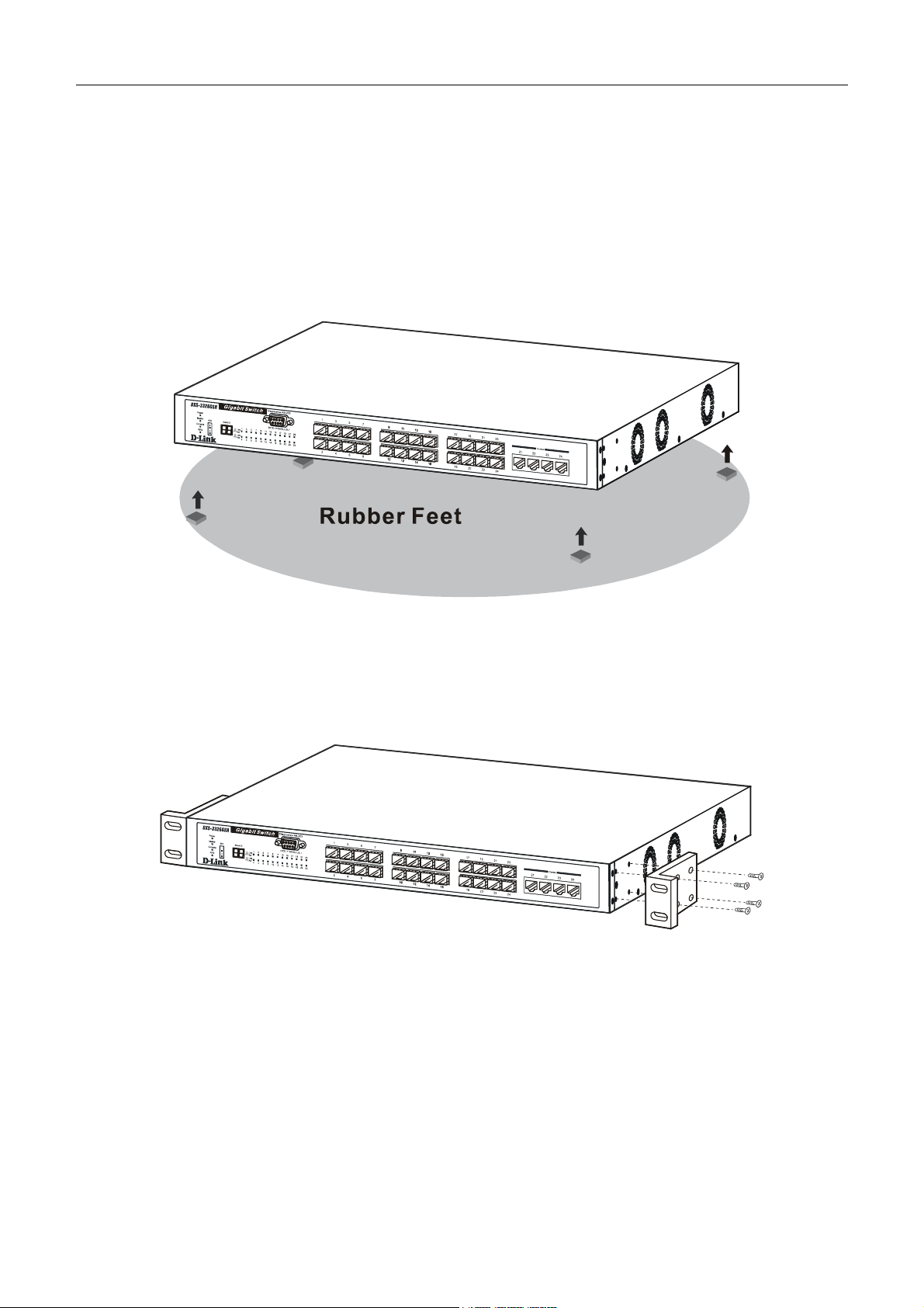
• When installing the Switch on a level surface, attach the rubber feet to the bottom of the device. The rubber feet
cushion the Switch, protect the casing from scratches and prevent it from scratching other surfaces.
Installing the Switch Without the Rack
When installing the Switch on a desktop or shelf, the rubber feet included with the Switch should first be attached. Attach
these cushioning feet on the bottom at each corner of the device. Allow enough ventilation space between the Switch and
any other objects in the vicinity.
Figure 2- 1. Prepare Switch for installation on a desktop or shelf
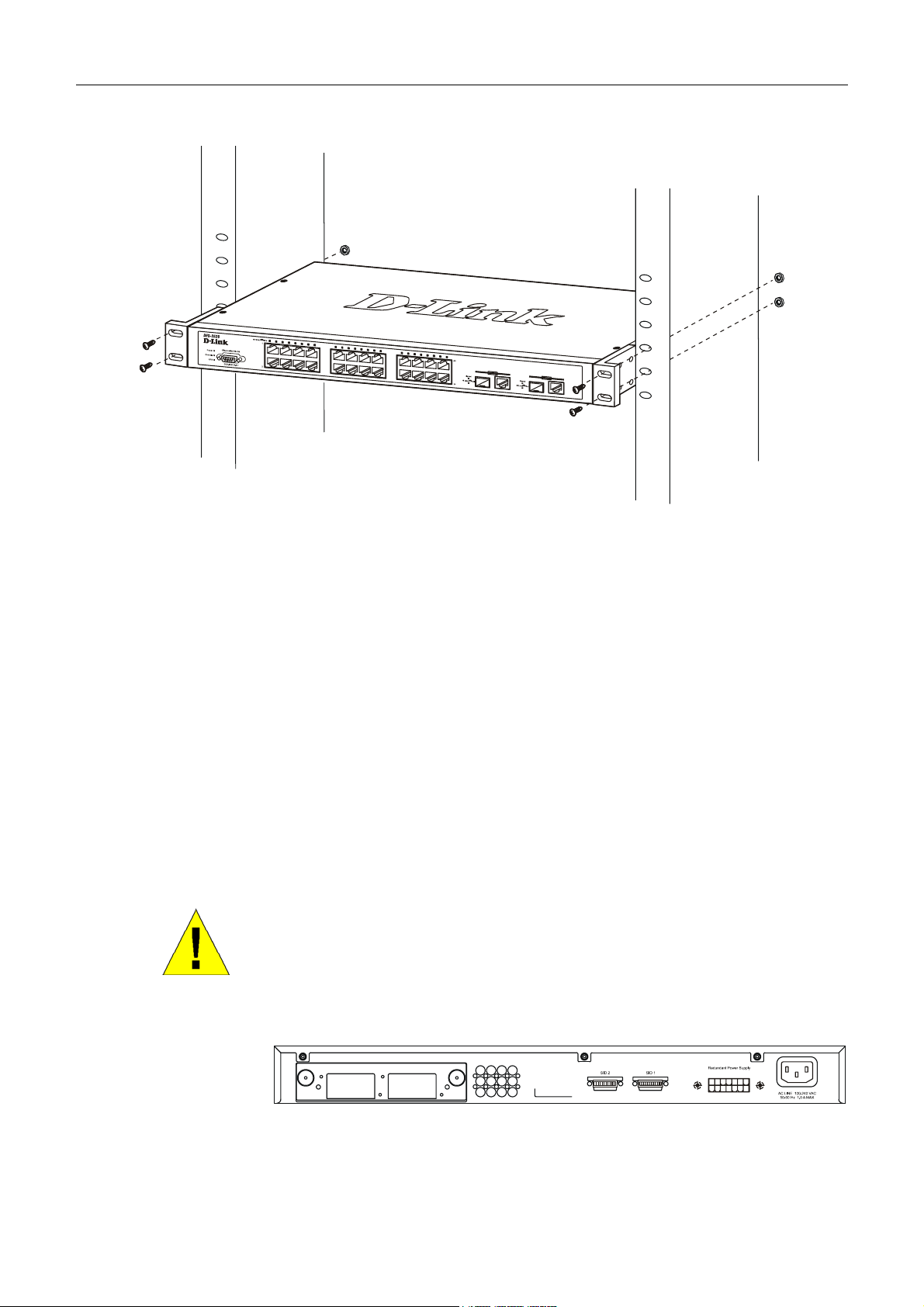
Installing the Switch in a Rack
The Switch can be mounted in a standard 19" rack. Use the following diagrams to guide you.
Figure 2- 2. Fasten mounting brackets to Switch
Fasten the mounting brackets to the Switch using the screws provided. With the brackets attached securely, you can mount
the Switch in a standard rack as shown in Figure 2-3 on the following page.
9
DXS-3326GSR Gigabit Layer 3 Switch
Mounting the Switch in a Standard 19" Rack
Figure 2- 3. Installing Switch in a rack
Power On
Plug one end of the AC power cord into the power connector of the Switch and the other end into the local power source
outlet.
After the Switch is powered on, the LED indicators will momentarily blink. This blinking of the LED indicators represents
a reset of the system.
Power Failure
As a precaution, in the event of a power failure, unplug the Switch. When power is resumed, plug the Switch back in.
Optional Module
At the rear of the DXS-3326GSR resides an optional module slot. This slot may be equipped with a 2-port 10GE XFP
Uplink Module, sold separately. Adding the DEM-420X optional module will allow the administrator to add 2 fiber-optic
ports which will transmit information at a rate of 10 gigabits a second. These two ports are compliant with standard IEEE
802.3ae, support full-duplex transmissions only and can be used with XFP MSA compliant transceivers. To install the
module in the DXS-3326GSR, follow the simple steps listed below.
CAUTION: Before adding the optional module, make sure to disconnect all
power sources connected to the Switch. Failure to do so may result in an
electrical shock that may cause damage, not only to the individual but to
the Switch as well.
At the back of the Switch to the left is the slot for the optional module, as shown in Figure 2-4. This slot should be covered
with a faceplate that can be easily removed by loosening the screws and pulling off the plate.
Optional Module Slot
Figure 2- 4. Optional Module slot at the rear of the DXS-3326GSR
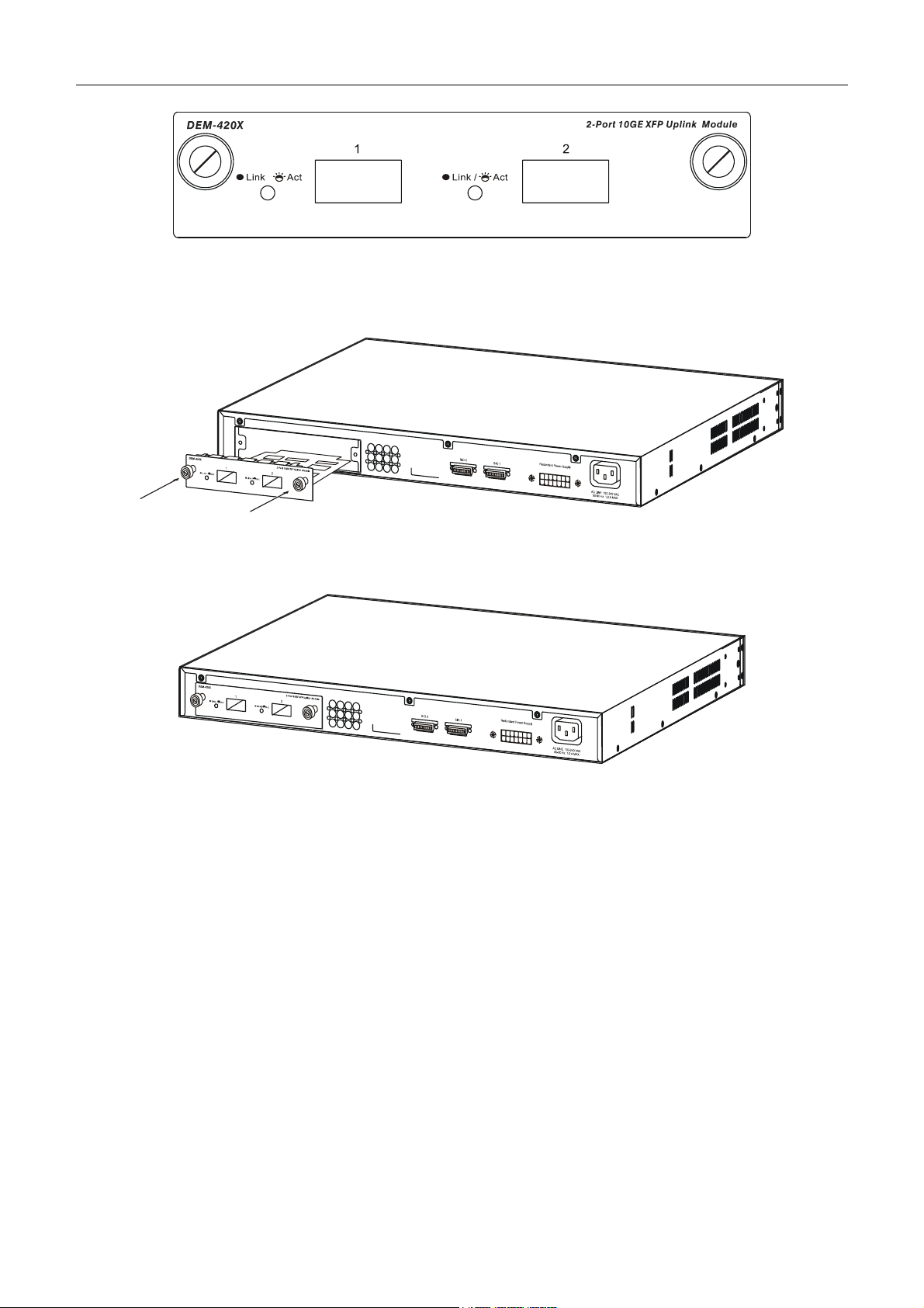
After removing the faceplate, remove the DEM-420X optional module from its box. The front panel should resemble the
drawing represented in the following figure.
10
DXS-3326GSR Gigabit Layer 3 Switch
Figure 2- 5. Front Panel of the DEM-420X
Take the module and gently slide it in to the available slot at the rear of the Switch until it reaches the back, as shown in the
following figure. At the back of the slot are two sets of plugs that must be connected to the module. Gently, but firmly push
in on the module to secure it to the Switch. The module should fit snugly into the corresponding receptors.
Figure 2- 6. Inserting the optional module into the DXS-3326GSR
Now tighten the two screws at adjacent ends of the module into the available screwholes on the Switch. The upgraded
DXS-3326GSR is now ready for use.
Figure 2- 7. DXS-3326GSR with optional module installed.
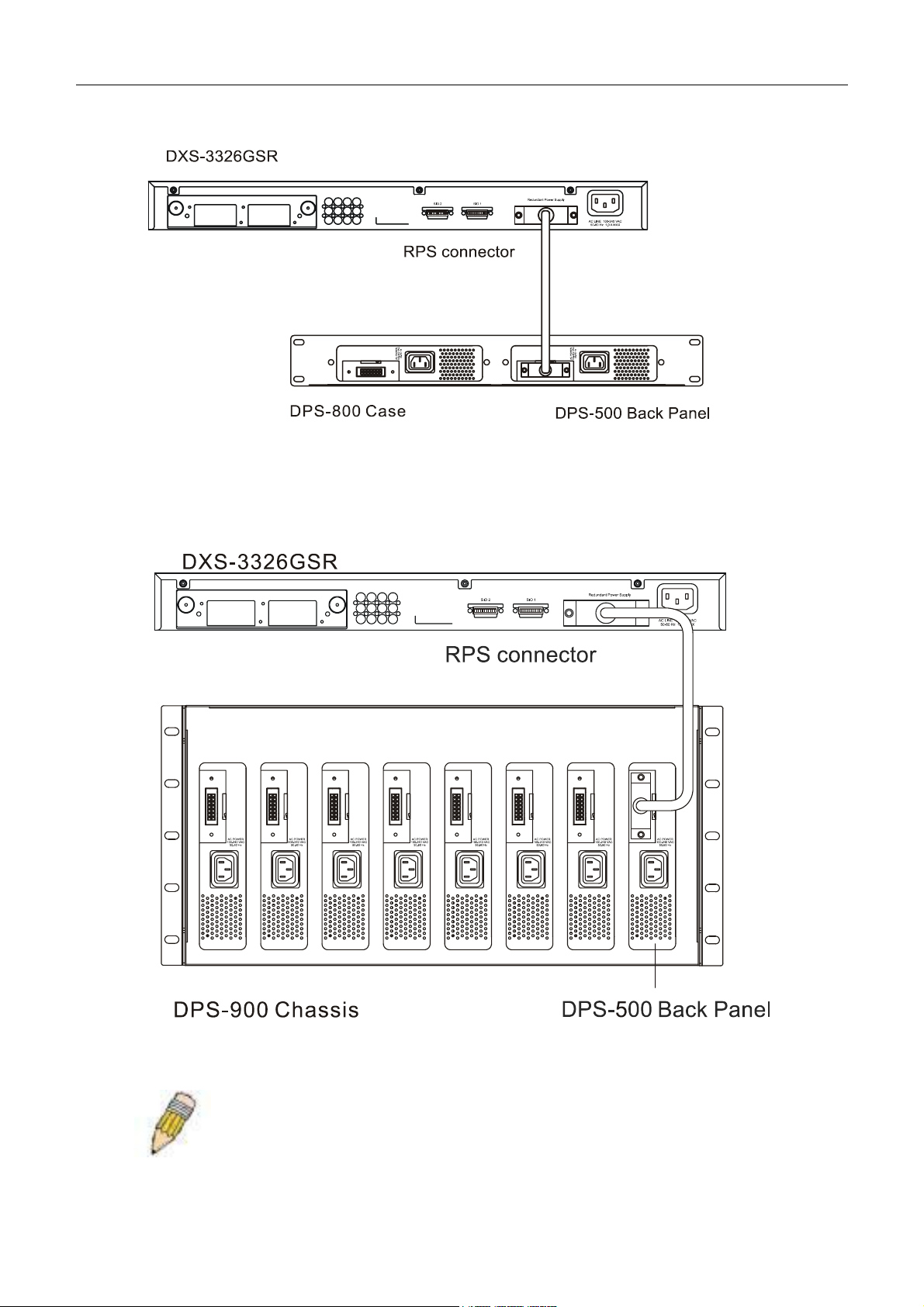
External Redundant Power System
The Switch supports an external redundant power system.
11
DXS-3326GSR Gigabit Layer 3 Switch
Figure 2- 8. The DXS-3326GSR with the DPS-500 Redundant External Power Supply
Figure 2- 9. The DXS-3326GSR with the DPS-900 chassis RPS
NOTE: See the DPS-500 documentation for more information.
12

DXS-3326GSR Gigabit Layer 3 Switch
CAUTION: Do not use the Switch with any redundant power system other
than the DPS-500.
13
DXS-3326GSR Gigabit Layer 3 Switch
Connecting the Switch
Switch To End Node
Switch To Hub or Switch
Connecting To Network Backbone or Server
Stacking and the DXS-3326GSR
NOTE: All 24 high-performance NWay Ethernet ports can support both
MDI-II and MDI-X connections.
Section 3
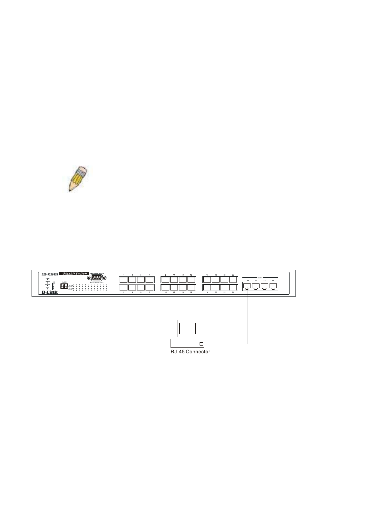
Switch To End Node
End nodes include PCs outfitted with a 10, 100 or 1000 Mbps RJ 45 Ethernet Network Interface Card (NIC) and most
routers.
An end node can be connected to the Switch via a twisted-pair UTP/STP cable. The end node should be connected to any
of the four 1000BASE-T ports of the Switch.
Figure 3- 1. Switch connected to an end node
The Link/Act LEDs for each UTP port will light green or amber when the link is valid. A blinking LED indicates packet
activity on that port.
Switch To Hub or Switch
These connections can be accomplished in a number of ways using a normal cable.
A 10BASE-T hub or switch can be connected to the Switch via a twisted-pair Category 3, 4 or 5 UTP/STP
•
cable.
•
A 100BASE-TX hub or switch can be connected to the Switch via a twisted -pair Category 5 UTP/STP cable.
•
A 1000BASE-T switch can be connected to the Switch via a twisted pair Category 5e UTP/STP cable.
•
A switch supporting a fibre optic uplink can be connected to the Switch’s SFP ports via fiber-optic cabling.
14
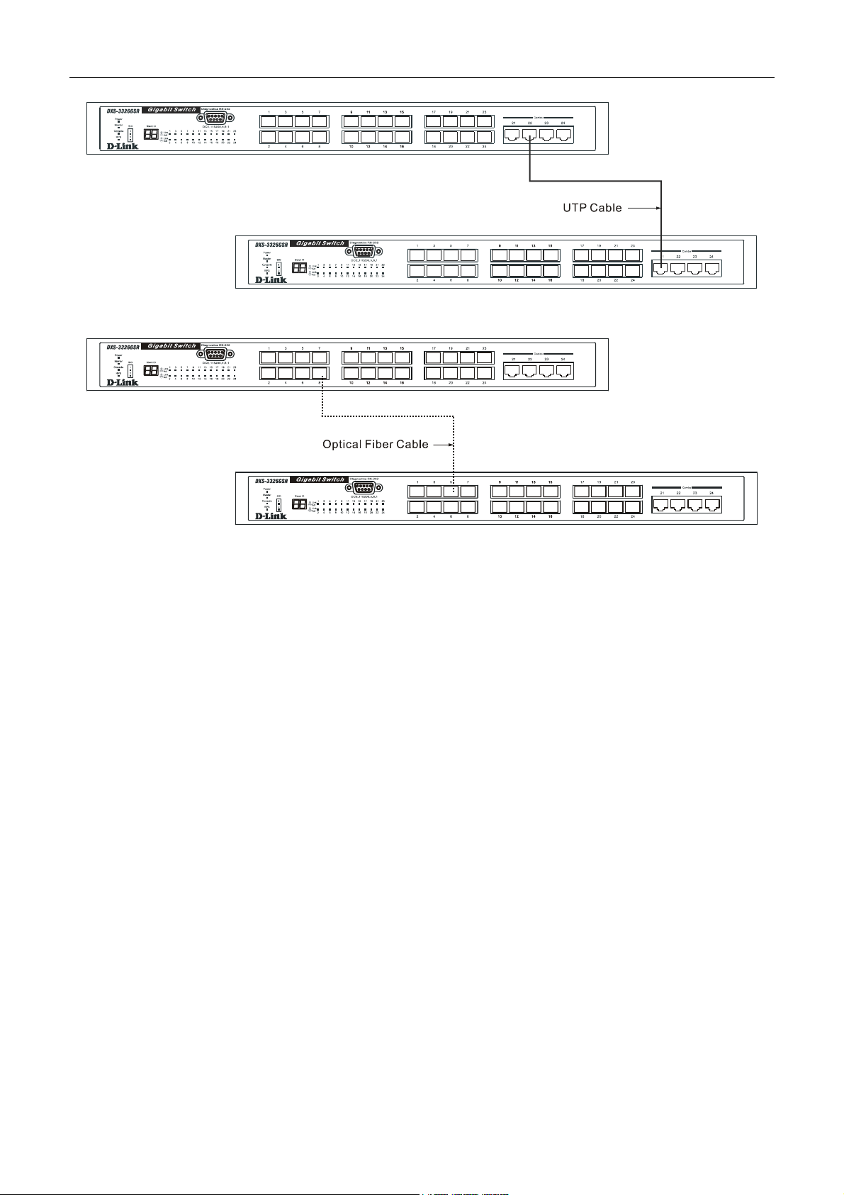
DXS-3326GSR Gigabit Layer 3 Switch
Figure 3- 2. Switch connected to a port on a hub or switch using either a straight or crossover cable-
any normal cable is fine
Figure 3- 3. Switch connected to switch using fiber-optic cabling
Connecting To Network Backbone or Server
The 24 SFP ports and the four combo 1000BASE-T ports are ideal for uplinking to a network backbone, server or server
farm. The copper ports operate at a speed of 1000, 100 or 10Mbps in full or half duplex mode. The fiber-optic ports can
operate at 1000Mbps in full duplex mode only.
Connections to the Gigabit Ethernet ports are made using fiber-optic cable or Category 5e copper cable, depending on the
type of port. A valid connection is indicated when the Link LED is lit.
15
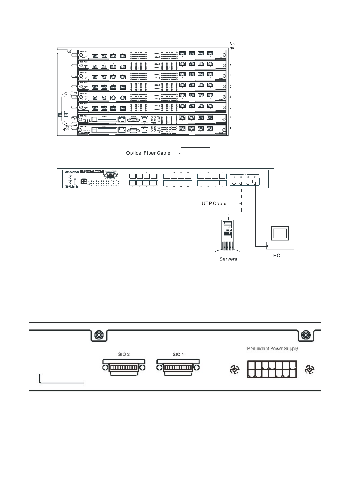
DXS-3326GSR Gigabit Layer 3 Switch
Figure 3- 4. Uplink Connection to a server, PC or switch stack.
Stacking and the DXS-3326GSR
The DXS-3326GSR is equipped with two 10-gigabit stacking ports at the rear of the Switch, as seen in the following
figure. These stacking ports may be used to stack the DXS-3326GSR to a master switch to be used in a switch stack.
Figure 3- 5. SIO 1 and SIO 2 Stacking ports at the rear of the DXS-3326GSR
These two stacking ports, named SIO 1 and SIO 2 can be used with other stacking switches for a scalable stacking solution
of up to 288 ports in a star or ring toplogy. These two stacking ports have corresponding LEDs at the front of the Switch,
labeled SIO 1 and SIO 2 and will light solid green whenever the port is in use. The seven-segment LED Stack ID to the left
of the SIO LEDs on the front of the Switch will display the Stack ID number of the Switch in a switch stack.
16
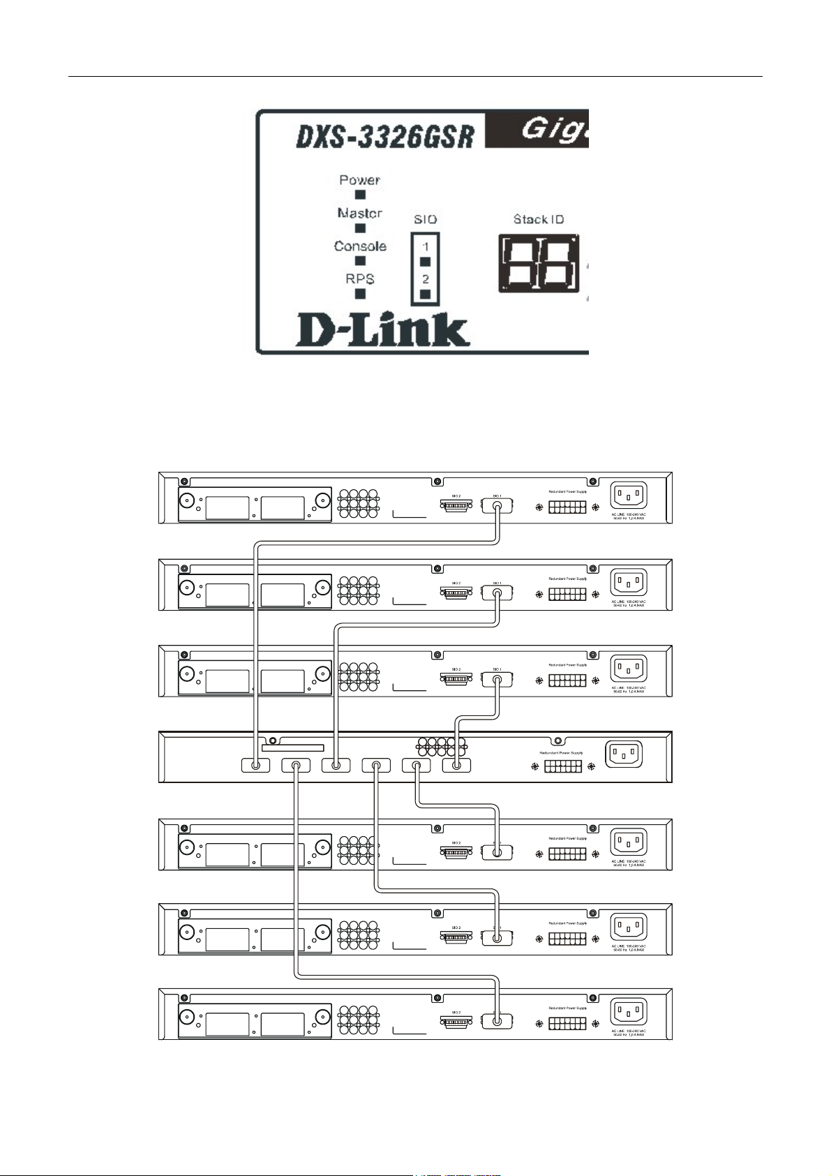
DXS-3326GSR Gigabit Layer 3 Switch
Figure 3- 6. Stacking LEDs at the front of the DXS-3326GSR
The Switch can be stacked in a star or ring topology, as previously mentioned. For a star architecture, only one of the two
Gigabit stacking ports will be in use. This port will be connected to the master switch of the switch stack and will act as a
slave switch of the stack. The administrator may use either of the two available stacking ports to achieve this arcitecture.
See the following diagram for an example of stacking in a star architecture.
Figure 3- 7. Stacking in a Star Architecture
17
 Loading...