

Page 1

CLI Guide
Product Model : DXS-3200 Series
L2 Stackable Gigabit Mngd. Switch with Optional 10Gig Uplinks
Release 1
©Copyright 2005. All rights reserved.
Page 2

Table of Contents
Section 1.Using the CLI......................................................................................................12
Overview........................................................................................................................................12
CLI Command Modes....................................................................................................................13
Introduction..............................................................................................................................................13
User EXEC Mode ....................................................................................................................................14
Privileged EXEC Mode............................................................................................................................14
Global Configuration Mode......................................................................................................................14
Interface Configuration and Specific Configuration Modes............................................... ... ....................15
Starting the CLI..............................................................................................................................15
Editing Features ............................................................................................................................16
Entering Commands................................................................................................................................16
Terminal Command Buffer................................................................................................................................. 17
Negating the Effect of Commands..................................................................................................................... 17
Command Completion ....................................................................................................................................... 17
Nomenclature..................................................................................................................................................... 17
Keyboard Shortcuts............................................................................................................................................ 18
CLI Command Conventions............................................................................................................................... 18
Copying and Pasting Text........................................................................................................................18
Section 2.AAA Commands................................................................................................. 20
aaa authentication login.......................................................................................................................20
aaa authentication enable....................................................................................................................22
login authentication..............................................................................................................................24
enable authentication...........................................................................................................................25
ip http authentication......................................................................... ... ... .............................................26
ip https authentication.................................................................................................... ... ...................27
show authentication methods...............................................................................................................28
password..............................................................................................................................................29
enable password..................................................................................................................................30
username.............................................................................................................................................31
Section 3.ACL Commands................................................................................................. 32
stack light unit ......................................................................................................................................32
ip access-list........................... .... .......................................................... ... ... ..........................................33
permit (ip).............................................................................................................................................34
deny (IP)...............................................................................................................................................37
mac access-list........................... ... .......................................................... ... ... .......................................39
permit (MAC)........................................................................................................................................40
deny (MAC)..........................................................................................................................................41
service acl.................................. ... ... ... .... .............................................................................................42
show access-lists.................................................................................................................................43
show interfaces access-lists.................................................................................................................44
Page 1
Page 3

D-Link CLI Reference Guide
Section 4.Address Table Commands................................................................................ 46
bridge address..................................................................................................................................... 46
bridge multicast filtering....................................................................................................................... 47
bridge multicast address...................................................................................................................... 48
bridge multicast forbidden address...................................................................................................... 49
bridge multicast forward-all.................................................................................................................. 50
bridge multicast forbidden forward-all.................................................................................................. 51
bridge aging-time................................................................................................................................. 52
clear bridge.......................................................................................................................................... 53
port security......................................................................................................................................... 54
port security mode...............................................................................................................................55
port security routed secure-address.................................................................................................... 56
show bridge address-table .................................................................................................................. 57
show bridge address-table static......................................................................................................... 58
show bridge address-table count......................................................................................................... 59
show bridge multicast address-table ................................................................................................... 60
show bridge multicast filtering ............................................................................................................. 62
show ports security.............................................................................................................................. 63
show ports security addresses......................... ... ... ... .... ... ................................................................... 65
Section 5.Clock Commands............................................................................................... 68
clock set.................. ... .......................................................... ... .... ......................................................... 68
clock source.................. ... .... ... ... ... ........................................................... ... ... ... ... .... ... ......................... 69
clock timezone........................................ ... .... ... ... ... ... .... ... ... ... ............................................................. 70
clock summer-time ................................................. ... .... ......................................................................71
sntp authentication-key........................................................................................................................ 73
sntp authenticate................................................................................................................................. 74
sntp trusted-key................................................................................................................................... 75
sntp client poll timer............................................................................................................................. 76
sntp broadcast client enable................................................................................................................ 77
sntp anycast client enable ................................................................................................................... 78
sntp client enable (Interface) ............................................................................................................... 79
sntp unicast client enable.................................................................................................................... 80
sntp unicast client poll ......................................................................................................................... 81
sntp server........................................................................................................................................... 82
show clock........................................................................................................................................... 83
show sntp configuration....................................................................................................................... 84
show sntp status.................................................................................................................................. 85
Section 6.Configuration and Image File Commands....................................................... 86
copy..................................................................................................................................................... 86
delete................................................................................................................................................... 89
boot system......................................................................................................................................... 90
show running-config ............................................................................................................................ 91
show startup-config ............................................................................................................................. 92
show bootvar....................................................................................................................................... 93
Page 2
Page 4

Section 7.Ethernet Configuration Commands ................................................................. 94
interface ethernet.................................................................................................................................94
interface range ethernet.......................................................................................................................95
shutdown..............................................................................................................................................96
description............................................................................................................................................97
speed ...................................................................................................................................................98
duplex...................................................................................................................................................99
negotiation..........................................................................................................................................100
flowcontrol..........................................................................................................................................101
mdix....................................................................................................................................................102
back-pressure ....................................................................................................................................103
port jumbo-frame................................................................................................................................104
clear counters.....................................................................................................................................105
set interface active.............................................................................................................................106
show interfaces advertise...................................................................................................................107
show interfaces configuration.............................................................................................................109
show interfaces status........................................................................................................................111
show interfaces description................................................................................................................113
show interfaces counters ...................................................................................................................114
show ports jumbo-frame.....................................................................................................................117
port storm-control include-multicast (GC) ..........................................................................................118
port storm-control include-multicast (IC)............................................................................................119
port storm-control broadcast enable ..................................................................................................120
port storm-control broadcast rate.......................................................................................................121
show ports storm-control....................................................................................................................122
Section 8.GVRP Commands ............................................................................................ 124
gvrp enable (Global)...........................................................................................................................124
gvrp enable (Interface).......................................................................................................................125
garp timer...........................................................................................................................................126
gvrp vlan-creation-forbid ....................................................................................................................127
gvrp registration-forbid.......................................................................................................................128
clear gvrp statistics.............................................................................................................................129
show gvrp configuration.....................................................................................................................130
show gvrp statistics............................................................................................................................131
show gvrp error-statistics...................................................................................................................132
Section 9.IGMP Snooping Commands............................................................................ 134
ip igmp snooping (Global)..................................................................................................................134
ip igmp snooping (Interface)...............................................................................................................135
ip igmp snooping mrouter learn-pim-dvmrp .......................................................................................136
ip igmp snooping host-time-out..........................................................................................................137
ip igmp snooping mrouter-time-out ....................................................................................................138
ip igmp snooping leave-time-out........................................................................................................139
show ip igmp snooping mrouter.........................................................................................................140
show ip igmp snooping interface........................................................................................................141
show ip igmp snooping groups...........................................................................................................142
Page 3
Page 5

D-Link CLI Reference Guide
Section 10.IP Addressing Commands............................................................................ 144
ip address...................................................................... ... ... ... ........................................................... 144
ip address dhcp................................ ... ... ... .... ... ... .......................................................... .................... 145
ip default-gateway ..................................... .... ... ... ... ... .... .................................................................... 146
show ip interface................................................................................................................................ 147
arp ..................................................................................................................................................... 148
arp timeout......................................................................................................................................... 149
ip proxy-arp................... ... .... .......................................................... ... ... .............................................. 150
clear arp-cache.................................................................................................................................. 151
show arp............................................................................................................................................ 152
interface ip.........................................................................................................................................153
directed-broadcast............................................................................................................................. 154
broadcast-address............................................................................................................................. 155
helper-address................................................................................................................................... 156
ip domain-lookup.............................. ... ... ... .... ... ... ... ... .... ... ................................................................. 158
ip domain-name............................................. ... ... ... ... .... ... ... ... ........................................................... 159
ip name-server................. .... ... ... ... ........................................................... ... ... ... ... .... ... ... .................... 160
ip host..................................................................... ........................................................................... 161
clear host...........................................................................................................................................162
clear host dhcp.................................................................................................................................. 163
show hosts.........................................................................................................................................164
Section 11.IP Routing Commands .................................................................................. 166
ip route.................... ... .......................................................... .............................................................. 166
show ip route..................................................................................................................................... 167
Section 12.LACP Commands........................................................................................... 170
lacp system-priority.......... .... ... ... .......................................................... .... ... ... ... ... .... .......................... 170
lacp port-priority...................................... ... .... .......................................................... ... ....................... 171
lacp timeout............................ ... ... .... ... ... .......................................................... ... .... ... ....................... 172
show lacp ethernet ............................................................................................................................ 173
show lacp port-channel...................................................................................................................... 175
Section 13.Line Commands............................................................................................. 176
line..................................................................................................................................................... 176
speed................................................................................................................................................. 177
autobaud............................................................................................................................................ 178
exec-timeout...................................................................................................................................... 179
history................................................................................................................................................ 180
history size.............. ... ... .......................................................... .... ... .................................................... 181
terminal history.................................................................................................................................. 182
terminal history size........................................................................................................................... 183
show line............................................................................................................................................ 184
Section 14.Management ACL Commands...................................................................... 186
management access-list.................................................................................................................... 186
permit (Management)........................................................................................................................ 188
Page 4
Page 6

deny (Management)...........................................................................................................................189
management access-class.................................................................................................................190
show management access-list...........................................................................................................191
show management access-class .......................................................................................................192
Section 15.PHY Diagnostics Commands........................................................................ 194
test copper-port tdr. ... .... ... ... ...............................................................................................................194
show copper-ports tdr ........................................................................................................................195
show copper-ports cable-length.........................................................................................................196
show fiber-ports optical-transceiver ...................................................................................................197
Section 16.Port Channel Commands.............................................................................. 200
interface port-channel ........................................................................................................................200
interface range port-channel..............................................................................................................201
channel-group....................................................................................................................................202
show interfaces port-channel.............................................................................................................203
Section 17.Port Monitor Commands...............................................................................204
port monitor........................................................................................................................................204
port monitor vlan-tagging ...................................................................................................................205
show ports monitor.............................................................................................................................206
Section 18.Power over Ethernet Commands .................................................................208
power inline............................ .... ... ... .......................................................... ... .... ... ..............................208
power inline powered-device............................... .... ... ... ... .... ... ... ... .... ... ... ... ... .... ... ..............................209
power inline priority............................................................................................................................210
power inline usage-threshold........................................... .... ... ...........................................................211
power inline traps enable...................................................................................................................212
show power inline...............................................................................................................................213
Section 19.QoS Commands............................................................................................. 216
qos .....................................................................................................................................................216
show qos............................................................................................................................................217
class-map...........................................................................................................................................218
show class-map .................................................................................................................................219
match access-group................................................... ... ... .... ..............................................................220
policy-map..........................................................................................................................................221
class...................................................................................................................................................222
show policy-map ................................................................................................................................223
trust cos-dscp.....................................................................................................................................224
set ......................................................................................................................................................225
police..................................................................................................................................................226
service-policy .....................................................................................................................................227
qos aggregate-policer ......... ... ........................................................... ... ... ... ... .... ... ... ...........................228
show qos aggregate-policer...............................................................................................................230
police aggregate.................................................................................................................................231
wrr-queue cos-map............................................................................................................................232
Page 5
Page 7

D-Link CLI Reference Guide
wrr-queue bandwidth......................................................................................................................... 233
priority-queue out num-of-queues ..................................................................................................... 234
traffic-shape....................................................................................................................................... 235
show qos interface............................................................................................................................. 236
qos wrr-queue threshold................................................ ... ................................................................. 238
qos map policed-dscp....................... ... ... ... .... ... ... ... ... .... .................................................................... 239
qos map dscp-queue................. ... .... ... ... ... .... ... ... ... ... .... ... ... .............................................................. 240
qos trust (Global).......... ... .... ... ... .......................................................... .... ... ... ... ... .... ... ....................... 241
qos trust (Interface) ............................................. ... ... .... ... ... ... .... ... ... ... .............................................. 242
qos cos................................... .......................................................... ... .... .......................................... 243
qos dscp-mutation .................. ... ... ........................................................... ... ... .................................... 244
qos map dscp-mutation................................. ... ... ... ... .... ... ... ... .... ... .................................................... 245
Section 20.Radius Commands ........................................................................................ 246
radius-server host.............................................................................................................................. 246
radius-server key............................................................................................................................... 248
radius-server retransmit..................................................................................................................... 249
radius-server source-ip...................................................................................................................... 250
radius-server timeout......................................................................................................................... 251
radius-server deadtime...................................................................................................................... 252
show radius-servers .......................................................................................................................... 253
Section 21.RMON Commands ......................................................................................... 254
show rmon statistics .......................................................................................................................... 254
rmon collection history............................................ ... .... ... ... ... .... ... ... ... .... ... ....................................... 256
show rmon collection history ............................................................................................................. 257
show rmon history ............................................................................................................................. 258
rmon alarm ................................................ .... ... ... ... ... ........................................................................ 261
show rmon alarm-table...................................................................................................................... 263
show rmon alarm............................................................................................................................... 264
rmon event.................... ... .... ... .......................................................... ... .... ... ... ... ... .............................. 266
show rmon events ............................................................................................................................. 267
show rmon log ................................................................................................................................... 268
rmon table-size............. ... ........................................................... ... ... ... .............................................. 270
Section 22.SNMP Commands.......................................................................................... 272
snmp-server community.................................................................................................................... 272
snmp-server view ................................................... ... .... ... ... ... .... ... ... ... .... .......................................... 274
snmp-server group ............................................................................................................................ 275
snmp-server user............. .... .......................................................... ... ... .... .......................................... 276
snmp-server engineID local............................................................................................................... 278
snmp-server enable traps.................................................................................................................. 280
snmp-server filter............................................................................................................................... 281
snmp-server host............................................................................................................................... 282
snmp-server v3-host.......................................................................................................................... 283
snmp-server trap authentication........................................................................................................ 284
snmp-server contact.......................................................................................................................... 285
Page 6
Page 8

snmp-server location..................................................... ... .... ... ... ........................................................286
snmp-server set .................................................................................................................................287
show snmp.........................................................................................................................................288
show snmp engineid ..........................................................................................................................290
show snmp views...............................................................................................................................291
show snmp groups.............................................................................................................................292
show snmp filters ...............................................................................................................................294
show snmp users...............................................................................................................................295
Section 23.Spanning-Tree Commands ........................................................................... 296
spanning-tree.....................................................................................................................................296
spanning-tree mode......................................... ... .... ... ... ... .... ... ... ........................................................297
spanning-tree forward-time................................................................................................................298
spanning-tree hello-time.....................................................................................................................299
spanning-tree max-age......................................................................................................................300
spanning-tree priority .......... ... .... ... ... ... .... ... ........................................................................................301
spanning-tree disable .... ... ... .......................................................... .... ... ... ... ... .... .................................302
spanning-tree cost............................... .... ... ... ... ... ........................................................... ....................303
spanning-tree port-priority..................................................................................................................304
spanning-tree portfast........................................................................................................................305
spanning-tree link-type............................................... ... ... .... ... ... ... .... ... ..............................................306
spanning-tree pathcost method..........................................................................................................307
spanning-tree bpdu....................................... ... ... .... ... ... ... .... ..............................................................308
clear spanning-tree detected-protocols..............................................................................................309
spanning-tree mst priority........................ ... ........................................................................................310
spanning-tree mst max-hops............................ ... .... ... ... ... .... ..............................................................311
spanning-tree mst port-priority...........................................................................................................312
spanning-tree mst cost............................................... ... ... .... ..............................................................313
spanning-tree mst configuration.........................................................................................................314
instance (mst).....................................................................................................................................315
name (mst).......................... ... .... ... .......................................................... ... ... .....................................316
revision (mst)......................................................................................................................................317
show (mst)..........................................................................................................................................318
exit (mst) ............................................................................................................................................319
abort (mst) . .......................................................... .... ... ... .....................................................................320
spanning-tree guard root.. ..................................................................................................................321
show spanning-tree............................................................................................................................322
Section 24.SSH Commands............................................................................................. 334
ip ssh port...................................... ... ... .... ... ... .......................................................... ... ........................334
ip ssh server.. ... ... ... ... ........................................................... ... ... ... .... ... ... ...........................................335
crypto key generate dsa.....................................................................................................................336
crypto key generate rsa......................................................................................................................337
ip ssh pubkey-auth........................... ... .... ... ... ... ... ........................................................... ... .................338
crypto key pubkey-chain ssh..............................................................................................................339
user-key .............................................................................................................................................340
key-string............................................................................................................................................341
Page 7
Page 9

D-Link CLI Reference Guide
show ip ssh........................................................................................................................................ 343
show crypto key mypubkey ............................................................................................................... 344
show crypto key pubkey-chain ssh.................................................................................................... 345
Section 25.Syslog Commands......................................................................................... 346
logging on.......................................................................................................................................... 346
logging............................................................................................................................................... 347
logging console.................................................................................................................................. 348
logging buffered................................................................................................................................. 349
logging buffered size ......................................................................................................................... 350
clear logging...................................................................................................................................... 351
logging file ......................................................................................................................................... 352
clear logging file................................................................................................................................. 353
aaa logging login ...............................................................................................................................354
file-system logging............................................................................................................................. 355
management logging......................................................................................................................... 356
show logging......................................................................................................................................357
show logging file................................................................................................................................359
show syslog-servers.......................................................................................................................... 361
Section 26.System Management Commands................................................................. 362
ping.................................................................................................................................................... 362
traceroute .......................................................................................................................................... 364
telnet.................................................................................................................................................. 366
resume............................................................................................................................................... 369
reload................................................................................................................................................. 370
hostname........................................................................................................................................... 371
stack master...................................................................................................................................... 372
stack reload....................................................................................................................................... 373
stack display-order ............................................................................................................................ 374
stack light unit.................................................................................................................................... 375
show stack......................................................................................................................................... 376
set system mode ............................................................................................................................... 378
show system mode............................................................................................................................ 379
show users ........................................................................................................................................ 380
show sessions................................................................................................................................... 381
show system...................................................................................................................................... 382
show version......................................................................................................................................383
service cpu-utilization ................... .... ... .......................................................... ... ... .............................. 384
show cpu utilization ........................................................................................................................... 385
Section 27.TACACS+ Commands ................................................................................... 386
tacacs-server host............................................................................................................................. 386
tacacs-server key ... ... ... ... .... .............................................................................................................. 388
tacacs-server timeout................................ .... ... ... ... ... .... ... ... ... .... ... ... ... .............................................. 389
tacacs-server source-ip..................................................................................................................... 390
show tacacs....................................................................................................................................... 391
Page 8
Page 10

Section 28.User Interface Commands ............................................................................392
do.......................................................................................................................................................392
enable ................................................................................................................................................392
disable................................................................................................................................................394
login....................................................................................................................................................395
configure ............................................................................................................................................396
exit (Configuration).............................................................................................................................397
exit......................................................................................................................................................398
end.....................................................................................................................................................399
help ....................................................................................................................................................400
terminal data-dump............................................................................................................................401
show history.......................................................................................................................................402
show privilege ....................................................................................................................................403
Section 29.VLAN Commands........................................................................................... 404
vlan database... ... ... ... ........................................................... ... ... ... .... ... ... ...........................................404
vlan.....................................................................................................................................................405
interface vlan......................................................................................................................................406
interface range vlan............................................................................................................................407
name..................................................................................................................................................408
switchport protected...........................................................................................................................409
switchport mode.................................................................................................................................410
switchport access vlan.......................................................................................................................411
map protocol protocols-group ............................................................................................................412
switchport trunk allowed vlan........................ ... ... ...............................................................................413
switchport trunk native vlan................................................................................................................414
switchport general allowed vlan....................................... .... ... ... ... .....................................................415
switchport general map protocols-group vlan ....................................................................................416
switchport general pvid ......................................................................................................................417
switchport general ingress-filtering disable ........................................................................................418
switchport general acceptable-frame-type tagged-only .....................................................................419
switchport forbidden vlan ........................................................ ... ... .....................................................420
ip internal-usage-vlan .... ... ... ... .... ... ... ... .......................................................... .... ... ... ... .... ... .................421
show vlan...........................................................................................................................................422
show vlan internal usage....................................................................................................................423
show interfaces switchport.................................................................................................................424
Section 30.Web Server Commands................................................................................. 428
ip http server .............................................................. ........................................................................428
ip http port........................................... .... ... .......................................................... ... ... ........................429
ip https server................................ ... ... .... .......................................................... ... ... ... ........................430
ip https port ............... ........................................................... ... ... ........................................................431
crypto certificate generate....................................................... ... ... .... ... ... ... ... .... .................................432
crypto certificate request..................... .... ... ... ... ... .... ... ... ... .... ... ... ........................................................433
crypto certificate import.................... ... .... ... ... ... ... .... ... ... ... .... ..............................................................435
ip https certificate.......................................... ... ... .... ... ... ... .... ... ...........................................................436
show crypto certificate mycertificate ..................................................................................................437
Page 9
Page 11

D-Link CLI Reference Guide
show ip http ....................................................................................................................................... 438
show ip https......................................................................................................................................439
Section 31.802.1x Commands ......................................................................................... 440
aaa authentication dot1x default........................................................................................................ 440
dot1x system-auth-control......................... .... ... ... ... ... .... .................................................................... 441
dot1x port-control................. .......................................................... ... ... .... ... ... ... ... .............................. 442
dot1x re-authentication........... ........................................................................................................... 443
dot1x timeout re-authperiod................. ... ... .... ... ... ... ... .... ... ... ... .... ... ... ... .............................................. 444
dot1x re-authenticate........................................ ... ... ... .... ... ... ... .... ....................................................... 445
dot1x timeout quiet-period................................................................................................................. 446
dot1x timeout tx-period........ ... ... ... ........................................................... ... ... ... ... .... ... ....................... 447
dot1x max-req.................................................................................................................................... 448
dot1x timeout supp-timeout.............................. ... ... ... .... ... ... ... .... ... ... ... .... ... ... ... ................................. 449
dot1x timeout server-timeout..... ... .... ... .......................................................... ... ... .... ... ... ... .... ............. 450
show dot1x ........................................................................................................................................ 451
show dot1x users...............................................................................................................................454
show dot1x statistics.......................................................................................................................... 456
ADVANCED FEATURES .................................... ... .......................................................... .... ... ... ....... 458
dot1x auth-not-req ............................................................................................................................. 458
dot1x multiple-hosts........................................................................................................................... 459
dot1x single-host-violation................................................................................................................. 460
dot1x guest-vlan .................. ... ... ... .... ... ... ... .... .......................................................... ... ... .................... 461
dot1x guest-vlan enable ................................................ ... ... ... .... ... ... ................................................. 462
show dot1x advanced........................................................................................................................ 463
Page 10
Page 12

Page 11
Page 13

D-Link CLI Reference Guide
Section 1. Using the CLI
Overview
This document describes the Command Line Interface (CLI) used to manage the D-Link family of managed
devices. This family includes:
DXS-3250 – Stackabel device with 48-port 10/100/1000BASE-T, 4 FSP ports, one Infiniband port and a 10G port.
DXS-3227P – Stackabel
two 10G ports.
DXS-3227 – Stackabel device with 24-port 10/100/1000BASE-T, with one XFP fixed port and two 10G ports.
The DXS-3250, DXS-3227P and DXS-3227 can operate as standalone systems, or can be stacked together in the
same system.
Most of the CLI commands are applicable to all devices.
This chapter describes how to start using the CLI and the CLI command editing features.
Power over Ethernet device with 24-port 10/100/1000BASE-T, with one XFP fixed port and
Page 12
Page 14
Using the CLI
CLI Command Modes
CLI Command Modes
Introduction
To assist in configuring the device, the Command Line In terface (CLI) is divided into different command modes.
Each command mode has its own set of specific commands. Entering a question mark "?" at the system prompt
(console prompt) displays a list of commands available for that particular command mode.
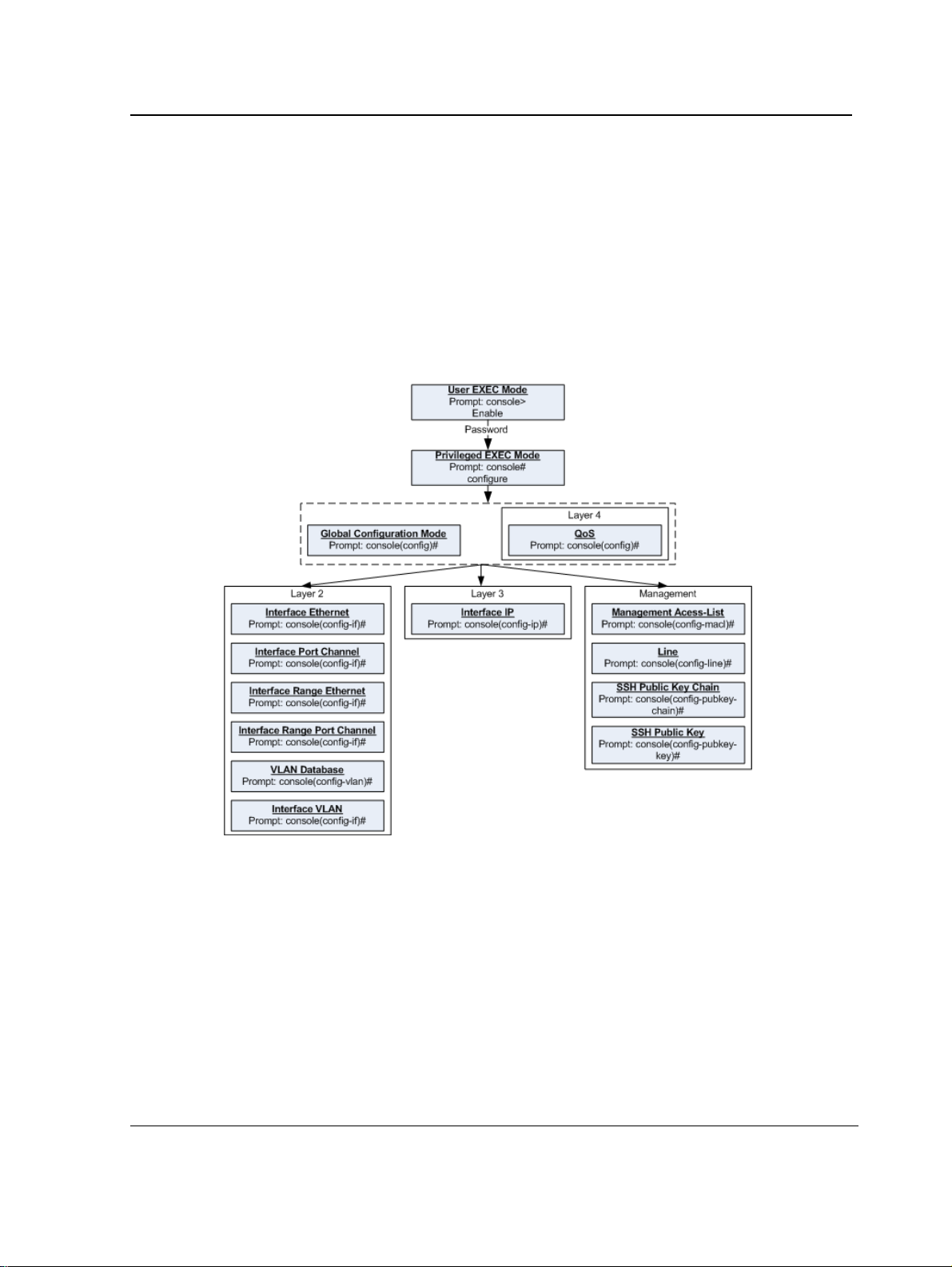
From each mode a specific command is used to navigate from one command mode to another. The standard
order to access the modes is as follows: User EXEC mode, Privileged EXEC mode, Glob al Configuration mode,
and Interface Configuration mode. The following figure illustrates the command mode access path.
When starting a session, the initial mode is the User EXEC mode. Only a limited subset of commands are
available in User EXEC mode. This level is reserved for tasks that do not change the configuration. To enter the
next level, the Privileged EXEC mode, a password is required.
The Privileged EXEC mode gives access to commands that are restricted on User EXEC mode and provides
access to the device Configuration mode.
The Global Configuration mode manages the device configuration on a global level.
The Interface Configuration mode configures specific interfaces in the device.
Page 13
Page 15

D-Link CLI Reference Guide
User EXEC Mode
After logging into the device, the user is automatically in User EXEC command mode unless the user is defined as
a privileged user. In general, the User EXEC commands allow the user to perform basic tests, and list system
information.
The user-level prompt consists of the device host name followed by the angle bracket (>).
Console>
The default host name is Console unless it has been changed using the hostname command in the Global
Configuration mode.
Privileged EXEC Mode
Privileged access is password protected to prevent unauthorized use because many of the privileged commands
set operating system parameters. The password is not displayed on the screen and is case sensitive.
Privileged users enter directly into the Privileged EXEC mode. To enter the Privileged EXEC mode from the User
EXEC mode, perform the following steps:
1. At the prompt enter the enable command and press <Enter>. A password prompt is displayed.
2. Enter the password and press <Enter>. The password is displayed as *. The Privileged EXEC mode prompt
is displayed. The Privileged EXEC mode prompt consists of the device host name followed by #.
Console#
To return from the Privileged EXEC mode to the User EXEC mode, use the disable command. The following
example illustrates how to access the Privileged EXEC mode and return to the User EXEC mode:
Console>
Enter Password: ******
Console#
Console#
Console>
The exit command is used to return from any mode to the previous mode except when returning to the User
EXEC mode from the Privileged EXEC mode. For example, the exit command is used to return from th e Int erface
Configuration mode to the Global Configuration mode.
enable
disable
Global Configuration Mode
Global Configuration mode commands apply to features that affect the system as a whole, rather than just a
specific interface. The configure Privileged EXEC mode command is used to enter the Global Configuration
mode.
To enter the Global Configuration mode perform the following steps:
1. At the Privileged EXEC mode prompt enter the configure command and press <Enter>. The Global Configuration mode prompt is displayed. The Global Configuration mode prompt consists of the device host name
followed by (config) and #.
Console(config)#
Page 14
Page 16

Using the CLI
Starting the CLI
To return from the Global Configuration mode to the Privileged EXEC mode, the user can use one of the following
commands:
• exit
• end
• Ctrl+Z
The following example illustrates how to access the Global Configuration mode and return to the Privileged EXEC
mode:
Console#
Console#
Console(config)#
Console#
configure
exit
Interface Configuration and Specific Configuration Modes
Interface Configuration mode commands modify specific interface operations. The following are the Interface
Configuration modes:
• Line Interface — Contains commands to configure the management connections. These include commands
such as line timeout settings, etc. The line Global Configuration mode command is used to enter the Line
Configuration command mode.
• VLAN Database — Contains commands to create a VLAN as a whole. The vlan database Global
Configuration mode command is used to enter the VLAN Database Interface Configuration mode.
• Management Access List — Contains commands to define management access-lists. The management
access-list Global Configuration mode command is used to enter the Management Access List Configuration
mode.
• Ethernet — Contains commands to manage port configuration. The interface ethernet Global Configuration
mode command is used to enter the Interface Configuration mode to configure an Ethernet type interface.
• Port Channel — Contains commands to configure port-channels, for example, assigning ports to a port-
channel. Most of these commands are the same as the commands in the Ethernet interface mode, and are
used to manage the member ports as a single entity. The interface port-channel Global Configuration mode
command is used to enter the Port Channel Interface Configuration mode.
• SSH Public Key-chain — Contains commands to manually specify other device SSH public keys. The
crypto key pubkey-chain ssh Global Configuration mode command is used to enter the SSH Publi c Key-
chain Configuration mode.
• QoS — Contains commands related to service definitions. The qos Global Configuration mode command is
used to enter the QoS services configuration mode.
• MAC Access-List— Configures conditions required to allow traffic based on MAC addresses. The mac
access-list Global Configuration mode command is used to enter the MAC access-list configuration mode..
Starting the CLI
The device can be managed over a direct connection to the device console port or via a Telnet connection. The
device is managed by entering command keywords and parameters at the prompt. Using the device commandline interface (CLI) is very similar to entering commands on a UNIX system.
If access is via a Telnet connection, ensure that the device has a defined IP address, corresponding management
access is granted, and the workstation used to access the device is connected to the device prior to using CLI
commands.
Page 15
Page 17

D-Link CLI Reference Guide
Note
The following steps are for use on the console line only.
To start using the CLI, perform the following steps:
1. Connect the DB9 null-modem or cross over cable to the RS-232 serial port of the device to the RS-232 serial
port of the terminal or computer running the terminal emulation application.
a) Set the data format to 8 data bits, 1 stop bit, and no parity.
b) Set Flow Control to none.
c) Under Properties, select VT100 for Emulation mode.
d) Select Te rminal keys for Function, Ar row, and Ctrl keys. Ensure that the setting is for Terminal ke ys
(not Windows keys).
Note
When using HyperTerminal with Microsoft® Windows 2000,ensure that Windows® 2000 Service Pack 2
or later is installed.With Windows 2000 Service Pack 2, the arrow keys function properly in
HyperTerminal’s VT100 emulation. Go to www.microsoft.com for information on Windows 2000 service
packs.
2. Enter the following commands to begin the configuration procedure:
Console>
Console#
enable
configure
Console(config)#
3. Configure the device and enter the necessary commands to complete the required tasks.
4. When finished, exit the session with the exit command.
When a different user is required to log onto the system, use the login Privileged EXEC mode command. This
effectively logs off the current user and logs on the new user.
Editing Features
Entering Commands
A CLI command is a series of keywords and arguments. Keywords identify a command, and arguments specify
configuration parameters. For example, in the command show interfaces status ethernet 1/11, show,
interfaces and status are keywords, ethernet is an argument that specifies the interface type, and 1/11 specifies
the port.
To enter commands that require parameters, enter the required parameters after the command keyword. For
example, to set a password for the administrator, enter:
Console(config)#
When working with the CLI, the com m an d op t i o ns are not displayed. The command is not selected from a menu,
but is manually entered. To see what commands are available in each mode or within an interface configuration,
the CLI does provide a method of displaying the available commands, the command syntax requirements and in
some instances parameters required to complete the command. The standard command to request help is ?.
There are two instances where help information can be displayed:
username
admin
password
alansmith
Page 16
Page 18

Using the CLI
Editing Features
• Keyword lookup — The character ? is entered in place of a command. A list of all valid commands and
corresponding help messages are is displayed.
• Partial keyword lookup — If a command is incomplete and or the character ? is entered in place of a
parameter. The matched keyword or parameters for this command are displayed.
To assist in using the CLI, there is an assortment of editing features. The following features are described:
• Terminal Command Buffer
• Command Completion
• Nomenclature
• Keyboard Shortcuts
Terminal Command Buffer
Every time a command is entered in the CLI, it is recorded on an internally managed Command History buffer.
Commands stored in the buffer are maintained on a First In First Out (FIF O) basis. These commands can be
recalled, reviewed, modified, and reissued. This buffer is not preserved across device resets.
Keyword Description
Up-arrow key
Ctrl+P
Down-arrow key Returns to more recent commands in the history buffer after recalling com-
Recalls commands in the history buffer, beginning with the most recent command. Repeats the key sequence to recall successively older commands.
mands with the up-arrow key. Repeating the key sequence will recall successively more recent commands.
By default, the history buffer system is enabled, but it can be disabled at any time. For information about the
command syntax to enable or disable the history buffer, see history.
There is a standard default number of commands that are stored in the buffer. The standard number of 10
commands can be increased to 216. By configuring 0, the effect is the same as disabling the history buffer
system. For information about the command syntax for configuring the command history buffer, see history size.
To display the history buffer, see show history.
Negating the Effect of Commands
For many configuration commands, the prefix keyword no can be entered to cancel the effect of a command or
reset the configuration to the default value. This guide describes the negation effect for all applicable commands.
Command Completion
If the command entered is incomplete, invalid or has missing or invalid parameters, then the appropriate error
message is displayed. This assists in entering the correct command. By pressing the <Tab> button, an incomplete
command is entered. If the characters already entered are not enough for the system to identify a single matching
command, press ? to display the available commands matching the characters already entered.
Nomenclature
When referring to an Ethernet port in a CLI command, the following format is used:
• For an Ethernet port on a standalone device: Ethernet_type port_number
• For an Ethernet port on a stacked device: unit_number/Ethernet_type port number
Page 17
Page 19

The ports may be described on an individual basis or within a range. Use format port number-port number to
specify a set of consecutive ports and port number,port number to indicates a set of non-consecutive ports. For
example, 1-3 stands for Gigabit Ethernet ports 1, 2 and 3, and 1,5 stands for Gigabit Ethernet ports 1 and 5.
Keyboard Shortcuts
The CLI has a range of keyboard shortcuts to assist in editing the CLI commands. The following table describes
the CLI shortcuts.
Keyboard Key Description
Up-arrow key Recalls commands from the history buffer, beginning with the most recent command.
Repeat the key sequence to recall successively older commands.
Down-arrow key Returns the most recent commands from the history buffer after recalling commands with
the up arrow key. Repeating the key sequence will recall successively more recent com-
mands.
Ctrl+A Moves the cursor to the beginning of the command line.
Ctrl+E Moves the cursor to the end of the command line.
Ctrl+Z / End Returns back to the Privileged EXEC mode from any configuration mode.
Backspace key Deletes one character left to the cursor position.
CLI Command Conventions
When entering commands there are certain command entry standards that apply to all commands. The following
table describes the command conventions.
Convention Description
[ ] In a command line, square brackets indicates an optional entry.
{ } In a command line, curly brackets indicate a selection of compulsory parameters sepa-
rated by the | character. One option must be selected. For example: flowcontrol
{auto|on|off} means that for the flowcontrol command either auto, on or off must be
selected.
Italic font Indicates a parameter.
<Enter> Indicates an individual key on the keyboard. For example, <Enter> indicates the Enter
key.
Ctrl+F4 Any combination keys pressed simultaneously on the keyboard.
Screen Display
all When a parameter is required to define a range of ports or parameters and all is an
Indicates system messages and prompts appearing on the console.
option, the default for the command is all when no parameters are defined. For exam-
ple, the command interface range port-channel has the option of either entering a
range of channels, or selecting all. When the command is entered without a parameter,
it automatically defaults to all.
Copying and Pasting Text
Up to 1000 lines of text (i.e., commands) can be copied and pasted into the device.
Page 20

Using the CLI
Editing Features
Note
It is the user’s responsibility to ensure that the text copied into the device consists of legal commands only.
This feature is dependent on the baud rate of the device.
When copying and pasting commands from a configuration file, make sure that the following conditions exist:
• A device Configuration mode has been accessed.
• The commands contain no encrypted data, like encrypted passwords or keys. Encrypted data cannot be
copied and pasted into the device.
Page 19
Page 21

D-Link CLI Reference Guide
Section 2. AAA Commands
aaa authentication login
The aaa authentication login Global Configuration mode command defines login authentication. To return to the
default configuration, use the no form of this command.
Syntax
aaa authentication login {default | list-name} method1 [method2...]
no aaa authentication login {default | list-name}
Parameters
default — Uses the listed authentication methods that follow this argument as the default list of methods
•
when a user logs in.
• list-name — Character string used to name the list of authentication methods activated when a user logs in.
(Range: 1-12 characters).
• method1 [method2...] — Specify at least one from the following table:
Keyword Description
enable Uses the enable password for authentication.
line Uses the line password for authentication.
local Uses the local username database for authentication.
none Uses no authentication.
radius Uses the list of all RADIUS servers for authentication.
tacacs Uses the list of all TACA CS+ servers for authentication.
Default Configuration
The local user database is checked. This has the same effect as the command aaa authentication login list-
name local.
Note
On the console, login succeeds without any authentication check if the authentication method is not
defined.
Command Mode
Global Configuration mode
Page 20
Page 22

AAA Commands
User Guidelines
The default and optional list names created with the aaa authentication login command are used with the login
authentication command.
Create a list by entering the aaa authentication login list-name method command for a particular protocol, where
list-name is any character string used to name this list. The method argument identifies the list of methods that the
authentication algorithm tries, in the given sequence.
The additional methods of authentication are used only if the previous method returns an error, not if it fails. To
ensure that the authentication succeeds even if all methods return an error, specify none as the final method in
the command line.
Example
The following example configures the authentication login.
Console(config)#
aaa authentication login default radius local enable none
Page 21
Page 23

D-Link CLI Reference Guide
aaa authentication enable
The aaa authentication enable Global Configuration mode command defines authentication method lists for
accessing higher privilege levels. To return to the default configuration, use the no form of this command.
Syntax
aaa authentication enable {default | list-name} method1 [method2...]
no aaa authentication enable {default | list-name}
Parameters
•
default — Uses the listed authentication methods that follow this argument as the default list of methods,
when using higher privilege levels.
• list-name — Character string used to name the list of authentication methods activated, when using access
higher privilege levels (Range: 1-12 characters).
• method1 [method2...] — Specify at least one from the following table:
Keyword Description
enable Uses the enable password for authentication.
line Uses the line password for authentication.
none Uses no authentication.
radius Uses the list of all RADIUS servers for authentication. Uses username $enabx$.,
where x is the privilege level.
tacacs Uses the list of all TACACS+ servers for authentication. Uses username
"$enabx$." where x is the privilege level.
Default Configuration
If the default list is not set, only the enable password is checked. This has the same effect as the command aaa
authentication enable default enable.
On the console, the enable password is used if it exists. If no password is set, the process still succeeds. This has
the same effect as using the command aaa authentication enable default enable none.
Command Mode
Global Configuration mode
User Guidelines
The default and optional list names created with the aaa authentication enable command are used with the
enable authentication command.
The additional methods of authentication are used only if the previous method returns an error, not if it fails. To
ensure that the authentication succeeds even if all methods return an error, specify none as the final method in
the command line.
All aaa authentication enable default requests sent by the device to a RADIUS or TACACS+ server include the
username $enabx$., where x is the requested privilege level.
Page 22
Page 24

AAA Commands
Example
The following example sets the enable password for authentication when accessing higher privilege levels.
Console(config)#
aaa authentication enable default enable
Page 23
Page 25

D-Link CLI Reference Guide
login authentication
The login authentication Line Configuration mode command specifies the login authentication method list for a
remote telnet or console. To return to the default configuration specified by the aaa authentication login
command, use the no form of this command.
Syntax
login authentication {default | list-name}
no login authentication
Parameters
default — Uses the default list created with the aaa authentication login command.
•
• list-name — Uses the indicated list created with the aaa authentication login command.
Default Configuration
Uses the default set with the command aaa authentication login.
Command Mode
Line Configuration mode
User Guidelines
Changing login authentication from default to another value may disconnect the telnet session.
Example
The following example specifies the default authentication method for a console.
Console(config)#
Console(config-line)#
line console
login authentication default
Page 24
Page 26

AAA Commands
enable authentication
The enable authentication Line Configuration mode command specifies the authentication method list when
accessing a higher privilege level from a remote Telnet or console. To return to the default configuration specified
by the aaa authentication enable command, use the no form of this command.
Syntax
enable authentication {default | list-name}
no enable authentication
Parameters
default — Uses the default list created with the aaa authentication enable command.
•
• list-name — Uses the indicated list created with the aaa authentication enable command.
Default Configuration
Uses the default set with the aaa authentication enable command.
Command Mode
Line Configuration mode
User Guidelines
There are no user guidelines for this command.
Example
The following example specifies the default authentication method when accessing a higher privilege level from a
console.
Console(config)#
Console(config-line)#
line console
enable authentication default
Page 25
Page 27

D-Link CLI Reference Guide
ip http authentication
The ip http authentication Global Configuration mode command specifies authentication methods for HTTP
server users. To return to the default configuration, use the no form of this command.
Syntax
ip http authentication method1 [method2...]
no ip http authentication
Parameters
•
method1 [method2...] — Specify at least one from the following table:
Keyword Description
local Uses the local username database for authentication.
none Uses no authentication.
radius Uses the list of all RADIUS servers for authentication.
tacacs Uses the list of all TACACS+ servers for authentication.
Default Configuration
The local user database is checked. This has the same effect as the command ip http authentication local.
Command Mode
Global Configuration mode
User Guidelines
The additional methods of authentication are used only if the previous method returns an error, not if it fails. To
ensure that the authentication succeeds even if all methods return an error, specify none as the final method in
the command line.
Example
The following example configures the HTTP authentication.
Console(config)#
ip http authentication radius local
Page 26
Page 28

AAA Commands
ip https authentication
The ip https authentication Global Configuration mode command specifies authentication methods for HTTPS
server users. To return to the default configuration, use the no form of this command.
Syntax
ip https authentication method1 [method2...]
no ip https authentication
Parameters
•
method1 [method2...] — Specify at least one from the following table:
Keyword Source or destination
local Uses the local username database for authentication.
none Uses no authentication.
radius Uses the list of all RADIUS servers for authentication.
tacacs Uses the list of all TACACS+ servers for authentication.
Default Configuration
The local user database is checked. This has the same effect as the command ip https authentication local.
Command Mode
Global Configuration mode
User Guidelines
The additional methods of authentication are used only if the previous method returns an error, not if it fails. To
ensure that the authentication succeeds even if all methods return an error, specify none as the final method in
the command line.
Example
The following example configures HTTPS authentication.
Console(config)#
ip https authentication radius local
Page 27
Page 29

D-Link CLI Reference Guide
show authentication methods
The show authentication methods Privileged EXEC mode command displays information abo ut the
authentication methods.
Syntax
show authentication methods
Default Configuration
This command has no default configuration.
Command Mode
Privileged EXEC mode
User Guidelines
There are no user guidelines for this command.
Example
The following example displays the authentication configuration.
Console#
Login Authentication Method Lists
--------------------------------Default: Radius, Local, Line
Console_Login:
Enable Authentication Method Lists
---------------------------------Default: Radius, Enable
Console_Enable:
Line Login Method List Enable Method List
-------------- ----------------- -----------------Console Console_Login Console_Enable
Telnet Default Default
SSH Default Default
http: Radius, Local
https: Radius, Local
dot1x: Radius
show authentication methods
Line, None
Enable, None
Page 28
Page 30

AAA Commands
password
The password Line Configuration mode command specifies a password on a line. To remove the password, use
the no form of this command.
Syntax
password password [encrypted]
no password
Parameters
•
password — Password for this level (Range: 1-159 characters).
• encrypted — Encrypted password to be entered, copied from another device configuration.
Default Configuration
No password is defined.
Command Mode
Line Configuration mode
User Guidelines
If a password is defined as encrypted, the required password length is 32 characters.
Example
The following example specifies password secret on a console.
Console(config)#
Console(config-line)#
line console
password
secret
Page 29
Page 31

D-Link CLI Reference Guide
enable password
The enable password Global Configuration mode command sets a local password to control access to user and
privilege levels. To remove the password requirement, use the no form of this command.
Syntax
enable password [level level] password [encrypted]
no enable passw ord [level level]
Parameters
•
password — Password for this level (Range: 1-159 characters).
• level — Level for which the password applies. If not specified the level is 15
(Range: 1-15).
• encrypted — Encrypted password entered, copied from another device configuration.
Default Configuration
No enable password is defined.
Command Mode
Global Configuration mode
User Guidelines
There are no user guidelines for this command.
Example
The following example sets local level 15 password secret to control access to user and privilege levels.
Console(config)#
enable password level
15 secret
Page 30
Page 32

AAA Commands
username
The username Global Configuration mode command creates a user account in the local database. To remove a
user name, use the no form of this command.
Syntax
username name [password password] [level level] [encrypted]
no username name
Parameters
•
name — The name of the user (Range: 1- 20 characters).
• password — The authentication password for the user (Range: 1-159 characters).
• level — The user level (Range: 1-15).
• encrypted — Encrypted password entered, copied from another device configuration.
Default Configuration
No user is defined.
Command Mode
Global Configuration mode
User Guidelines
User account can be created without a password.
Example
The following example configures user bob with password lee and user level 15 to the system.
Console(config)#
username
bob
password
lee
level
15
Page 31
Page 33

D-Link CLI Reference Guide
Section 3. ACL Commands
stack light unit
The stack light unit EXEC command light LEDs on a specific unit.
Syntax
stack light unit unit-number [duration seconds]
stack light unit stop
Parameters
•
unit-number— Specify Unit number or all. (range : 1 – product specific).
• seconds — The number of seconds to light the LEDs. If unspecified defaults to 5 seconds (range: 2 — 60).
• stop — Stop lighting the LEDs.
Default Configuration
This command has no default configuration.
Command Mode
EXEC
User Guidelines
Use this command to identify the unit number of each unit. If you run the command with all as the unit number , the
software would turn off all the ports’ LEDs in all the units, and then turn on at each unit the LED of the port with the
identical number as the unit number. If you run the command with a specific unit number, the software would turn
off all the ports’ LEDs in all the units, and then turn on at the specific unit the LED of the port with the identical
number as the unit number.
Examples
The following example lights LEDs on a unit 3 for 10 seconds..
Console(config)#
stack light unit 3
duration 10
Page 32
Page 34

ACL Commands
ip access-list
The ip-access-list Global Configuration command enables the IP-Access Configuration mode and creates Layer
3 ACLs. To delete an ACL, use the no form of this command.
Syntax
ip access-list name
no ip access-list name
Parameters
•
name — Specifies the name of the ACL.
Default Configuration
The default for all ACLs is deny-all.
Command Mode
Global Configuration mode
User Guidelines
This command has no default configuration.
Example
The following example shows how to create an IP ACL.
Console(config)#
Console(config-ip-al)#
ip access-list
ip-acl1
Page 33
Page 35

D-Link CLI Reference Guide
permit (ip)
The permit IP-Access List Configuration mode command permits traffic if the conditions defined in the permit
statement match.
Syntax
permit {any | protocol} {any | {source source-wildcard}} {any | {destination destination-wildcard}} [dscp dscp
number | ip-precedence ip-precedence]
permit-icmp {any | {source source-wildcard}} {any | {destination destination-wildcard}} {any | icmp-type} {any |
icmp-code} [dscp number | ip-precedence number]
permit-igmp {any | {source source-wildcard}} {any | {destination destination-wildcard}} {any | igmp-type} [dscp
number | ip-precedence number]
permit-tcp {any | { source source-wildcard}} {any | source-port} {any |{ destination destination-wildcard}} {any |
destination-port} [dscp number | ip-precedence number] [flags list-of-flags]
permit-udp {any | { source source-wildcard}} {any | source-port} {any | {destination destination-wildcard}} {any |
destination-port} [dscp number | ip-precedence number]
Parameters
•
source — Specifies the source IP address of the packet. Specify any to indicate IP address 0.0.0.0 and mask
255.255.255.255.
• source-wildcard — Specifies wildcard to be applied to the source IP address. Use 1s in bit positions to be
ignored. Specify any to indicate IP address 0.0.0.0 and mask 255.255.255.255.
• destination — Specifies the destination IP address of the packet. Specify any to indicate IP address 0.0.0.0
and mask 255.255.255.255.
• destination-wildcard — Specifies wildcard to be applied to the destination IP address. Use 1s in bit positions
to be ignored. . Specify any to indicate IP address 0.0.0.0 and mask 255.255.255.255.
• protocol — Specifies the abbreviated name or number of an IP protocol. (Range: 0-255)
The following table lists protocols that can be specified:
IP Protocol Abbreviated Name Protocol Number
Internet Control Message Protocol icmp 1
Internet Group Management Protocol igmp 2
IP in IP (encapsulation) Protocol ip 4
Transmission Control Protocol tcp 6
Exterior Gateway Protocol egp 8
Interior Gateway Protocol igp 9
User Datagram Protocol udp 17
Host Monitoring Protocol hmp 20
Reliable Data Protocol rdp 27
Inter-Domain Policy Routing Protocol
Ipv6 protocol ipv6 41
Routing Header for IPv6 ipv6-route 43
idpr 35
Page 34
Page 36

ACL Commands
IP Protocol Abbreviated Name Protocol Number
Fragment Header for IPv6 ipv6-frag 44
Inter-Domain Routing Protocol
Reservation Protocol rsvp 46
General Routing Encapsulation gre 47
Encapsulating Security Payload (50)
Authentication Header ah 51
ICMP for IPv6 ipv6-icmp 58
EIGRP routing protocol eigrp 88
Open Shortest Path Protocol ospf 89
IP-within-IP Encapsulation Protocol ipip 94
Protocol Independent Multicast pim 103
Layer Two Tunneling Protocol l2tp 115
ISIS over IPv4 isis 124
(any IP protocol) any (25504)
idrp 45
esp 50
• dscp — Indicates matching the dscp number with the packet dscp value.
• ip-precedence — Indicates matching ip-precedence with the packet ip-precedence value.
• icmp-type — Specifies an ICMP message type for filtering ICMP packets. Enter a value or one of the following
values: echo-reply, destination-unreachable, source-quench, redirect, alternate-host-address, echorequest, router-advertisement, router-solicitation, time-exceeded, parameter-problem, timestamp,
timestamp-reply, information-request, information-reply,address-mask-request, address-mask-reply,
traceroute, datagram-conversion-error, mobile-host-redirect, ipv6-where-are-you, ipv6-i-am-here,
mobile-registration-request, mobile-registration-reply, domain-name-request, domain-name-reply,
skip and photuris. (Range: 0-255)
• icmp-code — Specifies an ICMP message code for filtering ICMP packets. ICMP packets that are filtered by
ICMP message type can also be filtered by the ICMP message code. (Range: 0-255)
• igmp-type — IGMP packets can be filtered by IGMP message type. Enter a number or one of the following
values: dvmrp, host-query, host-report, pim or trace. (Range: 0-25 5)
• destination-port — Specifies the UDP/TCP destination port. (Range: 0-65535)
• source-port — Specifies the UDP/TCP source port. (Range: 0-65535)
• list-of-flags — Specifies a list of TCP flags that can be triggered. If a flag is set, it is prefixed by “+”. If a flag is
not set, it is prefixed by “-”. Possible values: +urg, +ack, +psh, +rst, +syn, +fin, -urg, -ack, -psh, -rst, -syn
and -fin. The flags are concatenated into one string. For example: +fin-ack.
Default Configuration
No IPv4 ACL is defined.
Command Mode
IP-Access List Configuration mode
Page 35
Page 37

D-Link CLI Reference Guide
User Guidelines
Use the ip-access-list Global Configuration mode command to enable the IP-Access List Configuration mode.
Before an Access Control Element (ACE) is added to an ACL, all packets are permitted. After an ACE is added, an
implied deny-any-any condition exists at the end of the list and those packets that do not match the conditions
defined in the permit statement are denied.
Examples
The following example shows how to define a permit statement for an IP ACL.
Console(config)#
Console(config-ip-al)#
ip-access-list
permit
ip-acl1
rsvp 192.1.1.1 0.0.0.0
any dscp
56
Page 36
Page 38

ACL Commands
deny (IP)
The deny IP-Access List Configuration mode command denies traffic if the conditions defined in the deny
statement match.
Syntax
deny [disable-port] {any | protocol} {any | {source source-wildcard}} {any | {destination destination-wildcard}}
[dscp dscp number | ip-precedence ip-precedence] [in-port port-num | out-port port-num]
Parameters
•
source — Specifies the IP address or host name from which the packet was sent. Specify any to indicate IP
address 0.0.0.0 and mask 255.255.255.255.
• source-wildcard — (Optional for the first type) Specifies wildcard bits by placing 1s in bit positions to be
ignored. Specify any to indicate IP address 0.0.0.0 and mask 255.255.255.255.
• destination — Specifies the IP address or host name to which the packet is being sent. Specify any to
indicate IP address 0.0.0.0 and mask 255.255.255.255.
• destination-wildcard — (Optional for the first type) Specifies wildcard bits by placing 1s in bit positions to be
ignored. Specify any to indicate IP address 0.0.0.0 and mask 255.255.255.255.
• protocol — Specifies the abbreviated name or number of an IP protocol. The following table lists protocols
that can be specified:
IP Protocol Abbreviated Name Protocol Number
Internet Control Message Protocol icmp 1
Internet Group Management Protocol igmp 2
IP in IP (encapsulation) Protocol ip 4
Transmission Control Protocol tcp 6
Exterior Gateway Protocol egp 8
Interior Gateway Protocol igp 9
User Datagram Protocol udp 17
Host Monitoring Protocol hmp 20
Reliable Data Protocol rdp 27
Inter-Domain Policy Routing Protocol
Ipv6 protocol ipv6 41
Routing Header for IPv6 ipv6-route 43
Fragment Header for IPv6 ipv6-frag 44
Inter-Domain Routing Protocol
Reservation Protocol rsvp 46
General Routing Encapsulation gre 47
Encapsulating Security Payload (50)
Authentication Header ah 51
ICMP for IPv6 ipv6-icmp 58
idpr 35
idrp 45
esp 50
Page 37
Page 39

D-Link CLI Reference Guide
IP Protocol Abbreviated Name Protocol Number
EIGRP routing protocol eigrp 88
Open Shortest Path Protocol ospf 89
IP-within-IP Encapsulation Protocol ipip 94
Protocol Independent Multicast pim 103
Layer Two Tunneling Protocol l2tp 115
ISIS over IPv4 isis 124
(any IP protocol) any (25504)
• in-port port-num — (Optional) S pecifies the output port of the devise. In case of egress classification this port
will be devise input port.
• out-port port-num — (Optional) Specifies the input port of the devise.
• dscp — Indicates matching the dscp number with the packet dscp value.
• ip-precedence — Indicates matching ip-precedence with the packet ip-precedence value.
Default Configuration
This command has no default configuration
Command Mode
IP-Access List Configuration mode
User Guidelines
Use the ip-access-list Global Configuration mode command to enable the IP-Access List Configuration mode.
Before an Access Control Element (ACE) is added to an ACL, all packets are permitted. After an ACE is added, an
implied deny-any-any condition exists at the end of the list and those packets that do not match the defined
conditions are denied.
Examples
The following example shows how to define a permit statement for an IP ACL.
Console(config)#
Console(config-ip-al)#
ip-access-list
deny
rsvp 192.1.1.1 0.0.0.255
ip-acl1
any
Page 38
Page 40

ACL Commands
mac access-list
The mac access-list Global Configuration mode command enables the MAC-Access List Configuration mode
and creates Layer 2 ACLs. To delete an ACL, use the no form of this command.
Syntax
mac access-list name
no mac access-list name
Parameters
•
name — Specifies the name of the ACL.
Default Configuration
The default for all ACLs is deny all.
Command Mode
Global Configuration mode
User Guidelines
There are no user guidelines for this command.
Example
The following example shows how to create a MAC ACL.
Console(config)#
Console(config-mac-al)#
mac access-list
macl-acl1
Page 39
Page 41

D-Link CLI Reference Guide
permit (MAC)
The permit MAC-Access List Configuration mode command defines permit conditions of an MAC ACL.
Syntax
permit {any | {host source source-wildcard} any | {destination destination-wildcard}} [vlan vlan-id] [cos cos cos-
wildcard] [ethtype eth-type]
Parameters
source — Specifies the source MAC address of the packet.
•
• source-wildcard — Specifies wildcard bits to be applied to the source MAC address. Use 1s in bit positions to
be ignored.
• destination — Specifies the MAC address of the host to which the packet is being sent.
• destination-wildcard — Specifies wildcard bits to be applied to the destination MAC address. Use 1s in bit
positions to be ignored.
• vlan-id — Specifies the ID of the packet vlan. (Range: 0-4095)
• cos — Specifies the Class of Service (CoS) for the packet. (Range: 0-7)
• cos-wildcard — Specifies wildcard bits to be applied to the CoS.
• eth-type — Specifies the Ethernet type of the packet.(Range: 0-65535)
Default Configuration
No MAC ACL is defined.
Command Mode
MAC-Access List Configuration mode
User Guidelines
Before an Access Control Element (ACE) is added to an ACL, all packets are permitted. After an ACE is added, an
implied deny-any-any condition exists at the end of the list and those packets that do not match the conditions
defined in the permit statement are denied.
If the VLAN ID is specified, the policy map cannot be connected to the VLAN interface.
Example
The following example shows how to create a MAC ACL with permit rules.
Console(config)#
Console(config-mac-al)#
mac access-list
permit 6:6:6:6:6:6 0:0:0:0:0:0 any vlan 6
macl-acl1
Page 40
Page 42

ACL Commands
deny (MAC)
The deny MAC-Access List Configuration mode command denies traffic if the conditions defined in the deny
statement match.
Syntax
deny [disable-port] {any | {source source-wildcard} {any | {destination destination- wildcard}}[vlan vlan-id]
[cos cos cos-wildcard] [ethtype eth-type]
Parameters
•
disable-port — Indicates that the port is disabled if the statement is deny.
• source — Specifies the MAC address of the host from which the packet was sent.
• source-wildcard — (Optional for the first type) Specifies wildcard bits by placing 1s in bit positions to be
ignored.
• destination — Specifies the MAC address of the host to which the packet is being sent.
• destination-wildcard — (Optional for the first type) Specifies wildcard bits by placing 1s in bit positions to be
ignored.
• vlan-id — Specifies the ID of the packet vlan.
• cos — Specifies the packets’s Class of Service (CoS).
• cos-wildcard — Specifies wildcard bits to be applied to the CoS.
• eth-type — Specifies the packet’s Ethernet type.
Default Configuration
This command has no default configuration.
Command Mode
MAC-Access List Configuration mode
User Guidelines
•
MAC BPDU packets cannot be denied.
• This command defines an Access Control Element (ACE). An ACE can only be removed by deleting the ACL,
using the no mac access-list Global Configuration mode command. Alternatively, the Web-based interface
can be used to delete ACEs from an ACL.
• Before an Access Control Element (ACE) is added to an ACL, all packets are permitted. After an ACE is
added, an implied deny-any-any condition exists at the end of the list and those packets that do not match
the conditions defined in the permit statement are denied.
• If the VLAN ID is specified, the policy map cannot be connected to the VLAN interface.
Examples
The following example shows how to create a MAC ACL with deny rules.
Console(config)#
Console (config-mac-acl)#
mac access-list
deny
6:6:6:6:6:6:0:0:0:0:0:0
macl1
any
Page 41
Page 43

D-Link CLI Reference Guide
service acl
The service-acl Interface Configuration mode command applies an ACL to the input interface. To detach an ACL
from an input interface, use the no form of this command.
Syntax
service acl {input acl-name}
no service acl {input}
Parameters
•
acl-name—Specifies the ACL to be applied to the input interface. (Range: 0-32 characters)
Default Configuration
This command has no default configuration.
Command Mode
Interface (Ethernet, port-channel) Configuration mode.
User Guidelines
In advanced mode, when an ACL is bound to an interface, the port trust mode is set to trust 12-13 and not to 12.
Example
The following example, binds (services) an ACL to VLAN 2.
Console(config)#
Console(config-if)#
interface ethernet
service acl input
2
macl1
Page 42
Page 44

ACL Commands
show access-lists
The show access-lists Privileged EXEC mode command displays access control lists (ACLs) defined on the
device.
Syntax
show access-lists [name]
Parameters
name — Name of the ACL.
•
Default Configuration
This command has no default configuration.
Command Mode
Privileged EXEC mode
User Guidelines
There are no user guidelines for this command.
Examples
The following example displays access lists.
Console#
IP access list ACL1
permit ip host 172.30.40.1 any
permit rsvp host 172.30.8.8 any
show access-lists
Page 43
Page 45

D-Link CLI Reference Guide
show interfaces access-lists
The show interfaces access-lists Privileged EXEC mode command displays access lists applied on interfaces.
Syntax
show interfaces access-lists [ethernet interface | port-channel port-channel-number]
Parameters
•
interface — Valid Ethernet port. (Full syntax: unit/port).
• port-channel-number — Valid port-channel number .
Default Configuration
This command has no default configuration.
Command Mode
Privileged EXEC mode
User Guidelines
There are no user guidelines for this command.
Examples
The following example displays ACLs applied to the interfaces of a device:
Console#
Interface Input ACL
--------- --------1/1 ACL1
2/1 ACL3
show interfaces access-lists
Page 44
Page 46

ACL Commands
Page 45
Page 47

D-Link CLI Reference Guide
Section 4. Address Table Commands
bridge address
The bridge address Interface Configuration (VLAN) mode command adds a MAC-layer station source address to
the bridge table. To delete the MAC address, use the no form of this command.
Syntax
bridge address mac-address {ethernet interface | port-channel port-channel-number} [permanent | delete-on-
reset | delete-on-timeout | secure]
no bridge address [mac-address]
Parameters
mac-address — A valid MAC address.
•
• interface — A valid Ethernet port.
• port-channel-number — A valid port-channel number.
• permanent — The address can only be deleted by the no bridge address command.
• delete-on-reset — The address is deleted after reset.
• delete-on-timeout — The address is deleted after "age out" time has expired.
• secure — The address is deleted after the port changes mode to unlock learning (no port security
command). This parameter is only available when the port is in the learning locked mode.
Default Configuration
No static addresses are defined. The default mode for an added address is permanent.
Command Mode
Interface Configuration (VLAN) mode
User Guidelines
Using the no form of the command without specifying a MAC address deletes all static MAC addresses belonging
to this VLAN).
Example
The following example adds a permanent static MAC-layer station source address 3aa2.64b3.a245 on port 1/16 to
the bridge table.
Console(config)#
Console(config-if)#
interface vlan
bridge address
2
3aa2.64b3.a245
ethernet
1/16
permanent
Page 46
Page 48

Address Table Commands
bridge multicast filtering
The bridge multicast filtering Global Configuration mode command enables filtering multicast addresses. To
disable filtering multicast addresses, use the no form of this command.
Syntax
bridge multicast filtering
no bridge multicast filtering
Default Configuration
Filtering multicast addresses is disabled. All multicast addresses are flooded to all ports.
Command Mode
Global Configuration mode
User Guidelines
If multicast devices exist on the VLAN, do not change the unregistered multicast addresses state to drop on the
switch ports.
If multicast devices exist on the VLAN and IGMP-snooping is not enabled, the bridge multicast forward-all
command should be used to enable forwarding all multicast packets to the multicast switches.
Example
In this example, bridge multicast filtering is enabled.
Console(config)#
bridge multicast filtering
Page 47
Page 49

D-Link CLI Reference Guide
bridge multicast address
The bridge multicast address Interface Configuration (VLAN) mode command registers a MAC-layer multicast
address in the bridge table and statically adds ports to the group. To unregister the MAC address, use the no form
of this command.
Syntax
bridge multicast address {mac-multicast-address | ip-multicast-address}
bridge multicast address {mac-multicast-address | ip-multicast-address} [add | remove] {ethernet interface-list
| port-channel port-channel-number-list}
no bridge multicast address {mac-multicast-address | ip-multicast-address}
Parameters
add — Adds ports to the group. If no option is specified, this is the default option.
•
• remove — Removes ports from the group.
• mac-multicast-address — A valid MAC multicast address.
• ip- multicast-address — A vaid IP multicast address.
• interface-list — Separate nonconsecutive Ethernet ports with a comma and no spaces; a hyphen is used to
designate a range of ports.
• port-channel-number-list — Separate nonconsecutive port-channels with a comma and no spaces; a hyphen
is used to designate a range of ports.
Default Configuration
No multicast addresses are defined.
Command Mode
Interface configuration (VLAN) mode
User Guidelines
If the command is executed without add or remove, the command only registers the group in the bridge database.
Static multicast addresses can only be defined on static VLANs.
Examples
The following example registers the MAC address:
Console(config)#
Console(config-if)#
The following example registers the MAC address and adds ports statically.
Console(config)#
Console(config-if)#
interface vlan
bridge multicast address
interface vlan
bridge multicast address
8
8
01:00:5e:02:02:03
01:00:5e:02:02:03
add ethernet
1/1-9, 2/1
Page 48
Page 50

Address Table Commands
bridge multicast forbidden address
The bridge multicast forbidden address Interface Configuration (VLAN) mode command forbids adding a
specific multicast address to specific ports. Use the no form of this command to return to the default configuration.
Syntax
bridge multicast forbidden address {mac-multicast-address | ip-multicast-address} {add | remove} {ethernet
interface-list | port-channel port-channel-number-list}
no bridge multicast forbidden address {mac-multicast-address | ip-multicast-address}
Parameters
add — Adds ports to the group.
•
• remove — Removes ports from the group.
• mac-multicast-address — A valid MAC multicast address.
• ip- multicast-address — A valid IP multicast address.
• interface-list — Separate nonconsecutive Ethernet ports with a comma and no spaces; hyphen is used to
designate a range of ports.
• port-channel-number-list — Separate nonconsecutive valid port-channels with a comma and no spaces; a
hyphen is used to designate a range of port-channels.
Default Configuration
No forbidden addresses are defined.
Command Modes
Interface Configuration (VLAN) mode
User Guidelines
Before defining forbidden ports, the multicast group should be registered.
Examples
In this example, MAC address 0100.5e02.0203 is forbidden on port 2/9 within VLAN 8.
Console(config)#
Console(config-if)#
Console(config-if)#
interface vlan
bridge multicast address
bridge multicast forbidden address
8
0100.5e.02.0203
0100.5e02.0203
add ethernet
2/9
Page 49
Page 51

D-Link CLI Reference Guide
bridge multicast forward-all
The bridge multicast forward-all Interface Configuration (VLAN) mode command enables forwarding all
multicast packets on a port. To restore the default configuration, use the no form of this command.
Syntax
bridge multicast forward-all {add | remove} {ethernet interface-list | port-ch a nnel port-channel-number-list}
no bridge multicast forward-all
Parameters
•
add — Force forwarding all multicast packets.
• remove — Do not force forwarding all multicast packets.
• interface-list — Separate nonconsecutive Ethernet ports with a comma and no spaces; a hyphen is used to
designate a range of ports.
• port-channel-number-list — Separate nonconsecutive port-channels with a comma and no spaces; a hyphen
is used to designate a range of port-channels.
Default Configuration
This setting is disabled.
Command Mode
Interface Configuration (VLAN) mode
User Guidelines
There are no user guidelines for this command.
Example
In this example, all multicast packets on port 1/8 are forwarded.
Console(config)#
Console(config-if)#
ethernet 1/8
interface vlan 2
bridge multicast forward-all add
Page 50
Page 52

Address Table Commands
bridge multicast forbidden forward-all
The bridge multicast forbidden forward-all Interface Configuration (VLAN) mode command forbids a port to be
a forward-all-multicast port. To restore the default configuration, use the no form of this command.
Syntax
bridge multicast forbidden forward-all {add | remove} {ethernet interface-list | port-channel port-channel-
number-list}
no bridge multicast forbidden forward-all
Parameters
add — Forbids forwarding all multicast packets.
•
• remove — Does not forbid forwarding all multicast packets.
• interface-list — Separates nonconsecutive Ethernet ports with a comma and no spaces; a hyphen is used to
designate a range of ports.
• port-channel-number-list — Separates nonconsecutive port-channels with a comma and no spaces; a
hyphen is used to designate a range of port-channels.
Default Configuration
This setting is disabled.
Command Mode
Interface Configuration (VLAN) mode
User Guidelines
IGMP snooping dynamically discovers multicast device ports. When a multicast device port is discovered, all the
multicast packets are forwarded to it unconditionally.
This command prevents a port from becoming a multicast device port.
Example
In this example, forwarding all multicast packets to 1/1 with VLAN 2 is forbidden.
Console(config)#
Console(config-if)#
interface vlan
bridge multicast forbidden forward-all add ethernet
2
1/1
Page 51
Page 53

D-Link CLI Reference Guide
bridge aging-time
The bridge aging-time Global Configuration mode command sets the address table aging time. To restore the
default configuration, use the no form of this command.
Syntax
bridge aging-time seconds
no bridge aging-time
Parameters
•
seconds — Time in seconds. (Range: 10-630 seconds)
Default Configuration
The default setting is 300 seconds.
Command Mode
Global Configuration mode
User Guidelines
There are no user guidelines for this command.
Example
In this example the bridge aging time is set to 250.
Console(config)#
bridge aging-time
250
Page 52
Page 54

Address Table Commands
clear bridge
The clear bridge Privileged EXEC mode command removes any learned entries from the forwarding database.
Syntax
clear bridge
Default Configuration
This command has no default configuration.
Command Mode
Privileged EXEC mode
User Guidelines
There are no user guidelines for this command.
Example
In this example, the bridge tables are cleared.
Console#
clear bridge
Page 53
Page 55

D-Link CLI Reference Guide
port security
The port security Interface Configuration mode command locks the port, thereby, blocking unknown traffic and
preventing the port from learning new addresses. To return to the default configuration, use the no form of this
command.
Syntax
port security [forward | discard | discard-shutdown] [trap seconds]
no port security
Parameters
forward — Forwards packets with unlearned source addresses, but does not learn the address.
•
• discard — Discards packets with unlearned source addresses. This is the default if no option is indicated.
• discard-shutdown — Discards packets with unlearned source addresses. The port is also shut down.
• seconds — Sends SNMP traps and defines the minimum amount of time in seconds between consecutive
traps. (Range: 1-1000000)
Default Configuration
This setting is disabled.
Command Mode
Interface Configuration (Ethernet, port-channel) mode
User Guidelines
There are no user guidelines for this command.
Example
In this example, port 1/1 forwards all packets without learning addresses of packets from unknown sources and
sends traps every 100 seconds if a packet with an unknown source address is received.
Console(config)#
Console(config-if)#
interface ethernet
port security forward trap
1/1
100
Page 54
Page 56

Address Table Commands
port security mode
The port security mode Interface Configuration mode command configures the port security mode. To return to
the default configuration, use the no form of this command.
Syntax
port security mode {lock | max-addresses}
no port security mode
Parameters
•
lock — Saves the current dynamic MAC addresses associated with the port and disables learning, relearning
and aging.
• max-addresses — Deletes the current dynamic MAC addresses associated with the port and lea rns up to
the maximum number addresses allowed on the port. Relearning and aging are enabled.
Default Configuration
This setting is disabled.
Command Mode
Interface Configuration (Ethernet, port-channel) mode
User Guidelines
There are no user guidelines for this command.
Example
In this example, port security mode is set to dynamic for Ethernet interface 1/7.
Console(config)#
Console(config-if)#
interface ethernet
port security mode dynamic
1/7
Page 55
Page 57

D-Link CLI Reference Guide
port security routed secure-address
The port security routed secure-address Interface Configuration (Ethernet, port-channel) mode command adds
a MAC-layer secure address to a routed port. Use the no form of this command to delete a MAC address.
Syntax
port security routed secure-address mac-address
no port security routed secure-address mac-address
Parameters
•
mac-address — A valid MAC address.
Default Configuration
No addresses are defined.
Command Mode
Interface Configuration (Ethernet, port-channel) mode. Cannot be configured for a range of interfaces (range
context).
User Guidelines
The command enables adding secure MAC addresses to a routed port in port security mode . The command is
available when the port is a routed port and in port security mode. The address is deleted if the port exits the
security mode or is not a routed port.
Example
In this example, the MAC-layer address 66:66:66:66:66:66 is added to port 1/1.
Console(config)#
Console(config-if)#
interface ethernet
port security routed secure-address
1/1
66:66:66:66:66:66
Page 56
Page 58

Address Table Commands
show bridge address-table
The show bridge address-table Privileged EXEC mode command displays all entries in the bridge-forwarding
database.
Syntax
show bridge address-table [vlan vlan] [ethernet interface | port-channel port-channel-number][address mac-
address]
Parameters
•
vlan — Specifies a valid VLAN, such as VLAN 1.
• interface — A valid Ethernet port.
• port-channel-number — A valid port-channel number.
• mac-address — A valid MAC address in the format H.H.H.H.H.H or H:H:H:H:H:H or H-H-H-H-H-H
Default Configuration
This command has no default configuration.
Command Mode
Privileged EXEC mode
User Guidelines
Internal usage VLANs (VLANs that are automatically allocated on ports with a defined Layer 3 interface) are
presented in the VLAN column by a port number and not by a VLAN ID.
"Special" MAC addresses that were not statically defined or dynamically learned are displayed in the MAC
address table. This includes, for example, MAC addresses defined in ACLS.
Example
In this example, all classes of entries in the bridge-forwarding database are displayed.
Console#
Aging time is 300 sec
interface mac address Port Type
--------- -------------- ---- ------1 00:60:70:4C:73:FF 5/8 dynamic
1 00:60:70:8C:73:FF 5/8 dynamic
200 00:10:0D:48:37:FF 5/9 static
show bridge address-table
Page 57
Page 59

D-Link CLI Reference Guide
show bridge address-table static
The show bridge address-table static Privileged EXEC mode command displays statically created entries in the
bridge-forwarding database.
Syntax
show bridge address-table static [vlan vlan] [ethernet interface | port-channel port-channel-number]
Parameters
vlan — Specifies a valid VLAN, such as VLAN 1.
•
• interface — A valid Ethernet port.
• port-channel-number — A valid port-channel number.
Default Configuration
This command has no default configuration.
Command Mode
Privileged EXEC mode
User Guidelines
There are no user guidelines for this command.
Example
In this example, all stat ic entries in the bridge-forwarding database are displayed.
Console#
Aging time is 300 sec
vlan mac address port type
---- ----------------- ---- ----------------1 00:60:70:4C:73:FF 1/8 Permanent
1 00:60.70.8C.73:FF 1/8 delete-on-timeout
200 00:10:0D:48:37:FF 1/9 delete-on-reset
show bridge address-table static
Page 58
Page 60

Address Table Commands
show bridge address-table count
The show bridge address-table count Privileged EXEC mode command displays the number of addresses
present in the Forwarding Database.
Syntax
show bridge address-t a bl e count [vlan vlan][ ethernet interface-number | port-channel port-channel-number]
Parameters
vlan — Specifies a valid VLAN, such as VLAN 1.
•
• interface — A valid Ethernet port.
• port-channel-number — A valid port-channel number.
Default Configuration
This command has no default configuration.
Command Mode
Privileged EXEC mode
User Guidelines
There are no user guidelines for this command.
Example
In this example, the number of addresses present in all VLANs are displayed.
Console#
Capacity: 8192
Free: 8083
Used: 109
Secure addresses: 2
Static addresses: 1
Dynamic addresses: 97
Internal addresses: 9
show bridge address-table count
Page 59
Page 61

D-Link CLI Reference Guide
show bridge multicast address-table
The show bridge multicast address-table User EXEC mode command displays multicast MAC address or IP
address table information.
Syntax
show bridge multicast address-table [vlan vlan-id] [address mac-multicast-address | ip-multicast-address]
[format ip | format mac]
Parameters
•
vlan-id — A valid VLAN ID value.
• mac-multicast-address — A valid MAC multicast address.
• ip-multicast-address — A valid IP multicast address.
• format ip|mac — Multicast address format. Can be ip or mac. If the format is unspecified, the default is mac.
Default Configuration
This command has no default configuration.
Command Mode
Privileged EXEC mode
User Guidelines
A MAC address can be displayed in IP format only if it is in the range of 0100.5e00.0000-0100.5e7 f.ffff.
Example
In this example, multicast MAC address and IP address table information is displayed.
Console#
Vlan MAC Address Type Ports
---- -------------- ------- ---------1 01:00:5e:02:02:03 static 1/1, 2/1
19 01:00:5e:02:02:08 static 1/1-8
19 00:00:5e:02:02:08 dynamic 1/9-11
Forbidden ports for multicast addresses:
Vlan MAC Address Ports
---- -------------- ----1 01:00:5e:02:02:03 2/8
19 01:00:5e:02:02:08 2/8
show bridge multicast address-table
Page 60
Page 62

Address Table Commands
Console#
show bridge multicast address-table format ip
Vlan IP/MAC Address Type Ports
---- ----------------- ------ --------1 224-239.130|2.2.3 static 1/1,2/1
19 224-239.130|2.2.8 static 1/1-8
19 224-239.130|2.2.8 dynamic 1/9-11
Forbidden ports for multicast addresses:
Vlan IP/MAC Address Ports
---- ----------------- -----1 224-239.130|2.2.3 2/8
19 224-239.130|2.2.8 2/8
Note
A multicast MAC address maps to multiple IP addresses as shown above.
Page 61
Page 63

D-Link CLI Reference Guide
show bridge multicast filtering
The show bridge multicast filtering User EXEC mode command displays the multicast filtering configuration.
Syntax
show bridge multicast filtering vlan-id
Parameters
•
vlan-id — VLAN ID value.
Default Configuration
This command has no default configuration.
Command Mode
User EXEC mode
User Guidelines
There are no user guidelines for this command.
Example
In this example, the multicast configuration for VLAN 1 is displayed.
Console#
Filtering: Enabled
VLAN: 1
Port Forward-Unregistered Forward-All
---- --------- --------- --------- ---------1/1 Forbidden Filter Forbidden Filter
1/2 Forward Forward(s) Forward Forward(s)
1/3 - Forward(d) - Forward(d)
show bridge multicast filtering
Static Status Static Status
1
Page 62
Page 64

Address Table Commands
show ports security
The show ports security Privileged EXEC mode command displays the port-lock status.
Syntax
show ports security [addresses] [ethernet interface | port-channel port-channel-number]
Parameters
•
addresses — Port address to display.
• interface — A valid Ethernet port.
• port-channel-number — A valid port-channel number.
Default Configuration
This command has no default configuration.
Command Mode
Privileged EXEC mode
User Guidelines
There are no user guidelines for this command.
Example
In this example, all classes of entries in the port-lock status are displayed:
Console#
Port Status Learning Action Maximum Trap Frequency
---- ------- -------- ------- ------- ------- --------1/1 Locked Dynamic Discard 3 Enable 100
1/2 Unlocked Dynamic - 28 - 1/3 Locked Disabled Discard,
The following tables describes the fields shown above.
Field Description
Port Port number
Status Locked/Unlocked
Learning Learning mode
Action Action on violation
Maximum Maximum addresses that can be associated on this port in Static
show ports security
8 Disable -
Shutdown
Learning mode or in Dynamic Lear ni n g mode
Page 63
Page 65

D-Link CLI Reference Guide
Trap Indicates if traps are sent in case of a violation
Frequency Minimum time between consecutive traps
Page 64
Page 66

Address Table Commands
show ports security addresses
The show ports security addresses Privileged EXEC mode command displays the current dynamic addresses
in locked ports.
Syntax
show ports security addresses [ethernet interface | port-channel port-channel-number]
Parameters
interface — A valid Ethernet port.
•
• port-channel-number — A valid port-channel number
Default Configuration
This command has no default configuration.
Command Mode
Privileged EXEC mode
User Guidelines
There are no user guidelines for this command.
Example
In this example, dynamic addresses in currently locked ports are displayed.
Console#
Port Status Learning Current Maximum
---- -------- -------- ------- ------1/1 Disabled Lock - 1
1/2 Disabled Lock - 1
1/3 Enabled Max-addresses 0 1
1/4 Port is a member in port-channel ch1
1/5 Disabled Lock - 1
1/6 Enabled Max-addresses 0 10
ch1 Enabled Max-addresses 0 50
ch2 Enabled Max-addresses 0 128
show ports security addresses
Page 65
Page 67

D-Link CLI Reference Guide
In this example, dynamic addresses in currently locked port 1/1 are displayed.
Console#
show ports security addresses ethernet 1/1
Port Status Learning Current Maximum
---- -------- -------- ------- ------1/1 Disabled Lock - 1
Page 66
Page 68

Address Table Commands
Page 67
Page 69

D-Link CLI Reference Guide
Section 5. Clock Commands
clock set
The clock set Privileged EXEC mode command manually sets the system clock.
Syntax
clock set hh:mm:ss day month year
or
clock set hh:mm:ss month day year
Parameters
hh:mm:ss — Current time in hours (military format), minutes, and seconds (hh: 0 - 23, mm: 0 - 59, ss: 0 - 59).
•
• day — Current day (by date) in the month (1 - 31).
• month — Current month using the first three letters by name (Jan, …, Dec).
• year — Current year (2000 - 2097).
Default Configuration
This command has no default configuration.
Command Mode
Privileged EXEC mode
User Guidelines
There are no user guidelines for this command.
Example
The following example sets the system time to 13:32:00 on the 7th March 2002.
Console# clock set 13:32:00 7 Mar 2002
Page 68
Page 70

Clock Commands
clock source
The clock source Global Configuration mode command configures an external time source for the system clock.
Use no form of this command to disable external time source.
Syntax
clock source {sntp}
no clock source
Parameters
•
sntp — SNTP servers
Default Configuration
No external clock source
Command Mode
Global Configuration mode
User Guidelines
There are no user guidelines for this command.
Examples
The following example configures an external time source for the system clock.
Console(config)# clock source sntp
Page 69
Page 71

D-Link CLI Reference Guide
clock timezone
The clock timezone Global Configuration mode command sets the time zone for display purposes. To set the
time to the Coordinated Universal Time (UTC), use the no form of this command.
Syntax
clock timezone hours-offset [minutes minutes-offset] [zone acronym]
no clock timezone
Parameters
•
hours-offset — Hours difference from UTC. (Range: -12 – +13)
• minutes-offset — Minutes difference from UTC. (Range: 0 - 59)
• acronym — The acronym of the time zone. (Range: 1 - 4 characters)
Default Configuration
Clock set to UTC.
Command Mode
Global Configuration mode
User Guidelines
The system internally keeps time in UTC, so this command is used only for display purposes and when the time is
manually set.
Examples
The following example sets the timezone to 6 hours difference from UTC.
Console(config)# clock timezone -6 zone CST
Page 70
Page 72

Clock Commands
clock summer-time
The clock summer-time Global Configuration mode command configures the system to automatically switch to
summer time (daylight saving time). To configure the software not to automatically switch to summer time, use the
no form of this command.
Syntax
clock summer-time recurring {usa | eu | {week day month hh:mm week day month hh:mm}} [offset offset] [zone
acronym]
clock summer-time date date month year hh:mm date month year hh:mm [offset offset] [zone acronym]
clock summer-time date month date year hh:mm month date year hh:mm [offset offset] [zone acronym]
no clock summer-time recurring
Parameters
recurring — Indicates that summer time should start and end on the corresponding specified days every
•
year.
• date — Indicates that summer time should start on the first specific date listed in the command and end on
the second specific date in the command.
• usa — The summer time rules are the United States rules.
• eu — The summer time rules are the European Union rules.
• week — Week of the month. (Range: 1 - 5, first, last)
• day — Day of the week (Range: first three letters by name, like sun)
• date — Date of the month. (Range:1 - 31)
• month — Month. (Range: first three letters by name, like Jan)
• year — year - no abbreviation (Range: 2000 - 2097)
• hh:mm — Time in military format, in hours and minutes. (Range: hh: 0 - 23, mm:0 - 59)
• offset — Number of minutes to add during summer time. (Range: 1 - 1440)
• acronym — The acronym of the time zone to be displayed when summer time is in effect. (Range: 1 - 4
characters)
Default Configuration
Summer time is disabled.
offset — Default is 60 minutes.
acronym — If unspecified default to the timezone acronym.
If the timezone has not been defined, the default is UTC.
Command Mode
Global Configuration mode
Page 71
Page 73

D-Link CLI Reference Guide
User Guidelines
In both the date and recurring forms of the command, the first part of the command specifies when summer time
begins, and the second part specifies when it ends. All times are relative to the local time zone. The start time is
relative to standard time. The end time is relative to summer time. If the starting month is chronologically after the
ending month, the system assumes that you are in the southern hemisphere.
USA rule for daylight savings time:
• Start: First Sunday in April
• End: Last Sunday in October
• Time: 2 am local time
EU rule for daylight savings time:
• Start: Last Sunday in March
• End: Last Sunday in October
• Time: 1.00 am (01:00)
Examples
The following example sets summer time starting on the first Sunday in April at 2 am and finishing on the last
Sunday in October at 2 am.
Console(config)# clock summer-time recurring first sun apr 2:00 last sun oct 2:00
Page 72
Page 74

Clock Commands
sntp authentication-key
The sntp authentication-key Global Configuration mode command defines an authentication key for Simple
Network Time Protocol (SNTP). To remove the authentication key for SNTP, use the no form of this command.
Syntax
sntp authentication-key number md5 value
no sntp authentication-key number
Parameters
•
number — Key number (Range: 1-4294967295)
• value — Key value (Range: 1-8 characters)
Default Configuration
No authentication key is defined.
Command Mode
Global Configuration mode
User Guidelines
Multiple keys can be generated.
Examples
The following example defines the authentication key for SNTP.
Console(config)#
sntp authentication-key
8
md5
ClkKey
Page 73
Page 75

D-Link CLI Reference Guide
sntp authenticate
The sntp authenticate Global Configuration mode command grants authentication for received Simple Network
Time Protocol (SNTP) traffic from servers. To disable the feature, use the no form of this command.
Syntax
sntp authenticate
no sntp authenticate
Default Configuration
No authentication
Command Mode
Global Configuration mode
User Guidelines
The command is relevant for both unicast and broadcast.
Examples
The following example defines the authentication key for SNTP and grants authentication.
Console(config)#
Console(config)#
Console(config)#
sntp authentication-key
sntp trusted-key
sntp authenticate
8
8
md5
ClkKey
Page 74
Page 76

Clock Commands
sntp trusted-key
The sntp trusted-key Global Configuration mode command authenticates the identity of a system to which
Simple Network Time Protocol (SNTP) will synchronize. To disable authentication of the identity of the system, use
the no form of this command.
Syntax
sntp trusted-key key-number
no sntp trusted-key key-number
Parameters
key-number — Key number of authentication key to be trusted. (Range: 1 - 4294967295)
•
Default Configuration
No keys are trusted.
Command Mode
Global Configuration mode
User Guidelines
The command is relevant for both received unicast and broadcast.
If there is at least 1 trusted key, then unauthenticated messages will be ignored.
Examples
The following example authenticates key 8.
Console(config)#
Console(config)#
Console(config)#
sntp authentication-key
sntp trusted-key
sntp authenticate
8
8
md5
ClkKey
Page 75
Page 77

D-Link CLI Reference Guide
sntp client poll timer
The sntp client poll timer Global Configuration mode command sets the polling time for the Simple Network
Time Protocol (SNTP) client. To return to default configuration, use the no form of this command.
Syntax
sntp client poll timer seconds
no sntp client poll timer
Parameters
•
seconds — Polling interval in seconds (Range: 60-86400)
Default Configuration
Polling interval is 1024 seconds.
Command Mode
Global Configuration mode
User Guidelines
There are no user guidelines for this command.
Examples
The following example sets the polling time for the Simple Network Time Protocol (SNTP) client to 120 seconds.
Console(config)#
sntp client poll timer
120
Page 76
Page 78

Clock Commands
sntp broadcast client enable
The sntp broadcast client enable Global Configuration mode command enables Simple Network Time Protocol
(SNTP) broadcast clients. To disable SNTP broadcast clients, use the no form of this command.
Syntax
sntp broadcast client enable
no sntp broadcast client enable
Default Configuration
The SNTP broadcast client is disabled.
Command Mode
Global Configuration mode
User Guidelines
Use the sntp client enable (Interface) Interface Configuration mode command to enable the SNTP client on a
specific interface.
Examples
The following example enables the SNTP broadcast clients.
Console(config)# sntp broadcast client enable
Page 77
Page 79

D-Link CLI Reference Guide
sntp anycast client enable
The sntp anycast client enable Global Configuration mode command enables SNTP anycast clien t. To disable
the SNTP anycast client, use the no form of this command.
Syntax
sntp anycast client enable
no sntp anycast client enable
Default Configuration
The SNTP anycast client is disabled.
Command Mode
Global Configuration mode
User Guidelines
Polling time is determined by the sntp client poll timer Global Configuration mode command.
Use the sntp client enable (Interface) Interface Configuration mode command to enable the SNTP client on a
specific interface.
Examples
The following example enables SNTP anycast clients.
console(config)#
sntp anycast client enable
Page 78
Page 80

Clock Commands
sntp client enable (Interface)
The sntp client enable Interface Configuration (Ethernet, port-channel, VLAN) mode command enables the
Simple Network Time Protocol (SNTP) client on an interface. This applies to both receive broadcast and anycast
updates. To disable the SNTP client, use the no form of this command.
Syntax
sntp client enable
no sntp client enable
Default Configuration
The SNTP client is disabled on an interface.
Command Mode
Interface configuration (Ethernet, port-channel, VLAN) mode
User Guidelines
Use the sntp broadcast client enable Global Configuration mode command to enable broadcast clients globally.
Use the sntp anycast client enable Global Configuration mode command to enable anycast clients globally.
Examples
The following example enables the SNTP client on Ethernet port 1/1.
Console(config)#
Console(config-if)#
interface ethernet
sntp client enable
1/1
Page 79
Page 81

D-Link CLI Reference Guide
sntp unicast client enable
The sntp unicast client enable Global Configuration mode command enables the device to use the Simple
Network Time Protocol (SNTP) to request and accept SNTP traffic from servers. To disable requesting and
accepting SNTP traffic from servers, use the no form of this command.
Syntax
sntp unicast client enable
no sntp unicast client enable
Default Configuration
The SNTP unicast client is disabled.
Command Mode
Global Configuration mode
User Guidelines
Use the sntp server Global Configuration mode command to define SNTP servers.
Examples
The following example enables the device to use the Simple Network Time Protocol (SNTP) to request and accept
SNTP traffic from servers.
Console(config)#
sntp unicast client enable
Page 80
Page 82

Clock Commands
sntp unicast client poll
The sntp unicast client poll Global Configuration mode command enables polling for the Simple Network Time
Protocol (SNTP) predefined unicast servers. To disable the polling for SNTP client, use the no form of this
command.
Syntax
sntp unicast client poll
no sntp unicast client poll
Default Configuration
Polling is disabled.
Command Mode
Global Configuration mode
User Guidelines
Polling time is determined by the sntp client poll timer Global Configuration mode command.
Examples
The following example enables polling for Simple Network Time Protocol (SNTP) predefined unicast clients.
Console(config)#
sntp unicast client poll
Page 81
Page 83

D-Link CLI Reference Guide
sntp server
The sntp server Global Configuration mode command configures the device to use the Simple Network Time
Protocol (SNTP) to request and accept SNTP traffic from a specified server. To remove a server from the list of
SNTP servers, use the no form of this command.
Syntax
sntp server {ip-address | hostname}[poll] [key keyid]
no sntp server {ip-address | hostname}
Parameters
ip-address — IP address of the server.
•
• hostname — Hostname of the server. (Range: 1-158 characters)
• poll — Enable polling.
• keyid — Authentication key to use when sending packets to this peer.
(Range:1-4294967295)
Default Configuration
No servers are defined.
Command Mode
Global Configuration mode
User Guidelines
Up to 8 SNTP servers can be defined.
Use the sntp unicast client enable Global Configuration mode command to enable predefined unicast clients
globally.
To enable polling you should also use the sntp unicast client poll Global Configuration mode command for
global enabling.
Polling time is determined by the sntp client poll timer Global Configuration mode command.
Examples
The following example configures the device to accept SNTP traffic from the server on 192.1.1.1.
Console(config)#
sntp server
192.1.1.1
Page 82
Page 84

Clock Commands
show clock
The show clock User EXEC mode command displays the time and date from the system clock.
Syntax
show clock [detai l]
Parameters
•
detail — Shows timezone and summertime configuration.
Default Configuration
This command has no default configuration.
Command Mode
User EXEC mode
User Guidelines
The symbol that precedes the show clock display indicates the following:
Symbol Description
* Time is not authoritative.
(blank) Time is authoritative.
. Time is authoritative, but SNTP is not synchronized.
Example
The following example displays the time and date from the system clock.
Console> show clock
15:29:03 PDT(UTC-7) Jun 17 2002
Time source is SNTP
Console>
15:29:03 PDT(UTC-7) Jun 17 2002
Time source is SNTP
Time zone:
Acronym is PST
Offset is UTC-8
Summertime:
Acronym is PDT
Recurring every year.
Begins at first Sunday of April at 2:00.
Ends at last Sunday of October at 2:00.
Offset is 60 minutes.
show clock detail
Page 83
Page 85

D-Link CLI Reference Guide
show sntp configuration
The show sntp configuration Privileged EXEC mode command shows the configuration of the Simple Network
Time Protocol (SNTP).
Syntax
show sntp configuration
Default Configuration
This command has no default configuration.
Command Mode
Privileged EXEC mode
User Guidelines
There are no user guidelines for this command.
Examples
The following example displays the current SNTP configuration of the device.
Console#
Polling interval: 7200 seconds
MD5 Authentication keys: 8, 9
Authentication is required for synchronization.
Trusted Keys: 8, 9
Unicast Clients: Enabled
Unicast Clients Polling: Enabled
Server Polling Encryption Key
----------- ------- --------------
176.1.1.8 Enabled 9
176.1.8.179 Disabled Disabled
Broadcast Clients: Enabled
Anycast Clients: Enabled
Broadcast and Anycast Interfaces: 1/1, 1/1
show sntp configuration
Page 84
Page 86

Clock Commands
show sntp status
The show sntp status Privileged EXEC mode command shows the status of the Simple Network Time Protocol
(SNTP).
Syntax
show sntp status
Default Configuration
This command has no default configuration.
Command Mode
Privileged EXEC mode
User Guidelines
There are no user guidelines for this command.
Examples
The following example shows the status of the SNTP.
Console# show sntp status
Clock is synchronized, stratum 4, reference is 176.1.1.8, unicast
Reference time is AFE2525E.70597B34 (00:10:22.438 PDT Jul 5 1993)
Unicast servers:
Server Status Last response Offset
[mSec]
----------- ------- ---------------------------- ------ ------
176.1.1.8 Up 19:58:22.289 PDT Feb 19 2002 7.33 117.79
176.1.8.179 Unknown 12:17.17.987 PDT Feb 19 2002 8.98 189.19
Anycast server:
Server Interface Status Last response Offset Delay
[mSec] [mSec]
--------- ------- ----- ----------------------------- ------ -----
176.1.11.8 VLAN 118 Up 9:53:21.789 PDT Feb 19 2002 7.19 119.89
Broadcast:
Interface Interface Last response
--------- --------- ----------------------------
176.9.1.1 VLAN 119 19:17:59.792 PDT Feb 19 2002
Delay
[mSec]
Page 85
Page 87

D-Link CLI Reference Guide
Section 6. Configuration and Image File Commands
copy
The copy Privileged EXEC mode command copies files from a source to a destination.
Syntax
copy source-url destination-url
Parameters
source-url — The source file location URL or reserved keyword of the source file to be copied.
•
(Range: 1-160 characters)
• destination-url — The destination file URL or reserved keyword of the destination file.
(Range: 1-160 characters)
The following table displays keywords and URL prefixes:
Keyword Source or Destination
flash: Source or destination URL for flash memory. It’s the default in case a URL is specified
without a prefix.
running-config Represents the current runnin g co nf iguration file.
startup-config Represents the startup configuration file.
image If the source file, represents the active image file. If the destination file, represents the
non-active image file.
boot Boot file.
tftp:// Source or destination URL for a TFTP network server. The syntax for this alias is tftp://
host/[directory]/filename. The host can be represented by its IP address or hostname.
xmodem: Source for the file from a serial connection that uses the Xmodem protocol.
unit://member/
image
unit://member/
boot
null: Null destination for copies or files. A remote file can be copied to null to determine its size.
backup-config Represents the backup configuration file.This is a user-defined name for up to four backup
unit://member/
backup-config
Image file on one of the units. To copy from the master to all units, specify * in the member
field.
Boot file on one of the units. To copy from the master to all units, specify * in the member
field.
configuration files.
Backup configuration on one of the units.
Default Configuration
This command has no default configuration.
Page 86
Page 88

Configuration and Image File Commands
Command Mode
Privileged EXEC mode
User Guidelines
Up to five backup configuration files are supported on the device.
The location of a file system dictates the format of the source or destination URL.
The entire copying process may take several minutes and differs from protocol to protocol and from network to
network.
*.prv and *.sys files cannot be copied.
Understanding Invali d Combinations of Source and Destination
Some invalid combinations of source and destination exist. Specifically, you cannot copy if one of the fo llowing
conditions exist:
The source file and destination file are the same file.
xmodem: is the destination file. The source file can be copied to image, boot and null: only.
tftp:// is the source file and destination file on the same copy.
The following table describes copy characters:
Character Description
! For network transfers, indicates that the copy process is taking place. Each exclamation
point indicates successful transfer of ten packets (512 bytes each).
. For netwo r k transfers, indicates that the copy process timed out. Generally, many peri-
ods in a row means that the copy process may fail.
Copying an Image File from a Server to Flash Memory
To copy an image file from a server to flash memory, use the copy source-url image command.
Copying a Boot File from a Server to Flash Memory
To copy a boot file from a server to flash memory, enter the copy source-url boot command.
Copying a Configuration File from a Server to the Running Configuration File
To load a configuration file from a network server to the running configuration file of the device, enter the copy
source-url running-config command. The commands in the loaded configuration file are added to those in the
running configuration file as if the commands were typed in the command-line interface (CLI). Thus, the resulting
configuration file is a combination of the previous running configuration and the loaded configuration files with the
loaded configuration file taking precedence.
Copying a Configuration File from a Server to the Startup Configuration
To copy a configuration file from a network server to the startup configuration file of the device, enter copy source-
url startup-config. The startup configuration file is replaced by the copied configuration file.
Storing the Running or Startup Configuration on a Server
Use the copy running-config destination-url command to copy the current configuration file to a network server
using TFTP. Use the copy startup-config destination-url command to copy the startup configuration file to a
network server.
Page 87
Page 89

D-Link CLI Reference Guide
Saving the Running Configuration to the Startup Configuration
To copy the running configuration to the startup configuration file, enter the copy running-config startup-config
command.
Backing up the Running or Startup Configuration to a Backup Configuration File
T o copy the running configuration file to a backup configuration file, enter the copy running-config file command.
To copy the startup configuration file to a backup configuration file, enter the copy startup-config file command.
Before copying from the backup configuration file to the running configuration file, make sure that the backup
configuration file has not been corrupted.
Example
The following example copies system image file1 from the TFTP server 172.16.101.101 to a
non-active image file.
Console#
Accessing file 'file1' on 172.16.101.101...
Loading file1 from 172.16.101.101:
!!!!!!!!!!!!!!!!!!!!!!!!!!!!!!!!!!!!!!!!!!!!!!!!!!!!!!!!!!!!!
!!!!!!!!!!!!!!!!!!!!!!!!!!!!!!!!!!!!!!!!!!!!!!!!!!!!!!!!!!!!!!!!!!!!!!!!!!!!!!!!!!!!!!!!!!
!!!!!!!!!!!!!!!!!!!!!!!!!!!!!!!!!!!!!!!!!!!!!!!!!!!!!!!!!!!!!!! [OK]
Copy took 0:01:11 [hh:mm:ss]
copy tftp://
172.16.101.101/file1
image
Page 88
Page 90

Configuration and Image File Commands
delete
The delete Privileged EXEC mode command deletes a file from a flash memory device.
Syntax
delete url
Parameters
•
url — The location URL or reserved keyword of the file to be deleted. (Range: 1-160 characters)
The following table displays keywords and URL prefixes:
Keyword Source or Destination
flash: Source or destination URL for flash memory. It’s the default in case a URL is specified
without a prefix.
startup-config Represents the startup configuration file.
Default Configuration
This command has no default configuration.
Command Mode
Privileged EXEC mode
User Guidelines
*.sys, *.prv, image-1 and image-2 files cannot be deleted.
Examples
The following example deletes file test from flash memory.
Console#
Delete flash:test? [confirm]
delete flash:
test
Page 89
Page 91

D-Link CLI Reference Guide
boot system
The boot system Privileged EXEC mode command specifies the system image that the device loads at startup.
Syntax
boot system [unit unit] {image-1 | image-2}
Parameters
•
unit — Specifies the unit number.
• image-1 — Specifies image 1 as the system startup image.
• image-2 — Specifies image 2 as the system startup image.
Default Configuration
If the unit number is unspecified, the default setting is the master unit number.
Command Mode
Privileged EXEC mode
User Guidelines
Use the show bootvar command to find out which image is the active image.
Examples
The following example loads system image 1 at device startup.
Console#
boot system image-1
Page 90
Page 92

Configuration and Image File Commands
show running-config
The show running-config Privileged EXEC mode command displays the contents of the currently running
configuration file.
Syntax
show running-config
Default Configuration
This command has no default configuration.
Command Mode
Privileged EXEC mode
User Guidelines
There are no user guidelines for this command.
Examples
The following example displays the contents of the running configuration file.
Console#
software version 1.1
hostname device
interface ethernet 1/1
ip address 176.242.100.100 255.255.255.0
duplex full
speed 1000
interface ethernet 1/2
ip address 176.243.100.100 255.255.255.0
duplex full
speed 1000
show running-config
Page 91
Page 93

D-Link CLI Reference Guide
show startup-config
The show startup-config Privileged EXEC mode command displays the contents of the startup configuration file.
Syntax
show startup-config
Default Configuration
This command has no default configuration.
Command Mode
Privileged EXEC mode
User Guidelines
There are no user guidelines for this command.
Examples
The following example displays the contents of the running configuration file.
Console#
software version 1.1
hostname device
interface ethernet 1/1
ip address 176.242.100.100 255.255.255.0
duplex full
speed 1000
interface ethernet 1/2
ip address 176.243.100.100 255.255.255.0
duplex full
speed 1000
show startup-config
Page 92
Page 94

Configuration and Image File Commands
show bootvar
The show bootvar Privileged EXEC mode command displays the active system image file that is loaded by the
device at startup.
Syntax
show bootvar [unit unit]
Parameters
unit — Specifies the unit number.
•
Default Configuration
This command has no default configuration.
Command Mode
Privileged EXEC mode
User Guidelines
There are no user guidelines for this command.
Examples
The following example displays the active system image file that is loaded by the device at startup.
Console#
Images currently available on the FLASH
image-1 active
image-2 not active (selected for next boot)
Unit Active Image Selected for next boot
---- ------------ ---------------------1 image-1 image-2
2 image-1 image-1
show bootvar
Page 93
Page 95

D-Link CLI Reference Guide
Section 7. Ethernet Configuration Commands
interface ethernet
The interface ethernet Global Configuration mode command enters the interface configuration mode to configure
an Ethernet type interface.
Syntax
interface ethernet interface
Parameters
interface — Valid Ethernet port. (Full syntax: unit/port)
•
Default Configuration
This command has no default configuration.
Command Mode
Global Configuration mode
User Guidelines
There are no user guidelines for this command.
Example
The following example enables configuring Ethernet port 5/18.
Console(config)#
interface ethernet
5/18
Page 94
Page 96

Ethernet Configuration Commands
interface range ethernet
The interface range ethernet Global Configuration mode command configures multiple Ethernet type interfaces
at the same time.
Syntax
interface range ethernet {port-range | all}
Parameters
port-range — List of valid ports. Where more than on e por t is listed, separate nonconsecutive ports with a
•
comma and no spaces, use a hyphen to designate a range of ports and group a list seperated by commas in
brackets.
• all — All Ethernet ports.
Default Configuration
This command has no default configuration.
Command Mode
Global Configuration mode
User Guidelines
Commands under the interface range context are executed independently on each active interface in the range. If
the command returns an error on one of the active interfaces, it does not stop executing commands on other
active interfaces.
Example
The following example shows how ports 5/18 to 5/10 and 3/1 to 3/24 are grouped to receive the same command.
Console(config)#
Console(config-if)#
interface range ethernet
5/18-5/10,3/1-3/14
Page 95
Page 97

D-Link CLI Reference Guide
shutdown
The shutdown Interface Configuration (Ethernet, port-channel) mode command disables an interface. T o restart a
disabled interface, use the no form of this command.
Syntax
shutdown
no shutdown
Default Configuration
The interface is enabled.
Command Mode
Interface Configuration (Ethernet, port-channel) mode
User Guidelines
There are no user guidelines for this command.
Examples
The following example disables Ethernet port 1/5 operations.
Console(config)#
Console(config-if)#
The following example restarts the disabled Ethernet port.
Console(config)#
Console(config-if)#
interface ethernet
shutdown
interface ethernet
no shutdown
1/5
1/5
Page 96
Page 98

Ethernet Configuration Commands
description
The description Interface Configuration (Ethernet, port-channel) mode command adds a description to an
interface. To remove the description, use the no form of this command.
Syntax
description string
no description
Parameters
•
string — Comment or a description of the port to enable the user to remember what is attached to the port.
(Range: 1-64 characters)
Default Configuration
The interface does not have a description.
Command Mode
Interface Configuration (Ethernet, port-channel) mode
User Guidelines
There are no user guidelines for this command.
Example
The following example adds a description to Ethernet port 1/5.
Console(config)#
Console(config-if)#
interface ethernet
description
"RD SW#3"
1/5
Page 97
Page 99

D-Link CLI Reference Guide
speed
The speed Interface Configuration (Ethernet, port-channel) mode command configures the speed of a given
Ethernet interface when not using auto-negotiation. To restore the default configuration, use the no form of this
command.
Syntax
speed {10 | 100 | 1000 | 10000}
no speed
Parameters
10 — Forces10 Mbps operation.
•
• 100 — Forces 100 Mbps operation.
• 1000 — Forces 1000 Mbps operation.
• 10000 — Forces 10000 Mbps operation.
Default Configuration
Maximum port capability
Command Mode
Interface Configuration (Ethernet, port-channel) mode
User Guidelines
The no speed command in a port-channel context returns each port in the port-channel to its maximum capability.
Example
The following example configures the speed operation of Ethernet port 1/5 to 100 Mbps operation.
Console(config)#
Console(config-if)#
interface ethernet
speed 100
1/5
Page 98
Page 100

Ethernet Configuration Commands
duplex
The duplex Interface Configuration (Ethernet) mode command configures the full/half duplex operation of a given
Ethernet interface when not using auto-negotiation. To restore the default configuration, use the no form of this
command.
Syntax
duplex {half | full}
Parameters
•
half — Forces half-duplex operation
• full — Forces full-duplex operation
Default Configuration
The interface is set to full duplex.
Command Mode
Interface Configuration (Ethernet) mode
User Guidelines
When configuring a particular duplex mode on the port operating at 10/100 Mbps, disable the auto-negotiation on
that port.
Half duplex mode can be set only for ports operating at 10 Mbps or 100 Mbps.
Example
The following example configures the duplex operation of Ethernet port 1/5 to full duplex operation.
Console(config)#
Console(config-if)#
interface ethernet
duplex full
1/5
Page 99
 Loading...